a pc-based operator and diagnostic panel for simatic s7...
TRANSCRIPT

ARCHIVES OF ELECTRICAL ENGINEERING VOL. 62(2), pp. 307-320 (2013)
DOI 10.2478/aee-2013-0024
A PC-based operator and diagnostic panel for Simatic S7-200 programmable controllers*
KACPER MAZEK, MIROSŁAW CHMIEL, JÓZEF KULISZ
Institute of Electronics
Silesian University of Technology ul. Akademicka 16, 44-100 Gliwice, Poland
e-mail: [email protected] (Received: 26.09.2012, revised: 07.01.2013)
Abstract: The paper describes a prototype operator panel, which was designed to operate with the S7-200 family of Programmable Logic Controllers (PLC-s) from Siemens. Most of the functionality of the operator panel was implemented in a computer program, which runs on a PC-class computer. The program communicates with a PLC through its com-munication port configured in the Freeport mode. Two kinds of interface between the PC, and the PLC are supported: wired, and wireless. For wired connection a standard PC/PPI cable supplied by Siemens is used. For wireless connection two communication modules were designed, which operate in the free 433 MHz band. The operator panel program is intuitive, and easy to use. States of PLC inputs and outputs are presented using graphical objects. It is possible to modify states of the outputs, and monitor and edit any variable in the M and V memory in the PLC. The application supports also alarming. The program can be run on any computer with the MS Windows operating system installed. This makes the solution very cost-effective. Providing both wired and wireless communication radically increases flexibility of the proposed solution. The panel can be quickly mounted in areas, where pulling new cables is inconvenient, dif-ficult or expensive. Key words: operator panel, human-machine interface (HMI), programmable logic con-troller (PLC), wireless communication, microprocessor system
1. Introduction An operator panel is a device that enables monitoring and supervision of states of devices performing control tasks in an industrial control system. This is achieved by reading infor-mation from the controller and presenting it to the operator, writing information entered by the operator to the controller, and indicating alarms. Operator panels belong to the Human Machine Interface (HMI) class of equipment, because their purpose is to enable and facilitate communication between a human operator, and a controller, which is a calculating machine.
* This is extended version of a paper which was presented at the 11th Krajowa Konferencja Elektroniki, KKE 2012, Darłówko Wschodnie, Poland
Unauthenticated | 89.73.89.243Download Date | 8/9/13 5:03 PM

K. Mazek, M. Chmiel, J. Kulisz Arch. Elect. Eng. 308
Early operator panels had a form of boards with a number of indicator lamps, analog gauges, switches and pushbuttons. Modern operator panels, with respect to the way they are operated, and the way they look like, resemble more and more popular electronic equipment, i.e. laptops, tablets, and smartphones. Progress in wireless technologies opened new possibilities for operator panels. Handheld devices can use the same technologies and solutions, as popular mobile equipment, i.e. PDA-s (Personal Data Assistants), palmtops, and tablets. Bigger-size, stationery operator panels are equipped with big touch screens or conventional keyboards, and they resemble PC-class com-puters [1]. Programmable Logic Controllers (PLC-s) are a kind of computers, specifically adapted to controlling electro-mechanical industrial processes, like machines, and technological lines. A PLC is supposed to continuously gather information from sensors connected to its inputs, and, basing on this information, determine appropriate states of signals, which are used to control devices connected to the PLC outputs. Simatic S7-200 is a family of small-size PLC-s delivered by Siemens. S7-200 PLC-s are one of the most popular PLC-s used in small- and medium-size control systems. Siemens offers also a number of operator panels, which communicate with PLC-s using network protocols defined by the vendor, i. e. PPI (Point to Point Interface), and MPI (Multi-Point Interface). Siemens publishes only very general information about the protocols, and detailed description is not commonly available. S7-200 PLC-s feature however a possibility of disabling their “native”, vendor-defined PPI protocol, and switch a communication channel to the “Freeport” mode. In the Freeport mode a communication cannel behaves in a way similar to a PC serial port. Only the physical interface (RS 485) is active, and it is possible to specify data to be sent to the transmission line byte by byte. This way it is possible to implement in software virtually any communication protocol, provided that timing is slow enough to be handled by the control application running on the PLC. The Freeport mode can thus be used to implement communication with an own operator panel without any extra expenses for purchasing licenses [1, 2]. On the other hand modern wireless technologies are capable of providing free communica-tion among most of contemporary electronic devices. A possibility of supervising operation of a PLC wirelessly is an attractive option, as it enhances flexibility and convenience of their use.
2. A general idea of the project It was decided, that the operator panel presented in the paper would be implemented as a computer program running on a PC-class computer. This approach allowed for reducing costs of the whole device, as personal computers are commonly available. The only extra cost for hardware is the cost of communication interfaces. Another advantage is an intuitive user interface, as the PC application could use standard Windows controls, and the well-known window-based approach. To achieve a comparable re-sult with an own-made hardware, one of the operating systems for embedded devices available
Unauthenticated | 89.73.89.243Download Date | 8/9/13 5:03 PM
Vol. 62(2013) A PC-based operator panel for Simatic S7-200 PLC 309
on the market (e.g. Windows CE or Embedded Linux) would have to be used anyway. More-over, modern PC-class computers become more and more compact and handy, and this sti-mulates increase of their popularity in mobile applications. An important requirement for the project was providing conventional and wireless commu-nication with the PLC. The wireless communication required designing and assembling de-dicated communication modules, which act as intermediate devices, between the PC and the PLC. Detailed functional requirements, which the whole system was to fulfill, are as follows: C Reading states of all PLC inputs; C Reading states of all PLC outputs; C Modifying the state of any PLC output; C Reading and modifying any memory cell in the M and V memory areas; C Displaying text messages (alarms) associated with flags in PLC memory; C Support for all CPU-s belonging to the Simatic S7-200 family; C A possibility of continuous, and triggered operation; C Using PC, and PLC as power source for the wireless communication modules; C Automatic generation of program code necessary for establishing the data exchange on the
PLC.
3. The S7-200 PLC The S7-200 programmable logic controller is a small-size PLC. It can process several tens of digital inputs and outputs, and several analog I/O-s. The S7-200 family belongs to the so-called “compact” class of PLC-s. Compact PLC-s are all-in-one devices that contain all of the essential circuitry in one housing. Although it is possible to obtain basic functionalities using just the main unit (which is called the CPU) of a compact PLC, usually in practical applica-tions connecting a few extension modules is necessary. The extension modules can increase the number of available inputs and outputs, extend networking capabilities of the PLC, or enable it to operate with more specialized devices, like encoders, and step motors. The main task of a PLC is to continuously control an industrial process. This is accompli-shed by monitoring states of sensors connected to PLC inputs, executing a control program, and, basing on the algorithm implemented in the program, determining appropriate states of outputs. The outputs in turn force appropriate operation of the equipment controlled by the PLC. The control program is stored in CPU program memory, which is separated from data memory. It is not possible for a computer to monitor a large number of inputs continuously. Instead, operation of a PLC is serially-cyclic. “Serial” means that the program is executed sequentially, and “cyclic” means, that after executing the last instruction in the program a jump to the pro-gram beginning is automatically performed. If the cycles are executed fast enough, operation of the PLC approaches operation of a continuous controller.
Unauthenticated | 89.73.89.243Download Date | 8/9/13 5:03 PM

K. Mazek, M. Chmiel, J. Kulisz Arch. Elect. Eng. 310
In fact the main system cycle of a PLC contains, apart from program execution, also some other tasks. The main system cycle of an S7-200 CPU consists of the following steps (Fig. 1): C Reading states of physical inputs and storing them in a special memory area called the
Process Input Image (PII); C Sequential execution of the user program. States of output signals, evaluated by the pro-
gram, are stored in a special memory area called the Process Output Image (PIQ); C Processing communication tasks; C Basic self-diagnostic of the CPU, i. e. checking consistency of data in the program and
data memories, and basic test of extension modules; C Transferring states of outputs stored in the PIQ memory to physical outputs.
Fig. 1. The main system cycle of an S7-200 PLC [1]
A PLC can be in one of two operating modes: RUN or STOP. The mode can be selected by the operator by using a switch mounted on the housing. If the PLC is in the RUN mode, the main system cycle described above is executed, what means that the PLC executes the user program, and takes control over the installation it is supposed to operate. In the STOP mode the main system cycle is disabled – the PLC doesn’t execute the user program, the outputs are forced to safe states, and the equipment connected to them is not operated. It is however pos-sible also in the STOP mode to communicate with the PLC, e.g. monitor and modify contents of program and data memories. For older versions of the S7-200 PLC-s modifications in the program are allowed only in the STOP mode [1].
4. Communication in the Freeport mode Every CPU in the S7-200 family contains at least one communication port built in the CPU. The S7-200 ports use the RS 485 standard as the physical layer. The default communi-cation protocol is PPI (Point to Point Interface), developed by Siemens. It is possible from a user program to disable the PPI protocol, and gain direct access to the physical layer. This mode of operation is called the “Freeport Mode”. Exchanging data
Unauthenticated | 89.73.89.243Download Date | 8/9/13 5:03 PM

Vol. 62(2013) A PC-based operator panel for Simatic S7-200 PLC 311
through a port in the Freeport mode resembles, from the programmer’s point of view, operat-ing a serial port in a PC. It is possible to set for the port the baud rate, as well as the number of data bits and parity. No frames at the data link layer are defined. It is possible to send or re-ceive a series of bytes from the program level. The bytes have no predefined meaning, and thus the programmer has freedom to define his own communication protocols. This way it is possible to implement in software communication protocols compatible with various devices that use serial transmission, e.g. printers, modems, scales, etc. The popular Modbus protocol is also implemented in S7-200 PLC-s this way. The Freeport mode can be activated only in the RUN mode. When a PLC is switched to the STOP mode, the PPI protocol is enabled automatically. Before a port in the Freeport mode can be used, it must be properly configured. This is ac-complished by setting/resetting appropriate bits in the configuration register associated with the port (e. g. SMB30 for Port 0). The configuration register controls the mode of operation for the port (i. e. PPI or Freeport), baud rate, the number of data bits, and parity [2]. Receiving a series of bytes from a device connected to a port is accomplished by executing in the PLC program the RCV instruction. The RCV instruction initializes or ends receiving of data (it receives bytes from the port, and triggers an interrupt, when the whole set was re-ceived). The RCV instruction has the following format:
RCV TBL, PORT
The PORT parameter is used to select the number (0 or 1) of port to be used. The TBL parameter specifies the address in the PLC memory, where the received data will be stored. The first byte in the series specifies the number of bytes to be received. Sending a series of bytes from the PLC to a device connected to a port is accomplished by executing in the user program the XMT instruction. The format of the XMT instruction is similar to RCV:
XMT TBL, PORT
The PORT parameter specifies the number of port to be used, and TBL – the address in memory, from where the data will be sent. The first byte specifies the number of bytes to be transmitted. The actual data starts at the address TBL+1. It is possible to transmit up to 255 bytes. As it was already mentioned, just a series of bytes is sent/received, and the bytes in the series have no predefined meaning. It is thus possible to freely define their functions. The data received from the operator panel can be interpreted in the PLC program as a command to per-form a specific function, e.g. set a bit in the PLC memory, or send back a specific byte from the memory [2]. Using interrupts is a convenient means of handling data exchange effectively. An interrupt can be triggered every time a series of bytes is sent or received. As interrupt subroutines operate transparently to the main program, transferring some tasks to interrupts simplifies program structure. In fact in the application presented in the paper interrupts were used to handle the communication.
Unauthenticated | 89.73.89.243Download Date | 8/9/13 5:03 PM

K. Mazek, M. Chmiel, J. Kulisz Arch. Elect. Eng. 312
S7-200 PLC-s contain several areas of data memory, which may have different properties, and are used for different purposes. If direct addressing is used, they are referenced by using specific symbols (i.e. M, V, SM). Moreover, for most of the data memory areas it is possible to reference data as a bit, as a byte, a word (2 bytes), or a double word (4 bytes). This further complicates symbols used in direct addressing: e.g. if the byte number 11 in the M (Marker) memory is referenced, the MB11 address has to be used, and if the word number 432 in the V memory is referenced, the VW432 address has to be used. Fortunately, apart from direct addressing, also indirect addressing was implemented in the S7-200 PLC-s. Indirect addressing is based on the concept of pointers. A pointer contains information about address of a memory cell. A pointer in an S7-200 PLC has always the size of a double word, and can be stored only the V memory, L memory, or in an accumulator [2]. Almost all of data memory areas defined in S7-200 PLC-s can be referenced using indirect addressing. Memory areas, for which indirect addressing is available, have specific, non-over-lapping address ranges. Thus indirect addressing, although it is unclear for a human, provides a much more consistent way of referencing PLC memory, and is much more convenient to implement memory read and write commands. Using indirect addressing simplified imple-mentation of the operator panel software much. Almost all of the memory areas in the PLC are available for reading and writing, and this was accomplished with just a few lines of program code.
5. Project structure The project, with respect to hardware, consists of three basic modules: C a personal computer, C a Simatic S7-200 PLC, C communication interface. The main tasks performed by the PC computer are visualization of the data, facilitating entering new data, and setting the operating mode for the PLC. This functionality is provided by the “Operator Panel” program, and PC peripheral equipment (keyboards, mice, displays). To enable data exchange on the PLC side, i.e. receiving and processing commands sent from the operator panel, the PLC has to be prepared in an appropriate manner. A short sub-program has to be continuously executed by the PLC, i.e. it has to be incorporated into the user program. The main task of the subprogram is to respond to all requests coming from the operator panel. Also, when the PLC is restarted, the subprogram has to configure the com-munication port in an appropriate manner, i.e. enable the Freeport mode, and set the correct communication parameters (baud rate and data format). As PC-s and PLC-s use different communication interfaces, a converter module is neces-sary to provide appropriate standard conversions. For wired communication a standard PC/PPI Multi-Master cable supplied by Siemens is used. The main function the cable performs is conversion of electrical standards between RS 232 and RS 485. To provide also wireless communication, two dedicated modules were designed and as-sembled [3]. One of the modules (the PC communication module) is supposed to be connected
Unauthenticated | 89.73.89.243Download Date | 8/9/13 5:03 PM

Vol. 62(2013) A PC-based operator panel for Simatic S7-200 PLC 313
to a USB port of a PC, and the other one (the PLC communication module) – to a PLC com-munication port. In this case also the PC/PPI cable is used, as the RS 232 interface was imple-mented in the PLC communication module, which is not compatible with the PLC communi-cation port. A block diagram of the whole setup is presented in Figure 2.
Fig. 2. Connection of the operator panel to a PLC [3]
6. Wireless communication modules A block diagram showing the most important components of the both wireless communi-cation modules is presented in Figure 3.
Fig. 3. Structure of the wireless communication modules [3]
The heart of every of the modules is a microcontroller unit (MCU). A popular MCU from Atmel, the ATmega16L was applied [4]. The MCU-s are driven by an 8 MHz clock. For establishing a radio link between the modules, the free 433 MHz radio band is used. The com-
Unauthenticated | 89.73.89.243Download Date | 8/9/13 5:03 PM

K. Mazek, M. Chmiel, J. Kulisz Arch. Elect. Eng. 314
munication is provided by the ready-made MMcc1100 modules from Propox. The modules were constructed basing on the CC1100 transceivers from Chipcon [5, 6]. The CC1100 transceivers use the serial SPI interface for communication with a supervising MCU. The MMcc1100 modules have 3 terminals directly corresponding to appropriate signals of the SPI interface: C SI (Slave Input) – the terminal used for transmitting data to the CC1100 device, C SO (Slave Output) – the terminal used for reading data from the CC1100 device, C SCK (Serial Clock) – the clock signal synchronizing data exchange. The module features also 3 additional terminals, which can be used for control purposes: C CSn (Chip Select) – the terminal used for activating communication with the module, C GDO0 (Digital Output 0) – a general-purpose digital output, C GDO2 (Digital Output 2) – a general-purpose digital output. By monitoring the state of the GDO0 signal, the supervising MCU is capable of detecting new data coming to the radio module. The MMcc1100 module activates the GDO0 terminal, when a data packet has been received [6]. The PC communication module communicates with the PC using the USB interface. The USB protocol is too complex to be handled by a low cost ATmega MCU. To facilitate com-munication with a USB port of a PC the popular interface converter – the FT232R device from FTDI – was applied [7]. The FT232R device converts the USB standard to UART, which can be easily operated by the MCU. The UART in the FT232R device can be flexibly configured for operation with various baud rates (up to 3 Mbaud), data bits, stop bits, and parity. There are many ready-made mo-dules available on the market, based on the FTDI device. One of them – the AVTMOD09 from AVT was used in the design. Using a ready-made module simplified the design and sped-up development of a prototype unit. The PC communication module is powered from the USB port of the PC. As all the main circuits in the project use the 3.3 V power supply, an appropriate voltage regulator had to be used. The simplest option for the PLC communication module was to implement the RS232 interface in it [10, 11]. To provide appropriate electrical standard conversion between the UART built in the MCU, and the RS232 port, a popular MAX232 [8] device was used. Connection to a PLC can be realized by using an additional converter – the PC/PPI cable supplied by Siemens. The PLC communication module is powered from the PLC power sup-ply. Appropriate voltage regulators were used in the design to provide power supplies required for the circuitry. Both the PC, and PLC communication modules should be transparent to the units ex-changing data, i.e. to the PC, and the operator panel. Data coming to one of the ports of a com-munication module should be transferred without any modifications to the other port as soon, as possible. E.g. the PC communication module continuously monitors its USB port. If any data comes to the USB port, it is immediately transferred by the MCU to the radio module, and sent to the PLC communication module. Then the module awaits for response from the PLC. If the response, generated by the PLC, is received by the radio module, it is immediately transfer to the PC through the USB interface.
Unauthenticated | 89.73.89.243Download Date | 8/9/13 5:03 PM
Vol. 62(2013) A PC-based operator panel for Simatic S7-200 PLC 315
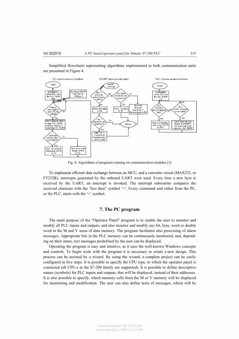
Simplified flowcharts representing algorithms implemented in both communication units are presented in Figure 4.
Fig. 4. Algorithms of programs running on communication modules [3]
To implement efficient data exchange between an MCU, and a converter circuit (MAX232, or FT232R), interrupts generated by the onboard UART were used. Every time a new byte is received by the UART, an interrupt is invoked. The interrupt subroutine compares the received character with the “less then” symbol ‘<’. Every command sent either from the PC, or the PLC, starts with the ‘<’ symbol.
7. The PC program The main purpose of the “Operator Panel” program is to enable the user to monitor and modify all PLC inputs and outputs, and also monitor and modify any bit, byte, word or double word in the M and V areas of data memory. The program facilitates also processing of alarm messages. Appropriate bits in the PLC memory can be continuously monitored, and, depend-ing on their states, text messages predefined by the user can be displayed. Operating the program is easy and intuitive, as it uses the well-known Windows concepts and controls. To begin work with the program it is necessary to create a new design. This process can be assisted by a wizard. By using the wizard, a complete project can be easily configured in five steps. It is possible to specify the CPU type, to which the operator panel is connected (all CPU-s in the S7-200 family are supported). It is possible to define descriptive names (symbols) for PLC inputs and outputs, that will be displayed, instead of their addresses. It is also possible to specify, which memory cells from the M or V memory will be displayed for monitoring and modification. The user can also define texts of messages, which will be
Unauthenticated | 89.73.89.243Download Date | 8/9/13 5:03 PM
K. Mazek, M. Chmiel, J. Kulisz Arch. Elect. Eng. 316
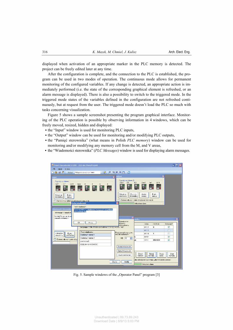
displayed when activation of an appropriate marker in the PLC memory is detected. The project can be freely edited later at any time. After the configuration is complete, and the connection to the PLC is established, the pro-gram can be used in two modes of operation. The continuous mode allows for permanent monitoring of the configured variables. If any change is detected, an appropriate action is im-mediately performed (i.e. the state of the corresponding graphical element is refreshed, or an alarm message is displayed). There is also a possibility to switch to the triggered mode. In the triggered mode states of the variables defined in the configuration are not refreshed conti-nuously, but at request from the user. The triggered mode doesn’t load the PLC so much with tasks concerning visualization. Figure 5 shows a sample screenshot presenting the program graphical interface. Monitor-ing of the PLC operation is possible by observing information in 4 windows, which can be freely moved, resized, hidden and displayed: C the “Input” window is used for monitoring PLC inputs, C the “Output” window can be used for monitoring and/or modifying PLC outputs, C the “Pamięć sterownika” (what means in Polish PLC memory) window can be used for
monitoring and/or modifying any memory cell from the M, and V areas, C the “Wiadomości sterownika” (PLC Messages) window is used for displaying alarm messages.
Fig. 5. Sample windows of the „Operator Panel” program [3]
Unauthenticated | 89.73.89.243Download Date | 8/9/13 5:03 PM

Vol. 62(2013) A PC-based operator panel for Simatic S7-200 PLC 317
As it was already mentioned, a short subprogram, that processes request from the operator panel, has to be continuously executed by the PLC, to enable transmission of required data from the PLC. The appropriate code can be automatically generated by the “Operator Panel” program, and saved to the PC hard disk [3]. The code can then be imported to the PLC con-figuration software (Step 7 MicroWin), and combined with the actual control program.
8. The PLC subprogram As in the Freeport mode no communication protocol is active, data exchange must be handled by the user control program. To initialize and maintain communication with the ope-rator panel presented in the paper, some portions of code need to be added to the user control program. The main purpose of the additional code is to process requests coming from the operator panel, and prepare and send back requested data. The other essential task is to ini-tialize and configure the communication port correctly, after the PLC is restarted. In general the additional code can be divided in three groups: C initialization code, i.e. instructions, that have to be executed once, after the PLC is re-
started, C cyclic code, i.e. instructions, that need to be processed continuously, together with the
main system cycle, C interrupt code, i.e. instructions servicing interrupts triggered by the communication port in
the Freeport mode. All fragments of the code can be automatically generated by the “Operator Panel” program running on a PC, and then imported and combined with the actual control program. The cyclic code was organized into a few subroutines, which are invoked at the end of the main program, after the actual control application is finished. The subroutines check, whether during the last program scan an interrupt from the communication port was triggered, and data containing a command from the operator panel was received. If this happens, a subprogram responsible for servicing the appropriate command, and sending a response to the operator panel is in-voked [9]. The PLC behaves as a passive station, i.e. it never initiates data exchange, but only re-sponds to requests coming from the operator panel, or sends back an acknowledge, that a com-mand was executed correctly. The data received from the operator panel, or sent to it are stored in a buffer. The first byte in the buffer always specifies the number of bytes to be transmitted/received. Successive bytes contain actual data. To implement all the required functionality of the operator panel, a set of commands was designed. Tab. 1 presents a description of some sample commands serviced by the PLC. The commands described in the table are executed in appropriate subroutines. The sub-routines check first, if the format of the command is correct. Listing 1 shows an example code of the subroutine executing the <MWxx?> command.
Unauthenticated | 89.73.89.243Download Date | 8/9/13 5:03 PM

K. Mazek, M. Chmiel, J. Kulisz Arch. Elect. Eng. 318
Table 1. Sample commands serviced by the PLC cyclic code
Command Description <IB0?>, <QB0?>, <IB2?>, etc.
A request for a state of a single input or output byte (IB0, QB0, IB2)
<MBxx?>, <VWxx?>, <MDxx?>, <VDxx?> etc.
A request for the state of a single byte (B), word (W), or double word (D) from the M or V memory. xx is a 2-byte long number of the first byte in the requested area
<Mxx.y?>, <Vxx.y?> A request for the state of a single bit from the M or V memory. xx is a 2-byte long number of the byte, and y is the number of the requested bit.
<QB0@z>, <QB1@z>, <QB2@z>, etc.
Writing a specified value to an output byte. z is the value that is to be written to the byte. After the value is written, the byte is read and sent back to the operator panel.
<MBxx@z>, <VBxx@z>, <MWxx@zz>, <VDxx@zzzz> etc.
Writing a specified value to a byte (B), word (W), or double word (D) from the M or V memory. xx is a 2-byte long byte number, and z, zz, and zzzz correspond respectively to a byte, word, or a double word of data to be written. After the write operation is performed, the state of the affected memory cell is sent back to the operator panel.
<Mxx.y@z>, <Vxx.y@z>
Writing a specified value to a single bit from the M or V memory. xx is the byte number, y – the bit number in the byte, and z is the value to be written (0 or 1). After the write operation is perfor-med, the affected byte is read and sent back to the operator panel.
A sample code of a subroutine servicing a command from the operator panel
//Executing the <MWxx?> command, i. e. a request for the data from //the MWxx word. //The buffer for the received data starts at VB100. //The buffer for the transmitted data starts at VB150. LDB= VB100, 7 // if 7 characters were received AB= VB102, 'M' // and VB102 = ‘M’ AB= VB103, 'W' // and VB103 = ‘W’ AB= VB106, '?' // and VB106 = ‘?’ MOVD &MB0, LD10 // write the pointer to the MB0 byte to LD10 // The address will be used for accessing the
// requested memory word using indirect addressing // MOVW 0, LW4 // write 0 to LW4 MOVW VW104, LW6 // copy the byte number (which is in VW104 // to LW6 +D LD4, LD10 // add LD4 to LD10 MOVD VD100, VD150 // copy the first characters ”<MW” from the // receive buffer to the transmit buffer MOVB 9, VB150 // set the number of characters to be sent to 9 MOVW VW104, VW154 // copy the byte number to the transmit buffer MOVB '=', VB156 // send the ‘=’ character MOVB '>', VB159 // send the ‘>’ character MOVW *LD10, VW157 // send the contents of the word pointed by LD10
Unauthenticated | 89.73.89.243Download Date | 8/9/13 5:03 PM
Vol. 62(2013) A PC-based operator panel for Simatic S7-200 PLC 319
If only direct addressing was used, writing subroutines supporting all possible combina-tions of memory areas, and data lengths (bit, byte, word, or double word) would be a very complex task, and the code would consist of hundreds of lines. Fortunately the S7-200 PLC-s support also indirect addressing. Indirect addressing often enables the programmer to find compact and consistent solutions for tasks processing data tables in memory. The command presented in the example is supposed to read the contents of a word in the M memory, and send it to the operator panel. The MOVD &MB0, LD10 instruction evaluates a pointer to the MB0 address, and stores it in the double word LD10. From that moment, just by incrementing or decrementing the contents of the LD10 variable, we obtain pointers to subsequent bytes in the M memory. Instead of incrementing or decrementing, also integer addition or subtraction can be used. The MOVW *LD10, VW157 instruction reads contents of the word pointed by the pointer stored in LD10, and copies it to VW157, i.e. to the transmit buffer.
9. Conclusions The paper describes a prototype operator panel, which was designed to operate with the S7-200 family of Programmable Logic Controllers from Siemens. Most of the functionality of the operator panel was implemented in a computer program, which runs on a PC. The program communicates with a PLC through its communication port configured in the Freeport mode. A set of commands was designed to facilitate the data exchange. The commands are generated by the operator panel program, and sent to the PLC. The commands are serviced by a set of predefined subroutines, which need to be included in the actual control program. An important part of the design is the interface between the PC, and the Programmable Controller. Two kinds of interface are supported: wired, and wireless. For wired connection a standard PC/PPI cable supplied by Siemens is used. For wireless connection two commu-nication modules were designed, which operate in the free 433 MHz band. The operator panel program is intuitive, and easy to use. States of PLC inputs and outputs are presented using graphical elements. It is possible to modify states of the outputs, and mo-nitor and edit any memory cell from the M and V memory in the PLC. The application sup-ports also alarming. The program can be run on any computer with the MS Windows operating system instal-led. This makes the solution very cost-effective. The whole cost of the components necessary to assemble the communication modules did not exceed €60. Providing both wired and wireless communication radically increases flexibility of the pro-posed solution. The panel can be quickly mounted in areas, where pulling new cables is incon-venient, difficult or expensive. Applying a quarter-wave antenna (c.a. 16.5 cm) allowed to ob-tain reliable communication at distances of up to 30 m (in office space). Immunity to EMC noise in industrial conditions was not tested yet, however wired communication is also avail-able and it can always be considered a backup option, if the wireless communication fails.
Unauthenticated | 89.73.89.243Download Date | 8/9/13 5:03 PM

K. Mazek, M. Chmiel, J. Kulisz Arch. Elect. Eng. 320
References [1] Siemens A.G., Simatic S7-200 Programmable Controller System Manual. 08. 2008. [2] Siemens A.G., S7-200 SIMATIC Text Display (TD) User Manual. 08. 2007. [3] Mazek, K., Panel operatorsko-diagnostyczny współpracujący ze sterownikiem Simatic S7-200.
(Operator and diagnostic panel for Simatic S7-200 controller). Master thesis, Silesian University of Technology, Gliwice (2011) (in Polish).
[4] Doliński J., Mikrokontrolery AVR w praktyce. (AVR Microcontrollers in Practice). BTC, Warszawa (2004) (in Polish).
[5] http://www.propox.com/products/t_202.html, accessed September 2011. [6] Texas Instruments, ‘Chipcon Products: CC1100’, application note. [7] FTDI: ‘FT232RL’, application note. [8] Texas Instruments: ‘MAX232’, application note. [9] Seweryn A., Tworuszka S., Chmiel M., Mocha J., Bezprzewodowy panel operatorski do sterownika
PLC, A Wireless Operator Panel for a PLC, Elektronika 9: 52-55 (2010) (in Polish). [10] Mielczarek W., Szeregowe interfejsy cyfrowe. (Serial digital interfaces). Helion, Gliwice (1994)
(in Polish). [11] Chromik R., RS232 w przykładach na PC i AVR. (RS232 in the examples on the PC and AVR), BTC,
Warszawa (2010) (in Polish).
Unauthenticated | 89.73.89.243Download Date | 8/9/13 5:03 PM