a pdf of the 1988 oscilloscope probes and accessories catalog
TRANSCRIPT

Probe Compensation Range The 1:1 passive probe
Selecting the right probe for yourparticular measurement involves manychoices. This section will give you someideas on how to go about making thebest decision.
When an oscilloscope measurementis made, the circuit under test isdisturbed since energy must betransferred from the circuit to theoscilloscope input. Effectively, thismeans that what is being measured isnot just the circuit under test, but thecombination of the probe, oscilloscopeand the circuit under test. The ideathen, is to select a probe that will affectthe test circuit the least and still havethe necessary characteristics to make themeasurement of choice with accuracy.
Below is a list of probe parametersto be considered when selecting theproper probe for a given measurement:
D AttenuationD Bandwidth (BW)D Pulse responseD Input resistance (Rin)D Input capacitance (Cin)D Form factorD Compensation rangeD Maximum input voltage (Vmax)D Cable lengthD Serviceability
You will note that many probes havea specification that lists the oscilloscopeinput capacitance range over which theycan be used. When choosing a probe,be sure that it can be compensated forthe amount of input capacitance thatyour oscilloscope has.
Most oscilloscopes have 1 megohminput resistance. This input resistanceis in parallel with shunt capacitancethat results from the oscilloscope'sinput components. Probes that haveattenuation factors (other than 1:1)designed for these high-impedanceinputs must have "compensation"networks that adjust the probe'scircuitry to give equal attenuation toall frequencies within their applicationbandwidth. Operating instructionsprovided with the probe explain howto adjust the compensation network toobtain best test signal fidelity.
Types of ProbesThe most common oscilloscope probe
is the "passive probe." It is called thisbecause it has no "active" componentsand has only resistive, capacitive, andinductive circuit elements.
The most frequent trade-offs madein passive probes are betweenattenuation, circuit loading, andbandwidth. For instance, when theattenuation factor is increased, it ispossible to reduce circuit loading andincrease system bandwidth. Forexample, a divide by 10 (10:1) probecan have hundreds of MHz bandwidthwhile a 1:1 (no attenuation) probe islimited to tens of MHz bandwidth.
The 1:1 probe is essentially a lengthof low capacitance coaxial cable witha BNC connector on one end and a probetip on the other. This probe has noattenuation, is shielded, and yields thesame input resistance that the scope has.
The 1:1 probe should be used whensmall signals are being examined andno attenuation can be tolerated. Ithas high input capacitance so it isnormally used only in low-frequencyapplications where limited bandwidthwill not cause measurement errors.
Gain = 1R . = RKO« = 1 Mil
CM = Ci» + Cunt + CKOH
Bandwidth =c.
For: C , = 60pF, R - 1
Input bandwidthot probe: - 2.6 KHz, R» - oo
= 2.6 MHz, R. = 1 K 11- 2.6 MHz, R . = 100 fl
Figure 1. Equivalent circuit of a 1:1 probe
As you might interpret from figure 1,it is usually a poor choice to probe ahigh-frequency high-impedance sourcewith a 1:1 probe since the probe'sbandwidth is low for high-impedancesources.
The 1:1 50Q ProbeThere are two types of 1:1 probes.
Some are designed for high-impedanceoscilloscope inputs, others are designedfor 50O inputs. In general, they differonly in the cable that is used betweenthe tip and scope connector, 50fi 1:1probes use 50O transmission linecoaxial cable and are meant to be usedwith terminated 50O inputs. Highimpedance 1:1 probes use low-capacitance cable specially designed togive best pulse response with highimpedance (usually 1 megohm)oscilloscope inputs.
When a 50O probe is used to probesource impedances close to 50O, thereis little loading of the circuit under test.As the source impedance increases,the SOD probe will increasingly loadthe test circuit, causing errors in thevoltage amplitude measured.
The 10:1 Passive Probe10:1 probes are most frequently
furnished with oscilloscopes whenshipped from the factory. This probeadds attenuation circuitry to its tip anda compensation chassis at its other end.The compensation adjustment allowsfaithful waveform transfer when usedwith different oscilloscopes havingdifferent input capacitance specifications.The 10:1 probe's higher attenuationfactor allows lower input capacitanceand higher bandwidth than the 1:1 probefor the same signal source resistance.
The 10:1 attenuation factor alsoincreases the oscilloscope's viewablemaximum input voltage by a factor of10. Many oscilloscopes have maximuminput settings of 5 volts per division,so this probe allows viewing severalhundred volts up to the maximum limitof the probe itself.
c=© k,TE5TT T7r~ IWhen correctly compensated
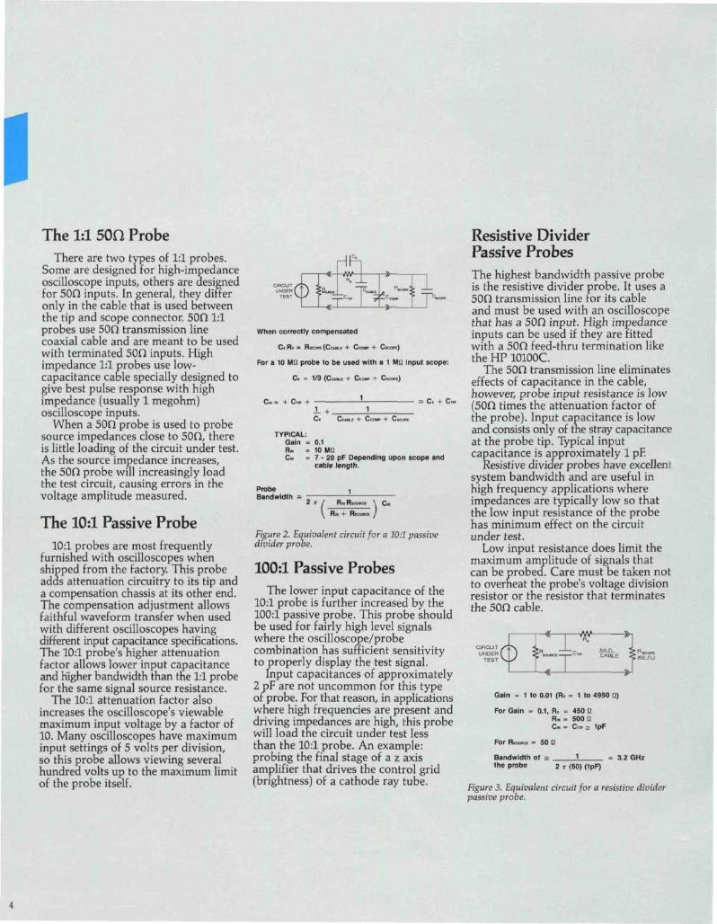
C,R< = R,™<C«.u + C™. + C«<«)
For a 10 Ml: probe to be used with a 1 Mtt input scope:
C. -- 1/9 (C •... • + C - + C )
c« = + c.- + 1
C" CUKE + Ccour + CKOH
TYPICAL:Gain = 0.1R* = 10 MSIC.H = 7 - 20 pF Depending upon scope and
cable length.
ProbeBandwidth =
Figure 2. Equivalent circuit for a 10:1 passivedivider probe.
100:1 Passive ProbesThe lower input capacitance of the
10:1 probe is further increased by the100:1 passive probe. This probe shouldbe used for fairly high level signalswhere the oscilloscope/probecombination has sufficient sensitivityto properly display the test signal.
Input capacitances of approximately2 pF are not uncommon for this typeof probe. For that reason, in applicationswhere high frequencies are present anddriving impedances are high, this probewill load the circuit under test lessthan the 10:1 probe. An example:probing the final stage of a z axisamplifier that drives the control grid(brightness) of a cathode ray tube.
Resistive DividerPassive ProbesThe highest bandwidth passive probeis the resistive divider probe. It uses a50Q transmission line for its cableand must be used with an oscilloscopethat has a SOU input. High impedanceinputs can be used if they are fittedwith a 500 feed-thru termination liketheHPlOlOOC.
The SDH transmission line eliminateseffects of capacitance in the cable,however, probe input resistance is low(500 times the attenuation factor ofthe probe). Input capacitance is lowand consists only of the stray capacitanceat the probe tip. Typical inputcapacitance is approximately 1 pF.
Resistive divider probes have excellentsystem bandwidth and are useful inhigh frequency applications whereimpedances are typically low so thatthe low input resistance of the probehas minimum effect on the circuitunder test.
Low input resistance does limit themaximum amplitude of signals thatcan be probed. Care must be taken notto overheat the probe's voltage divisionresistor or the resistor that terminatesthe 50n cable.
Gain = 1 to 0.01 (R. = 1 to 4950 fi)
For Gain = 0.1, R. = 450 12R -, = 500 1!C« m C™ - 1pF
= 50 U
Bandwidth of = 1the probe 2 * (50) (1pF)
3.2 GHz
Figure 3. Equivalent circuit for a resistive dividerpassive probe.
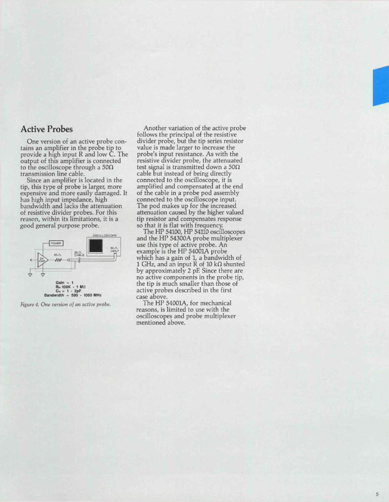
Active ProbesOne version of an active probe con-
tains an amplifier in the probe tip toprovide a high input R and low C. Theoutput of this amplifier is connectedto the oscilloscope through a 50Otransmission line cable.
Since an amplifier is located in thetip, this type of probe is larger, moreexpensive and more easily damaged. Ithas high input impedance, highbandwidth and lacks the attenuationof resistive divider probes. For thisreason, within its limitations, it is agood general purpose probe.
OSCILLOSCOPE
Gain = 1H , 100K - 1 M:;C« = 1 - 2pF
Bandwidth = 500 - 1000 MHz
Figure 4. One version of an active probe.
Another variation of the active probefollows the principal of the resistivedivider probe, but the tip series resistorvalue is made larger to increase theprobe's input resistance. As with theresistive divider probe, the attenuatedtest signal is transmitted down a 50Qcable but instead of being directlyconnected to the oscilloscope, it isamplified and compensated at the endof the cable in a probe pod assemblyconnected to the oscilloscope input.The pod makes up for the increasedattenuation caused by the higher valuedtip resistor and compensates responseso that it is flat with frequency.
The HP 54100, HP 54110 oscilloscopesand the HP 54300A probe multiplexeruse this type of active probe. Anexample is the HP 54001A probewhich has a gain of 1, a bandwidth of1 GHz, and an input R of 10 kn shuntedby approximately 2 pF. Since there areno active components in the probe tip,the tip is much smaller than those ofactive probes described in the firstcase above.
The HP 54001A, for mechanicalreasons, is limited to use with theoscilloscopes and probe multiplexermentioned above.
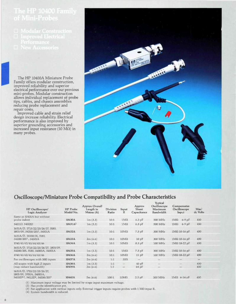
The HP 10400A Miniature ProbeFamily offers modular construction,improved reliability and superiorelectrical performance over our previousmini-probes. Modular constructionallows individual replacement of probetips, cables, and chassis assembliesreducing probe replacement andrepair costs.
Improved cable and strain reliefdesign increase reliability. Electricalperformance is also improved bysuperior grounding accessories andincreased input resistance (10 MO) inmany probes.
Oscilloscope/Miniature Probe Compatibility and Probe Characteristics
HP Oscilloscope/ HP ProbeLogic Analyzer Model No.
Same as 10431A but withoutprobe indent 10430A
541UD, 54112D 10431A2
1631A/D, 1715/22/25/26/27, 5185,1805/09, 54200/2013, 54501A 10432A
163LA/D, 16530/31, 5185,54200/2013 , 54501A
1740/41/42/43/44/45/46
1631A/D, 1715/22/25/26/27, 1805/09,54200/201, 5185, 54003A, 54501A
1740/41/42/43/44/45/46
For oscilloscopes with 50O inputs
All scopes with high Z inputs(may reduce bandwidth)
1631A/D, 1715/22/25/26/27,1805/09, 1950A, 54003A,541HD3-4, 54U2D3, 54200/2013 10440A
Approx OverallLength in
Metres ( f t )
1m (3.3)
1m (3.3)
1m (3.3)
2m (6.6)
DivisionRatio
10:1
10; 1
10:1
100:1
InputR
iMfl
IMfl
10433A
10434A
10435 A10436A
10437 A
10438A10439A
2m (6.6)
1m (3.3)
1m (3.3)
2m (6.6)2m (6.6)
1m (3.3)2m (6.6)
10:1
10:1
10:110:1
1:1
1:1
1:1
lOMn
ioMn
iMnioMn
son
:
ioMn
ApproxShunt
Capacitance
6.5pF
6.5 pF
7.5 pF
40 pF64 pF
2.5 pF
TypicalOscilloscope
MaximumBandwidth
500MHz
500MHz
CompensatesOscilloscope Max1
Input dc Volts
IMO 6-9 pF
IMfl 6-9 pF
300 MHz IMfl 10-16 pF
300 MHz IMfl 6-14 pF
(1) Maximum input voltage may be limited by scope input maximum voltage.(2) Has probe identification pin.(3) For application with vertical inputs only. External trigger inputs require probes with 1 Mfl input R.(4) System bandwidth is reduced.
450
450
450
10 pF
8.5 pF
7.5pF
11 pF
300 MHz
100 MHz
300 MHz
100 MHz
IMn 10-16 pF
iMfl 18-22 pF
iMn 10-16 pF
1MO 18-22 pF
450
450
450
450
450450
450
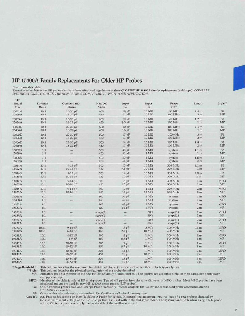
HP 10400A Family Replacements For Older HP ProbesHow to use this table.The table below lists older HP probes that have been obsoleted together with their CLOSEST HP 10400A family replacement (bold type). COMPARESPECIFICATIONS TO CHECK THE NEW PROBE'S COMPATIBILITY WITH YOUR APPLICATION.
HPModel
No.
10001 A10436A
10003A10434 A
10004D10434A
10005D10436A
10006 D10436A
10007B10438A
.0008B10439A
1001 4 A10432A
10016B10433A
10017A10435A
10018A10433 A
10021 A10438A
10022A10439A
10026A10437A
10027A10437 A
10032A10440A
10033 A10431A
10040A10434A
10041A10436A
10042A10436A
*Usage Bandwidth**Sty!e
MP
MPO
SI:
52:
Note (1):
Division Compensation Max DC Input Input Usage LengthRatio Range Volts C R BW*
10:1 15-55 pF 600 10 pF 10 Mfl 30 MHz 1.5m10:1 18-22 pF 450 11 pF 10 Mfl 100 MHz 2 m10:1 15-55 pF 600 10 pF 10 Mfl 45 MHz 1.2 m10:1 18-22 pF 450 8.5 pF 10 Mfl 100 MHz 1 m10:1 20-30 pF 500 10 pF 10 MO 100 MHz l.lm10:1 18-22 pF 450 8.5 pF 10 MO 100 MHz 1 m10:1 20-30 pF 500 17 pF 10 Mfl 100MHz 3 m10:1 18-22 pF 450 11 pF 10 Mfl 100 MHz 2 m10:1 20-30 pF 500 14 pF 10 MO 100 MHz 1.8 m10:1 18-22 pF 450 11 pF 10 MO 100 MHz 2m1:1 500 40 pF 1 Mfl system 1.1 m1:1 450 40 pF 1 Mfl system 1 m
1:1 500 60 pF 1 Mfl system 1.8m1:1 450 64 pF 1 MO system 2 m
10:1 9-13 pF 500 10 pF 10 Mfl 300 MHz 1.1 m10:1 10-16 pF 450 7.5 pF 10 MO 300 MHz 1 m10:1 9-13 pF 500 14 pF 10 Mfl 300 MHz 1.8m10:1 10-16 pF 450 10 pF 10 MO 300 MHz 2 m10:1 9-14 pF 300 8 pF 1 Mfl 300 MHz 1 m10:1 10-16 pF 450 7.5 pF 1 Mfl 300 MHz 1 m10:1 9-14 pF 300 10 pF 1 Mfl 300 MHz 2 m10:1 10-16 pF 450 10 pF 10 Mfl 300 MHz 2 m1:1 300 36 pF 1 Mfl system 1 m1:1 450 40 pF 1 Mfl system 1 m
1:1 300 62 pF 1 Mfl system 2 m1:1 450 64 pF 1 Mfl system 2 m
1:1 scope(l) 50fl scope(l) 1 m1:1 scope(l) 50n scope(l) 2m
1:1 scope(l) 50fl scope(l) 2 m1:1 scope(l) 500 scope(l) 2 m
100:1 9-14 pF 300 3 pF 3 Mfl 300 MHz 1.1 m100:1 6-14 pF 450 2.5 pF 10 MO 300 MHz 2 m10.-1 4-12 pF 200 8pF 1 Mfl 500MHz 1m10:1 6-9 pF 450 6,5 pF 1 Mfl 500 MHz 1 m10:1 20-30 pF 300 9 pF 1 Mfl 100 MHz 1 m10:1 18-22 pF 450 8,5 pF 10 Mfl 100 MHz 1 m10:1 20-26 pF 300 12 pF 1 Mfl 100 MHz 2 m10:1 18-22 pF 450 11 pF 10 Mfl 100 MHz 2m10:1 20-24 pF 300 15 pF 1 Mfl 100 MHz 3 m10:1 18-22 pF 450 11 pF 10 Mfl 100 MHz 2 m
Style*
SIMPSIMPS2
MPS2MPS2
MPS2
MPS2
MPS2
MPS2
MPMPOMP
MPOMP
MPOMP
MPOMP
MPOMP
MPOMP
MPOMP
MPOMP
MPOMP
MPOMP
MPOMP
: This column describes the max imum bandwidth of the oscilloscope with which this probe is typically used.; This column describes the physical configuration of the probe described:: Miniature probe, a member of the new HP 10400 family of mini-probes. These probes replace other styles in most cases. See photograph
on opposite page,i Member of the older family of HP mini-probes. Tips of MP probes have the same diameter as MPO probes. Most MPO probes have been
obsoleted and are replaced by new HP 10400A series probes (MP probes).: Older standard probes. See Oscilloscope Probe Accessory Tree for adapters that allow use of standard probe accessories on new
HP 10400 series probes.Older probes also referred to as standard. See Oscilloscope Probe Accessory tree.
: 50fl Probes: See section on How To Select A Probe for details. In general, the maximum input voltage of a 50fl probe is dictated bythe maximum input voltage of the oscilloscope that it is used with in the 50fl input mode. The system bandwidth when using a 50O probewith a 50fl test source is generally the bandwidth of the oscilloscope used.
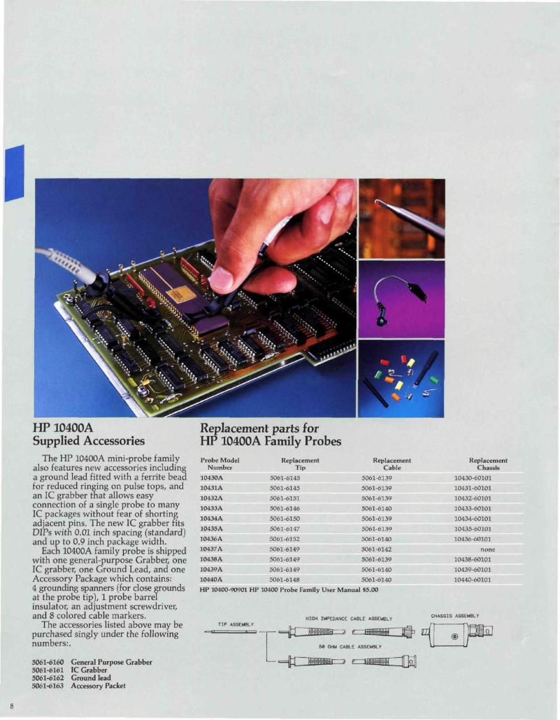
HP 10400ASupplied Accessories
The HP 10400A mini-probe familyalso features new accessories includinga ground lead fitted with a ferrite beadfor reduced ringing on pulse tops, andan 1C grabber that allows easyconnection of a single probe to many1C packages without fear of shortingadjacent pins. The new 1C grabber fitsDIPs with 0.01 inch spacing (standard)and up to 0.9 inch package width.
Each 10400A family probe is shippedwith one general-purpose Grabber, one1C grabber, one Ground Lead, and oneAccessory Package which contains:4 grounding spanners (for close groundsat the probe tip), 1 probe barrelinsulator, an adjustment screwdriver,and 8 colored cable markers.
The accessories listed above may bepurchased singly under the followingnumbers:.
5061-6160 General Purpose Grabber5061-6161 1C Grabber5061-6162 Ground lead5061-6163 Accessory Packet
Replacement parts forHP 10400A Family ProbesProbe Model
Number
10430A
10431 A
10432A
10433A
10434 A
10435A
10436A
10437 A
10438A
10439A
10440A
ReplacementTip
5061-6145
5061-6145
5061-6151
5061-6146
5061-6150
5061-6147
5061-6152
5061-6149
5061-6149
5061-6149
5061-6148
HP 10400-90901 HP 10400 Probe Family
ReplacementCable
5061-6139
5061-6139
5061-6139
5061-6140
5061-6139
5061-6139
5061-6140
5061-6142
5061-6139
5061-6140
5061-6140
ReplacementChassis
10430-60101
10431-60101
10432-60101
10433-60101
10434-60101
10435-60101
10436-60101
none10438-60101
10439-60101
10440-60101
HIGH IMPEDANCE CABLE ASSEMBLYCHASSIS ASSEMBLY
TIP ASSEMBLY
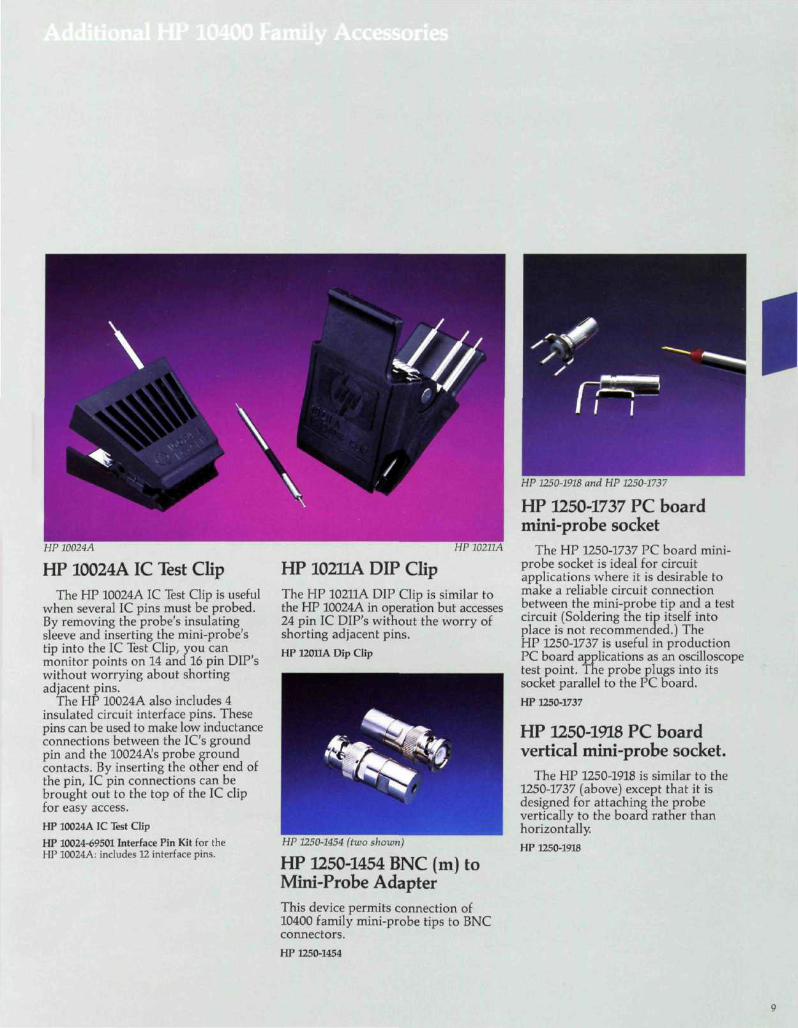
HP 10024A
HP 10024A 1C Test ClipThe HP 10024A 1C Test Clip is useful
when several 1C pins must be probed.By removing the probe's insulatingsleeve and inserting the mini-probe'stip into the 1C Test Clip, you canmonitor points on 14 and 16 pin DIP'swithout worrying about shortingadjacent pins.
The HP 10024A also includes 4insulated circuit interface pins. Thesepins can be used to make low inductanceconnections between the IC's groundpin and the 10024A's probe groundcontacts. By inserting the other end ofthe pin, 1C pin connections can bebrought out to the top of the 1C clipfor easy access.HP 10024A 1C Test Clip
HP 10024-69501 Interface Pin Kit for theHP 10024A: includes 12 interface pins.
HP 10211A
HP 10211A DIP ClipThe HP 10211A DIP Clip is similar tothe HP 10024A in operation but accesses24 pin 1C DIP's without the worry ofshorting adjacent pins.HP 12011A Dip Clip
HP 1250-1454 (two shown)
HP 1250-1454 BNC (m) toMini-Probe AdapterThis device permits connection of10400 family mini-probe tips to BNCconnectors.HP 1250-1454
HP 1250-1918 and HP 1250-1737
HP 1250-1737 PC boardmini-probe socket
The HP 1250-1737 PC board mini-probe socket is ideal for circuitapplications where it is desirable tomake a reliable circuit connectionbetween the mini-probe tip and a testcircuit (Soldering the tip itself intoplace is not recommended.) TheHP 1250-1737 is useful in productionPC board applications as an oscilloscopetest point. The probe plugs into itssocket parallel to the PC board.HP 1250-1737
HP 1250-1918 PC boardvertical mini-probe socket.
The HP 1250-1918 is similar to the1250-1737 (above) except that it isdesigned for attaching the probevertically to the board rather thanhorizontally.
HP 1250-1918
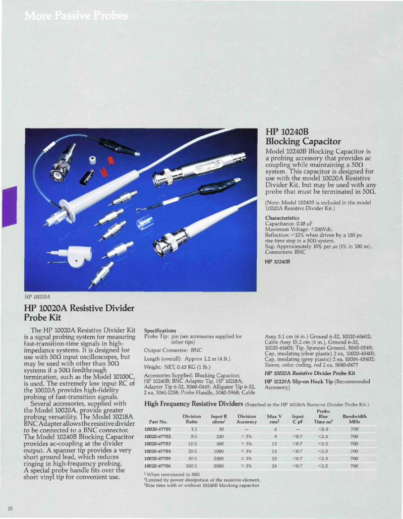
HP 10020A
HP 10020A Resistive DividerProbe Kit
The HP 10020A Resistive Divider Kitis a signal probing system for measuringfast-transition-time signals in high-impedance systems. It is designed foruse with 50O input oscilloscopes, butmay be used with other than 50Osystems if a 50O feedthroughtermination, such as the Model 10100C,is used. The extremely low input RC ofthe 10020A provides high-fidelityprobing of fast-transition signals.
Several accessories, supplied withthe Model 10020A, provide greaterprobing versatility. The Model 10218ABNC Adapter allows the resistive dividerto be connected to a BNC connector.The Model 10240B Blocking Capacitorprovides ac-coupling at the divideroutput. A spanner tip provides a veryshort ground lead, which reducesringing in high-frequency probing.A special probe handle fits over theshort vinyl tip for convenient use.
SpecificationsProbe Tip: pin (see accessories supplied for
other tips)
Output Connector: BNC
Length (overall): Approx 1.2 m (4 ft.)
Weight: NET, 0.45 KG (1 Ib.)
Accessories Supplied: Blocking Capacitor,HP 10240B; BNC Adapter Tip, HP 10218A;Adapter Tip 6-32, 5060-0449; Alligator Tip 6-32,2 ea, 5061-1258; Probe Handle, 5040-5968; Cable
HP 10240BBlocking CapacitorModel 10240B Blocking Capacitor isa probing accessory that provides accoupling while maintaining a 50fisystem. This capacitor is designed foruse with the model 10020A ResistiveDivider Kit, but may be used with anyprobe that must be terminated in 50O,
(Note: Model 10240B is included in the model10020A Resistive Divider Kit.)
CharacteristicsCapacitance: 0.18 fiFMaximum Voltage: ±200Vdc.Reflection: <12% when driven by a 150 psrise time step in a 50fi system.Sag: Approximately 10% per /js (1% in 100 ns).Connectors: BNC
HP 10240B
Assy. 5.1 cm (6 in.) Ground 6-32, 10020-61602;Cable Assy 15.2 cm (6 in.). Ground 6-32,10020-61603; Tip, Spanner Ground, 5060-0549;Cap, insulating (clear plastic) 2 ea, 10020-45401;Cap, insulating (grey plastic) 2 ea, 10004-45402;Sleeve, color coding, red 2 ea, 5040-0477
HP 10020A Resistive Divider Probe Kit
HP 10229A Slip-on Hook Tip (RecommendedAccessory)
High Frequency Resistive Dividers (Supplied in the HP IOOZOA Resistive Divider Probe Kit.)
Part No.10020-6770110020-6770210020-6770310020-6770410020-6770510020-67706
DivisionRatio
1:1
5:1
10:1
20:1
50:1
100:1
Input Rohms1
50
250
500
1000
25005000
DivisionAccuracy
-
±3%
±3%
±3%
±3%
±3%
Max Vrms2
6
9
12
15
25
35
InputCpF
-<0.7
<0.7<0.7<0.7<0.7
ProbeRise
Time ns3
<0.5<0.5<0.5<0.5<0.5<0.5
BandwidthMHz700
700
700
700
700
7001 When terminated in 50f!2Limited by power dissipation of the resistive element.3Rise time with or without 10240B blocking capacitor
10
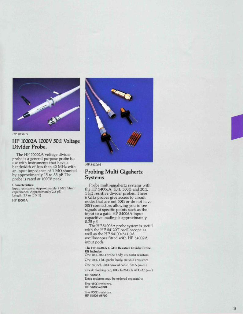
HP 10002A
HP 10002A1000V 50:1 VoltageDivider Probe.
The HP 10002A voltage dividerprobe is a general purpose probe foruse with instruments that have abandwidth of less than 40 MHz withan input impedance of 1 Mfi shuntedby approximately 15 to 55 pF. Theprobe is rated at 1000V peak.
Characteristics:Input resistance: Approximately 9 Mft. Shuntcapacitance: Approximately 2.5 pF.Length: 1.7 m (5.5 ft)
HP 10002A
HP 54006A
Probing Multi GigahertzSystems
Probe multi-gigahertz systems withthe HP 54006A, 10:1, 500O and 20:1,1 kO resistive divider probes. These6 GHz probes give access to circuitnodes that are not 50fl or do not have50O connectors allowing you to seesignals at specific points such as theinput to a gate. HP 54006A inputcapacitive loading is approximately0.25 pF.
The HP 54006A probe system is usefulwith the HP 54120T oscilloscope aswell as the HP 54100/54110Aoscilloscopes fitted with HP 54002Ainput pods.The HP 54006A 6 GHz Resistive Divider ProbeKit includes:One 10:1, 5000 probe body, six 450fl resistors.
One 20:1, 1 kfl probe body, six 950ft resistors
One 36 inch, 50ft coaxial cable, SMA (m-m)
One dc blocking cap, 10 GHz-26 GHz APC-3.5 (m-f)
HP 54006AExtra resistors may be ordered separately:
Five 450ft resistors.HP 54006-68701
Five 950O resistors.HP 54006-68702
11
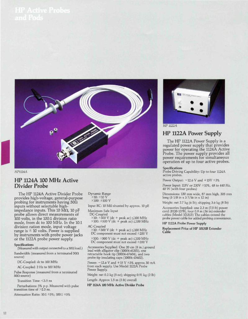
HP1124A
HP 1124A 100 MHz ActiveDivider Probe
The HP 1124A Active Divider Probeprovides high-voltage, general-purposeprobing for instruments having 50Oinputs without selectable high-impedance inputs. This 10 MO, 10 pFprobe allows direct measurements of100 volts, in the 100:1 division ratiomode, from dc to 100 MHz. In the 10:1division ration mode, input voltagerange is ± 10 volts. Power is suppliedby instruments with probe power jacksor the 1122A probe power supply.Specifications
(Measured with output connected to a 50CI load.)
Bandwidth: (measured from a terminated 50fisource)
DC-Coupled: dc to 100 MHz
AC-Coupled: 2 Hz to 100 MHz
Pulse Response (measured from a terminated50O source)
Transition Time: <3.5 ns
Perturbations: 5% p-p. Measured with pulsetransition time of >2.5 ns.
Attenuation Ratio: 10:1 ±5%; 100:1 ±5%
Dynamic RangeX10: ±10 VX100: ±100 V
Input RC: 10 Mfi shunted by approx. 10 pF.
Maximum Safe InputDC-Coupled
X10: ±300 V (dc + peak ac) <100 MHzX100: ±500 V (dc + peak ac) <100 MHz
AC-CoupledX10: ±300 V (dc + peak ac) <100 MHzDC component must not exceed ±200 V
XlOO: ±500 V (dc + peak ac) <100 MHzDC component must not exceed ±200 V
Accessories Supplied: One 20 cm (8 in.) groundlead with alligator clip (10004-61301), oneretractable hook tip (10004-67604), and twoprobe tip insulating caps (10004-45402).
Power: -12.6 V and +15 V ±3% approx 30 mAfrom each supply. Use Model 1122A ProbePower Supply.
Weight: net 0.2 kg (5 oz); shipping 0.91 kg (2 Ib)
Length: Approx 1.5 m (5 ft) overall
HP 1124A 100 MHz Active Divider Probe
HP 32224
HP U22A Power SupplyThe HP 1122A Power Supply is a
regulated power supply that providespower for operating the 1124A ActiveProbe. The power supply provides allpower requirements for simultaneousoperation of up to four active probes.
SpecificationsProbe Driving Capability: Up to four 1124Aactive probes.
Power Output: -12.6 V and +15V ±3%
Power Input: 115V or 230V ±10%, 48 to 440 Hz,40 W (with four probes)
Dimensions: 130 mm wide, 87 mm high, 305 mmlong (5 1/8 in x 3 7/16 in x 12 in)
Weight: net 2.7 kg (6 Ib); shipping 3.6 kg (8 Ib)
Accessories Supplied: one 2.3 m (7.5 ft) powercord (8120-1378), four 0.9 m (36 in) extendercables (Model 10131B) The cables extend theprobe power cable for added probing convenience.
HP 1122A Probe Power Supply
Replacement Price of HP 10131B ExtenderCable
12
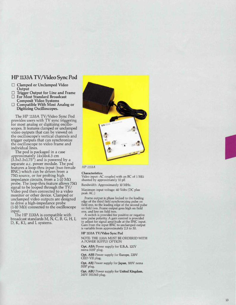
HP 1I33A TV/Video Sync PodD Clamped or Undamped Video
OutputD Trigger Output for Line and FrameD For Most Standard Broadcast
Composit Video SystemsD Compatible With Most Analog or
Digitizing Oscilloscopes.
The HP 1133A TV/Video Sync Podprovides users with TV sync triggeringfor most analog or digitizing oscillo-scopes. It features clamped or undampedvideo outputs that can be viewed onthe oscilloscope's vertical channels andtrigger outputs that can synchronizethe oscilloscope to video Frame andindividual lines.
The pod is packaged in a caseapproximately 14x14x4.5 cm(5.5x5.5x1.75') and is powered by aseparate a.c. power module. The podfeatures a loop-thru input (two femaleBNC) which can be driven from a75O source, or for probing highimpedance circuits, from a 1-10 MOprobe. The loop-thru feature allows 75Qsignal to be looped through the TV/Video pod then connected to a videomonitor or other device. Clamped orundamped video outputs are designedto drive a high-im peel a nee probe(1-10 MO) connected to the oscilloscopeinput.
The HP 1133A is compatible withbroadcast standards M, N, C, B, G, H, I,D, K, Kl, and L systems.
HP 1133 A
Characteristics:Video input: AC coupled with an RC of 1 MOshunted by approximately 10 pE
Bandwidth: Approximately 10 MHz.
Maximum input voltage: 40 Volts (DC pluspeak AC.)
Frame output is phase locked to the leadingedge of the third field synchronizing pulse onfield one, to the leading edge of the second pulseon field two. Frame output goes high on fieldone, and low on field two.
A switch is provided for positive or negativesync pulse polarity. A gain control is providedto adjust for signal amplitude at the BNC input.Gain from the input BNC to undamped outputis variable from approximately 2.5 to 50.
HP 1133A TV/Video Sync Pod
NOTE: THE 1133A MUST BE ORDERED WITHA POWER SUPPLY OPTION
Opt. ABA Power supply for U.S.A, 120Vnema 515P plug.
Opt. ABB Power supply for Europe, 220VCEE7-VII plug.
Opt. ABJ Power supply for Japan, 100V nema515P plug.
Opt. ABU Power supply for United Kingdom,240V BS1363 plug.
13
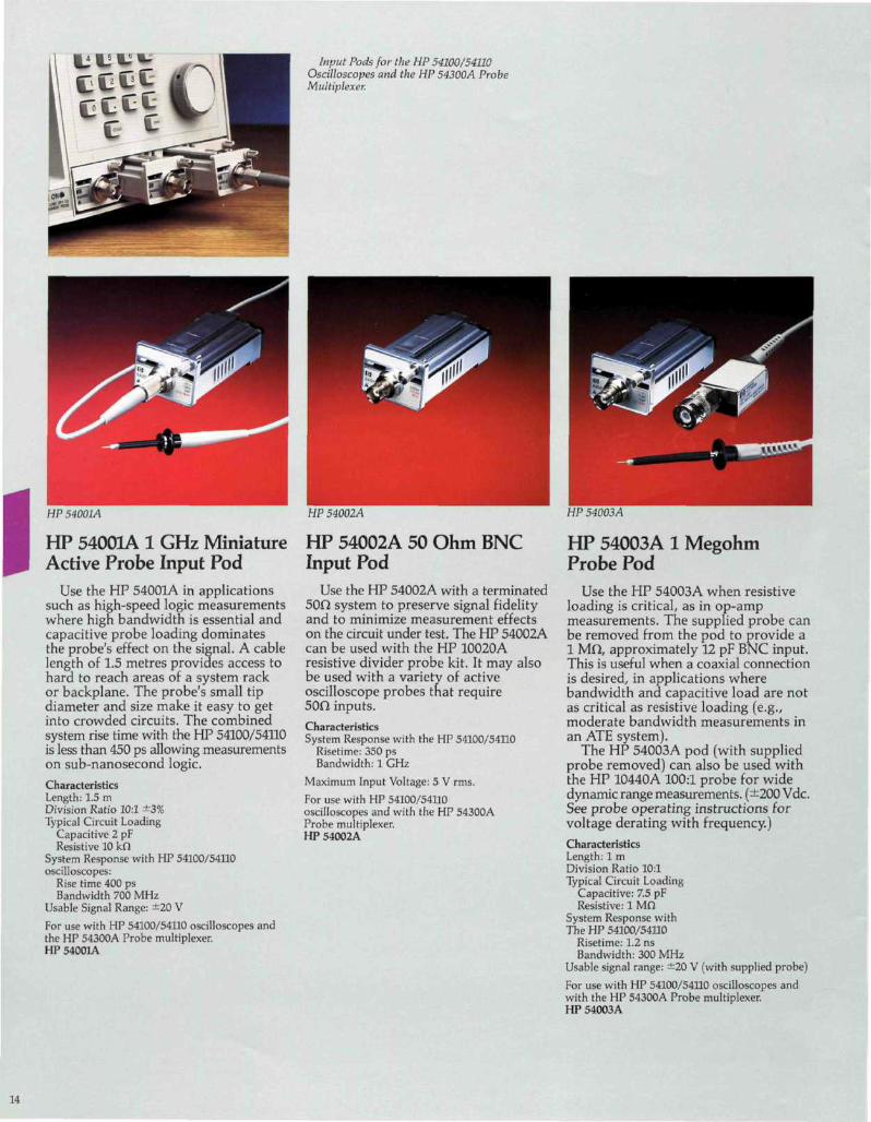
Input Pods for the HP 54100/54TLOOscilloscopes and the HP 54300A ProbeMultiplexer.
HP 54001A
HP 54001A 1 GHz MiniatureActive Probe Input Pod
Use the HP 54001A in applicationssuch as high-speed logic measurementswhere high bandwidth is essential andcapacitive probe loading dominatesthe probe's effect on the signal. A cablelength of 1.5 metres provides access tohard to reach areas of a system rackor backplane. The probe's small tipdiameter and size make it easy to getinto crowded circuits. The combinedsystem rise time with the HP 54100/54110is less than 450 ps allowing measurementson sub-nanosecond logic.
CharacteristicsLength: 1.5 mDivision Ratio 10:1 ±3%Typical Circuit Loading
Capacitive 2 pFResistive 10 kO
System Response with HP 54100/54110oscilloscopes:
Rise time 400 psBandwidth 700 MHz
Usable Signal Range: ±20 V
For use with HP 54100/54110 oscilloscopes andthe HP 54300A Probe multiplexer.HP 54001A
HP 54002A
HP 54002A 50 Ohm BNCInput Pod
Use the HP 54002A with a terminated50O system to preserve signal fidelityand to minimize measurement effectson the circuit under test. The HP 54002Acan be used with the HP 10020Aresistive divider probe kit. It may alsobe used with a variety of activeoscilloscope probes that require50n inputs.CharacteristicsSystem Response with the HP 54100/54110
Risetime: 350 psBandwidth: 1 GHz
Maximum Input Voltage: 5 V rms.
For use with HP 54100/54110oscilloscopes and with the HP 54300AProbe multiplexer.HP 54002A
HP 54003 A
HP 54003A 1 MegohmProbe Pod
Use the HP 54003A when resistiveloading is critical, as in op-ampmeasurements. The supplied probe canbe removed from the pod to provide a1 Mn, approximately 12 pF BNC input.This is useful when a coaxial connectionis desired, in applications wherebandwidth and capacitive load are notas critical as resistive loading (e.g.,moderate bandwidth measurements inan ATE system).
The HP 54003A pod (with suppliedprobe removed) can also be used withthe HP 10440A 100:1 probe for widedynamic range measurements. (±200 Vdc.See probe operating instructions forvoltage derating with frequency.)CharacteristicsLength: 1 mDivision Ratio 10:1Typical Circuit Loading
Capacitive: 7.5 pFResistive: 1 Mn
System Response withThe HP 54100/54110
Risetime: 1.2 nsBandwidth: 300 MHz
Usable signal range: ±20 V (with supplied probe)
For use with HP 54100/54110 oscilloscopes andwith the HP 54300A Probe multiplexer.HP 54003A
14