a performance study of beam column connections of self-centering steel...
TRANSCRIPT

Advanced Steel Construction Vol. 12, No. 4, pp. 446-465 (2016) 446
A PERFORMANCE STUDY OF BEAM COLUMN CONNECTIONS OF SELF-CENTERING STEEL FRAME WITH
U-SHAPED STEEL DAMPERS
Yanxia Zhang1, 2, *, Zhenxing Li 2,Wenzhan Zhao 2, Rui Li 2 and Jiarui Li 2
1 Associate Professor, Beijing Higher Institution Engineering Research Center of Structural Engineering and New Materials, Beijing University of Civil Engineering and Architecture, Beijing 100044, China
2 Postgraduate, School of Civil and Transportation Engineering, Beijing University of Civil Engineering and Architecture, Beijing 100044, China
*(Corresponding author: E-mail: [email protected])
Received: 2 November 2015; Revised: 26 November 2015; Accepted: 2 December 2016 ABSTRACT: This study proposes a new type of self-centering beam-column connection with U-shaped steel dampers. A simplified hysteresis model of the connection was derived firstly. Then the preliminary design of self-centering beam-column connection with U-shaped steel dampers was proposed. A pseudo-static test and numerically simulation was conducted. The test results showed that the proposed self-centering connection could provide reliable energy-dissipation and self-centering capacities. The capacity that the hysteresis model could predict the moment-rotation behavior of the U-shaped steel damper and the connection was proved by the comparison of the experiments and the theories. The simulation results are consistent with the test results and simplified hysteresis model. The effects of the width and the height of the U-shaped steel damper and the thickness of the steel plate of the U-shaped steel damper on the performance of the connection were also analyzed by the numerically simulation. The results showed that the height of the U-shaped steel damper had a relatively small impact on the connection; a change in the thickness of the U-shaped steel damper mainly affects the load-bearing capacity and stiffness of the connection but does not affect the energy-dissipation capacity of the connection significantly. The width of the U-shaped steel damper has the greatest impact on the connection. The load-bearing capacity, the post-opening stiffness and the energy-dissipation capacity of the connection would all increased with increasing width of the U-shaped steel damper. Keywords: Self-centering steel frame, beam-column connection, U-shaped steel damper, energy dissipation DOI:10.18057/IJASC.2016.12.4.5
1. INTRODUCTION Self-centering steel moment-resisting frames (SC-MRF) have received wide attention since they were proposed. The beams and columns of an SC-MRF are connected differently from that of a conventional frame with rigid connections. In a SC-MRF, the beams and columns are pressed tightly against each other by the pretension of pre-stressed steel strands, gap openings are generated at the beam-column connections and energy dissipated elements, such as angle steel, develop plastic deformation to dissipate energy during an earthquake .Thus, the main structure will sustain little or no damage and can recover to the initial position after the earthquake. Since. Garlock et al.[1] from Princeton University completed the first test of the beam-column connections of a SC-MRF s in 1997, Ricles et al.[2], Garlock et al.[3] and Christopoulos et al.[4] have studied SC connections that dissipate energy through top-seat angle steel and energy-dissipation rods, and Cruz[5] proposed a SC beam-column connection that dissipates energy through friction , Iyama et al. [6] used two types of friction devices: a PT friction damped connection placed on the top and the bottom of the beam flanges, and a bottom flange-only friction device. In the same year, Wolski et al. [7] designed beam bottom flange friction devices (BFFD) and avoided interference with the floor slab. Lin et al. [8] used web friction devices (WFDs) on beams for energy dissipation in the SC-MRF. This study proposes a beam-column connection with U-shaped steel damper connection (SCCUD) for SC-MRF. A test and a numerical simulation of the proposed connection are conducted under low-cycle repeated loading conditions, and nine connection finite element model of the SCCUD is developed for the analysis of variable parameters.

447 Yanxia Zhang, Zhengxing Li, Wenzhan Zhao, Rui Li and Jiarui Li
2. CONNECTION DETAILS AND THE THEORETICAL HYSTERESIS MODEL
2.1 Connection details The main elements of SCCUD connection include a beam, a column, pre-stressed steel strands and U-shaped steel dampers (Figure 1). Steel supports are placed symmetrically on the two sides of the beam web and are welded to the column flanges during the manufacturing process in the factory. A U-shaped steel damper is welded onto both the top and bottom surfaces of each steel support. Figure 2 shows the main assembly process. First, the bolts that connect the U-shaped steel dampers with the beam flanges are initially screwed. Steel strands are then passed through the pre-drilled holes. Pressure sensors are installed at the anchor ends to measure the tension of each strand (Figure 2(a)). The steel strands are tensioned, and the tension of each strand is accurately adjusted (Figure 2(b), (c)). Finally, the bolts that connect the U-shaped steel dampers to the beam flanges are screwed, which completes the assembly process. Figure 2(d) shows a photograph of the connection after assembly is completed. The beam is pressed tightly against the surface of the column by the pretension of the steel strands and bears the shear forces at the beam ends through the friction on the contact surfaces. Under seismic loading, an opening is generated at the contact between the beam and the column. The U-shaped steel dampers begin to deform plastically as the opening increases and thus dissipate the energy to reduce or even prevent damage to the main beam-column structure. After the seismic event, the structure recovers to its original position under the pretension of the pre-stressed steel strands.
Figure 1. The Details
(a)Installing the pressure sensor (b)Pretensioning the strands

A Performance Study of Beam Column Connections of Self-Centering Steel Frame with U-Shaped Steel Dampers 448
(c)Adjust posttension force (d)Assembly is completed
Figure 2. The Assembly Process of the SCCUD Connection 2.2 Hysteresis Model The rotational stiffness of the SCCUD connection is provided by the pre-stressed steel strands and the U-shaped steel dampers. When an opening is generated in the beam-column structure, the moment that is needed for the deformation and yielding of the U-shaped steel dampers can be calculated using the equation MU=KUθr, where KU represents the rotational stiffness of each U-shaped damper, and θr represents the rotation angle of the opening between the beam and the column. The value of KU can be considered to have two parts based on the bilinear hardening model of the steel: the value in the elastic section Ku,e and the value in the hardening section Ku,p. In order to clarify the mechanism of deformation and yielding of the U-shaped steel dampers, it is necessary to determine the KU of the U-shaped steel damper under applied loads. When the gap opening, the loads and boundary conditions of U-shaped steel damper as shown in Figure 3. If the U-shaped steel damper is projected onto the plane yox, then AB will be shown as a line segment, for the same time, BCD will be presented as a semi-circular. In yoz plane, point A and the center of the bolts that connect the U-shaped steel dampers with the beam flanges are collinear. Since the ratio of width (w) to thickness (t) of the U-shaped steel damper is large, the stiffness of the damper in z-direction is much greater than in other directions. Therefore, compared with the load Fz, the influences of Myz is negligible. Under the load effect of Fz,a horizontal displacement will be generated at point A in z-direction. In addition, both the cross-sections at point C and D will bear the effects of bending moment, shear force and torsional moment at the same time, while the torque at section-D will be greater than at section-C. According to the maximum shear stress theory, the section-D will yield firstly. Figure4 shows the assumed bilinear elastic-plastic force–displacement behavior of the U-shaped steel damper. Whenever the gap opening at point 1, the U-shaped steel damper will start to deform, and the elastic stiffness can be marked as Ku,e. As the deformation increases, the U-shaped steel damper will entered the yield state which is shown in Figure4 (point 2). After the U-shaped steel damper yield, the stiffness of U-shaped steel damper Ku, p will be much smaller than the Ku, e, and the contribution of the U-shaped steel damper in the connection behavior is far less than that of the strands. For this reason, after the U-shaped steel damper yield, the following research will ignore the contribution of the U-shaped steel damper.

449 Yanxia Zhang, Zhengxing Li, Wenzhan Zhao, Rui Li and Jiarui Li
Figure 3. Load and Boundary Condition of
the U-shaped Steel Damper Figure 4. Force-displacement Relationship
of the U-shaped Steel Damper In order to determine the elastic stiffness Ku,e, the U-shaped steel damper has been simplified to a spatial truss structure as is shown in Figure 5. In the elastic state, under the load Fz, the displacement of Point A is caused by the bending deformation, shearing deformation and the torsion deformation of circular arc segment. Therefore, ∆z can be calculated as the sum of two parts, which are shown as ∆z = ∆a+∆b.
Figure 5. The Simplified Model of U-shaped Steel
Figure 6. The Components of A Point’s Displacement
∆a is the displacement of point A when the straight segment AB is under the action of Fz(as shown in Figure 6(a)). ∆b is the displacement of point B when the semi-circular BCD is under the combined effect both of the load Fz and the moment Mzox around the y axis (as shown in Figure 6 (b)). According to the translation theorem of force, Mzox= Fz×l. additionally, ∆a and ∆b can be determined due to the principle of virtual displacement respectively. The calculation method of ∆a is shown in the Eq.1. As a result of the large ratio of w to l, the displacement of point A is mainly caused by the shearing deformation of AB which has ignored the influences of the bending moment. During the computation of ∆b, the expression has to consider all the possible influences as shown in Eq.2 for that the internal forces of semi-circular BCD consists of moment, shear force and torque simultaneously. In this equation, E G represents the elastic modulus and shear modulus of the steel respectively; I represents the inertia moment of the cross-section; k represents the non-uniform coefficient of shear force (the value of the rectangular section is 1.2); It represents the torsional moment of inertia of the cross-section.
∆a =∑ , , =1.2 (1)
∆b=∑ , , ∑ , , ∑ , , ∑ , , ∑ , , (2)
The internal force values(M1,b,MF,b,MM,b,Q1,b,QF,b,Tr1,b,TrF,b,TrM,b)of each cross-section on the semi-circular segment BCD can be calculated according to the knowledge of the structural

A Performance Study of Beam Column Connections of Self-Centering Steel Frame with U-Shaped Steel Dampers 450
mechanics. During the integral force calculation, polar coordinates shall be utilized to acquire the result shown in Eq.3. The calculation formula (Eq.4) of the ∆z is shown as follow:
∆b =.
(3)
∆z = 1.2 (4)
The elastic stiffness of U-shaped steel damper Ku,e is equal to 1/∆z. Nevertheless, during the calculation process of the displacement at point A, the above mentioned method has not given consideration to two factors. The one is the torsional deformation of the U-shaped steel damper has been restrained by the flange of beam, and the restraint effect will enhances with the increase of the deformation capacity of U-shaped steel damper. The other one is the friction between the U-shaped steel damper and the beam flange, caused by the high-strength bolts, resulting the increase of Ku,e. Based on the above two factors, the Ku,e needs to be multiplied by an amplification factor μ1. According to the results of test and finite element analysis(FEA) that will be mentioned later, the value of μ1 is related to the value of r/t and friction force, the recommended calculation formula is μ=(1.02~1.2)r/t. Therefore,the Ku,e is calculated as: Ku,e=
. (5)
By the geometric relationships, whenever the degree of the relative angle which is represented by θr is determined, the displacement of point A on the U-shaped steel damper can be expressed as: ∆z= Hθr; where H represents the distance from the rotation center to the point A, which is approximately equal to the height of the beam’s cross-section. Therefore, the rotational stiffness of the U-shaped steel damper can be expressed as follow: Ke= Ku,eH2 (6) Figure 7(a) shows the curve of the relationship between the moment that is provided by the U-shaped steel dampers MU and θr. Since the post-yield stiffness of the U-shaped steel damper, Ku,p, is much smaller than Kpt , a bilinear model has been used without considering hardening. The U-shaped steel dampers do not provide rotational stiffness before an opening is generated (point 0 coincides with point 1). From point 1 to point 2, the rotational stiffness Ke can be obtained by Eq.6. The moment of U-shaped steel damper at point 2, where the U-shaped steel damper is yielding, is marked as MU,2. According to the above process: MU,2=Fz,yH (7) Fz,y is defined to represent the horizontal load whenever the plastic hinge occurred in the U-shaped steel damper. The proceeded analysis above testifies that the most dangerous cross-section should be the section-D in Figure 3; that the section is under the combined effect of the bending moment, shearing force and torque simultaneously, as well as the values of both the normal stress and shear stress tend to be relatively large at the same time. Supposed that the plastic hinge develops along section-D, according to the maximum shearing stress theory, the yield criterion for the U-shaped steel damper can be shown in the following expression:
√ 4 (8)
(9)

451 Yanxia Zhang, Zhengxing Li, Wenzhan Zhao, Rui Li and Jiarui Li
(10)
In the equation, σ represent the allowable stress of the steel. The yield force of U-shaped damper can be determined by Eq. 8-9, and Eq.10, as follows:
, √ (11)
Analogously, two factors that considered during the derivation of Ku,e has to be taken into account; that the result of the Fz,y should multiply a amplification factor μ1, and then the plastic hinge not only develops along section-D but also develops along the arc, so the area of plastic hinge region is extended, the amplification factor μ2 of the plastic hinge region has to be considered, according to the finite element analysis that will be referred later, the recommended value for μ2 is 2.5~3.2. Therefore, the result of Fz,y can be shown in the following expression:
, √ (12)
Substitute Eq. 12 into Eq. 7, the yield moment of the damper can be estimated by the following equation:
, √ (13)
Figure 7(b) shows the relationship between the moment that is provided by the pre-stressed steel strands (Mpt) and θr. When the moment that is generated by the load does not overcome the moment that is provided by the initial PT(post-tensioned)force, i.e. decompression moment Md= T0d, the gap does not open (point 0 to point 1), and the steel strands remain elastic throughout the entire loading process. The value of Kpt is given by the following equation: Kpt=2 (14)
Where the d is the distance between the beam mid-depth and the center of rotation; ks is the axial stiffness of all the strands; kb is the axial stiffness of the beam. Eq.14 was established by Rojas [9] by considering that the increase in the total tension force T in the strands is equal to the increase in compressive force in the beam.The curve of the theoretical M-θr relationship of the connection is obtained by superimposing Figure 7(a) and Figure 7(b) (Figure 7(c)). At point 1, the connection starts to open, and the corresponding moment is referred to as the critical opening moment (MIGO), which is completely provided by the initial PT force; i.e., MIGO=Md=∑ , where T0i and di represent the initial PT force of the i-th strand and the distance between the i-th strand and the center of rotation, respectively.

A Performance Study of Beam Column Connections of Self-Centering Steel Frame with U-Shaped Steel Dampers 452
Between point 1 and point 2, the U-shaped steel dampers start to deform and provide a certain amount of rotational stiffness, at which time the rotational stiffness of the connection K1 is formed by the superposition of the elastic stiffness of the steel strands and the U-shaped steel dampers. When the gap opening, the deformation will be generated in two U-shaped steel dampers with the rotation of the beam, so the K1 is calculated as: K1= Kpt+2Ke (15) The connect moment M2 at point 2 in Figure.3(c) is expressed as follows: M2= 2 , , (16) Where θr,Uf is the relative rotation causing the U-shaped steel yield, as follows:
,, (17)
As the loading process proceeds, the U-shaped steel dampers start to yield, at which time the rotational stiffness of the connection, K2, is mainly composed of the elastic stiffness of steel strands, K2= Kpt .The unloading process begins at point 3. Between points 3 and 4, the U-shaped dampers gradually reverse; the slope of the line in this section is equivalent to the slope of the line between point 1 and point 2, and M3-M4=2(M2-M1). The U-shaped steel dampers will dissipate energy between point 3 and 5 until the gap between the beam flange and the column face is closed at point 5.
(a)MU-θr relationship (b)Mpt-θr relationship (c)M-θr relationship
Figure 7. Theoretical Moment-rotation Relationship of the SCCUD Connection 2.3 Connection Design 2.3.1 Design Criteria Before the particular design of the SCCUD connection, relative rotation θr demand and under the design base earthquake (DBE) and the maximum considered earthquake (MCE) need to be obtained according to the design method presented by Garlock [10]. To design the proposed SCCUD connection, based on the given θr,DBE and θr,MCE,several limit states should be satisfied:
453 Yanxia Zhang, Zhengxing Li, Wenzhan Zhao, Rui Li and Jiarui Li
1. Dissipating energy through plastic deformation is the main function of the U-shaped steel damper, so it should meet the following requirement: θr,Uf ≤ θr,DBE (18) 2. The strand should be kept elastic under the maximum considered earthquake, i.e. θr,max ≥θr,MCE. As the connection relative rotation increases, the strands elongate. They reach yield when θr reaches θr,max which is estimated as Garlock [10]:
, (19)
Where Ty is the yield force in one strand, Ns is the number of strands. 3. In order to ensure the SCCUD connection has good self-centering capacity,according to the results of Garlock’s research [10], the decompression moment Md is recommended to be as follows: Md ≥0.6 M2 (20) M2 ≥(0.75~1.2) Mdes (21) where the M2 is determined from the Eq.18; the Mdes is the design moment in the beam at the column face, will be obtained from ELF (Equivalent Lateral Force) procedure. (Garlock.[11]) 2.3.2 Design Procedure. The connection design is a part of the design process of self-centering steel frame. An iterative seismic design procedure for self-centering frame systems has been proposed by Garlock [11]. Accordingly, the design base shear Vdes, design moment Mdes and the story drift limit will be obtained by this design procedure. The design procedure of the SCCUD connection (including the additional U-shaped steel dampers) is as follows: Step 1: Determine the cross section of beam and column The design of beam, column and reinforcing plate of SCCUD connection is similar with the design method of posttensioned steel frame systems that presented by Garlock[10]. The strong column-weak beam criterion and the limit values of the slenderness should be taken into consideration during the process of structural design. In addition, it will be necessary to reselect the cross-section of the column and beam continually until the story drift, which is obtained through the elastic analysis, satisfies the service requirements. Step 2: Determine the design parameters of strands The values range of M2 could be determined based on the design moment (Mdes) in the beam at the column face, and then the decompression moment Md (equal to MIGO) will be obtained from the Eq.20. According to the calculation method of MIGO and Eq.19, the initial PT force T0 and the number of strands can be selected, and the restrictions of the installation space should be considered before determine the arrangement method of strands. Step 3: Design the U-shaped steel dampers According to the Eq.16 and Eq.17, the yield moment of U-shaped steel damper (MU,2) will be obtained. Different combinations of w, h, and t may be chosen based on the value of MU,2, however, the design criteria must be considered, the required condition for assembly also should be considered before determine the parameters of the U-shaped steel damper.
A Performance Study of Beam Column Connections of Self-Centering Steel Frame with U-Shaped Steel Dampers 454
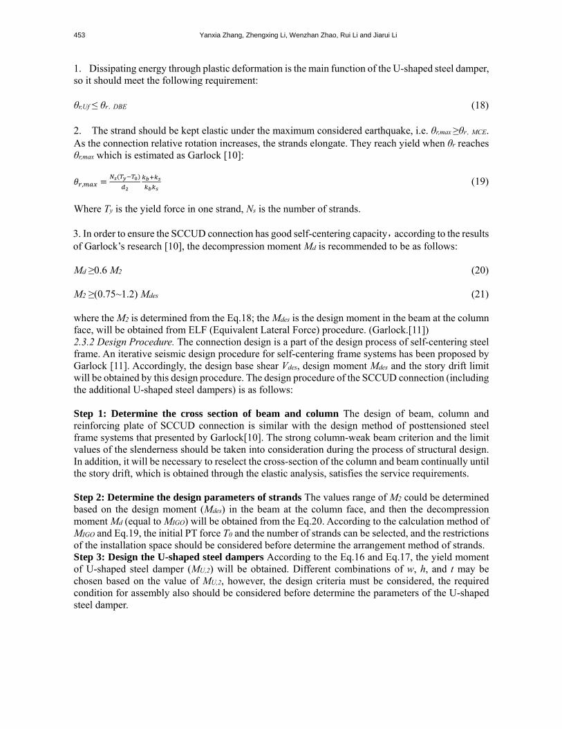
3. TEST SCHEME 3.1 Specimen Design This study designs a SCCUD connection and conducts a test on this connection. Q235B steel is used for the U-shaped steel dampers, while Q345B steel is used for all of the other components. Each U-shaped steel damper has dimensions of 2508010 mm. The ratio of the initial PT force to the ultimate Tu, of the steel strands is 0.2. The column has a cross-sectional dimension of HW 3503501219 mm, and the beam has cross-sectional dimensions of 4502501416 mm. Furthermore, 3M24 grade 10.9 large hexagonal bolts are used to connect the U-shaped steel dampers to the beam flanges. The specification for the steel strands is 1×19-1860; the steel strands have a nominal diameter of 21.6 mm and a nominal area of 312.9 mm2. Figure 8 shows the dimensions of other components and the layout of the steel strands.
Figure 8. Details of the SCCUD Specimen
3.2 Test Setup and Cyclic Loading History Instrumentation The specimen was tested in the setup as shown in Figure 9. The loading device of this test was a frame-type adjustable self-balancing loading system and the photograph has shown in Figure 10. The setup assumed that the column midheight is points of inflection in the SC-MRFs. The column was pinned at the top and base with clevis, which allowed the column ends to rotate freely but restricted the movements in the vertical and horizontal directions. According to the test equipment conditions, the beam loading point was taken to be 2.3 m from the center of the column. The servo actuator at the top of the column was used to emulate the column axial force, with a column axial compression ratio of 0.2. Two 100-t electro-hydraulic servo actuators were used on the two free ends of the cantilever beams for cyclic displacement loading. The cyclic loading history made reference to the AISC 2005, using story drift control loading as follows: (1)0.375% rad,6 cycles; (2)0. 5% rad,6 cycles; (3)0. 75% rad,6 cycles; (4)1% rad,4 cycles; (5)1.5% rad,2 cycles; (6)2% rad,2 cycles; (7)3% rad,2 cycles; (8)4% rad,2 cycles; (9)5% rad,2 cycles.

455 Yanxia Zhang, Zhengxing Li, Wenzhan Zhao, Rui Li and Jiarui Li
Figure 9 Test setup Figure 10 Test photograph 3.3 Instrumentation The instrumentation is illustrated in Figure 11. The column capital is subjected to an axial force by a 600T actuator, and an additional two 100T actuators on the beam ends apply cyclic loadings. Each strand has a force transducer to monitor the PT force. The displacement data for the beam ends is collected by two displacement meters arranged on the top flanges. Linear displacement potentiometers fixed on the junctions of the column flanges and the beams are used to measure the gap width. The column flanges, column stiffeners, top and bottom beam flanges, and vertical and horizontal directions of the beam webs are pasted with strain gauges that measure the strain changes during loading in each position.
Figure 11. Arrangement of Displacement Meter
4. TEST RESULTS 4.1 Hysteretic Behavior and Energy-dissipation Capacity The experimental force-displacement response of the system along with the loading protocol are shown in the Figure 12. At the initial stage of the loading process (i.e. before the opening is generated), the force-displacement relationship is similar to the welded moment connection, and the initial stiffness is 9.7 kN/mm. Figure 13 shows the moment-rotation angle relationship that was obtained from the test. After the gap opens, the stiffness decreases significantly, and the U-shaped steel dampers start to yield, at this time the stiffness of the connection is mainly related to the stiffness of the U-shaped steel dampers and the axial stiffness of the pre-stressed steel strands. After the U-shaped steel dampers have completely yielded, the rotation angle increases rapidly; the rotational stiffness of the connection is mainly determined by the stiffness of the pre-stressed steel strands. After the loading process ends, the residual rotation angle at the opening of the connection (θres) is 0.078%, which indicates that the connection has a relatively good self-centering capacity. During the entire

A Performance Study of Beam Column Connections of Self-Centering Steel Frame with U-Shaped Steel Dampers 456
loading process, the pre-stressed steel strands provide the connection with a self-centering capacity; the U-shaped steel dampers are mainly used to dissipate energy. The energy-dissipation coefficient (βE) is an important index that evaluates the energy-dissipation capacity. According to the definition of βE that was provided by Seo and Sause [12], the value of βE of the connection is calculated to be 0.43.
Figure 12. Experimental Force-displacement response of the Test Specimen
Figure 13. Experimental Moment-rotation response of the Test Specimen
4.2 Change of PT Force The steel strands are placed symmetrically. Therefore, four steel strands on one side are selected to study the change in the PT force during the test. Figure 14 shows the relationship between the PT force and the inter-story drift of one steel strand on the outer side and the relationship between the PT force and the inter-story drift of one steel strand in the middle. T represents the magnitude of the PT force during the test; the yield PT force of the steel strands (Ty) is 540 kN. The figure shows the change in the PT force during the test, and Table 1 lists the analysis results of the PT force. T0 represents the initial PT force of the steel strands; Tr0.2, Tr0.3, Tr0.4 and Tr0.5 represent the force of the steel strands after the loading levels of θ=0.02 rad, θ=0.03 rad, θ=0.04 rad and θ=0.05 rad are completed, respectively, and Tmax represents the maximum PT force during the entire loading process. During seismic loading, the steel strands must maintain their elasticity during the entire process to prevent the structure from losing its load-bearing capacity. Table 1 shows that the value of Tmax of each of the outer strands (strand 1 and 4) is slightly greater than the value of Tmax of each of the strands in the middle (strand 2 and 3). During the test, the maximum PT force is 0.507Ty, and the steel strands remain elastic throughout the test. A comparison between the changes in the PT force at different stages based on the results in Table 1 shows that the PT force decreases by only approximately 10% after the 26 loading cycles before the loading level of θ=0.03 rad is completed, but the maximum ratio of PT force decreased is 30.3% after the last six loading cycles are completed (i.e., after the loading level of θ=0.05 rad is completed). These results indicate that as the inter-story drift increases, the width of the gap opening increases, and the PT force also decreases significantly.
Strand 1 Strand 2 Figure 14. PT Force –Story Drift response of the Test Specimen
Table 1. Experimental Results of PT Force

457 Yanxia Zhang, Zhengxing Li, Wenzhan Zhao, Rui Li and Jiarui Li
Number T0/Ty (T0-Tr0.2)/T0 (T0-Tr0.3)/T0 (T0-Tr0.4)/T0 (T0-Tr0.5)/T0 Tmax/Ty 1 0.217 10.6% 14.9% 22.8% 27.8% 0.507 2 0.218 9.3% 13.4% 19.9% 24.8% 0.498 3 0.216 10.0% 14.3% 21.1% 27.6% 0.495 4 0.215 10.7% 15.8% 22.5% 30.3% 0.502
4.3 Change in the Strain The strain data at key locations are selected for analysis. Figure 15 and Figure 16 show the relationships between the strain and the inter-story drift at several locations, B represents the beam, C represents the column, P represents the flange, W represents the web plate, and BP1 and BP2 are located on the beam flange reinforcing plate. When the inter-story drift reached 0.05 rad, several parts of the column are still in the elastic state, and the plasticity in the beam is still concentrated at the beam flange reinforcing plates (the locations where the beam flange reinforcing plates contact the column flanges) and the beam flanges at the ends of the reinforcing plates. In contrast, the strains at all of the other locations are still lower than the yield strain, which indicates that the connection has good seismic performance.
Figure 15. Strain of Crucial Positons for the Beam of Specimen
Figure 16. Strain of Crucial Positons for the Column of Specimen
5. COMPARISON BETWEEN THE NUMERICAL SIMULATION AND THE TEST 5.1 Model for the SCCUD Connection A finite element model to simulate the test is developed using the Abaqus 6.11 [13]. Solid C3D8R elements are used for the main body of the finite element model, and T3D3 truss elements are used for the pre-stressed steel strands. Figure 17 shows the finite element model and the mesh generation. The Bolt Load function in Abaqus is used to apply pretension to the high-strength bolts. The boundary conditions of the model are the same as those of the test.
Figure 17. Finite Element Model Details and Finite Element Mesh Generation
A Performance Study of Beam Column Connections of Self-Centering Steel Frame with U-Shaped Steel Dampers 458
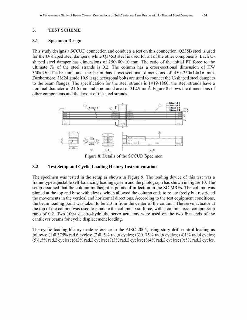
5.2 Comparison between the Numerical Simulation and the Test Figure 18 compares the deformations of the SCCUD connection that were obtained from the test and the finite element analysis under cyclic loading conditions. When the inter-story drift reaches 0.05 rad, the widths of the openings in the test and in the finite element model are 21.93 mm and 21 mm, respectively. When the loading process is completed and the structure returns to the initial position, the widths of the maximum residual openings during the test and in the finite element model are 0.04 mm and 0.03 mm, respectively. The slight difference in the widths of the openings that are generated during the test and simulated using the finite element model is attributed to manufacturing process of the specimen and installation deviation. The results of the finite element analysis are generally consistent with the test results.
story drift θ=5%,gap opening 21.93mm story drift θ=5%,gap opening 21.00mm
loading completed,residual gap opening 0.04mm
loading completed,residual gap opening 0.03mm
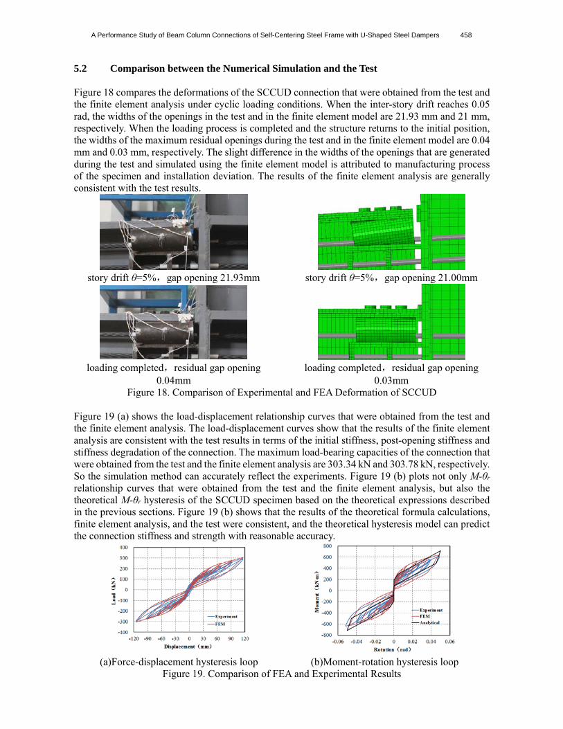
Figure 18. Comparison of Experimental and FEA Deformation of SCCUD Figure 19 (a) shows the load-displacement relationship curves that were obtained from the test and the finite element analysis. The load-displacement curves show that the results of the finite element analysis are consistent with the test results in terms of the initial stiffness, post-opening stiffness and stiffness degradation of the connection. The maximum load-bearing capacities of the connection that were obtained from the test and the finite element analysis are 303.34 kN and 303.78 kN, respectively. So the simulation method can accurately reflect the experiments. Figure 19 (b) plots not only M-θr relationship curves that were obtained from the test and the finite element analysis, but also the theoretical M-θr hysteresis of the SCCUD specimen based on the theoretical expressions described in the previous sections. Figure 19 (b) shows that the results of the theoretical formula calculations, finite element analysis, and the test were consistent, and the theoretical hysteresis model can predict the connection stiffness and strength with reasonable accuracy.
(a)Force-displacement hysteresis loop (b)Moment-rotation hysteresis loop Figure 19. Comparison of FEA and Experimental Results

459 Yanxia Zhang, Zhengxing Li, Wenzhan Zhao, Rui Li and Jiarui Li
6. ANALYSIS OF THE FACTORS THAT AFFECT THE PROPERTIES OF THE SCCUD CONNECTION
The effects of the width, height and thickness of the U-shaped steel damper are considered. Eight other connections of the same type that were used in the test are also designed for comparison. Table 2 lists the detailed parameters of the connection models.
Table 2. Test Matrix
Specimens size (w×h×t) T0/Tu Bolt specification
SCCUD 250�80�10(mm) 0.2 3M24 Grade10.9 SCCUD-W150 150�80�10(mm) 0.2 2M24 Grade10.9 SCCUD-W200 200�80�10(mm) 0.2 3M24 Grade10.9 SCCUD-W300 300�80�10(mm) 0.2 3M24 Grade10.9 SCCUD-W350 350�80�10(mm) 0.2 3M24 Grade10.9 SCCUD-H70 250�70�10(mm) 0.2 3M24 Grade10.9 SCCUD-H100 250�100�10(mm) 0.2 3M24 Grade10.9
SCCUD-T6 250�80�6(mm) 0.2 3M24 Grade10.9 SCCUD-T16 250�80�16(mm) 0.2 3M24 Grade10.9
6.1 Effect of the Width of the U-shaped Steel Damper on the Properties of the Connection To study the effect of the width of the U-shaped steel damper on the connection, the finite element analysis(FEA) results of the SCCUD connection (base-element 250×80×10) are compared with the analysis results of the SCCUD-150, the SCCUD-W200, the SCCUD-W300 and the SCCUD-W350 (Figure 20). The force-displacement curve of each connection is linear, and the stiffness of each connection remains nearly constant before the opening is generated, which further demonstrates that the initial stiffness of the connection is mainly related to the magnitude of the initial PT force. Table 3 lists the main results of the analysis of the five connections. The SCCUD-W150 connection has the lowest load-bearing capacity (246.77 kN), and the SCCUD-W350 connection has the highest load-bearing capacity (346.92 kN); the load-bearing capacities of the connections increase with increasing width of the U-shaped steel damper. The maximum openings of the five connections show that for all but the SCCUD-W150 connection, the width of the gap opening, which occurs when the inter-story drift is largest (0.05 rad), decreases with increasing width of the U-shaped steel damper. The SCCUD-W150 connection has the lowest value of βE and a relatively poor energy-dissipation capacity. With increasing width of the U-shaped steel damper, the values of βE of the SCCUD-W150 , the SCCUD-W200 , the SCCUD-W 300 and the SCCUD-W350 connection are 0.38, 0.44, 0.49 and 0.48, respectively, which indicates that the energy-dissipation capacity of the connection increases with increasing width of the U-shaped steel damper within a certain range. The SCCUD-W300 connection has the highest value of βE and a relatively small maximum opening, which indicates that the SCCUD-W300 connection not only can reduce the deformation of the SC-MRFs but also has reliable energy dissipation capacity. The results of the SCCUD-W350 connection show that a continuous increase in the width of the U-shaped steel damper has no impact on the energy-dissipation capacity of the connection. The widths of the residual openings of the five connections increase with increasing width of the U-shaped steel damper; the width of the residual opening of the SCCUD-W350 connection increases significantly to 0.479 mm, which indicates that an increase in the width of the U-shaped steel damper does not provide any benefits now. Figure 21 shows nephogram of the equivalent plastic strains (PEEQ) in the column panel zone regions of the SCCUD-W300 connection and the SCCUD-W350 connection. When the width of the U-shaped steel damper reaches 300 mm, plasticity occurs in the panel zone. The maximum PEEQ value is 1.98610-3. When

A Performance Study of Beam Column Connections of Self-Centering Steel Frame with U-Shaped Steel Dampers 460
the width of the U-shaped steel damper is increased to 350 mm, the plasticity of the column panel zone increases to 2.95910-3. Therefore, for constant dimensions of the cross sections of the beam and the column, an increase in the width of the U-shaped steel damper within a certain range can improve the load-bearing and energy-dissipation capacities of the connection but also will have a negative impact on the self-centering capacity of the connection.
Table3 FEA Results
Specimens Maximum load
(kN) Maximum gap
opening(mm)Residual gap
opening(mm) energy dissipation
ratio SCCUD -W150 246.77 20.94 0.003 0.26 SCCUD -W200 275.17 22.06 0.038 0.38
SCCUD 303.78 21.00 0.028 0.44 SCCUD -W300 332.80 20.01 0.196 0.49 SCCUD -W350 346.92 18.63 0.479 0.48
(a)SCCUD and SCCUD-W150 (b)SCCUD and SCCUD-W200
(c)SCCUD and SCCUD-W300 (d)SCCUD and SCCUD-W350
Figure 20. Comparison of Force-displacement Response for SCCUD ~ SCCUD-W350

461 Yanxia Zhang, Zhengxing Li, Wenzhan Zhao, Rui Li and Jiarui Li
(a)SCCUD-W300 (b)SCCUD-W350
Figure 21. Nephogram of the PEEQ in the Column Panel Zone
6.2 Effect of the Height of the U-shaped Steel Damper on the Properties of the Connection
The height of the U-shaped steel damper is limited by the height of the beam web and the arrangement of the steel strands. To study the effect of the height of the U-shaped steel damper on the behavior of the connection, finite element analyses are conducted on the SCCUD-H70 and the SCCUD-H100. Figure 22 (a) compares the hysteretic curves of the SCCUD connection and the SCCUD-H70 connection. To conveniently observe the regular pattern, Figure 22 (b) compares the hysteretic curves of the SCCUD-70 and the SCCUD-H100. The results show that even a 30 mm difference in the height of the U-shaped steel damper causes a relatively small change in the stiffness after the gap opens and no significant change in the hysteretic loops. The main analysis results that are shown in Table 4 demonstrate that the maximum load-bearing capacity of the joint gradually decreases from 317.28 kN to 283.86 kN with increasing height of the U-shaped steel damper and that the decrease is significant. The maximum widths of the gap openings of the SCCUD-H70, the SCCUD and the SCCUD-H100 are 20.52 mm, 21 mm and 19.87 mm, respectively. Thus, there is little difference in the widths of the largest openings in these three joints; therefore, a change in the height of the U-shaped steel damper has a relatively small impact on the width of the largest opening of the connection. In terms of the energy-dissipation capacity, the value of βE decreases gradually from 0.48 to 0.46 with increasing height of the U-shaped steel damper. The SCCUD-H70 connection has a higher load-bearing capacity and a higher energy-dissipation capacity than the SCCUD-H100 and the SCCUD (base-element 250×80×10) connection. The SCCUD-H70, the SCCUD-H100 and the SCCUD connection all have very small residual openings; the width of the residual gap opening increases with decreasing height of the U-shaped steel damper. However, due to the spatial requirements of the structure, the height of the U-shaped steel damper is generally not small enough to affect the closing of the gap.

A Performance Study of Beam Column Connections of Self-Centering Steel Frame with U-Shaped Steel Dampers 462
(a)SCCUD and SCCUD -H70 (b)SCCUD -H70 and SCCUD -H100 Figure 22. Comparison of Force-displacement Response for SCCUD,SCCUD-70、SCCUD-
H100
Table 4. FEA Results
Specimens Maximum load
(kN) Maximum gap
opening(mm)Residual gap
opening(mm) energy dissipation
ratio SCCUD-H70 317.28 20.52 0.1225 0.48
SCCUD 303.78 21.00 0.0277 0.44 SCCUD-H100 283.86 19.87 0.0008 0.36
6.3 Effect of the Thickness of the U-shaped Steel Damper
on the Behavior of the Connection To study the thickness of the U-shaped steel damper on the behavior of the connection, finite element analyses are conducted on the SCCUD-T6 and the SCCUD-T16 connection. Figure 23 compares the hysteretic curves of the SCCUD-T6, the SCCUD (base-element 250×80×10) and the SCCUD-T16 connection. The results show that the initial stiffness of the connection is mainly controlled by the initial pre-stress of the steel strands; therefore, a change in the thickness of the steel plate of the U-shaped steel damper has little impact on the initial stiffness of the connection and the magnitude of the imminent gap opening load. There is a relatively large difference in the post-opening stiffness of the connection, which is mainly due to the fact that the elastic stiffness of the U-shaped steel damper increases with increasing thickness of the steel plate. The post-opening stiffness of the SCCUD-T6 connection decreases significantly compared to that of the SCCUD connection, whereas the post-opening stiffness of the SCCUD-T16 connection increases significantly. Table 5 lists the main analysis results. The load-bearing capacity of each connection increases with increasing thickness of the steel plate of the U-shaped steel damper. The maximum openings of the SCCUD-T6 and the SCCUD connection are 20.56 mm and 21.00 mm, respectively; thus, there is essentially no change in the width of the maximum opening. In contrast, the maximum opening of the SCCUD-T16 connection decreases significantly (17.66 mm), which indicates that for constant dimensions of the cross sections of the beam and column, the opening of the gap decreases significantly with increasing thickness of the steel plate of the U-shaped steel damper (t) when thickness is equal and greater than 10 mm. Moreover, the width of the residual opening increases significantly with increasing t, and the value of βE of the joint also increases with increasing t, but the increase is insignificant. In addition, when t=16 mm, the maximum PEEQ value of the SCCUD-T16 connection reaches 1.03410-2 (as shown in the nephogram of the PEEQ in the column panel zone region of the SCCUD-T16 connection in Figure 24), and a relatively large degree of plasticity develops. Therefore, an increase in the thickness of the U-shaped steel damper will cause significant increases in the load-bearing capacity and post-opening stiffness of the connection. However, for constant dimensions of the cross sections of the beam and the column, an increase in the thickness of

463 Yanxia Zhang, Zhengxing Li, Wenzhan Zhao, Rui Li and Jiarui Li
the U-shaped steel damper will not significantly improve the energy-dissipation capacity of the connection. An excessively thick U-shaped steel damper will affect the self-centering capacity of the connection and also increase the plastic development of other components, such as the beam and the column.
Figure 23. Comparison of Force-displacement
Response for SCCUD、SCCUD-T6 and SCCUD-T16
Figure 24. Nephogram of the PEEQ in the Column Panel Zone of the SCCUD-T16 Connection
Table 5. FEA Analysis Results
Specimens Maximum load
(kN) Maximum gap
opening(mm)Residual gap
opening(mm)energy dissipation
ratio SCCUD-T6 258.74 20.56 0.0021 0.28
SCCUD 303.78 21.00 0.0277 0.44 SCCUD-T16 358.44 17.66 1.3132 0.48
7. CONCLUSIONS This study proposes a new type of self-centering beam-column connection with U-shaped steel damper for steel SC-MRFs. A simplified connection hysteresis model was developed using simple mechanics, and an iterative seismic design procedure for SCCUD connection was presented. The test of the proposed connection is simulated using the Abaqus 6.11 finite element software. After verifying the feasibility of the numerical simulation method, this study analyzes the influencing parameters using nine FEA model and investigates the effects of the width, height and thickness of the U-shaped steel damper on the connection. The following conclusions are obtained: 1. The SCCUD connection for steel SC-MRFs can realize the self-centering mechanism. Under cyclic loads, the U-shaped steel damper dissipates energy through plastic deformation and has good energy-dissipation capacity. 2. The width of the U-shaped steel damper has a relatively large impact on the behavior of the connection. Increasing the width of the U-shaped steel damper can significantly improve the load-bearing capacity, the post-opening stiffness and the energy-dissipation capacity of the connection but also has a negative impact on the self-centering capacity. An increase in the width of the U-shaped steel damper beyond a certain limit will not further improve the behavior of the connection but will decrease the self-centering capacity of the connection and increase plastic damage to other components. It is recommended to firstly change the width of the U-shaped steel damper to improve the energy-dissipation capacity of the connection.

A Performance Study of Beam Column Connections of Self-Centering Steel Frame with U-Shaped Steel Dampers 464
3. The height of the U-shaped steel damper has a relatively small impact on the behavior of the connection. The height of the U-shaped steel damper is limited by the height of the beam web and the arrangement of the steel strands. Therefore, changing the height of the U-shaped steel damper is not recommended for improving the behavior of the connection. 4. The thickness of the steel plate of the U-shaped steel damper has a relatively large impact on the load-bearing capacity and post-opening stiffness. The load-bearing capacity and post-opening stiffness will be increased with the thicker steel plate of the U-shaped steel damper. However, for constant dimensions of the cross section of the beam and the column, changing the thickness of the U-shaped steel damper will not significantly improve the energy-dissipation capacity of the connection. An excessively thick U-shaped steel damper will weaken the self-centering capacity of the connection and also increase the plastic development of other components. 5. Compared with the experimental and FEA results, theoretical hysteresis model proved to have reasonable accuracy in the prediction of the connection stiffness and strength.
ACKNOWLEDGMENTS The research reported herein is supported by the National Natural Science Foundation of China under Grant No. 51278027, National Key Project of Research and Development Plan of Key Technology in Design of Industrialized Buildings of China under Grant No. 2016YFC0701500 and Project of Constructing Beijing Energy Saving and Emission Reduction Technology Collaborative Innovation Center.
REFERENCES [1] Garlock, M.M. and Ricles, J.M., et al., “Post-tensioned Seismic Resistant Connections for
Steel Frames//Structural Stability Research Council Conference Workshop, Rolla Missouri: Structural Stability Research Council, 1998.
[2] Ricles, J.M., Sause, R., Peng, S. and Lu, L., “Experimental Evaluation of Earthquake Resistant Post-tensioned Steel Connections" Journal of Structural Engineering, 2002, Vol. 128, No. 7, pp. 850–859.
[3] Garlock, M.M., Ricles, J.M. and Sause, R., “Cyclic Load Tests and Analysis of Bolted Top-and-seat Angle Connections”, Journal of Structural Engineering, 2003, Vol. 129, No. 12, pp. 1615–1625.
[4] Christopoulos, C., Filiatrault, A., Uang, C.M. and Folz, B., “Post-tensioned Energy Dissipating Connections for Moment-resisting Steel Frames”, Journal of Structural Engineering, 2002, Vol. 128, No. 9, pp. 1111–1120.
[5] Cruz, P.R., “Analysis, Design, and Evaluation of Post-tensioned Friction Damped Connections for Steel Moment Resisting Frames”, Bethlehem, Pennsylvania: Lehigh University, 2003.
[6] Iyama, J., Seo, C.Y., Ricles, J.M. and Sause, R., “Self-centering MRFs with Bottom Flange Friction Devices under Earthquake Loading”, Journal of Constructional Steel Research, 2009, Vol. 65, pp. 314–325.
[7] Wolski, M., Ricles, J.M. and Sause, R., “Experimental Study of a Self-centering Beam–column Connection with Bottom Flange Friction Device”, Journal of Structural Engineering, 2009, Vol. 135, No. 5, pp. 479-488.
[8] Lin, Y.C., Ricles, J.M. and Sause, R., “Earthquake Simulations on Self-centering Steel Moment Resisting Frame with Web Friction Devices”, Structures Congress 2009, Reston Virginia: American Society of Civil Engineers, 2009.

465 Yanxia Zhang, Zhengxing Li, Wenzhan Zhao, Rui Li and Jiarui Li
[9] Rojas, P., “Seismic Analysis, Design, and Evaluation of Post-tensioned Friction Damped Connections for Steel Moment Resisting Frames”, Department of Civil and Environmental Engineering: Lehigh University, 2003.
[10] Garlock, M.M., Sause, R. and Ricles, J.M., “Behavior and Design of Posttensioned Steel Frame Systems”, Journal of Structural Engineering, 2007, Vol. 133, No. 3, pp. 389-399.
[11] Garlock, M.M., “Full-scale Testing, Seismic Analysis, and Design of Post-tensioned Seismic Resistant Connections for Steel Frames”, Civil and Environmental Engineering Dept., Lehigh University, 2002.
[12] Seo, C.Y. and Sause, R., “Ductility Demands on Self-centering Systems under Earthquake Loading, ACI Structural Journal, 2005, Vol. 102, No. 2, pp. 275–85.
[13] Abaqus Documentation. ABAQUS Analysis User’s Manual, 2011.