a piezoelectric wafer-stack vibration energy harvester for ... · a piezoelectric wafer-stack...
TRANSCRIPT

A piezoelectric wafer-stack vibration energy harvester for wireless sensor networks
Xuezheng Jiang*, Yancheng Li, Jianchun Li Centre for Built Infrastructure Research, Faculty of Engineering and Information Technology,
University of Technology Sydney, NSW 2007, Australia
ABSTRACT
Over the past few decades, wireless sensor networks have been widely used in civil structure health monitoring application. Currently, most wireless sensor networks are battery-powered and it is costly and unsustainable for maintenance because of the requirement for frequent battery replacements. As an attempt to address such issue, this paper presents a novel piezoelectric vibrational energy harvester to convert the structural vibration into usable electrical energy for powering wireless sensor networks. Unlike the normal canti lever beam structure, the piezoelectric harvester presented in this paper is based on the wafer-stack configuration which is suitable for applications where large force vibration occurs, and therefore can be embedded in civil structures to convert the force induced by vibration of large structures directly into electrical energy. The longitudinal mode of the piezoelectric wafer-stack was developed firstly to illustrate the force-to-voltage relationship of piezoelectric materials and to find the inter-medium force that will be used to convert vibration energy into electrical energy. Then, two electromechanical models (without and with a rectified circuit), considering both the mechanical and electrical aspects of the harvester, were developed to characterize the harvested electrical power under the external load. Exact closed-form expressions of the electromechanical models have been derived to analyze the maximum harvested power and the optimal resistance. Finally, a shake table experimental testing was conducted to prove the feasibility of the presented piezoelectric-wafer-stack harvester under standard sinusoidal loadings. Test results show that the harvester can generate a maximum 45mW (AC) or 16mW (DC) electrical power for sinusoidal loading with 40mm amplitude and 2Hz frequency, and the harvested electrical power is proportional to the levels of exciting vibrational loading.
Keywords: Vibration energy harvesting, piezoelectric, wafer-stack, electromechanical model
1. INTRODUCTION
Because of the advantages over existing wired technologies, wireless sensors and sensor networks have become ubiquitous in the field of structural health monitoring. Currently, most wireless electronics are battery-powered and it is not only costly for maintenance but the requirement for frequent battery replacements raises serious reliability and sustainability issues in practice. The task of replacing battery sometimes can become extremely difficult, especially in case of structural health monitoring applications, where there are hundreds and thousands of sensors that are often installed during construction stages. For these sensors, if it is not impossible, for the least it is impractical to gain access, remove protection and replace batteries. Although the power requirement of a single wireless is quite low, the wireless sensor network required significant power supply since the number of the sensor nodes and the computational demands have drastically increased due to advanced algorithms to enable performance of structural health monitoring' , especially for large-scale civil infrastructures. So it is of great necessity to seek alternative power sources for the sensor networks. Due to the low-power consumption requirements of an individual wireless sensor, a possible solution to this problem is the technologies that enable harvesting ambient vibrational energy to power wireless sensor networks 1
•2
•
Obtaining power from ambient vibration sources is generally known as vibrational energy harvesting, or vi brational energy scavenging. Several methods, such as electromagnetic induction, electrostatic generation, and piezoelectric generation, can be utilized to harvest electrical energy from external vibrations3
• While each of the aforementioned methods can generate a useful amount of energy, piezoelectric materials have received more attentions especially in the recent years due to their ability to directly convert applied strain energy into usable electrical energy, as well as its large power density, and ease ofapplication4
•6
• Comparing to energy harvesting for large-scale alternative energy generation
*[email protected]; phone +61 2 9514 2403; fax +61 2 9514 2435
Sensors and Smart Structures Technologies for Civil , Mechanical , and Aerospace Systems 2013, edited by Jerome Peter Lynch, Chung-Bang Yun, Kon-Well Wang , Proc. of SPIE Vol. 8692,
869246 · © 2013 SPIE · CCC code: 0277-786X/13/$18 · doi: 10.1117/12.2009630
Proc. of SPIE Vol. 8692 869246-1
Downloaded From: http://opticalengineering.spiedigitallibrary.org/ on 06/10/2014 Terms of Use: http://spiedl.org/terms
using wind turbines and solar cells is mature technology, the development of energy harvesting technology by using piezoelectric devices on a scale appropriate for small, low-power, embedded wireless sensing systems is still in its developmental stage, particularly for application of structural health monitoring sensing system. In 2002, Elvin et al. proposed a self-powered damage detection sensor using piezoelectric patches7
• A piezoelectric harvester in cantilever beam configuration is utilized to convert the applied load into electricity and provide a power for the sensors in order to measure the strain and to send the results to a moving cart. In 2006, Discenzo et al. developed a prototype self-powered sensor node that performs sensing, local processing, and telemeters the results to a central node for pump condition monitoring applications8
. The device was mounted on an oil pump, and a cantilever piezoelectric beam tuned to the excitation frequency was embedded with the sensor node to scavenge energy from the pump vibration. The test results showed that the output power could reach to 40mW. In 2008, Lallart et al. proposed a self-powered wireless structural health monitoring system9
. A piezoelectric harvester based on the beam structure, using the synchronized switch harvesting method, was utilized to convert ambient mechanical energy into electricity and powered the structure health monitoring system. In 2011, Kim et al. investigated the possibility of harvesting energy from bridges by converting the potential energy of vibrating bridge systems into electrical energy using a cantilever piezoelectric harvester, and got some good results 10
• Of the published results that focus on using piezoelectric harvesters scavenging electricity for the wireless sensor networks, most of them have focused on harvesting energy using cantilever beams configuration 11
.13
•
However, the cantilever beam cannot sustain large force, and in large force vibration environments, such as in the heavy manufacture equipment or in large operating machinery, the piezoelectric harvester in cantilever beam configuration would be more frangible and breakable.
In this paper, a novel piezoelectric harvester was developed to scavenge energy from surrounding vibrations in order to provide power for the wireless sensor networks. The piezoelectric material used in this novel harvester is constructed in wafer-stack configuration that is robust and suitable for large force vibrations existing in the civil structural applications. In comparison with the monolithic configuration, the stack structure can reduce the voltage output and the matching resistive load of the harvester to a more manageable level 14
, therefore the piezoelectric stack is selected in this research to scavenge vibration energy. By now, the development of models for cantilevered piezoelectric harvester has attracted a great deal of attentions from researchers. And there are already many models available to evaluate the harvested power of cantilevered harvester15
•17
• However, not much research has been reported on modeling wafer configuration harvester for the large force vibration. Moreover, a piezoelectric harvester system contains two fundamental elements: the mechanical part that generates electrical energy, and an electrical circuit that converts and rectifies the generated energy in a form of an alternating voltage, into a constant voltage. The efficiency of the energy harvester design depends not only on the piezoelectric harvester itself but also on its integration with the electrical circuit. Therefore, an electromechanical model is of great importance to optimize the design as well as for understanding the behavior of the piezoelectric harvester.
In this paper, we will firstly investigate the longitudinal mode of the piezoelectric wafer-stack for the aim of finding the inter-medium force that will be used to convert vibration energy into electrical energy. Then, two electromechanical models (without and with a rectified circuit) of this novel piezoelectric wafer-stack harvester will be presented to investigate the ability of harvesting electrical power and find the optimal condition for maximizing electrical power output. Finally, we will present a series of tests conducted to verify the theoretical findings. Test results show that the proposed electromechanical model for the piezoelectric wafer configuration harvester is accurate and the harvester can generate up to 45mW (AC) or 16mW (DC) electrical power during the sinusoidal motion of2 Hz.
2. ELECTROMECHANIAL MODEL
2.1 Electrical characteristics of the piezoelectric wafer-stack
The piezoelectric vibration energy harvester proposed in this paper is aimed at large force vibration condition, such as in most of civil engineering applications. The wafer-stack configuration is chosen due to its durability for large exciting force and its advantage on power generation over single piezoelectric monolithic element. When subjected to an external force, the piezoelectric wafer-stack will produce an electric charge and convert external kinetic energy into electricity. Therefore, the piezoelectric wafer-stack is the media to convert kinetic energy to electrical energy and it is necessary to investigate the electrical reaction of the wafer-stack under external excitation before developing an accurate model to present a piezoelectric harvester. Figure I shows the sketch of the piezoelectric wafer-stack under applying external force. The piezoelectric wafer-stack is made up of 36 piezoelectric wafers, which are assembled mechanically in series but electrically in parallel. The wafers are polarized along their thickness so that they exhibit a piezoelectric effect only
Proc. of SPIE Vol. 8692 869246-2
Downloaded From: http://opticalcnginccring.spicdigitallibrary.org/ on 06/10/2014 Terms of Use: http: //spiedl.org/tcrms

in their thickness direction. The wafer-stack is 20 mm square and 34 mm height. The force, F(t), used in this analysis is a sinusoidal excitation in order to simplifY the analysis.
+t • F • Xp Electrode
+. .. t'tezoe ectnc wa er
F(t) hp :n
Wafer-stack '----- •
TF,xp +
VfJ -Figure I. Construction of the piezoelectric wafer-stack Figure 2. Longitudinal mode of the piezoelectric stack
According to the IEEE Standard on Piezoelectricity: under the external force, giving by the strain S, stress T, electric field E, and electric displacement D, the constitutive relations of the piezoelectric energy harvesting device are typically defined by:
(I)
where the e is the piezoelectric coefficient, cE is the elastic stiffness constant under a constant electric field, and e' is the dielectric constant under constant strain. Note that the subscripts of the state variables show that all constitutive qualities are generated and applied on the thickness direction of the piezoelectric material.
Figure 2 shows the electrical characteristics of the PIEZOELECTRIC wafer-stack, and it needs to point out that the polarization direction of each wafer is opposite to each other. For the configuration as shown in figure 2, the constitutive equations of the piezoelectric wafer-stack can be written as:
~ = FjA , (2)
where xp is the strain of the piezoelectric wafer-stack under the external force; VP is the output voltage of the wafer-stack; Q is the electric charge; A is the cross-section area of the wafer-stack, and h is the length of the wafer-stack. To simplifY the analysis, we assume the length of the stack is equal to the entire thickness of all the piezoelectric wafers (h =nt) with identical dimension, where n and tare the number and thickness of a single piezoelectric wafer, respectively. According to the relationship in equation (2), the constitutive equations of the piezoelectric wafer-stack from equation (1) can be rewritten as:
(3)
It can be found from equation (3) that the VP is generated by the external force . The force applied to the piezoelectric disc without any electrical input can produce deformation Xp, the relationship of which is regarded as the elastic coefficient kp of the mechanical characteristic. Piezoelectricity also possesses an electrical propetiy between the voltage and the electric charge, which can be modeled as a capacitor Cr The electromechanical conversion coefficient N is defined as the electromechanical coupling coefficient. Therefore, from equation (3), the force, F., which is actually used to generate electrical voltage, can be written as:
(4)
Equation (4) gives an explicit relationship of vibration force and output voltage, which will be used to build the electromechanical model of the piezoelectric harvester.
Proc. of SPIE Vol. 8692 869246-3
Downloaded From: http://opticalengineering.spiedigitallibrary.org/ on 06/10/2014 Terms of Use: http://spiedl.org/terms

2.2 Electromechanical model without a rectified circuit
Figure 3. Electromechanical model without a rectified circuit
The proposed piezoelectric wafer-stack harvester is a mechanical-and-electrical-system which has the ability to convert vibration kinetic energy into useful electrical energy, so the mathematic model of the harvester should consider not only mechanical but also electrical aspects. Considering these elements and the electrical characteristics of the piezoelectric wafer-stack under the external force, the schematic of the electromechanical model without a rectified circuit is illustrated in figure 3. The governing equations of the system can be written as:
lmPxP +chip +khxp +kPxP +F.= F(t)
. . VP -NxP +CPV1, +-= 0
R
(5)
where mP and kp are the mass and elastic coefficient of the piezoelectric wafer-stack, respectively; ch and kh are the mechanical damping and elastic coefficient of the harvester, respectively; 1 is the output current of the harvester; a resistor Rp connected to the Cp in parallel represents the electric loss property of the piezoelectric material; R1 is the resistance of the external load; R is the equivalent resistance of two parallel resistances Rp and R1• In general, the Rp is much higher than the load resistance, so that R ;:::: R1•
Transforming equation (5) into the frequency domain and dividing the first equation by mP and the second equation by Cp, we obtain:
(6)
Here w is the angular frequency of the vibration; Xp(w), Vp(w) and F(w) are the frequency counterparts of Xp, ~'and F(t). And the natural frequency of the piezoelectric wafer-stack harvester, Wn. and the damping factor G, are defined as:
(7)
Solving equation (6), we can obtain:
1
(l+'Paj)C F(w) X (w)= P
p ~
V (w) = 'PNaF(w)j p ~
(8)
and tV, a and~ can be defined as:
Proc. of SPIE Vol. 8692 869246-4
Downloaded From: http://opticalengineering.spiedigitallibrary.org/ on 06/10/2014 Terms of Use: http://spiedl.org/terms
where 'I' is the dimensionless frequency ; a is the normalized electrical resistance; " is the alternative electromechanical coupling coefficient and can be defined as:
( 10)
Based on equation (8), the electrical power generated by the harvester can be written as:
VP.v; 't' 2 ~F(w)2 aw" P. - -- - ___ ...:.......;'-:------":,---1- 2R -2(kP+kh)(A2 +B2
) (II)
where A= 1- '1' 2 - 2'1' 2 ( ha , B= 't'(a~ +a- a'¥2 + 2(h)
From the equation (II), it can be seen that the electrical power, harvested by the piezoelectric wafer-stack harvester, depends on the external characteristics (frequency 'I' and amplitude F) , the natural frequency Wn. the mechanical damping factor c;h , the normalized electrical load a , the overall stiffness of the harvester (kp+kh) and the overall electromechanical coupling coefficient of the harvester "· At the same time, only the piezoelectric wafer-stack deforms and the mechanical structure of the harvester doesn ' t change its shape when subjected to the external force. Therefore, ch and kh can be set to zero in this piezoelectric wafer-stack harvester. In this case, the maximum harvested electrical power of the harvester and the optimal resistance can be calculated as:
1- '1' 2 F( w)2 N 2 '¥ w R = and P = "
opt ! (~ +J-'¥2)CpaJ max i 4Cpk~ (l-'f' 2 )(~ +}-'f' 2) (12)
Equation (12) shows that the maximum harvested electrical power is proportional to the square of the applied force and inverse proportional to the capacitance of the piezoelectric wafer-stack. Also the optimal external resistance condition for the maximum power is not a constant value and it will change with the piezoelectric material property and the external vibration condition. But for a weakly electromechanical coupling coefficient, the optimal resistance can be simplified as 1/Cpw.
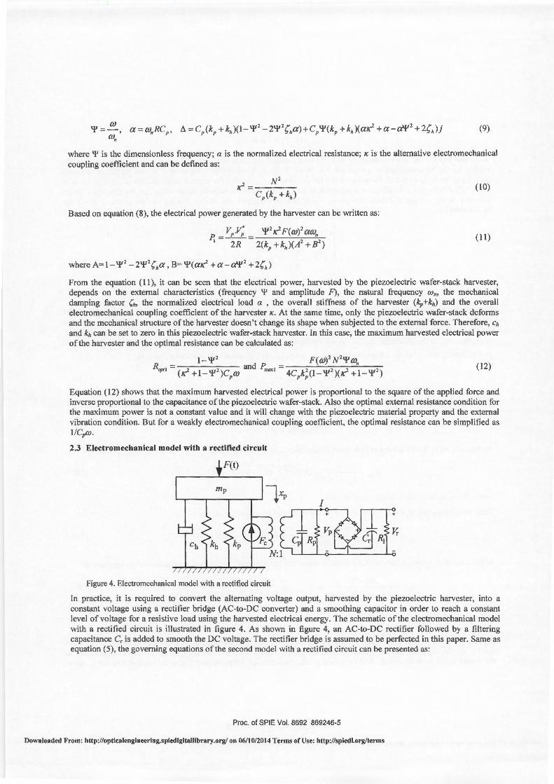
2.3 Electromechanical model with a rectified circuit
Figure 4. Electromechanical model with a rectified circuit
In practice, it is required to convert the alternating voltage output, harvested by the piezoelectric harvester, into a constant voltage using a rectifier bridge (AC-to-DC converter) and a smoothing capacitor in order to reach a constant level of voltage for a resistive load using the harvested electrical energy. The schematic of the electromechanical model with a rectified circuit is illustrated in figure 4. As shown in figure 4, an AC-to-DC rectifier followed by a filtering capacitance C, is added to smooth the DC voltage. The rectifier bridge is assumed to be perfected in this paper. Same as equation (5), the governing equations of the second model with a rectified circuit can be presented as:
Proc. of SPIE Vol. 8692 869246-5
Downloaded From: http://opticalengineering.spiedigitallibrary.org/ on 06/10/2014 Terms of Use: http://spiedl.org/terms

{m)cp +c~:XP .+khxp ~kPxP :F.= F(l)
NxP +CP~' +1 -0 (13)
With regard to the DC output voltage on R1, if the time constant R1Cr is much larger compared to the vibration period, the voltage V, can be considered as a constant. As shown in figure 4, when IVPI is lower than V" the rectifier is an open circuit and the I and Q is null. However, when the I Vp l reaches V" the rectifier starts to work and the I Vpl is kept equal to the rectified voltage V,. Finally, the conduction in the rectifier diodes is blocked again when the absolute value of the harvester output voltage I VPI starts decreasing. Upon the above analysis, the current flowing into the rectified circuit can be calculated as:
. v if vp = v, C,~ +-.!...
R,
. v if vp = v, 1= - C V _ _!_ (14)
r r R,
0 if\VPi < V
From equation (13) and equation (14), it can be found that the harvester output voltage Vp varies proportionally with respect to the piezoelectric wafer-stack strain Xp if the rectifier bridge is blocked and the outgoing current is zero. Let T=2nlw be the period of the vibration, and 11 and 12 be two time instants Ctr 11=T/2), such that the strain Xp goes from the
minimum - Xpm to the maximum Xpm (Xpm is the constant magnitude of the strain). Assume that riP ~ 0 during the semi
period from t1 to 12• Therefore, the integration of the second part of equation (13) from time 11 to t2 is
TV -2Nx +2C V +--=0 pm pr 2R,
Based on equation (15), the rectified voltage V, can be expressed as a function of the strain amplitude Xpm :
V = 2mNR, x r 2mCpRI +JZ' pm
At the same time, from equation (8) the strain magnitude Xpm can be calculated as:
x pm = ~m 2 ~('f' aB + A)2 + ('f' a A- B)2
kP(A +B)
where Fm is the magnitude of the exciting force .
Therefore, the electrical power scavenged by the harvester can be expressed as:
~= 4F,;'f' 1N1m"a 1 [('f'aB+ A)1+('f'aA-B)1] CP k; (A1 +B2
)2 {2'f'a+1Z')
(15)
(16)
( 17)
(18)
In this case, the maximum harvested electrical power of the harvester and the optimal resistance can be expressed as:
( 19)
1- 'f' 2 where .l.= _
2 2 •
"+1-'f'
Equation (19) shows that there is also an optimal resistance, on which the DC electrical power harvested by the harvester reaches maximum value, and the optimal external resistance condition for the maximum power is not a constant value in the model with a rectifier circuit. And for a weakly electromechanical coupling coefficient, the optimal resistance can be
Proc. of SPIE Vol. 8692 869246-6
Downloaded From: http://opticalengineering.spiedigitallibrary.org/ on 06/10/2014 Terms of Use: http://spiedl.org/terms

simplified as n/2Cpw in this model. Also, compared equation (19) to equation (12), it can be found that adding the rectifier circuit causes an increase in the optimal resistance, but the maximum harvested power decreases with the rectifier circuit.
3. EXPERIMENTAL TESTING
A prototype of the piezoelectric wafer-stack harvester was designed and fabricated to examine and verify the theoretical findings. The test setup is shown in figure 5. The harvester was installed in a host-structure. One side of the hoststructure is fixed on the ground and another side is connected to the shaker table. During the test, the shake table loaded the outer-spring 50mm as pre-compression, and then performed different sine movements. And input frequency of the shaker table is set at 2 Hz in order to investigate the power harvesting ability of the proposed harvester under lowfrequency vibration, which typically exists in civil structures. Outer-spring, as shown in figure 5, was used to transfer the vibration force and compress the PIEZOELECTRIC wafer-stack harvester. The stiffness of outer-spring is 34N/mm. Data acquisition system was used to record the output voltage signal of the harvester.
Wafer-stack Outer-spring Hoster
Vibration .. ..
Figure 5. Piezoelectric wafer-stack harvester test setup
Figure 6 shows the relationships between the output AC voltage/power, without the rectifier circuit, and the external resistance under the vibrations with different amplitudes, i.e. lOmm, 20mm, 30mm and 40mm, and fixed vibration frequency , 2Hz. From figure 6, it can be seen that: (1) all the output AC voltages, within a certain range of external resistance, increase with the value of external resistor, and then trend to constants after the external resistance exceeding a certain value; (2) there is an optimal resistance, about 600kQ, with which all the AC powers, generated by the piezoelectric wafer-stack harvester under the vibrations with different amplitudes and fixed vibration frequency, reach to maximum values. At the same time, the maximum harvested AC power increases, from 2mW to 45mW, when the vibration amplitudes increase from lOmm to 40 mm.
90
eo
70
60
~ " 50 00 5 0 40 >
3J
--+- IOmm
-<)-- 20mm
····0 ····· 30mm B " g ·- Amphtude mcrease
-El- 40mm o ·· 0.0 ..... ····O ·O ·
.
~-r-Bfi o·
..13.00 ~--0----0-E>----.,-'~
;' ,/(/
600 IIJJ l(DJ 1200 1400 1600 111JJ 200J
Resistance (kn)
0.05,~-~i-~~---r-;=====::::;-,
/'$ 'K.
0045
0.04
0035
~ 0.03
~ 0025 0 0- 0.02
O.DIS
IOmm
' "'" -EI- 20mm
/
A1
wphtud increase Y....
---0-- 30mm
i ' .Q .i .oo oo .. t _O O···o ...
of;) ···o-.... ,0 Q ·o ....
40mm
,..g---&-G=_ro _, ~~ ~--G~----
600 IIJJ I 000 1200 1400 1600 IIIJJ 200J
Resistance (kn )
Figure 6. Harvested AC voltage/power comparison under different amplitudes
Proc. of SPIE Vol. 8692 869246-7
Downloaded From: http://opticalengineering.spiedigitallibrary.org/ on 06/10/2014 Terms of Use: http://spiedl.org/terms
60
50
~ 40
" ff:JJ 0 >
20
---&-
-v· ····-o···
20mm
30mm
400 ~ ~ 1~ 1~ 1~ 1~ 1~
Resistance (kn)
§: il
"' 0 ~
0.02r;::=====:::::;-~-~~~~-~-~
0018 -B- 20mm
:::: ~-0 .. . 40mm y· .. ·~m~u~2ncr~~s~ 0 ·o E>- 30mm 1 0.012 o··v 001 <:i
O!DI (j ~· Ef3 ~~-~-~-(7---~-~
0.006 v _r-..-0 {!) (,)"'
0.004~ ....... ,.., ~ 0002F.
~ ~ ~ ~ 1~ 1~ 1~ 1~ 1~
Resistance (kn)
Figure 7. Harvested DC voltage/power comparison under different amplitudes
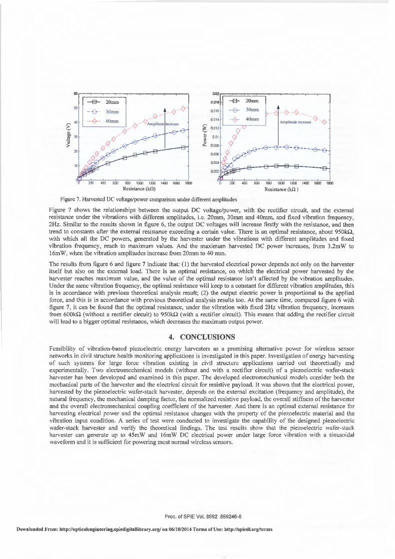
Figure 7 shows the relationships between the output DC vo ltage/power, with the rectifier circuit, and the external resistance under the vibrations with different amplitudes, i.e. 20mm, 30mm and 40mm, and fixed vibration frequency , 2Hz. Similar to the results shown in figure 6, the output DC voltages will increase firstly with the resistance, and then trend to constants after the external resistance exceeding a certain value. There is an optimal resistance, about 950kn, with which all the DC powers, generated by the harvester under the vibrations with different amplitudes and fixed vibration frequency, reach to maximum values. And the maximum harvested DC power increases, from 3.2mW to 16mW, when the vibration amplitudes increase from 20mm to 40 mm.
The results from figure 6 and figure 7 indicate that: (I) the harvested electrical power depends not only on the harvester itself but also on the external load. There is an optimal resistance, on which the electrical power harvested by the harvester reaches maximum value, and the value of the optimal resistance isn't affected by the vibration amplitudes. Under the same vibration frequency, the optimal resistance will keep to a constant for different vibration amplitudes, this is in accordance with previous theoretical analysis result; (2) the output electric power is proportional to the applied force, and this is in accordance with previous theoretical analysis results too. At the same time, compared figure 6 with figure 7, it can be found that the optimal resistance, under the vibration with fixed 2Hz vibration frequency, increases from 600kn (without a rectifier circuit) to 950kQ (with a rectifier circuit). This means that adding the rectifier c ircuit will lead to a bigger optimal resistance, which decreases the maximum output power.
4. CONCLUSIONS
Feasibility of vibration-based piezoelectric energy harvesters as a promising alternative power for wireless sensor networks in civil structure health monitoring applications is investigated in this paper. Investigation of energy harvesting of such systems for large force vibration existing in civil structure applications carried out theoretically and experimentally. Two electromechanical models (without and with a rectifier circuit) of a piezoelectric wafer-stack harvester has been developed and examined in this paper. The developed electromechanical models consider both the mechanical parts of the harvester and the electrical circuit for resistive payload. It was shown that the electrical power, harvested by the piezoelectric wafer-stack harvester, depends on the external excitation (frequency and amplitude), the natural frequency , the mechanical damping factor, the normalized resistive payload, the overall stiffness of the harvester and the overall electromechanical coupling coefficient of the harvester. And there is an optimal external resistance for harvesting electrical power and the optimal resistance changes with the property of the piezoelectric material and the vibration input condition. A series of test were conducted to investigate the capability of the designed piezoelectric wafer-stack harvester and verify the theoretical findings. The test results show that the piezoelectric wafer-stack harvester can generate up to 45mW and 16mW DC electrical power under large force vibration with a sinusoidal waveform and it is sufficient for powering most normal wireless sensors.
Proc. of SPIE Vol. 8692 869246-8
Downloaded From: http://opticalengineering.spiedigitallibrary.org/ on 06/10/2014 Terms of Use: http://spiedl.org/terms
REFERENCES
[1] Cook-Chennault, K. A., Thambi, N. and Sastry, A. M., "Powering MEMS portable devices- a review of nonregenerative and regenerative power supply systems with special emphasis on piezoelectric energy harvesting systems," Smart Mater. Struct. 17, 043001 (33pp) (2008).
[2] Mathuna, C. 0., O' Donnell, T., V.Martinez-Catala, R. , Rohan, J. , O' Flynn, B., "Energy scavenging for longterm deployable wireless sensor networks," Talanta 75, 613-623 (2008).
[3] Williams, C. B. and Yates, R. B. , "Analysis of a micro-electric generator for Microsystems," The 81h
International Conference on Solid-State Sensors and Actuators, and Eurosensors IX. Stockholm, Swden, 25-29 June, 369-372 (1995).
[4] Anton, S. R. and Sodano, H. A., "A review of power harvesting using piezoelectric materials (2003-2006)," Smart Mater. Struct. 16, RI-R21 (2007).
[5] Harb, A., "Energy harvesting: state-of-the-art," Renewable Energy 36, 2641-2654 (2011). [6] Wu, H., Tang, L., Yang, Y., Soh, C. K., "A novel two-degrees-of-freedom piezoelectric energy harvester,"
Journal of Intelligent Materials Systems and Structures 24(3), 357-368 (20 12). [7] Elvin, N., Elvin, A. and Choi, D. H., "A self-powered damage detection sensor," Journal of Strain Analysis for
Engineering Design 38(2), 115-124 (2003). [8] Discenzo, F. M., Chung, D. and Loparo, K. A., "Pump condition monitoring using self-powered wireless
sensors," Sound and Vibration 40(5), 12-15 (2006). [9] Lallart, M. , Guyomar, D., Jayet, Y., Petit, L., Lefeuvre, E., Monnier, T., Guy, P. and Richard, C., "
Synchronized switch harvesting applied to self-powered smart systems: piezoactive microgenerators for autonomous wireless receivers," Sensors and Actuators A 147, 263-272 (2008).
[10] Kim, S. H., Ahn, J. H., Chung, H. M. and Kang, H. W. , "Analysis of piezoelectric effects on various loading conditions for energy harvesting in a bridge system," Sensors and Actuators A 167, 468-483 (2011).
[II] Roundy, S., Wright, P. K. and Rabaey, J., "A study oflow level vibrations as a power source for wireless sensor nodes," Computer Communications 26, 1131-1144 (2003).
[12]Gu, L., "Low-frequency piezoelectric energy harvesting prototype suitable for the MEMS implementation," Microelectronics Journa142, 277-282 (2011).
[13] Mitcheson, P. D., Yeatman, E. M., Rao, G. K., Holmes, A. S. and Green, T. C., "Energy harvesting from human and machine motion for wireless electronic devics," Proceedings of the IEEE 96(9), 1457-1486 (2008).
[14] Platt, S. R., Farritor, S. and Haider, H., "On low-frequency electric power generation with PIEZOELECTRIC ceramics," IEEE/ASME Transactions on Mechatronics 10(2), 240-252 (2005).
[15]duToit, N. E., Wardle, B. L. and Kim, S., "Design considerations for MEMS-scale piezoelectric mechanical vibration energy harvesters," Integrated Ferroelectrics 71 , 121-160 (2005).
[1 6] Elvin, N. G. and Elvin, A. A., "A general equivalent circuit model for piezoelectric generators," Journal of Intelligent Materials Systems and Structures 20, 3-9 (2008).
[17] Erturk, A. and Inman, D. J., "Issues in mathematical modeling of piezoelectric energy harvesters," Smart Mater. Struct. 17, 065016 ( 14pp) (2008).
Proc. of SPIE Vol. 8692 869246-9
Downloaded From: http://opticalengineering.spiedigitallibrary.org/ on 06/10/2014 Terms of Use: http://spiedl.org/terms