a plus falk
TRANSCRIPT
FFaallkk™™ AA++PPlluuss®® PPaarraalllleell && RRiigghhtt--AAnnggllee SShhaafftt DDrriivveess
HHeeaavvyy--DDuuttyy DDrriivveess ffoorr HHeeaavvyy--DDuuttyyAApppplliiccaattiioonnss (EEnngglliisshh--IInncchh))
2
FALK A+PLUSSite proven drives for the most demanding applications
Falk A+Plus parallel-shaft drives feature super-rugged designs to
meet every operating challenge. And they’re site-proven in the
world’s most demanding applications to take plenty of tough,
on-the-job punishment.
Application-engineered to maximize strength and minimize wear,
and to extend service life, these drives deliver steady, trouble-free
operation, day-after-day. They’re also specially designed and
constructed to offer you maximum features and flexibility.
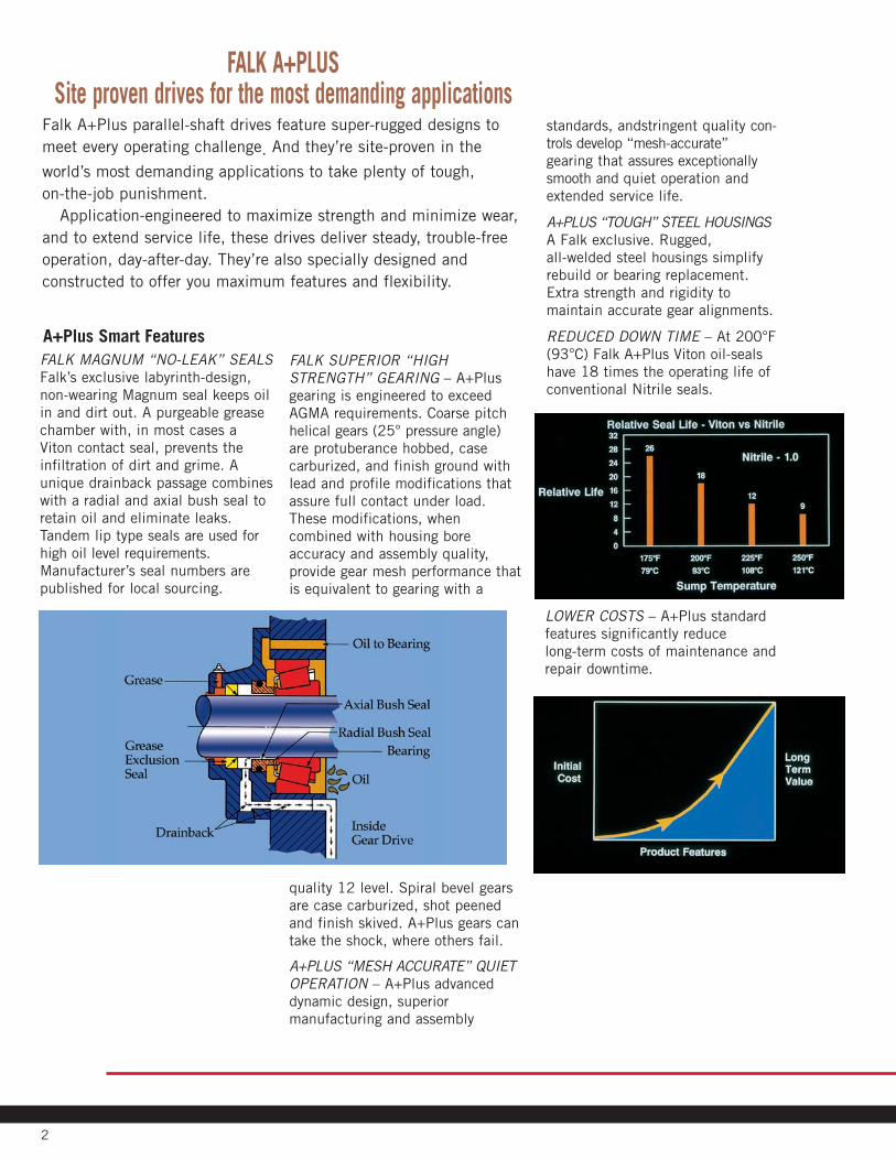
A+Plus Smart FeaturesFALK MAGNUM “NO-LEAK” SEALS
Falk’s exclusive labyrinth-design,
non-wearing Magnum seal keeps oil
in and dirt out. A purgeable grease
chamber with, in most cases a
Viton contact seal, prevents the
infiltration of dirt and grime. A
unique drainback passage combines
with a radial and axial bush seal to
retain oil and eliminate leaks.
Tandem lip type seals are used for
high oil level requirements.
Manufacturer’s seal numbers are
published for local sourcing.
FALK SUPERIOR “HIGH
STRENGTH” GEARING – A+Plus
gearing is engineered to exceed
AGMA requirements. Coarse pitch
helical gears (25° pressure angle)
are protuberance hobbed, case
carburized, and finish ground with
lead and profile modifications that
assure full contact under load.
These modifications, when
combined with housing bore
accuracy and assembly quality,
provide gear mesh performance that
is equivalent to gearing with a
quality 12 level. Spiral bevel gears
are case carburized, shot peened
and finish skived. A+Plus gears can
take the shock, where others fail.
A+PLUS “MESH ACCURATE” QUIET
OPERATION – A+Plus advanced
dynamic design, superior
manufacturing and assembly
standards, andstringent quality con-
trols develop “mesh-accurate”
gearing that assures exceptionally
smooth and quiet operation and
extended service life.
A+PLUS “TOUGH” STEEL HOUSINGS
A Falk exclusive. Rugged,
all-welded steel housings simplify
rebuild or bearing replacement.
Extra strength and rigidity to
maintain accurate gear alignments.
REDUCED DOWN TIME – At 200°F
(93°C) Falk A+Plus Viton oil-seals
have 18 times the operating life of
conventional Nitrile seals.
LOWER COSTS – A+Plus standard
features significantly reduce
long-term costs of maintenance and
repair downtime.
3
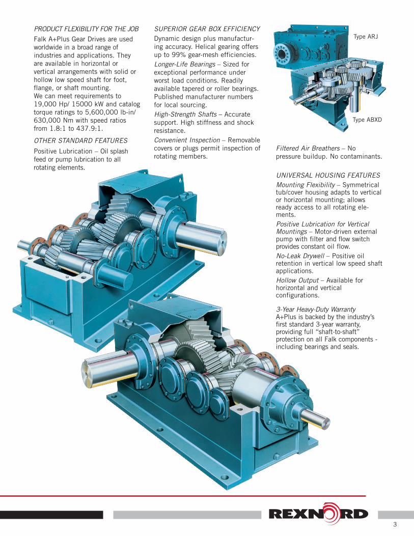
PRODUCT FLEXIBILITY FOR THE JOB
Falk A+Plus Gear Drives are used
worldwide in a broad range of
industries and applications. They
are available in horizontal or
vertical arrangements with solid or
hollow low speed shaft for foot,
flange, or shaft mounting.
We can meet requirements to
19,000 Hp/ 15000 kW and catalog
torque ratings to 5,600,000 lb-in/
630,000 Nm with speed ratios
from 1.8:1 to 437.9:1.
OTHER STANDARD FEATURES
Positive Lubrication – Oil splash
feed or pump lubrication to all
rotating elements.
SUPERIOR GEAR BOX EFFICIENCY
Dynamic design plus manufactur-
ing accuracy. Helical gearing offers
up to 99% gear-mesh efficiencies.
Longer-Life Bearings – Sized for
exceptional performance under
worst load conditions. Readily
available tapered or roller bearings.
Published manufacturer numbers
for local sourcing.
High-Strength Shafts – Accurate
support. High stiffness and shock
resistance.
Convenient Inspection – Removable
covers or plugs permit inspection of
rotating members.
Filtered Air Breathers – No
pressure buildup. No contaminants.
UNIVERSAL HOUSING FEATURES
Mounting Flexibility – Symmetricaltub/cover housing adapts to verticalor horizontal mounting; allowsready access to all rotating ele-ments.
Positive Lubrication for VerticalMountings – Motor-driven externalpump with filter and flow switchprovides constant oil flow.
No-Leak Drywell – Positive oilretention in vertical low speed shaftapplications.
Hollow Output – Available forhorizontal and vertical configurations.
3-Year Heavy-Duty WarrantyA+Plus is backed by the industry’sfirst standard 3-year warranty, providing full “shaft-to-shaft” protection on all Falk components -including bearings and seals.
Type ABXD
Type ARJ

4
AA++PPlluuss HHeeaavvyy--DDuuttyy DDrriivveess –– SSeelleeccttiioonn GGuuiiddee
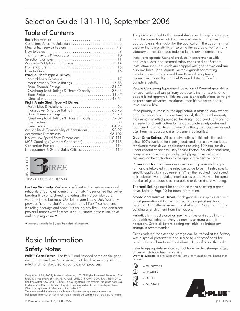
Table of ContentsBasic Information . . . . . . . . . . . . . . . . . . . . . . . . . . . . . . . . . 5Conditions Affecting Selection . . . . . . . . . . . . . . . . . . . . . . . . 6Mechanical Service Factors . . . . . . . . . . . . . . . . . . . . . . . . 7-8How to Select . . . . . . . . . . . . . . . . . . . . . . . . . . . . . . . . . . . . 9Thermal Factors & Procedures . . . . . . . . . . . . . . . . . . . . . . . 10Selection Examples . . . . . . . . . . . . . . . . . . . . . . . . . . . . . . . 11Accessory & Option Information . . . . . . . . . . . . . . . . . . . 12-14Nomenclature . . . . . . . . . . . . . . . . . . . . . . . . . . . . . . . . . . 15How to Order. . . . . . . . . . . . . . . . . . . . . . . . . . . . . . . . . . . 16Parallel Shaft Type A Drives
Assemblies & Rotations . . . . . . . . . . . . . . . . . . . . . . . . . . . 17Horsepower & Torque Ratings . . . . . . . . . . . . . . . . . . . 18-33Basic Thermal Ratings . . . . . . . . . . . . . . . . . . . . . . . . . 34-37Overhung Load Ratings & Thrust Capacity . . . . . . . . . . 38-45Exact Ratios . . . . . . . . . . . . . . . . . . . . . . . . . . . . . . . . 46-47Dimensions. . . . . . . . . . . . . . . . . . . . . . . . . . . . . . . . . 48-64
Right Angle Shaft Type AB DrivesAssemblies & Rotations . . . . . . . . . . . . . . . . . . . . . . . . . . . 65Horsepower & Torque Ratings . . . . . . . . . . . . . . . . . . . 66-75Basic Thermal Ratings . . . . . . . . . . . . . . . . . . . . . . . . . 76-78Overhung Load Ratings & Thrust Capacity . . . . . . . . . . 79-82Exact Ratios . . . . . . . . . . . . . . . . . . . . . . . . . . . . . . . . . . . 83Dimensions. . . . . . . . . . . . . . . . . . . . . . . . . . . . . . . . . 84-95
Availability & Compatibility of Accessories . . . . . . . . . . . . 96-97Accessories Dimensions . . . . . . . . . . . . . . . . . . . . . . . . 98-109Hollow Low Speed Shaft Dimensions. . . . . . . . . . . . . . 110-111MCF Couplings (Moment Connection) . . . . . . . . . . . . 112-113Conversion Factors . . . . . . . . . . . . . . . . . . . . . . . . . . . . . . 114Headquarters & Global Sales Offices. . . . . . . . . . . . . . . . . 116
Factory Warranty We’re so confident in the performance andreliability of our latest generation of Falk™ gear drives that we’rebacking this comprehensive offering with the best standardwarranty in the business. Our full, 3-year Heavy-Duty Warrantyprovides “shaft-to-shaft” protection on all Falk™ components –including bearings and seals. It’s an industry first... and one morepowerful reason why Rexnord is your ultimate bottom-line driveand coupling value.�
Safety NotesFalk™ Gear Drives The Falk™ and Rexnord name on the geardrive is the purchaser’s assurance that the drive was engineered,rated and manufactured to sound design practices.
The power supplied to the geared drive must be equal to or lessthan the power for which the drive was selected using theappropriate service factor for the application. The customer mustassume the responsibility of isolating the geared drive from anyvibratory or transient load induced by the driven equipment.
Install and operate Rexnord products in conformance withapplicable local and national safety codes and per Rexnordinstallation manuals which are shipped with gear drives and arealso available upon request. Suitable guards for rotatingmembers may be purchased from Rexnord as optionalaccessories. Consult your local Rexnord district office forcomplete details.
People Conveying Equipment Selection of Rexnord gear drivesfor applications whose primary purpose is the transportation ofpeople is not approved. This includes such applications as freightor passenger elevators, escalators, man lift platforms and skitows and ski lifts.
If the primary purpose of the application is material conveyanceand occasionally people are transported, the Rexnord warrantymay remain in effect provided the design load conditions are notexceeded and certification to the appropriate safety codes andload conditions has been obtained by the system designer or enduser from the appropriate enforcement authorities.
Gear Drive Ratings All gear drive ratings in this selection guideallow 100% overload for starting loads and momentary overloadsfor electric motor driven applications operating 10 hours per dayunder uniform conditions (unity Service Factor). For other conditions,compute an equivalent power by multiplying the actual powerrequired for the application by the appropriate Service Factor.
Power and Torque Gear drive mechanical power and torqueratings are tabulated in the selection guide to permit selections forspecific application requirements. When the required input speedfalls between two tabulated input speeds of a drive with the samenumber of gear reductions, interpolate to determine drive rating.
Thermal Ratings must be considered when selecting a geardrive. Refer to Page 10 for more information.
Stored and Inactive Drives Each gear drive is spin-tested witha rust preventive oil that will protect parts against rust for aperiod of 4 months in an outdoor shelter or 12 months in a drybuilding after shipment from the Factory.
Periodically inspect stored or inactive drives and spray internalparts with rust inhibitor every six months or more often, ifnecessary. Drain oil before adding rust inhibitor. Indoor drystorage is recommended.
Drives ordered for extended storage can be treated at the Factorywith a special preservative and sealed to rust-proof parts forperiods longer than those cited above, if specified on the order.
Refer to appropriate service manual for extended storage of geardrives which have been in service.Drawing Symbols The following symbols are used throughout the dimensioneddrawings.
© Rexnord Industries, LLC, 1998, 2006. (131-110) 5
Copyright 1998, 2003, Rexnord Industries, LLC. All Rights Reserved. Litho in U.S.A.FALK in a trademark of Rexnord. A-PLUS, LIFELIGN, OMNIBOX, RAM, REXNORD,RENEW, STEELFLEX, and ULTRAMITE are registered trademarks. Magnum Seal is atrademark of Rexnord for its rotary shaft sealing system for enclosed gear drives.Viton is a registered trademark of the DuPont Co.The contents of this selection guide are subject to change without notice orobligation. Information contained herein should be confirmed before placing orders.
®
= OIL DIPSTICK
= BREATHER
= OIL FILL
= OIL DRAIN
� Warranty extends for 3 years from date of shipment.
Selection Guide 131-110, September 2006
Basic Information
Non–Standard ApplicationProceduresThe following conditions may affect the gear drive selectionprocedure, drive size and auxiliary equipment being furnished.
Excessive Overloads The maximum momentary or starting loadmust not exceed 200% of rated load (100% overload). Ratedload is defined as gear drive rating with a Service Factor of 1.0.If the maximum starting or momentary load exceeds the aboveconditions, compute a second equivalent horsepower by dividingthe peak load by two. The gear drive selected must have capacityequal to, or in excess of, the larger equivalent horsepower.
Reversing Service Applications involving either more than 20reversals per 10 hour period, or less than 20 reversals per 10hour period with peak torques greater than 200% of normal loadmust be referred to the Factory.
Brake Equipped Applications When a gear drive is equippedwith a “working” brake that is used to decelerate the motion ofthe system and the brake is located between the prime moverand the gear drive, select the drive based on the brake rating orthe highest equivalent input power, whichever is greater. If thebrake is used for holding only and is applied after the motion ofthe system has come to rest, the brake rating must be less than200% of the catalog rating of the gear drive selected for theapplication. If the brake rating is greater than 200% of the geardrive catalog rating, refer the application to the Factory. Alsorefer to the Factory all applications in which the brake is locatedon the output shaft of the gear drive.
Oversize Prime Movers Published Service Factors do not coverapplications that require oversize prime movers for high energyor peak loads. Refer such applications to the Factory for selectionof suitable drives.
Speed Variation or Multi-Speed Applications — The geardrives offered in this selection guide (except Types AXV & ABX) aredesigned to operate with splash lubrication on any single speedapplication and any ratio shown in the selection guide unlessotherwise noted. It is essential that all orders indicate the desiredoperating speed and ratio so that the proper internal oildistribution accessories can be supplied for the specific speed.Types AXV and ABX use a separate motor driven oil pump toprovide lubrication.
These drives are assembled with a variety of standard internallubrication components such as oil pans and oil troughs toensure proper splash lubrication. In addition, different oil levelsare necessary for various drive sizes, speeds and ratios.Consequently, to operate an existing drive at different speedsfrom those shown on the nameplate, full application andnameplate information must be referred to the Factory for reviewof the lubrication system.
All variable or multi-speed applications will be referred to theEngineering Department to specify lubrication components foradequate lubrication at the slowest speed, without excessiveheating or churning at the highest speed. It is essential that allorders indicate minimum and maximum speeds, as well as thespeed duration cycles. A separate motor-driven oil pump (at anextra charge) may be required.
When selecting gear drives for multi-speed or variable speedapplications, determine the speed which develops the greatesttorque and select the drive on this basis. If the speed is not listedin the selection table, use the next lower speed.
Application Adjusted Thermal Rating, Page 10, TheApplication Adjusted Thermal Ratings is the actual power ratingwithout service factor that a gear drive will transmit continually forthree hours or more without overheating. The ApplicationAdjusted Thermal Rating considers the environmental factors ofthe application which will affect the ability of the drive to dissipateheat. These factors include ambient temperature, air velocity,altitude (thin air does not remove heat effectively), inlet watertemperature and duty cycle (percentage of an hour that the driveoperates). Factors for these conditions must be used to modifythe Basic Thermal Rating when determining the ApplicationAdjusted Thermal Rating.
Checking the thermal rating is extremely important. If a geardrive creates heat faster than it can be dissipated, severe damagemay occur.
If the gear drive operates for 3 hours or more per day and the runtime equals or exceeds the shutdown time, or if the continuousoperating time exceeds 3 hours, selection must be made on thebasis of adequate thermal rating using the Application AdjustedThermal Rating. The duty cycle factor considers an increase in theBasic Thermal Rating for gear drives that operate less than 100%of any one hour time period. If a drive operates for more thanthree hours and operates continuously for any given hour of theday, then the duty cycle must be considered 100%.
Effects of Solar Energy If a drive operates in the sun at ambienttemperatures over 100ºF (38ºC), then special measures must betaken to protect the drive from solar energy. This protection canconsist of a canopy over the drive or reflective paint on the drive.If neither is possible, a heat exchanger or other cooling devicemay be required.
Overhung Loads and Thrust Loads The overhung load and thrustload ratings published in this selection guide are based on a servicefactor of unity and a combination of the most unfavorable conditionsof rotation, speed, direction of applied load and drive loading. If thecalculated load exceeds the published value, or if an overhung loadand thrust load are applied simultaneously to a shaft, refer completeapplication details to Rexnord. For more information refer to tablesand guidelines on Pages 38-45 and 79-82.
Product Modifications Rexnord can supply special productmodifications to suit your application needs. Contact Rexnord forhousing modifications, special ratios, special shafts, specialmounting conditions, accessory modifications and other specialapplication requirements.
Seal Housing Grease All drives (and backstops if required) willbe shipped with NLGI #2 grease in the seal housing cavities.Where this grease could contaminate a product, such as in thefood and drug industries, clearly indicate on your purchase orderthat “Gear drive seal housing cavities must not contain grease.”
Oil Pump Equipped Application When a drive is equipped withan external motor driven oil pump, such as an AXV or ABX, andthe ambient temperature falls below 50 °F (10°C), or the oilviscosity is in excess of 8000 SSU, an oil heater may be requiredto maintain a satisfactory flow rate at startup to prevent bearingfailure. Refer to your local Rexnord district office.
6 (131-110) © Rexnord Industries, LLC, 1998, 2006.
Conditions Affecting Selection
© Rexnord Industries, LLC, 1998, 2006. (131-110) 7
Table 1 Service factor conversions
Table 2 or 33 to 10 Hour
ServiceFactor
3 to 10 Hoursper Day
Over 10 Hoursper Day
Intermittent–Up to3 Hours per Day †
Multi-Cyl.Engine ‡
Multi-Cyl.Engine ‡
MotorMulti-Cyl.Engine ‡
1.00 1.25 1.50 1.00 1.001.25 1.50 1.75 1.00 1.251.50 1.75 2.00 1.25 1.501.75 2.00 2.25 1.50 1.752.00 2.25 2.50 1.75 2.00
† For applications operating one half hour or less per day and applications drivenby single cylinder engines, refer to Factory.
‡ These service factors are based on the assumption that the system is free fromserious critical and torsional vibrations and that maximum momentary or startingloads do not exceed 200% of the normal load.
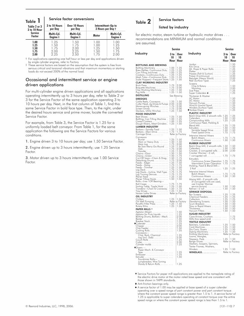
Occasional and intermittent service or enginedriven applications
For multi-cylinder engine driven applications and all applicationsoperating intermittently up to 3 hours per day, refer to Table 2 or3 for the Service Factor of the same application operating 3 to10 hours per day. Next, in the first column of Table 1, find thissame Service Factor in bold face type. Then, to the right, underthe desired hours service and prime mover, locate the convertedService Factor.
For example, from Table 3, the Service Factor is 1.25 for auniformly loaded belt conveyor. From Table 1, for the sameapplication the following are the Service Factors for variousconditions.
1. Engine driven 3 to 10 hours per day; use 1.50 Service Factor.
2. Engine driven up to 3 hours intermittently; use 1.25 ServiceFactor.
3. Motor driven up to 3 hours intermittently; use 1.00 ServiceFactor.
Service
Industry 3 to10
Hour
Over10
Hour
BOTTLING AND BREWINGBottling Machinery . . . . . . . . . 1.00 1.25Brew Kettles, Continuous Duty . 1.25 1.25Can Filling machines . . . . . . . 1.00 1.25Cookers—Continuous Duty . . . 1.25 1.25Mash Tubs—Continuous Duty . 1.25 1.25Scale Hoppers—Frequent Starts 1.25 1.50
CLAY WORKING INDUSTRYBrick Press . . . . . . . . . . . . . . . 1.75 2.00Briquette Machines . . . . . . . . . 1.75 2.00Clay Working Machinery . . . . . 1.25 1.50Pug Mills . . . . . . . . . . . . . . . . 1.25 1.50
DISTILLING See Brewing
DREDGESCable Reels, Conveyors . . . . . 1.25 1.50Cutter Head, Jig Drives & Pumps 2.00 2.00Maneuvering Winches. . . . . . . 1.75 2.00Screen Drives . . . . . . . . . . . . . 1.75 2.00Stackers, Utility Winches . . . . . 1.25 1.50
FOOD INDUSTRYBeet Slicers . . . . . . . . . . . . . . . 1.25 1.50Bottling, Can Filling Machine . 1.00 1.25Cereal Cookers . . . . . . . . . . . 1.00 1.25Dough Mixers, Meat Grinders . 1.25 1.50
LUMBER INDUSTRYBarkers—Spindle Feed . . . . . . 1.25 1.50Barkers—Main Drive . . . . . . . . 1.75 1.75Carriage Drive . . . . . . . . . Refer to Factory
ConveyorsBurner . . . . . . . . . . . . . . . . 1.25 1.50Main or Heavy Duty . . . . . . 1.50 1.50Main Log . . . . . . . . . . . . . . 1.75 2.00Re-Saw Merry-Go-Round . . 1.25 1.50Slab . . . . . . . . . . . . . . . . . . 1.75 2.00Transfer . . . . . . . . . . . . . . . 1.25 1.50
Chains—Floor . . . . . . . . . . . . 1.50 1.50Chains—Green . . . . . . . . . . . 1.50 1.75Cut-Off Saws—Chain & Drag . 1.50 1.75Debarking Drums . . . . . . . . . . 1.75 2.00Feeds—Edger . . . . . . . . . . . . . 1.25 1.50Feeds—Gang . . . . . . . . . . . . . 1.75 1.75Feeds—Trimmer . . . . . . . . . . . 1.25 1.50Log Deck . . . . . . . . . . . . . . . . 1.75 1.75Log Hauls—Incline, Well Type . 1.75 1.75Log Turning Devices . . . . . . . . 1.75 1.75Planer Feed . . . . . . . . . . . . . . 1.25 1.50Planer Tilting Hoists . . . . . . . . 1.50 1.50Rolls—Live—Off Bearing—Roll Cases . . . . . . . . . . . . . . . 1.75 1.75Sorting Table, Tipple Hoist . . . 1.25 1.50Transfers—Chain & Craneway. 1.50 1.75Tray Drives . . . . . . . . . . . . . . . 1.25 1.50Veneer Lathe Drives . . . . . . . . Refer to Factory
OIL INDUSTRYChillers. . . . . . . . . . . . . . . . . . 1.25 1.50Oil Well Pumping. . . . . . . Refer to FactoryParaffin Filter Press . . . . . . . . . 1.25 1.50Rotary Kilns. . . . . . . . . . . . . . . 1.25 1.50
PAPER MILLS �
Agitator (Mixer) . . . . . . . . . . . . . . . 1.50Agitator for Pure Liquids . . . . . . . . 1.25Barking Drums, Barkers—Mech. . . . 2.00Beater . . . . . . . . . . . . . . . . . . . . . 1.50Breaker Stack . . . . . . . . . . . . . . . . 1.25�Calender . . . . . . . . . . . . . . . . . . . 1.25
Chipper . . . . . . . . . . . . . . . . . . . . 2.00Chip Feeder . . . . . . . . . . . . . . . . . 1.50Coating Rolls . . . . . . . . . . . . . . . . 1.25Conveyors—
Chip, Bark, Chemical . . . . . . . . 1.25Log (incl. Slab) . . . . . . . . . . . . . 2.00
Couch Rolls . . . . . . . . . . . . . . . . . 1.25Cutter. . . . . . . . . . . . . . . . . . . . . . 2.00Cylinder molds . . . . . . . . . . . . . . . 1.25
�Dryers —Paper Mach. & ConveyorType . . . . . . . . . . . . . . . . . . . . . 1.25
Embosser . . . . . . . . . . . . . . . . . . . 1.25Extruder . . . . . . . . . . . . . . . . . . . . 1.50
Fourdrinier Rolls—Lumpbreaker, Wire TurningDandy & Return Rolls. . . . . . . . . 1.25
Service
Industry 3 to10
Hour
Over10
HourJordan . . . . . . . . . . . . . . . . . . . . . 1.50Kiln Drive . . . . . . . . . . . . . . . . . . . 1.50Mt. Hope & Paper Rolls . . . . . . . . . 1.25Platter. . . . . . . . . . . . . . . . . . . . . . 1.50Presses (Felt & Suction) . . . . . . . . . 1.25Pulper (Continuous) . . . . . . . . . . . 2.00Repulper (Heavy Shock). . . . . . . . . 2.00Reel (Surface Type) . . . . . . . . . . . . 1.25
ScreensChip & Rotary . . . . . . . . . . . . . . 1.50Vibrating. . . . . . . . . . . . . . . . . . 2.00
Size Press . . . . . . . . . . . . . . . . . . . 1.25Super Calenders � . . . . . . . . . . . . 1.25
Thickener & WasherAC Motor . . . . . . . . . . . . . . . . . . . 1.50DC Motor . . . . . . . . . . . . . . . . . . . 1.25Vacuum Pumps . . . . . . . . . . . . . . . 1.50Wind & Unwind Stand . . . . . . . . . . 1.25Winders (Surface Type) . . . . . . . . . 1.25�Yankee Dryers . . . . . . . . . . . . . . . 1.25
PLASTIC INDUSTRYBatch Drop Mill, 2 smooth rolls 1.25 1.25Calenders. . . . . . . . . . . . . . . . 1.50 1.50Compounding Mills . . . . . . . . 1.25 1.25Continuous Feed, Holding &Blend Mill . . . . . . . . . . . . . . . . 1.25 1.25Extruders . . . . . . . . . . . . . . . . 1.50 1.50
Variable Speed Drive. . . . . . 1.50 1.50Fixed Speed Drive . . . . . . . . 1.75 1.75
Intensive Internal MixersBatch Mixers . . . . . . . . . . . . 1.75 1.75Continuous Mixers . . . . . . . 1.50 1.50
RUBBER INDUSTRYBatch Drop Mill, 2 smooth rolls 1.50 1.50Calenders. . . . . . . . . . . . . . . . 1.50 1.50Cracker, 2 corrugated rolls . . . 2.00 2.00Cracker Warmer—2 roll,1 corrugated roll. . . . . . . . . . . 1.75 1.75
ExtrudersContinuous Screw Operation 1.75 1.75Intermittent Screw Operation 1.75 1.75
Holding, Feed & Blend Mill—2 Roll . . . . . . . . . . . . . . . . . . 1.25 1.25
Intensive Internal MixersBatch Mixers . . . . . . . . . . . . 1.75 1.75Continuous Mixers . . . . . . . 1.50 1.50
Mixing Mill—2 smooth rolls(if corrugated rolls are used,use Cracker Warmerservice factors) . . . . . . . . . . 1.50 1.50
Refiner—2 roll . . . . . . . . . . . . 1.50 1.50
SEWAGE DISPOSALBar Screens . . . . . . . . . . . . . . 1.25 1.25Chemical Feeders . . . . . . . . . . 1.25 1.25Collectors . . . . . . . . . . . . . . . . 1.25 1.25Dewatering Screens. . . . . . . . . 1.50 1.50Scum Breakers . . . . . . . . . . . . 1.50 1.50Slow or Rapid Mixers. . . . . . . . 1.50 1.50Thickeners . . . . . . . . . . . . . . . 1.50 1.50Vacuum Filters . . . . . . . . . . . . 1.50 1.50
SUGAR INDUSTRYCane Knives, Crushers . . . . . . . . . 1.75Mills (low speed end) . . . . . . . . . . 1.75
TEXTILE INDUSTRYBatchers, Calenders . . . . . . . . 1.25 1.50Card Machines . . . . . . . . . . . . 1.25 1.50Dry Cans, Dryers. . . . . . . . . . . 1.25 1.50Dyeing Machinery . . . . . . . . . . 1.25 1.50Knitting Machinery . . . . . . Refer to FactoryLooms, Mangles,Nappers, Pads . . . . . . . . . . . . 1.25 1.50Range Drives . . . . . . . . . . Refer to FactorySlashers, Soapers, Spinners,Tenter Frames, Washers,Winders . . . . . . . . . . . . . . . . . 1.25 1.50
WINDLASS . . . . . . . . . . Refer to Factory
Table 2 Service factors
listed by industry
for electric motor, steam turbine or hydraulic motor drives . . .recommendations are MINIMUM and normal conditionsare assumed.
� Service Factors for paper mill applications are applied to the nameplate rating ofthe electric drive motor at the motor rated base speed and are consistent withthose shown in TAPPI standards.
� Anti-friction bearings only.
� A service factor of 1.00 may be applied at base speed of a super calenderoperating over a speed range of part constant power and part constant torquewhere the constant power speed range is greater than 1.5 to 1. A service factor of1.25 is applicable to super calenders operating at constant torque over the entirespeed range or where the constant power speed range is less than 1.5 to 1.
8 (131-110) © Rexnord Industries, LLC, 1998, 2006.
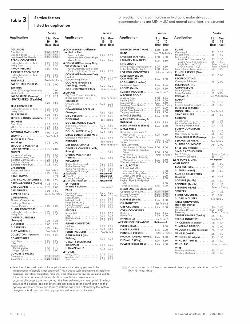
Table 3 Service factors
listed by application
for electric motor, steam turbine or hydraulic motor drives . . .recommendations are MINIMUM and normal conditions are assumed
Service
Application 3 to10
Hour
Over10
Hour
AGITATORSPure Liquids . . . . . . . . . . . . . . 1.00 1.25Liquids & Solids . . . . . . . . . . . 1.25 1.50Liquids-Variable Density . . . . . 1.25 1.50
APRON CONVEYORSUniformly Loaded or Fed. . . . . 1.25 1.50Heavy Duty . . . . . . . . . . . . . . . 1.25 1.50
APRON FEEDERS 1.25 1.50
ASSEMBLY CONVEYORSUniformly Loaded or Fed. . . . . 1.25 1.25Heavy Duty . . . . . . . . . . . . . . . 1.25 1.50
BALL MILLS . . . . . . . . . . See Mills, Rotary
BARGE HAUL PULLERS . . . . 1.75 2.00
BARKINGDrums (Coupling Connected) . . . . 2.00Mechanical. . . . . . . . . . . . . . . . . . 2.00
BAR SCREENS (Sewage) 1.25 1.25
BATCHERS (Textile)1.25 1.50
BELT CONVEYORSUniformly Loaded or Fed. . . . . 1.25 1.25Heavy Duty . . . . . . . . . . . . . . . 1.25 1.50
BELT FEEDERS 1.25 1.50
BENDING ROLLS (Machine) 1.25 1.50
BLOWERSCentrifugal . . . . . . . . . . . . . . . 1.25 1.25Lobe. . . . . . . . . . . . . . . . . . . . 1.25 1.50Vane . . . . . . . . . . . . . . . . . . . 1.25 1.50
BOTTLING MACHINERY . . . 1.00 1.25
BREWING . . . . . . . . . . . . . . . See Table 2
BRICK PRESS (ClayWorking) . . . . . . . . . . . . . . . 1.75 2.00
BRIQUETTE MACHINES(Clay Working) . . . . . . . . . . 1.75 2.00
BUCKETConveyors Uniform . . . . . . . . . 1.25 1.50Conveyors Heavy Duty . . . . . . 1.25 1.50Elevators Continuous . . . . . . . 1.25 1.50Elevators Uniform . . . . . . . . . . 1.25 1.50Elevators Heavy Duty. . . . . . . . 1.25 1.50
CALENDERSRubber and Plastic . . . . . . . . . See Table 2Textile. . . . . . . . . . . . . . . . . . . 1.25 1.50
CANE KNIVES . . . . . . . . . . . . . . 1.75
CAN FILLING MACHINES . . 1.00 1.25
CARD MACHINES (Textile) . 1.25 1.50
CAR DUMPERS . . . . . . . . . . . 1.75 2.00
CAR PULLERS . . . . . . . . . . . . 1.25 1.50
CEMENT KILNS . . . . . . . See Mills, Rotary
CENTRIFUGALBlowers, Compressors,Discharge Elevators,Fans or Pumps . . . . . . . . . . . . 1.25 1.25
CHAIN CONVEYORSUniformly Loaded or Fed. . . . . 1.25 1.25Heavy Duty . . . . . . . . . . . . . . . 1.25 1.50
CHEMICAL FEEDERS(Sewage) . . . . . . . . . . . . . . . 1.25 1.25
CLARIFIERS. . . . . . . . . . . . . . 1.00 1.25
CLASSIFIERS. . . . . . . . . . . . . 1.25 1.50
CLAY WORKING . . . . . . . . . See Table 2
COLLECTORS (Sewage) 1.25 1.25
COMPRESSORSCentrifugal . . . . . . . . . . . . . . . 1.25 1.25Lobe. . . . . . . . . . . . . . . . . . . . 1.25 1.50Reciprocating
Multi-Cylinder . . . . . . . . . . . 1.50 1.75Single-Cylinder . . . . . . . . . . 1.75 2.00
CONCRETE MIXERSContinuous. . . . . . . . . . . . . . . 1.25 1.50Intermittent . . . . . . . . . . . . . . . 1.25 1.50
Service
Application 3 to10
Hour
Over10
Hour
�CONVEYORS—Uniformlyloaded or Fed:
Apron or Bucket . . . . . . . . . . 1.25 1.50Assembly, Belt, Chain, Flight,Oven, Screw . . . . . . . . . . . . 1.25 1.25
�CONVEYORS—Heavy Duty,Not Uniformly Fed
Apron, Assembly, Belt, Bucket,Chain, Flight, Oven, Screw . . 1.25 1.50
CONVEYORS—Severe DutyLive Roll . . . . . . . . . . . . . . Refer to FactoryReciprocating Shaker . . . . . . . 1.75 2.00
COOKERS (Brewing &Distilling), (food) . . . . . . . . . 1.25 1.25
COOLING TOWER FANS Refer to Factory
�CRANESDry Dock Cranes, Main Hoist,Bridge and Trolley Travel . Refer to Factory
CRUSHERSOre or Stone . . . . . . . . . . . . . 1.75 2.00Sugar . . . . . . . . . . . . . . . . . . . . . . 1.75
DEWATERING SCREENS(Sewage) . . . . . . . . . . . . . . . 1.50 1.50
DISC FEEDERS . . . . . . . . . . . 1.00 1.25
DISTILLING. . . . . . . . . . . . . . See Table 2
DOUBLE ACTING PUMPS2 or more Cylinders . . . . . . . . 1.25 1.50Single Cylinder . . . . . . . . . . . . Refer to Factory
DOUGH MIXER (Food) . . . . 1.25 1.50
DRAW BENCH (Metal Mills)Carriage & Main Drive . . . . . . 1.25 1.50
DREDGES . . . . . . . . . . . . . . . See Table 2
DRY DOCK CRANES . . . Refer to Factory
DRYERS & COOLERS (Mills,Rotary) . . . . . . . . . . . . . . . . . . . . 1.50
DYEING MACHINERY(Textile) . . . . . . . . . . . . . . . . . 1.25 1.50
ELEVATORSBucket-Uniform Lood . . . . . . . 1.25 1.50Bucket-Heavy Duty . . . . . . . . . 1.25 1.50Bucket-Continuous . . . . . . . . . 1.25 1.50Centrifugal Discharge . . . . . . . 1.25 1.25
�Escalators . . . . . . . . . . . . . . . Not Approved�Freight . . . . . . . . . . . . . . . . . . Not Approved
Gravity Discharge . . . . . . . . . . 1.00 1.25�Man Lifts, Passenger . . . . . . . . Not Approved
EXTRUDERS(Plastic & Rubber) . . . . . . . . See Table 2
FANSCentrifugal . . . . . . . . . . . . . . . 1.25 1.25Cooling Towers . . . . . . . . . . . Refer to FactoryForced Draft . . . . . . . . . . . . . . . . . 1.25Induced Draft . . . . . . . . . . . . . 1.50 1.50Large (Mine, etc.) . . . . . . . . . . 1.50 1.50Large lndustrial . . . . . . . . . . . . 1.50 1.50Light (Small Diameter) . . . . . . . 1.00 1.25
FEEDERSApron, Belt . . . . . . . . . . . . . . . 1.25 1.50Disc . . . . . . . . . . . . . . . . . . . . 1.00 1.25Reciprocating . . . . . . . . . . . . . 1.75 2.00Screw . . . . . . . . . . . . . . . . . . . 1.25 1.50
FLIGHT CONVEYORSUniform . . . . . . . . . . . . . . . . . 1.25 1.25Heavy. . . . . . . . . . . . . . . . . . . 1.25 1.50
FOOD INDUSTRY . . . . . . . . See Table 2
GENERATORS (NotWelding). . . . . . . . . . . . . . . . 1.00 1.25
GRAVITY DISCHARGEELEVATORS . . . . . . . . . . . . . 1.00 1.25
HAMMER MILLS . . . . . . . . . . 1.75 2.00
�HOISTSHeavy Duty . . . . . . . . . . . . . . . 1.75 2.00Medium Duty . . . . . . . . . . . . . 1.25 1.50Skip Hoist . . . . . . . . . . . . . . . . 1.25 1.50
Service
Application 3 to10
Hour
Over10
Hour
INDUCED DRAFT FANS . . . 1.50 1.50
KILNS . . . . . . . . . . . . . . . See Mills, Rotary
LAUNDRY WASHERS . . . . . . 1.50 2.00
LAUNDRY TUMBLERS . . . . . 1.25 1.50
LINE SHAFTSDriving Processing Equipment . 1.25 1.50Other Line Shafts, Light . . . . . . 1.00 1.25
LIVE ROLL CONVEYORS Refer to Factory
LOBE BLOWERS ORCOMPRESSORS . . . . . . . . . . 1.25 1.50
LOG HAULS (Lumber)Incline-well Type . . . . . . . . . . . 1.75 1.75
LOOMS (Textile) . . . . . . . . . . 1.25 1.50
LUMBER INDUSTRY . . . . . . . See Table 2
MACHINE TOOLSAuxiliary Drives . . . . . . . . . . . . 1.00 1.25Bending Rolls . . . . . . . . . . . . . 1.25 1.50Main Drives . . . . . . . . . . . . . . 1.25 1.50Notching Press (Belted) . . . . . . Refer to FactoryPlate Planers . . . . . . . . . . . . . . 1.75 2.00Punch Press (Geared) . . . . . . . 1.75 2.00Tapping machines. . . . . . . . . . 1.75 2.00
MANGLE (Textile). . . . . . . . . 1.25 1.50
MASH TUBS (Brewing &Distilling) . . . . . . . . . . . . . . . 1.25 1.25
MEAT GRINDERS (Food) . . . 1.25 1.50
METAL MILLSDraw Bench Carriages &
Main Drives . . . . . . . . . . . . 1.25 1.50Pinch, Dryer & Scrubber
Rolls, Reversing . . . . . . . . . . Refer to FactorySlitters . . . . . . . . . . . . . . . . . . 1.25 1.50Table Conveyors,
Non-Reversing Group Drives 1.50 1.50Non-Reversing IndividualDrives . . . . . . . . . . . . . . . . . 2.00 2.00Reversing . . . . . . . . . . . . . . Refer to Factory
Wire Drawing & FlatteningMachines . . . . . . . . . . . . . . 1.25 1.50
Wire Winding Machines . . . . . 1.50 1.50
MILLS, ROTARYBall and Rod Mills
with Spur Ring Gear . . . . . . . . . 2.00with Helical Ring Gear . . . . . . . 1.50Direct Connected . . . . . . . . . . . 2.00
Cement Kilns, Dryers & Coolers . . . 1.50Pebble, Plain & Wedge Bar
Mills . . . . . . . . . . . . . . . . . . . . . 1.50Tumbling Barrels. . . . . . . . . . . 1.75 2.00
MIXER (Also see Agitators)Concrete, Cont. & lnt.. . . . . . . 1.25 1.50Constant Density. . . . . . . . . . . 1.25 1.50Variable Density . . . . . . . . . . . 1.25 1.50
NAPPERS (Textile) . . . . . . . . 1.25 1.50
OIL INDUSTRY . . . . . . . . . . . See Table 2
ORE CRUSHERS . . . . . . . . . . 1.75 2.00
OVEN CONVEYORSUniform . . . . . . . . . . . . . . . . . 1.25 1.25Heavy Duty . . . . . . . . . . . . . . . 1.25 1.50
PAPER MILLS. . . . . . . . . . . . . See Table 2
�PASSENGER ELEVATORS Not Approved
PEBBLE MILLS . . . . . . . . . . . . . . . 1.50
PLATE PLANERS . . . . . . . . . . 1.75 2.00
PRINTING PRESSES. . . . Refer to Factory
PROPORTIONING PUMPS. . 1.25 1.50
PUG MILLS (Clay) . . . . . . . . 1.25 1.50
PULLERS (Barge Haul). . . . . 1.75 2.00
Service
Application 3 to10
Hour
Over10
Hour
PUMPSCentrifugal . . . . . . . . . . . . . . . 1.25 1.25Proportioning . . . . . . . . . . . . . 1.25 1.50Reciprocating
Single Act., 3 or more Cyl. . 1.25 1.50Double Act., 2 or more Cyl. 1.25 1.50Single Act., 1 or 2 Cyl. . . . . Refer to FactoryDouble Acting, 1 Cyl. . . . . . Refer to Factory
Rotary: Gear, Lobe, Vane . . . . 1.00 1.25
PUNCH PRESSES (GearDriven) . . . . . . . . . . . . . . . . . 1.75 2.00
RECIPROCATINGConveyors & Feeders . . . . . . . 1.75 2.00
RECIPROCATINGCOMPRESSORSMultI-Cylinder. . . . . . . . . . . . . 1.50 1.75Single Cylinder . . . . . . . . . . . . 1.75 2.00
ROD MILLS . . . . . . . . . . See Mills, Rotary
ROTARYPumps . . . . . . . . . . . . . . . . . . 1.00 1.25Screens (Sand or Gravel). . . . . 1.25 1.50
RUBBER & PLASTICSINDUSTRIES . . . . . . . . . . . . . See Table 2
SAND MULLERS . . . . . . . . . . 1.25 1.50
SCREENSAir Washing . . . . . . . . . . . . . . 1.00 1.25Rotary—Sand or Gravel . . . . . 1.25 1.50Traveling Water Intake . . . . . . 1.00 1.25
SCREW CONVEYORSUniform . . . . . . . . . . . . . . . . . 1.25 1.25Heavy Duty or Feeder . . . . . . . 1.25 1.50
SCUM BREAKERS (Sewage) 1.50 1.50
SEWAGE DISPOSAL . . . . . . . See Table 2
SHAKER CONVEYORS . . . . . 1.75 2.00
SHEETERS (Rubber) . . . . . . . . . . 1.50
SINGLE ACTING PUMPI or 2 Cylinders . . . . . . . . Refer to Factory3 or more Cylinders . . . . . . . . 1.25 1.50
�SKI TOWS & LIFTS Not Approved
�SKIP HOIST 1.25 1.50
SLAB PUSHERS . . . . . . . . . . . 1.50 1.50
SLITTERS (Metal) . . . . . . . . . 1.25 1.50
SLUDGE COLLECTORS(Sewage) . . . . . . . . . . . . . . . 1.25 1.25
SOAPERS (Textile) . . . . . . . . 1.25 1.50
SPINNERS (Textile). . . . . . . . 1.25 1.50
STEERING GEARS . . . . . Refer to Factory
STOKERS. . . . . . . . . . . . . . . . 1.00 1.25
STONE CRUSHERS. . . . . . . . 1.75 2.00
SUGAR INDUSTRY . . . . . . . . See Table 2
TABLE CONVEYORS(Non-Reversing)Group Drives . . . . . . . . . . . . . 1.50 1.50Individual Drives . . . . . . . . . . . 2.00 2.00Reversing . . . . . . . . . . . . . Refer to Factory
TENTER FRAMES (Textile) . . 1.25 1.50
TEXTILE INDUSTRY . . . . . . . See Table 2
THICKENERS (Sewage) . . . . 1.50 1.50
TUMBLING BARRELS . . . . . . 1.75 2.00
VACUUM FILTERS (Sewage) 1.50 1.50
VANE BLOWERS . . . . . . . . . 1.25 1.50
WINCHES (Dredges) . . . . . . 1.25 1.50
WINDERS (Textile) . . . . . . . . 1.25 1.50
WINDLASS . . . . . . . . . . . . . . Refer to Factory
WIREDrawing Machines . . . . . . . . . 1.25 1.50Winding Machines . . . . . . . . . 1.50 1.50
� Selection of Rexnord products for applications whose primary purpose is thetransportation of people is not approved. This includes such applications as freight orpassenger elevators, escalators, man lifts, work lift platforms and ski tows and ski lifts.If the primary purpose of the application is material conveyance andoccasionally people are transported, the Rexnord warranty may remain in effectprovided the design load conditions are not exceeded and certification to theappropriate safety codes and load conditions has been obtained by the systemdesigner or end user from the appropriate enforcement authorities.
Contact your local Rexnord representative for proper selection of a Falk™RAM ® mixer drive.
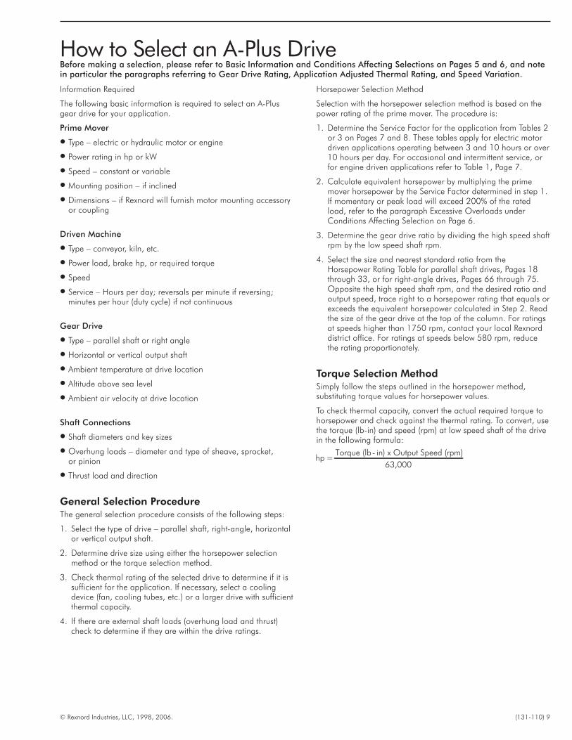
Information Required
The following basic information is required to select an A-Plusgear drive for your application.
Prime Mover
� Type – electric or hydraulic motor or engine
� Power rating in hp or kW
� Speed – constant or variable
� Mounting position – if inclined
� Dimensions – if Rexnord will furnish motor mounting accessoryor coupling
Driven Machine
� Type – conveyor, kiln, etc.
� Power load, brake hp, or required torque
� Speed
� Service – Hours per day; reversals per minute if reversing;minutes per hour (duty cycle) if not continuous
Gear Drive
� Type – parallel shaft or right angle
� Horizontal or vertical output shaft
� Ambient temperature at drive location
� Altitude above sea level
� Ambient air velocity at drive location
Shaft Connections
� Shaft diameters and key sizes
� Overhung loads – diameter and type of sheave, sprocket,or pinion
� Thrust load and direction
General Selection ProcedureThe general selection procedure consists of the following steps:
1. Select the type of drive – parallel shaft, right-angle, horizontalor vertical output shaft.
2. Determine drive size using either the horsepower selectionmethod or the torque selection method.
3. Check thermal rating of the selected drive to determine if it issufficient for the application. If necessary, select a coolingdevice (fan, cooling tubes, etc.) or a larger drive with sufficientthermal capacity.
4. If there are external shaft loads (overhung load and thrust)check to determine if they are within the drive ratings.
Horsepower Selection Method
Selection with the horsepower selection method is based on thepower rating of the prime mover. The procedure is:
1. Determine the Service Factor for the application from Tables 2or 3 on Pages 7 and 8. These tables apply for electric motordriven applications operating between 3 and 10 hours or over10 hours per day. For occasional and intermittent service, orfor engine driven applications refer to Table 1, Page 7.
2. Calculate equivalent horsepower by multiplying the primemover horsepower by the Service Factor determined in step 1.If momentary or peak load will exceed 200% of the ratedload, refer to the paragraph Excessive Overloads underConditions Affecting Selection on Page 6.
3. Determine the gear drive ratio by dividing the high speed shaftrpm by the low speed shaft rpm.
4. Select the size and nearest standard ratio from theHorsepower Rating Table for parallel shaft drives, Pages 18through 33, or for right-angle drives, Pages 66 through 75.Opposite the high speed shaft rpm, and the desired ratio andoutput speed, trace right to a horsepower rating that equals orexceeds the equivalent horsepower calculated in Step 2. Readthe size of the gear drive at the top of the column. For ratingsat speeds higher than 1750 rpm, contact your local Rexnorddistrict office. For ratings at speeds below 580 rpm, reducethe rating proportionately.
Torque Selection MethodSimply follow the steps outlined in the horsepower method,substituting torque values for horsepower values.
To check thermal capacity, convert the actual required torque tohorsepower and check against the thermal rating. To convert, usethe torque (lb-in) and speed (rpm) at low speed shaft of the drivein the following formula:
hp =Torque (lb - in) x Output Speed (rpm)
63,000
© Rexnord Industries, LLC, 1998, 2006. (131-110) 9
How to Select an A-Plus DriveBefore making a selection, please refer to Basic Information and Conditions Affecting Selections on Pages 5 and 6, and notein particular the paragraphs referring to Gear Drive Rating, Application Adjusted Thermal Rating, and Speed Variation.
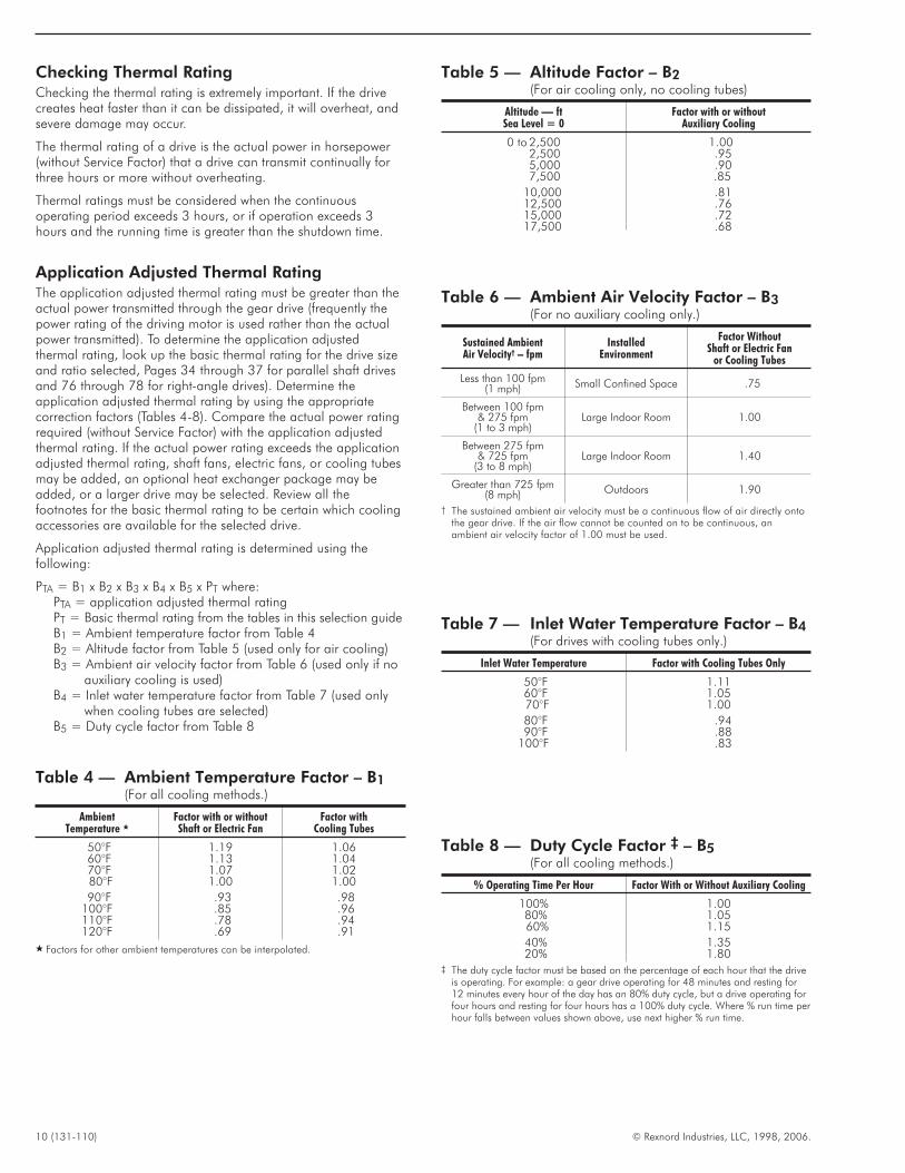
Checking Thermal RatingChecking the thermal rating is extremely important. If the drivecreates heat faster than it can be dissipated, it will overheat, andsevere damage may occur.
The thermal rating of a drive is the actual power in horsepower(without Service Factor) that a drive can transmit continually forthree hours or more without overheating.
Thermal ratings must be considered when the continuousoperating period exceeds 3 hours, or if operation exceeds 3hours and the running time is greater than the shutdown time.
Application Adjusted Thermal RatingThe application adjusted thermal rating must be greater than theactual power transmitted through the gear drive (frequently thepower rating of the driving motor is used rather than the actualpower transmitted). To determine the application adjustedthermal rating, look up the basic thermal rating for the drive sizeand ratio selected, Pages 34 through 37 for parallel shaft drivesand 76 through 78 for right-angle drives). Determine theapplication adjusted thermal rating by using the appropriatecorrection factors (Tables 4-8). Compare the actual power ratingrequired (without Service Factor) with the application adjustedthermal rating. If the actual power rating exceeds the applicationadjusted thermal rating, shaft fans, electric fans, or cooling tubesmay be added, an optional heat exchanger package may beadded, or a larger drive may be selected. Review all thefootnotes for the basic thermal rating to be certain which coolingaccessories are available for the selected drive.
Application adjusted thermal rating is determined using thefollowing:
PTA = B1 x B2 x B3 x B4 x B5 x PT where:PTA = application adjusted thermal ratingPT = Basic thermal rating from the tables in this selection guideB1 = Ambient temperature factor from Table 4B2 = Altitude factor from Table 5 (used only for air cooling)B3 = Ambient air velocity factor from Table 6 (used only if no
auxiliary cooling is used)B4 = Inlet water temperature factor from Table 7 (used only
when cooling tubes are selected)B5 = Duty cycle factor from Table 8
10 (131-110) © Rexnord Industries, LLC, 1998, 2006.
Table 4 — Ambient Temperature Factor – B1(For all cooling methods.)
AmbientTemperature �
Factor with or withoutShaft or Electric Fan
Factor withCooling Tubes
50°F 1.19 1.0660°F 1.13 1.0470°F 1.07 1.0280°F 1.00 1.00
90°F .93 .98100°F .85 .96110°F .78 .94120°F .69 .91
� Factors for other ambient temperatures can be interpolated.
Table 5 — Altitude Factor – B2(For air cooling only, no cooling tubes)
Altitude — ftSea Level = 0
Factor with or withoutAuxiliary Cooling
0 to 2,500 1.002,500 .955,000 .907,500 .85
10,000 .8112,500 .7615,000 .7217,500 .68
Table 6 — Ambient Air Velocity Factor – B3(For no auxiliary cooling only.)
Sustained AmbientAir Velocity† – fpm
InstalledEnvironment
Factor WithoutShaft or Electric Fan
or Cooling Tubes
Less than 100 fpm(1 mph) Small Confined Space .75
Between 100 fpm& 275 fpm
(1 to 3 mph)Large Indoor Room 1.00
Between 275 fpm& 725 fpm
(3 to 8 mph)Large Indoor Room 1.40
Greater than 725 fpm(8 mph) Outdoors 1.90
† The sustained ambient air velocity must be a continuous flow of air directly ontothe gear drive. If the air flow cannot be counted on to be continuous, anambient air velocity factor of 1.00 must be used.
Table 7 — Inlet Water Temperature Factor – B4(For drives with cooling tubes only.)
Inlet Water Temperature Factor with Cooling Tubes Only
50°F 1.1160°F 1.0570°F 1.00
80°F .9490°F .88
100°F .83
Table 8 — Duty Cycle Factor ‡ – B5(For all cooling methods.)
% Operating Time Per Hour Factor With or Without Auxiliary Cooling
100% 1.0080% 1.0560% 1.15
40% 1.3520% 1.80
‡ The duty cycle factor must be based on the percentage of each hour that the driveis operating. For example: a gear drive operating for 48 minutes and resting for12 minutes every hour of the day has an 80% duty cycle, but a drive operating forfour hours and resting for four hours has a 100% duty cycle. Where % run time perhour falls between values shown above, use next higher % run time.
Shaft RatingsHigh speed and low speed shaft ratings should be checked if theapplication involves an applied bending moment, for example asheave, sprocket, pinion, or some type of rigid coupling on eithershaft. In addition, drives with vertical low speed shafts should bechecked to determine if any thrust that could be applied to theshaft is within the limits of the shaft.
Shaft ratings for parallel shaft drives are found on Pages 38through 45. Right-angle drive shaft ratings are found on Pages79 through 82. Instructions for using these ratings are also foundon these pages.
Horsepower Selection ExampleA draw bench requiring 135 brake hp operates 10 hours per dayat 30 rpm, and is driven by a 150 hp, 1170 rpm electric motor.Ambient temperature at the draw bench never exceeds 90°F. Thedraw bench is located in a large indoor room, but air flow in thearea is only 200 fpm. The high speed and low speed shafts willbe connected to the drive and driven equipment with flexibleshaft couplings. Select a parallel shaft gear drive for thisapplication.
1. The Service Factor is 1.25 for a draw bench drive operating10 hours per day from Page 8, Table 3.
2. The equivalent hp = 1.25 x 135 = 169 hp.
3. The required ratio is 1170 30 = 39. The closest standard ratiois 38.44 from the Triple Reduction Selection Table on Page 26.
4. Using the Triple Reduction Selection Table on Page 26, in the1170 rpm high speed shaft section opposite the 38.44:1 ratioand 30 rpm, trace right to 181 (nearest hp exceeding theequivalent hp of 169) and read the drive size 425 at the topof the column.
5. The basic thermal capacity for a 425A3, 38.44:1, at 1170 rpmwith no auxiliary cooling from the Basic Thermal Rating Tableon Page 36 is 120 hp.
6. The ambient temperature factor (B1) is 0.93 from Table 4, andthe altitude factor (B2) and ambient air velocity factor (B3) are1.0 from Tables 5 and 6. The duty cycle factor (B5) is 1.0 fromTable 8.
7. The application adjusted thermal capacity is 120 x .93 x 1 x 1x 1 = 111.6 hp. This is not adequate because the actualbrake hp is 135 hp.
8. The basic thermal capacity for a 425A3, 38.44:1 with twoshaft fans is 170 hp. This is adequate since 158.1 (170 x .93x 1 x 1) is greater than the 135 hp required. Note that theambient air factor (B3) is no longer used the in the calculationof application adjusted thermal capacity because the drive isnow fan cooled.
9. Shaft ratings do not need to be checked because the driveis connected by flexible couplings at both the high speedand low speed shafts. Refer to Factory coupling selectionguides for coupling selections.
Torque Selection ExampleA dredge requires 190,000 lb-in. torque at its output shaft, andoperates at 13 rpm. The winch is in service 10 hours per day andis driven by a flexible coupling-connected 50 hp, 1170 rpmelectric motor. The ambient temperature never exceeds 100°F.Although the dredge operates outdoors, the average sustainedwind velocity is only 5 mph. The dredge operates on the GreatLakes which can be considered to be near sea level. The winchnever operates more than 45 minutes in any given hour. Thespace available is best suited to a right-angle gear drive. Select agear drive for this application.
1. The Service Factor is 1.25 for a dredge winch drive operating10 hours per day from Page 8, Table 3 under Winches(Dredges).
2. The equivalent torque is 1.25 x 190,000 = 237,500 lb-in.
3. The required ratio is 1170 13 = 90. The closest standard ratiois 86.5 from the quadruple reduction selection table on Page 73.
4. Using the Quadruple Reduction Table on Page 73, in the1170 rpm high speed shaft section opposite 85.60:1 ratioand 13.5 rpm, trace right to 253 ( x 1000, nearest torqueexceeding the equivalent torque of 237,500 lb-in) and readthe drive size 405 at the top of the column.
5. The basic thermal capacity with no auxiliary cooling for a405, 86.50:1 at 1170 rpm from the table on Page 78 is 56.2hp. The ambient temperature factor (B1) from Table 4, Page10, is .85. The altitude correction factor (B2) is 1.0 fromTable 5, Page 10. The ambient air velocity factor (B3) is 1.4from Table 6, Page 10. The duty cycle is 75% (45 min/60min), so the duty cycle factor is 1.05 from Table 8, Page 10.
6. The application adjusted thermal capacity is 56.2 x 0.85 x 1.0x 1.4 x 1.05 = 70.2 hp which exceeds the hp rating of themotor (50 hp). Therefore, no additional cooling is required.
7. Shaft ratings do not need to be checked because the driveis connected by flexible couplings at both the high speedand low speed shafts. Refer to Rexnord coupling selectionguides for coupling selections.
© Rexnord Industries, LLC, 1998, 2006. (131-110) 11
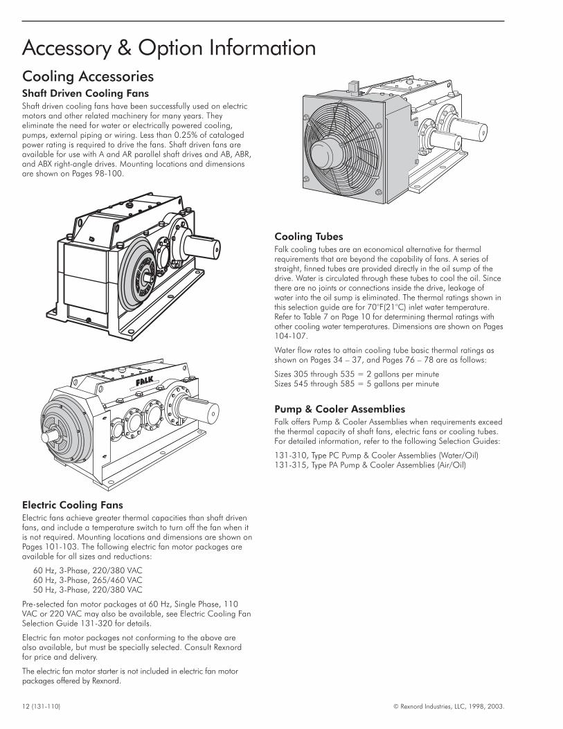
Cooling AccessoriesShaft Driven Cooling FansShaft driven cooling fans have been successfully used on electricmotors and other related machinery for many years. Theyeliminate the need for water or electrically powered cooling,pumps, external piping or wiring. Less than 0.25% of catalogedpower rating is required to drive the fans. Shaft driven fans areavailable for use with A and AR parallel shaft drives and AB, ABR,and ABX right-angle drives. Mounting locations and dimensionsare shown on Pages 98-100.
Electric Cooling FansElectric fans achieve greater thermal capacities than shaft drivenfans, and include a temperature switch to turn off the fan when itis not required. Mounting locations and dimensions are shown onPages 101-103. The following electric fan motor packages areavailable for all sizes and reductions:
60 Hz, 3-Phase, 220/380 VAC60 Hz, 3-Phase, 265/460 VAC50 Hz, 3-Phase, 220/380 VAC
Pre-selected fan motor packages at 60 Hz, Single Phase, 110VAC or 220 VAC may also be available, see Electric Cooling FanSelection Guide 131-320 for details.
Electric fan motor packages not conforming to the above arealso available, but must be specially selected. Consult Rexnordfor price and delivery.
The electric fan motor starter is not included in electric fan motorpackages offered by Rexnord.
Cooling TubesFalk cooling tubes are an economical alternative for thermalrequirements that are beyond the capability of fans. A series ofstraight, finned tubes are provided directly in the oil sump of thedrive. Water is circulated through these tubes to cool the oil. Sincethere are no joints or connections inside the drive, leakage ofwater into the oil sump is eliminated. The thermal ratings shown inthis selection guide are for 70°F(21°C) inlet water temperature.Refer to Table 7 on Page 10 for determining thermal ratings withother cooling water temperatures. Dimensions are shown on Pages104-107.
Water flow rates to attain cooling tube basic thermal ratings asshown on Pages 34 – 37, and Pages 76 – 78 are as follows:
Sizes 305 through 535 = 2 gallons per minuteSizes 545 through 585 = 5 gallons per minute
Pump & Cooler AssembliesFalk offers Pump & Cooler Assemblies when requirements exceedthe thermal capacity of shaft fans, electric fans or cooling tubes.For detailed information, refer to the following Selection Guides:
131-310, Type PC Pump & Cooler Assemblies (Water/Oil)131-315, Type PA Pump & Cooler Assemblies (Air/Oil)
12 (131-110) © Rexnord Industries, LLC, 1998, 2003.
Accessory & Option Information
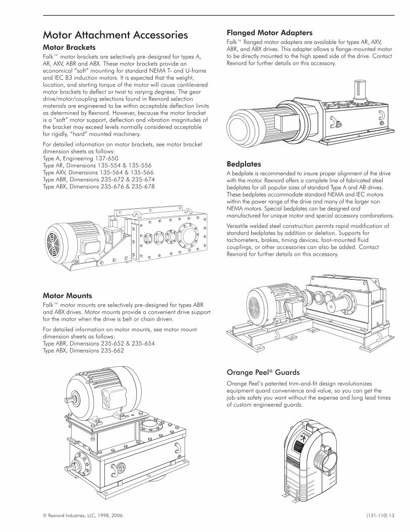
Motor Attachment AccessoriesMotor BracketsFalk™ motor brackets are selectively pre-designed for types A,AR, AXV, ABR and ABX. These motor brackets provide aneconomical “soft” mounting for standard NEMA T- and U-frameand IEC B3 induction motors. It is expected that the weight,location, and starting torque of the motor will cause cantileveredmotor brackets to deflect or twist to varying degrees. The geardrive/motor/coupling selections found in Rexnord selectionmaterials are engineered to be within acceptable deflection limitsas determined by Rexnord. However, because the motor bracketis a “soft” motor support, deflection and vibration magnitudes ofthe bracket may exceed levels normally considered acceptablefor rigidly, “hard” mounted machinery.
For detailed information on motor brackets, see motor bracketdimension sheets as follows:Type A, Engineering 137-650Type AR, Dimensions 135-554 & 135-556Type AXV, Dimensions 135-564 & 135-566Type ABR, Dimensions 235-672 & 235-674Type ABX, Dimensions 235-676 & 235-678
Motor MountsFalk™ motor mounts are selectively pre-designed for types ABRand ABX drives. Motor mounts provide a convenient drive supportfor the motor when the drive is belt or chain driven.
For detailed information on motor mounts, see motor mountdimension sheets as follows:Type ABR, Dimensions 235-652 & 235-654Type ABX, Dimensions 235-662
Flanged Motor AdaptersFalk™ flanged motor adapters are available for types AR, AXV,ABR, and ABX drives. This adapter allows a flange-mounted motorto be directly mounted to the high speed side of the drive. ContactRexnord for further details on this accessory.
BedplatesA bedplate is recommended to insure proper alignment of the drivewith the motor. Rexnord offers a complete line of fabricated steelbedplates for all popular sizes of standard Type A and AB drives.These bedplates accommodate standard NEMA and IEC motorswithin the power range of the drive and many of the larger nonNEMA motors. Special bedplates can be designed andmanufactured for unique motor and special accessory combinations.
Versatile welded steel construction permits rapid modification ofstandard bedplates by addition or deletion. Supports fortachometers, brakes, timing devices, foot-mounted fluidcouplings, or other accessories can also be added. ContactRexnord for further details on this accessory.
Orange Peel® Guards
Orange Peel’s patented trim-and-fit design revolutionizesequipment quard convenience and value, so you can get thejob-site safety you want without the expense and long lead timesof custom engineered guards.
© Rexnord Industries, LLC, 1998, 2006. (131-110) 13
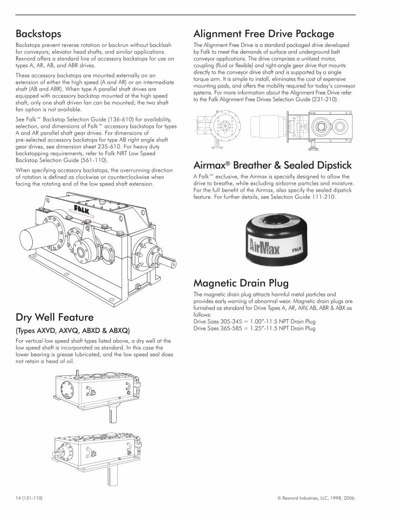
BackstopsBackstops prevent reverse rotation or backrun without backlashfor conveyors, elevator head shafts, and similar applications.Rexnord offers a standard line of accessory backstops for use ontypes A, AR, AB, and ABR drives.
These accessory backstops are mounted externally on anextension of either the high speed (A and AR) or an intermediateshaft (AB and ABR). When type A parallel shaft drives areequipped with accessory backstop mounted at the high speedshaft, only one shaft driven fan can be mounted; the two shaftfan option is not available.
See Falk™ Backstop Selection Guide (136-610) for availability,selection, and dimensions of Falk™ accessory backstops for typesA and AR parallel shaft gear drives. For dimensions ofpre-selected accessory backstops for type AB right angle shaftgear drives, see dimension sheet 235-610. For heavy dutybackstopping requirements, refer to Falk NRT Low SpeedBackstop Selection Guide (561-110).
When specifying accessory backstops, the overrunning directionof rotation is defined as clockwise or counterclockwise whenfacing the rotating end of the low speed shaft extension.
Dry Well Feature(Types AXVD, AXVQ, ABXD & ABXQ)
For vertical low speed shaft types listed above, a dry well at thelow speed shaft is incorporated as standard. In this case thelower bearing is grease lubricated, and the low speed seal doesnot retain a head of oil.
Alignment Free Drive PackageThe Alignment Free Drive is a standard packaged drive developedby Falk to meet the demands of surface and underground beltconveyor applications. The drive comprises a unitized motor,coupling (fluid or flexible) and right-angle gear drive that mountsdirectly to the conveyor drive shaft and is supported by a singletorque arm. It is simple to install, eliminates the cost of expensivemounting pads, and offers the mobility required for today’s conveyorsystems. For more information about the Alignment Free Drive referto the Falk Alignment Free Drives Selection Guide (231-210).
Airmax® Breather & Sealed DipstickA Falk™ exclusive, the Airmax is specially designed to allow thedrive to breathe, while excluding airborne particles and moisture.For the full benefit of the Airmax, also specify the sealed dipstickfeature. For further details, see Selection Guide 111-210.
Magnetic Drain PlugThe magnetic drain plug attracts harmful metal particles andprovides early warning of abnormal wear. Magnetic drain plugs arefurnished as standard for Drive Types A, AR, AXV, AB, ABR & ABX asfollows:Drive Sizes 305-345 = 1.00”-11.5 NPT Drain PlugDrive Sizes 365-585 = 1.25”-11.5 NPT Drain Plug
14 (131-110) © Rexnord Industries, LLC, 1998, 2006.
© Rexnord Industries, LLC, 1998, 2006. (131-110) 15
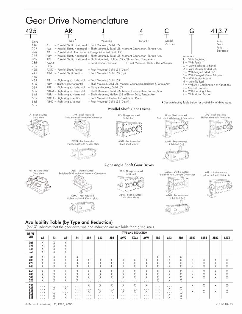
Gear Drive Nomenclature
Parallel Shaft Gear Drives
Right Angle Shaft Gear Drives
ABXU - Foot mountedSolid shaft (up)
A - Foot mountedSolid shaft
AM - Shaft mountedSolid shaft with Moment Connection
AR - Flange mountedSolid shaft
ARM - Shaft mountedSolid shaft with Moment Connection
ARJ - Shaft mountedHollow shaft with Shrink disc
AXVQ - Foot mountedHollow Shaft with Keeper plate
AXVD - Foot mountedSolid shaft (down)
AXVU - Foot mountedSolid shaft (up)
AB - Foot mountedSolid shaft
ABM - Shaft mountedBedplate/Solid shaft with Moment Connection
ABR - Flange mountedSolid shaft
ABRM - Shaft mountedSolid shaft with Moment Connection
ABRJ - Shaft mountedHollow shaft with Shrink disc
ABXQ - Foot mountedHollow shaft with Keeper plate
Availability Table (by Type and Reduction)(An“ X” indicates that the gear drive type and reduction are available for a given size.)
DRIVESIZE
TYPE AND REDUCTION
A1 A2 A3 A4 AR2 AR3 AR4 AXV2 AXV3 AXV4 AB2 AB3 AB4 ABR3 ABR4 ABX3 ABX4
305 X X X325 X X X345 X X X365 X X X
385 X X X X . . . . . . . . . . . . . . . . . . X X X405 X X X X X X X X X X X X X X X X X425 X X X X X X X X X X X X X X X X X445 X X X X X X X X X X X X X X X X X
465 X X X X X X X X X X X X X X X X X485 X X X X X X X X X X X X X X X X X505 X X X X X X X X X X X X X X X X X525 X X X X . . . . . . . . . . . . . . . . . . X X X
535 . . . . . . . . . . . . X X X X X X . . . . . . . . . X X X X545 . . . X X . . . . . . . . . . . . . . . . . . . . . . . . X X555 . . . . . . . . . . . . X X X X X X . . . . . . . . . X X X X565 . . . X X . . . . . . . . . . . . . . . . . . . . . . . . X X585 . . . X X . . . . . . . . . . . . . . . . . . . . . . . . X X
ABXD - Foot mountedSolid shaft (down)
DriveSize
305
325
345
365
385
405
425
445
465
485
505
525
535
545
555
565
585
Type � Mounting ModelA, B, C,
VariationsA = With BackstopB = With Fan(s)C = With Backstop & Fan(s)D = With Double Ended LSSE = With Single Ended HSSF = With Flanged Motor AdapterG = With Motor MountH = With Tie RodR = With Any Combination of VariationsS = Special FeaturesT = With Cooling TubesZ = With Motor Bracket
RatioExactRatioExpressed
A = Parallel Shaft, Horizontal + Foot Mounted, Solid LSS
AM = Parallel Shaft, Horizontal + Shaft Mounted, Solid LSS, Moment Connection, Torque Arm
AR = Parallel shaft, Horizontal + Flange Mounted, Solid LSS
ARM = Parallel Shaft, Horizontal + Shaft Mounted, Solid LSS, Moment Connection, Torque Arm
ARJ = Parallel Shaft, Horizontal + Shaft Mounted, Hollow LSS w/Shrink Disc, Torque Arm
AXVQ = Parallel Shaft, Vertical + Foot Mounted, Hollow LSS w/KeeperPlate
AXVD = Parallel Shaft, Vertical + Foot Mounted, Solid LSS (Down)
AXVU = Parallel Shaft, Vertical + Foot Mounted, Solid LSS (Up)
AB = Right Angle, Horizontal + Foot Mounted, Solid LSS
ABM = Right Angle, Horizontal + Shaft Mounted, Solid LSS, Moment Connection, Bedplate & Torque Arm
ABR = Right Angle, Horizontal + Flange Mounted, Solid LSS
ABRM = Right Angle, Horizontal + Shaft Mounted, Solid LSS, Moment Connection, Torque Arm
ABRJ = Right Angle, Horizontal + Shaft Mounted, Hollow LSS w/Shrink Disc, Torque Arm
ABXQ = Right Angle, Vertical + Foot Mounted, Hollow LSS w/Keeper Plate
ABXD = Right Angle, Vertical + Foot Mounted, Solid LSS (Down) � See Availability Table below for availability of drive types.
Reductio
425 AR J 4 C G 413.7
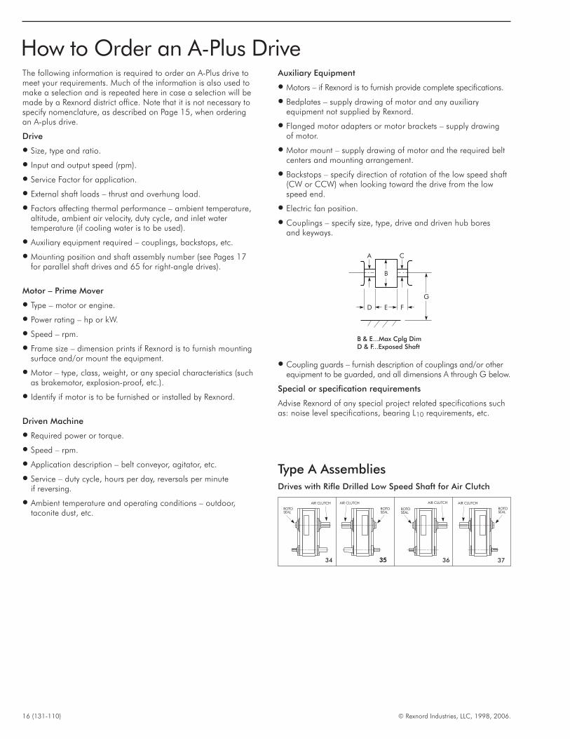
The following information is required to order an A-Plus drive tomeet your requirements. Much of the information is also used tomake a selection and is repeated here in case a selection will bemade by a Rexnord district office. Note that it is not necessary tospecify nomenclature, as described on Page 15, when orderingan A-plus drive.
Drive
� Size, type and ratio.
� Input and output speed (rpm).
� Service Factor for application.
� External shaft loads – thrust and overhung load.
� Factors affecting thermal performance – ambient temperature,altitude, ambient air velocity, duty cycle, and inlet watertemperature (if cooling water is to be used).
� Auxiliary equipment required – couplings, backstops, etc.
� Mounting position and shaft assembly number (see Pages 17for parallel shaft drives and 65 for right-angle drives).
Motor – Prime Mover
� Type – motor or engine.
� Power rating – hp or kW.
� Speed – rpm.
� Frame size – dimension prints if Rexnord is to furnish mountingsurface and/or mount the equipment.
� Motor – type, class, weight, or any special characteristics (suchas brakemotor, explosion-proof, etc.).
� Identify if motor is to be furnished or installed by Rexnord.
Driven Machine
� Required power or torque.
� Speed – rpm.
� Application description – belt conveyor, agitator, etc.
� Service – duty cycle, hours per day, reversals per minuteif reversing.
� Ambient temperature and operating conditions – outdoor,taconite dust, etc.
Auxiliary Equipment
� Motors – if Rexnord is to furnish provide complete specifications.
� Bedplates – supply drawing of motor and any auxiliaryequipment not supplied by Rexnord.
� Flanged motor adapters or motor brackets – supply drawingof motor.
� Motor mount – supply drawing of motor and the required beltcenters and mounting arrangement.
� Backstops – specify direction of rotation of the low speed shaft(CW or CCW) when looking toward the drive from the lowspeed end.
� Electric fan position.
� Couplings – specify size, type, drive and driven hub boresand keyways.
� Coupling guards – furnish description of couplings and/or otherequipment to be guarded, and all dimensions A through G below.
Special or specification requirements
Advise Rexnord of any special project related specifications suchas: noise level specifications, bearing L10 requirements, etc.
16 (131-110) © Rexnord Industries, LLC, 1998, 2006.
How to Order an A-Plus Drive
A C
B
D E F
G
B & E...Max Cplg DimD & F...Exposed Shaft
AIR CLUTCH
ROTOSEAL
AIR CLUTCH
ROTOSEAL
373635
ROTOSEAL
AIR CLUTCHAIR CLUTCH
ROTOSEAL
3534
Type A AssembliesDrives with Rifle Drilled Low Speed Shaft for Air Clutch
© Rexnord Industries, LLC, 1998, 2006. (131-110) 17
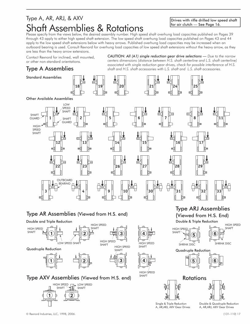
Type A, AR, ARJ, & AXV
Shaft Assemblies & RotationsPlease specify from the views below, the desired assembly number. High speed shaft overhung load capacities published on Pages 39through 43 apply to either high speed shaft extension. The low speed shaft overhung load capacities published on Pages 43 and 44apply to the low speed shaft extensions below with heavy arrows. Published overhung load capacities may be increased when anoutboard bearing is used. Consult Rexnord for overhung load capacities of low speed shaft extensions without the heavy arrow, as theyare less than the heavy arrow extensions.
Contact Rexnord for inclined, wall mounted,or other non-standard orientations.
Type A Assemblies
Standard Assemblies
Other Available Assemblies
CAUTION: All (A1) single reduction gear drive selections — Due to the narrowcenters dimensions (distance between H.S. shaft centerline and L.S. shaft centerline)associated with single reduction gear drives, check for possible interference of H.S.shaft and H.S. shaft accessories with L.S. shaft and L.S. shaft accessories.
SHAFTGUARD
LOWSPEEDSHAFT
SHAFTGUARD
HIGHSPEEDSHAFT
OUTBOARDBEARING
Type AR Assemblies (Viewed from H.S. end)
Double and Triple Reduction
Quadruple Reduction
Type ARJ Assemblies(Viewed from H.S. End)
Type AXV Assemblies (Viewed from H.S. end)
LOW SPEED SHAFT
HIGH SPEEDSHAFT
HIGH SPEEDSHAFT
HIGH SPEEDSHAFT
HIGH SPEEDSHAFT
HIGH SPEEDSHAFT
LOW SPEEDSHAFT
Double & Triple Reduction
Quadruple Reduction
HIGH SPEEDSHAFTHIGH SPEED
SHAFT
SHRINK DISC SHRINK DISCHIGH SPEEDSHAFT
HIGH SPEEDSHAFT
Single & Triple ReductionA, AR,ARJ, AXV Gear Drives
Double & Quadruple ReductionA, AR,ARJ, AXV Gear Drives
Rotations
Drives with rifle drilled low speed shaftfor air clutch — See Page 16.
18 (131-110) © Rexnord Industries, LLC, 1998, 2006.
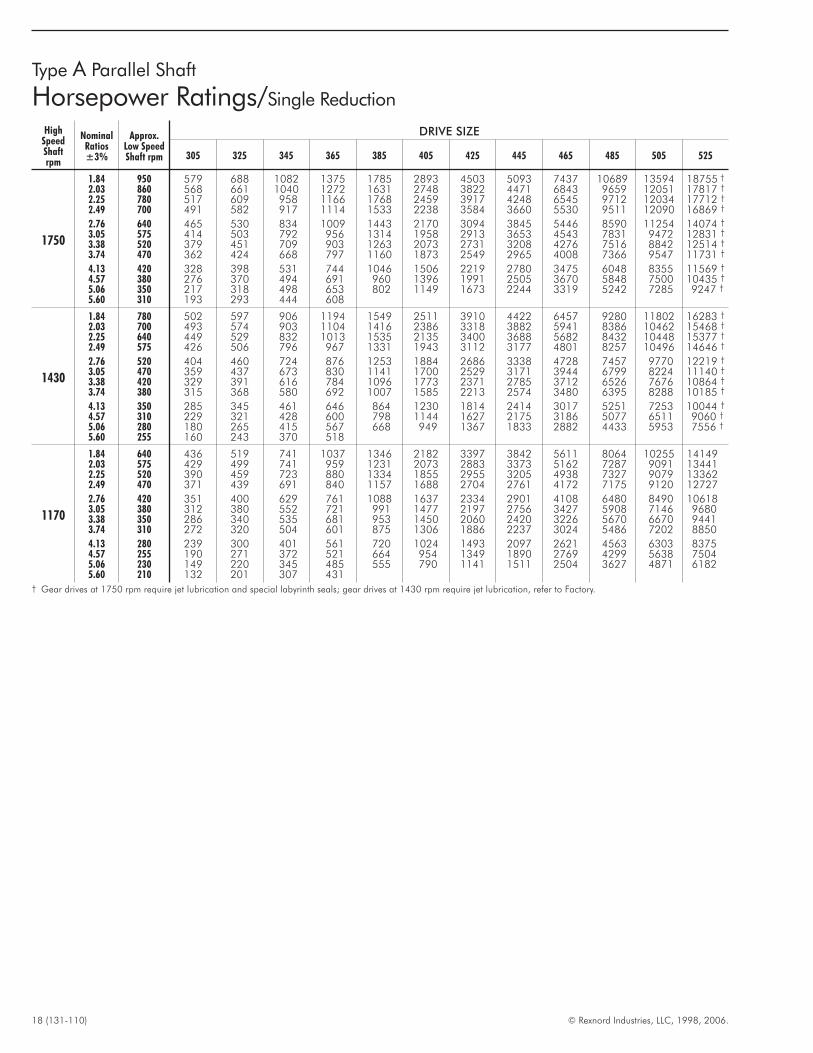
Type A Parallel Shaft
Horsepower Ratings/Single Reduction
HighSpeedShaftrpm
NominalRatios±3%
Approx.Low SpeedShaft rpm
DRIVE SIZE
305 325 345 365 385 405 425 445 465 485 505 525
1750
1.84 950 579 688 1082 1375 1785 2893 4503 5093 7437 10689 13594 18755 †
2.03 860 568 661 1040 1272 1631 2748 3822 4471 6843 9659 12051 17817 †
2.25 780 517 609 958 1166 1768 2459 3917 4248 6545 9712 12034 17712 †
2.49 700 491 582 917 1114 1533 2238 3584 3660 5530 9511 12090 16869 †
2.76 640 465 530 834 1009 1443 2170 3094 3845 5446 8590 11254 14074 †
3.05 575 414 503 792 956 1314 1958 2913 3653 4543 7831 9472 12831 †
3.38 520 379 451 709 903 1263 2073 2731 3208 4276 7516 8842 12514 †
3.74 470 362 424 668 797 1160 1873 2549 2965 4008 7366 9547 11731 †
4.13 420 328 398 531 744 1046 1506 2219 2780 3475 6048 8355 11569 †
4.57 380 276 370 494 691 960 1396 1991 2505 3670 5848 7500 10435 †
5.06 350 217 318 498 653 802 1149 1673 2244 3319 5242 7285 9247 †
5.60 310 193 293 444 608
1430
1.84 780 502 597 906 1194 1549 2511 3910 4422 6457 9280 11802 16283 †
2.03 700 493 574 903 1104 1416 2386 3318 3882 5941 8386 10462 15468 †
2.25 640 449 529 832 1013 1535 2135 3400 3688 5682 8432 10448 15377 †
2.49 575 426 506 796 967 1331 1943 3112 3177 4801 8257 10496 14646 †
2.76 520 404 460 724 876 1253 1884 2686 3338 4728 7457 9770 12219 †
3.05 470 359 437 673 830 1141 1700 2529 3171 3944 6799 8224 11140 †
3.38 420 329 391 616 784 1096 1773 2371 2785 3712 6526 7676 10864 †
3.74 380 315 368 580 692 1007 1585 2213 2574 3480 6395 8288 10185 †
4.13 350 285 345 461 646 864 1230 1814 2414 3017 5251 7253 10044 †
4.57 310 229 321 428 600 798 1144 1627 2175 3186 5077 6511 9060 †
5.06 280 180 265 415 567 668 949 1367 1833 2882 4433 5953 7556 †
5.60 255 160 243 370 518
1170
1.84 640 436 519 741 1037 1346 2182 3397 3842 5611 8064 10255 141492.03 575 429 499 741 959 1231 2073 2883 3373 5162 7287 9091 134412.25 520 390 459 723 880 1334 1855 2955 3205 4938 7327 9079 133622.49 470 371 439 691 840 1157 1688 2704 2761 4172 7175 9120 12727
2.76 420 351 400 629 761 1088 1637 2334 2901 4108 6480 8490 106183.05 380 312 380 552 721 991 1477 2197 2756 3427 5908 7146 96803.38 350 286 340 535 681 953 1450 2060 2420 3226 5670 6670 94413.74 310 272 320 504 601 875 1306 1886 2237 3024 5486 7202 8850
4.13 280 239 300 401 561 720 1024 1493 2097 2621 4563 6303 83754.57 255 190 271 372 521 664 954 1349 1890 2769 4299 5638 75045.06 230 149 220 345 485 555 790 1141 1511 2504 3627 4871 61825.60 210 132 201 307 431
† Gear drives at 1750 rpm require jet lubrication and special labyrinth seals; gear drives at 1430 rpm require jet lubrication, refer to Factory.
© Rexnord Industries, LLC, 1998, 2006. (131-110) 19
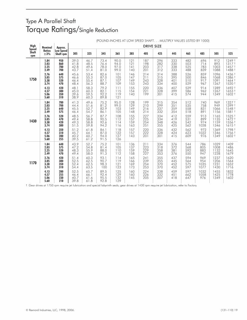
Type A Parallel Shaft
Torque Ratings/Single Reduction
(POUND-INCHES AT LOW SPEED SHAFT. . . MULTIPLY VALUES LISTED BY 1000)
HighSpeedShaftrpm
NominalRatios±3%
Approx.Low SpeedShaft rpm
DRIVE SIZE
305 325 345 365 385 405 425 445 465 485 505 525
1750
1.84 950 39.0 46.7 73.4 90.0 121 187 296 333 482 696 912 1249 †
2.03 860 41.8 48.5 76.4 94.0 121 198 282 330 503 714 893 1317 †
2.25 780 42.8 49.6 78.0 97.0 141 203 317 338 525 783 1003 1457 †
2.49 700 43.7 51.4 81.0 99.0 140 201 312 333 488 839 1088 1488 †
2.76 640 45.6 53.4 82.6 101 146 214 314 388 526 859 1096 1436 †
3.05 575 46.6 55.3 87.0 105 147 211 315 395 500 846 1068 1386 †
3.38 520 46.4 55.4 87.1 107 149 243 328 401 510 917 1091 1464 †
3.74 470 48.4 56.3 88.7 109 153 243 334 400 529 967 1267 1520 †
4.13 420 48.1 58.3 79.2 111 155 220 336 407 529 914 1289 1692 †
4.57 380 45.0 60.3 82.1 115 154 221 328 399 586 962 1267 1653 †
5.06 350 39.6 59.5 92.2 119 140 199 301 415 574 944 1349 1602 †
5.60 310 38.9 60.3 89.8 121
1430
1.84 780 41.3 49.6 75.2 95.0 128 199 315 354 512 740 969 1327 †
2.03 700 44.4 51.6 81.2 99.0 129 210 299 351 535 758 949 1399 †
2.25 640 45.5 52.7 82.9 103 149 216 337 359 558 831 1066 1548 †
2.49 575 46.4 54.7 86.1 105 148 214 332 354 518 891 1156 1581 †
2.76 520 48.5 56.7 87.7 108 155 227 334 412 559 913 1165 1525 †
3.05 470 49.4 58.8 90.5 112 157 225 334 419 531 899 1135 1472 †
3.38 420 49.3 58.8 92.6 114 159 254 348 426 542 974 1159 1556 †
3.74 380 51.5 59.8 94.2 116 163 251 355 425 562 1028 1346 1615 †
4.13 350 51.2 61.8 84.1 118 157 220 336 432 562 972 1369 1798 †
4.57 310 45.7 64.1 87.0 122 157 222 328 424 623 1022 1346 1756 †
5.06 280 40.2 60.7 94.0 127 143 201 301 415 609 976 1349 1602 †
5.60 255 39.5 61.2 91.5 126
1170
1.84 640 43.9 52.7 75.2 101 136 211 334 376 544 786 1029 14092.03 575 47.2 54.8 81.4 105 137 223 318 372 568 805 1008 14862.25 520 48.3 55.9 88.0 110 159 229 358 381 592 883 1132 16452.49 470 49.4 58.0 91.3 112 158 227 353 376 550 947 1228 1679
2.76 420 51.4 60.3 93.1 114 165 241 355 437 594 969 1237 16203.05 380 52.5 62.5 90.7 119 166 239 355 445 564 954 1206 15643.38 350 52.4 62.5 98.3 121 169 254 370 452 575 1035 1231 16523.74 310 54.4 63.5 100 123 173 253 370 452 597 1077 1430 1716
4.13 280 52.5 65.7 89.5 125 160 224 338 459 597 1032 1455 18324.57 255 46.4 66.1 92.4 129 160 226 332 451 662 1058 1425 17785.06 230 40.7 61.6 95.5 132 145 205 307 418 647 976 1349 16025.60 210 39.8 61.8 92.8 129
† Gear drives at 1750 rpm require jet lubrication and special labyrinth seals; gear drives at 1430 rpm require jet lubrication, refer to Factory.
20 (131-110) © Rexnord Industries, LLC, 1998, 2006.
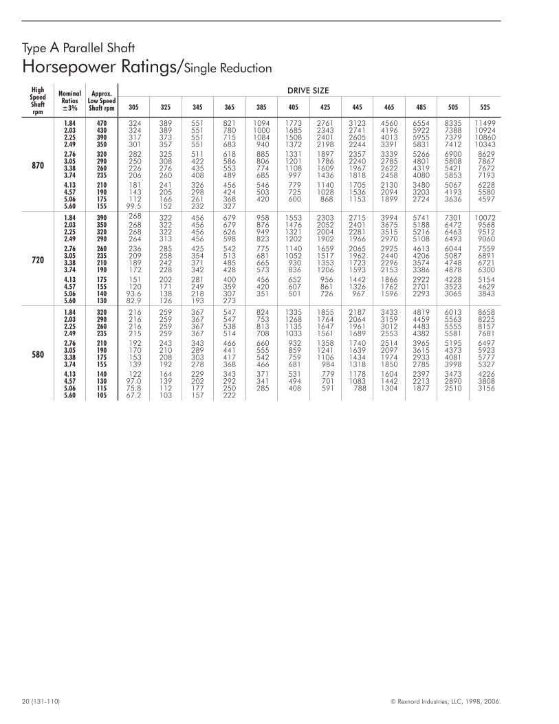
Type A Parallel Shaft
Horsepower Ratings/Single Reduction
HighSpeedShaftrpm
NominalRatios±3%
Approx.Low SpeedShaft rpm
DRIVE SIZE
305 325 345 365 385 405 425 445 465 485 505 525
870
1.84 470 324 389 551 821 1094 1773 2761 3123 4560 6554 8335 114992.03 430 324 389 551 780 1000 1685 2343 2741 4196 5922 7388 109242.25 390 317 373 551 715 1084 1508 2401 2605 4013 5955 7379 108602.49 350 301 357 551 683 940 1372 2198 2244 3391 5831 7412 10343
2.76 320 282 325 511 618 885 1331 1897 2357 3339 5266 6900 86293.05 290 250 308 422 586 806 1201 1786 2240 2785 4801 5808 78673.38 260 226 276 435 553 774 1108 1609 1967 2622 4319 5421 76723.74 235 206 260 408 489 685 997 1436 1818 2458 4080 5853 7193
4.13 210 181 241 326 456 546 779 1140 1705 2130 3480 5067 62284.57 190 143 205 298 424 503 725 1028 1536 2094 3203 4193 55805.06 175 112 166 261 368 420 600 868 1153 1899 2724 3636 45975.60 155 99.5 152 232 327
720
1.84 390 268 322 456 679 958 1553 2303 2715 3994 5741 7301 100722.03 350 268 322 456 679 876 1476 2052 2401 3675 5188 6472 95682.25 320 268 322 456 626 949 1321 2004 2281 3515 5216 6463 95122.49 290 264 313 456 598 823 1202 1902 1966 2970 5108 6493 9060
2.76 260 236 285 425 542 775 1140 1659 2065 2925 4613 6044 75593.05 235 209 258 354 513 681 1052 1517 1962 2440 4206 5087 68913.38 210 189 242 371 485 665 930 1353 1723 2296 3574 4748 67213.74 190 172 228 342 428 573 836 1206 1593 2153 3386 4878 6300
4.13 175 151 202 281 400 456 652 956 1442 1866 2922 4228 51544.57 155 120 171 249 359 420 607 861 1326 1762 2701 3523 46295.06 140 93.6 138 218 307 351 501 726 967 1596 2293 3065 38435.60 130 82.9 126 193 273
580
1.84 320 216 259 367 547 824 1335 1855 2187 3433 4819 6013 86582.03 290 216 259 367 547 753 1268 1764 2064 3159 4459 5563 82252.25 260 216 259 367 538 813 1135 1647 1961 3012 4483 5555 81572.49 235 215 259 367 514 708 1033 1561 1689 2553 4382 5581 7681
2.76 210 192 243 343 466 660 932 1358 1740 2514 3965 5195 64973.05 190 170 210 289 441 555 859 1241 1639 2097 3615 4373 59233.38 175 153 208 303 417 542 759 1106 1434 1974 2933 4081 57773.74 155 139 192 278 368 466 681 984 1318 1850 2785 3998 5327
4.13 140 122 164 229 343 371 531 779 1178 1604 2397 3473 42264.57 130 97.0 139 202 292 341 494 701 1083 1442 2213 2890 38085.06 115 75.8 112 177 250 285 408 591 788 1304 1877 2510 31565.60 105 67.2 103 157 222
© Rexnord Industries, LLC, 1998, 2006. (131-110) 21
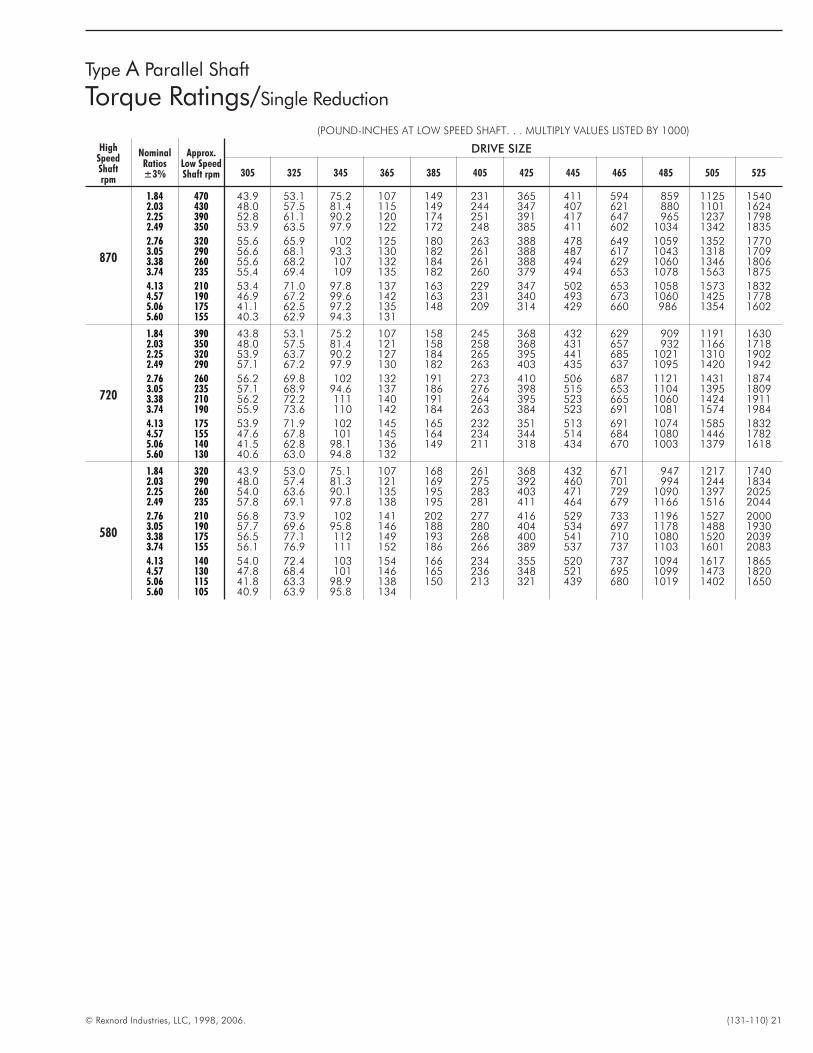
Type A Parallel Shaft
Torque Ratings/Single Reduction
(POUND-INCHES AT LOW SPEED SHAFT. . . MULTIPLY VALUES LISTED BY 1000)
HighSpeedShaftrpm
NominalRatios±3%
Approx.Low SpeedShaft rpm
DRIVE SIZE
305 325 345 365 385 405 425 445 465 485 505 525
870
1.84 470 43.9 53.1 75.2 107 149 231 365 411 594 859 1125 15402.03 430 48.0 57.5 81.4 115 149 244 347 407 621 880 1101 16242.25 390 52.8 61.1 90.2 120 174 251 391 417 647 965 1237 17982.49 350 53.9 63.5 97.9 122 172 248 385 411 602 1034 1342 1835
2.76 320 55.6 65.9 102 125 180 263 388 478 649 1059 1352 17703.05 290 56.6 68.1 93.3 130 182 261 388 487 617 1043 1318 17093.38 260 55.6 68.2 107 132 184 261 388 494 629 1060 1346 18063.74 235 55.4 69.4 109 135 182 260 379 494 653 1078 1563 1875
4.13 210 53.4 71.0 97.8 137 163 229 347 502 653 1058 1573 18324.57 190 46.9 67.2 99.6 142 163 231 340 493 673 1060 1425 17785.06 175 41.1 62.5 97.2 135 148 209 314 429 660 986 1354 16025.60 155 40.3 62.9 94.3 131
720
1.84 390 43.8 53.1 75.2 107 158 245 368 432 629 909 1191 16302.03 350 48.0 57.5 81.4 121 158 258 368 431 657 932 1166 17182.25 320 53.9 63.7 90.2 127 184 265 395 441 685 1021 1310 19022.49 290 57.1 67.2 97.9 130 182 263 403 435 637 1095 1420 1942
2.76 260 56.2 69.8 102 132 191 273 410 506 687 1121 1431 18743.05 235 57.1 68.9 94.6 137 186 276 398 515 653 1104 1395 18093.38 210 56.2 72.2 111 140 191 264 395 523 665 1060 1424 19113.74 190 55.9 73.6 110 142 184 263 384 523 691 1081 1574 1984
4.13 175 53.9 71.9 102 145 165 232 351 513 691 1074 1585 18324.57 155 47.6 67.8 101 145 164 234 344 514 684 1080 1446 17825.06 140 41.5 62.8 98.1 136 149 211 318 434 670 1003 1379 16185.60 130 40.6 63.0 94.8 132
580
1.84 320 43.9 53.0 75.1 107 168 261 368 432 671 947 1217 17402.03 290 48.0 57.4 81.3 121 169 275 392 460 701 994 1244 18342.25 260 54.0 63.6 90.1 135 195 283 403 471 729 1090 1397 20252.49 235 57.8 69.1 97.8 138 195 281 411 464 679 1166 1516 2044
2.76 210 56.8 73.9 102 141 202 277 416 529 733 1196 1527 20003.05 190 57.7 69.6 95.8 146 188 280 404 534 697 1178 1488 19303.38 175 56.5 77.1 112 149 193 268 400 541 710 1080 1520 20393.74 155 56.1 76.9 111 152 186 266 389 537 737 1103 1601 2083
4.13 140 54.0 72.4 103 154 166 234 355 520 737 1094 1617 18654.57 130 47.8 68.4 101 146 165 236 348 521 695 1099 1473 18205.06 115 41.8 63.3 98.9 138 150 213 321 439 680 1019 1402 16505.60 105 40.9 63.9 95.8 134

22 (131-110) © Rexnord Industries, LLC, 1998, 2006.
Type A, AR & AXV Parallel Shaft
Horsepower Ratings/Double Reduction
HighSpeedShaftrpm
AVAILABILITY OF TYPES A / AR / AXV DOUBLE AND TRIPLE REDUCTION
TYPE 305 325 345 365 385 405 425 445 465 485 505 525 535 545 555 565 585
AllA X X X X X X X X X X X X . . . X . . . X XAR . . . . . . . . . . . . . . . X X X X X X . . . X . . . X . . . . . .AXV . . . . . . . . . . . . . . . X X X X X X . . . X . . . X . . . . . .
HighSpeedShaftrpm
NominalRatios±4%
Approx.Low
SpeedShaftrpm
DRIVE SIZE
305 325 345 365 385 405 425 445 465 485 505 525 535 545 555 565 585
1750
5.60 310 . . . . . . . . . . . . 628 919 1215 1668 2453 3688 5080 6976 7245 9010 9217 11022 152726.20 280 159 242 408 505 624 920 1215 1496 2323 3533 4766 6676 6965 8190 8948 10135 142326.86 255 159 228 389 455 577 883 1215 1442 2179 3363 5004 6036 6394 7868 7922 9559 145417.59 230 159 214 348 429 561 815 1054 1365 1965 3074 4240 5777 6027 7142 7766 8875 11969
8.40 210 159 215 324 402 512 769 1054 1296 1843 2925 4386 5087 5385 7001 6806 8273 123319.30 190 135 175 308 375 484 716 924 1226 1740 2625 3899 4807 5364 6179 6706 7987 11974
10.29 170 120 179 275 351 426 669 924 1099 1632 2498 3756 4231 5087 6055 6292 7453 1090011.39 155 119 154 216 338 401 632 896 1039 1433 2346 3336 4436 4807 5373 5844 6779 10316
12.61 140 113 146 216 304 384 550 781 991 1404 2232 3240 4151 4231 5264 5469 6403 994413.95 125 91.8 137 216 286 322 524 739 937 1237 1975 2742 3831 4151 4724 5190 6019 814815.44 115 94.4 136 191 268 309 441 592 852 1186 1882 2876 3439 3439 4625 4760 5575 840117.09 100 75.8 110 168 253 279 419 633 805 1045 1661 2577 3242 3439 4307 4474 5050 8090
18.91 90 70.6 109 159 201 267 370 579 729 1101 1609 2365 2973 3242 4014 4230 4805 764520.93 84 59.9 88.3 140 201 214 323 463 635 999 1448 2204 2690 3030 3819 3956 4295 659723.16 75 56.2 87.0 131 191 . . .
Consult Factory25.63 68 51.1 72.7 119 164 . . .
28.36 60 45.4 66.5 106 15731.39 56 36.9 61.7 94.4 13634.74 50 36.4 56.5 88.5 121
1430
5.60 255 . . . . . . . . . . . . 513 798 1055 1448 2130 3202 4411 6057 6290 7822 8002 9569 132596.20 230 130 210 348 439 510 798 1055 1299 2017 3067 4137 5796 6047 7110 7768 8799 123566.86 210 130 198 337 395 485 767 1055 1252 1892 2920 4345 5240 5551 6831 6878 8299 126247.59 190 130 186 303 372 458 708 915 1185 1706 2669 3681 5015 5232 6201 6742 7705 10391
8.40 170 130 187 282 349 419 667 915 1125 1600 2540 3808 4417 4675 6078 5909 7183 107059.30 155 111 152 254 325 395 621 803 1064 1511 2279 3385 4174 4657 5364 5822 6934 10395
10.29 140 98.7 148 227 305 348 552 790 954 1417 2169 3261 3673 4416 5257 5462 6470 946311.39 125 97.5 127 179 288 328 527 732 902 1244 2036 2896 3851 4173 4665 5073 5886 8956
12.61 115 92.0 127 179 264 314 458 653 860 1219 1937 2813 3604 3673 4570 4748 5559 863413.95 100 75.4 119 178 249 263 431 604 813 1074 1715 2381 3326 3604 4101 4506 5226 707415.44 90 77.2 112 157 233 252 366 484 740 1029 1634 2497 2985 2985 4016 4133 4840 729317.09 84 62.2 90.7 138 220 228 345 517 699 907 1442 2237 2776 2985 3739 3884 4385 7023
18.91 75 58.3 89.2 131 167 218 304 473 633 956 1397 1972 2462 2758 3485 3672 4171 663720.93 68 49.1 72.5 115 167 175 266 379 522 868 1231 1817 2219 2503 3316 3435 † 3545 544723.16 60 46.3 71.9 109 157 . . .
Consult Factory25.63 56 41.8 59.6 97.7 134 . . .
28.36 50 37.2 54.5 87.0 13031.39 45 30.4 50.6 77.9 11134.74 40 29.8 46.3 72.5 98.9
1170
5.60 210 . . . . . . . . . . . . 423 694 917 1258 1851 2782 3833 5263 5466 6797 6953 8315 115216.20 190 106 182 284 381 417 694 917 1129 1753 2665 3595 5037 5254 6178 6750 7646 107376.86 170 106 172 284 343 397 666 917 1088 1644 2537 3775 4554 4824 5935 5977 7212 109707.59 155 106 162 263 323 375 615 795 1030 1482 2319 3198 4358 4547 5388 5859 6695 9029
8.40 140 106 162 239 304 343 580 779 978 1390 2207 3309 3838 4062 5281 5135 6241 93029.30 125 91.4 132 210 283 323 516 675 925 1313 1980 2942 3627 4047 4662 5059 6026 9033
10.29 115 81.3 122 187 260 285 456 646 829 1231 1884 2834 3192 3838 4568 4746 5623 822311.39 100 79.8 104 149 236 268 435 599 784 1081 1770 2516 3347 3626 4054 4408 5114 7783
12.61 90 75.3 104 149 229 257 381 534 748 1060 1684 2445 3132 3192 3971 4126 4831 750213.95 84 62.0 103 146 216 216 355 494 707 933 1490 2069 2890 3132 3564 3916 4541 614715.44 75 63.1 91.7 129 197 206 304 396 643 895 1420 2170 2594 2594 3489 3591 4206 633817.09 68 51.1 74.5 113 187 186 283 423 607 788 1253 1944 2293 2594 3249 3375 † 3810 6103
18.91 60 48.1 73.2 107 138 178 250 387 550 798 1194 1626 2031 2277 3028 3191 † 3625 567320.93 56 40.3 59.5 94.2 138 143 218 310 429 722 1014 1498 1829 2066 2790 2917 † 2928 450023.16 50 38.2 59.3 89.8 129 . . .
Consult Factory25.63 45 34.3 48.8 80.2 110 . . .
28.36 40 30.5 44.7 71.4 10631.39 37 25.0 41.4 64.3 91.334.74 34 24.5 37.9 59.4 81.1
† For Size 555ARJ (hollow low speed shaft with shrink disc) the hp rating and torque rating are limited by the shrink disc, see Page 33 for instructions.
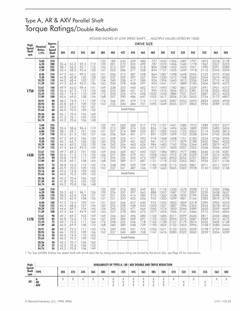
© Rexnord Industries, LLC, 1998, 2006. (131-110) 23
Type A, AR & AXV Parallel Shaft
Torque Ratings/Double Reduction
(POUND-INCHES AT LOW SPEED SHAFT. . . MULTIPLY VALUES LISTED BY 1000)
HighSpeedShaftrpm
NominalRatios±4%
Approx.Low
SpeedShaftrpm
DRIVE SIZE
305 325 345 365 385 405 425 445 465 485 505 525 535 545 555 565 585
1750
5.60 310 . . . . . . . . . . . . 133 185 245 339 486 727 1042 1356 1487 1797 1872 2218 31786.20 280 35.4 55.2 92.3 112 139 201 272 352 499 787 1070 1406 1540 1778 1967 2337 32236.86 255 38.7 56.2 95.1 116 143 213 297 366 518 806 1208 1452 1623 1941 1990 2391 35897.59 230 42.4 58.2 95.6 120 157 222 286 377 538 844 1157 1505 1649 1918 2112 2543 3349
8.40 210 47.2 65.1 99.2 125 151 226 313 387 558 864 1287 1598 1648 2055 2122 2575 37609.30 190 44.8 60.8 105 128 160 237 309 397 567 904 1330 1672 1768 2060 2264 2674 4003
10.29 170 44.0 68.4 102 131 154 240 338 417 589 926 1396 1640 1813 2206 2349 2710 412011.39 155 47.3 63.4 92.0 136 163 250 378 428 597 954 1441 1741 1889 2185 2406 2876 4275
12.61 140 49.9 65.0 99.4 141 169 238 352 440 602 977 1493 1782 1861 2339 2491 2951 431213.95 125 45.4 67.2 112 145 166 255 384 451 612 995 1376 1856 2013 2381 2578 3025 405215.44 115 50.7 74.4 110 149 173 240 335 474 636 1032 1540 1886 1931 2547 2687 3013 455317.09 100 45.6 69.0 108 154 168 257 390 486 647 1055 1617 2006 2130 2655 2754 3172 4807
18.91 90 48.2 74.9 111 139 174 246 391 479 715 1112 1625 2087 2253 2693 2834 3305 492020.93 84 45.8 69.7 109 152 152 235 340 484 701 1095 1649 2045 2277 2803 2955 3289 510523.16 75 45.2 73.0 107 161 . . .
Consult Factory25.63 68 46.0 70.0 109 152 . . .
28.36 60 45.1 70.4 106 16031.39 56 41.5 70.1 104 15334.74 50 45.2 70.6 106 148
1430
5.60 255 . . . . . . . . . . . . 132 197 260 360 517 773 1107 1441 1580 1910 1989 2357 33776.20 230 35.4 58.6 96.4 119 139 213 289 374 530 836 1136 1494 1636 1889 2090 2483 34246.86 210 38.7 59.7 101 124 147 227 316 389 550 857 1283 1543 1725 2063 2114 2540 38137.59 190 42.5 61.9 102 127 156 236 304 401 571 897 1229 1599 1752 2038 2244 2702 3558
8.40 170 47.2 69.3 106 133 151 239 332 411 593 918 1368 1698 1751 2183 2254 2736 39959.30 155 45.1 64.7 106 136 160 252 329 421 603 961 1413 1777 1879 2188 2405 2841 4252
10.29 140 44.3 69.2 103 139 154 242 354 443 626 984 1483 1742 1926 2344 2495 2879 437711.39 125 47.4 64.0 93.3 142 163 255 378 455 634 1013 1531 1850 2007 2322 2556 3056 4542
12.61 115 49.7 69.2 101 150 169 242 360 467 640 1037 1586 1893 1977 2486 2646 3135 458113.95 100 45.6 71.5 113 155 166 257 384 479 651 1058 1463 1972 2139 2529 2739 3214 430515.44 90 50.8 74.9 111 159 172 244 335 504 675 1097 1636 2003 2052 2707 2855 3201 483717.09 84 45.8 69.7 108 164 168 259 389 517 687 1121 1718 2102 2263 2821 2926 3371 5106
18.91 75 48.8 75.0 112 142 174 248 390 509 759 1182 1658 2115 2345 2861 3011 3511 522720.93 68 45.9 70.0 109 155 152 237 341 487 746 1139 1663 2065 2302 2978 3140 † 3322 515823.16 60 45.6 73.8 109 162 . . .
Consult Factory25.63 56 46.0 70.2 109 152 . . .
28.36 50 45.2 70.6 106 16231.39 45 41.8 70.4 105 15234.74 40 45.2 70.8 106 148
1170
5.60 210 . . . . . . . . . . . . 133 209 276 383 549 821 1176 1530 1678 2028 2112 2503 35866.20 190 35.3 62.1 96.1 126 139 226 307 397 563 888 1207 1587 1737 2007 2220 2638 36376.86 170 38.5 63.4 104 131 147 241 335 414 584 910 1363 1638 1832 2190 2246 2698 40507.59 155 42.3 65.9 108 135 157 251 323 425 606 952 1305 1699 1861 2164 2383 2870 3778
8.40 140 47.0 73.4 109 141 151 254 346 437 630 975 1452 1803 1859 2318 2395 2905 42439.30 125 45.4 68.6 107 144 160 255 338 448 640 1020 1501 1887 1996 2324 2554 3018 4516
10.29 115 44.6 69.7 104 145 154 245 353 471 664 1045 1576 1850 2046 2489 2650 3059 464911.39 100 47.4 64.1 94.9 142 163 257 378 483 673 1077 1626 1965 2131 2466 2715 3245 4824
12.61 90 49.7 69.2 103 159 169 246 360 496 680 1102 1685 2011 2099 2640 2811 3330 486513.95 84 45.8 75.6 113 164 167 259 384 509 691 1123 1553 2094 2272 2687 2909 3413 457215.44 75 50.7 75.0 111 164 172 248 335 536 718 1165 1738 2127 2179 2874 3032 3400 513817.09 68 46.0 69.9 108 170 168 260 389 548 729 1190 1824 2122 2403 2996 3108 † 3580 5424
18.91 60 49.2 75.2 111 143 174 249 390 541 775 1234 1671 2133 2376 3039 3198 † 3729 546020.93 56 46.1 70.2 109 156 152 237 340 489 758 1147 1676 2080 2322 3062 3259 † 3354 520923.16 50 46.0 74.4 110 163 . . .
Consult Factory25.63 45 46.2 70.3 109 152 . . .
28.36 40 45.3 70.7 106 16231.39 37 42.0 70.4 106 15334.74 34 45.5 70.8 106 149
† For Size 555ARJ (hollow low speed shaft with shrink disc) the hp rating and torque rating are limited by the shrink disc, see Page 33 for instructions.
HighSpeedShaftrpm
AVAILABILITY OF TYPES A / AR / AXV DOUBLE AND TRIPLE REDUCTION
TYPE 305 325 345 365 385 405 425 445 465 485 505 525 535 545 555 565 585
AllA X X X X X X X X X X X X . . . X . . . X XAR . . . . . . . . . . . . . . . X X X X X X . . . X . . . X . . . . . .AXV . . . . . . . . . . . . . . . X X X X X X . . . X . . . X . . . . . .
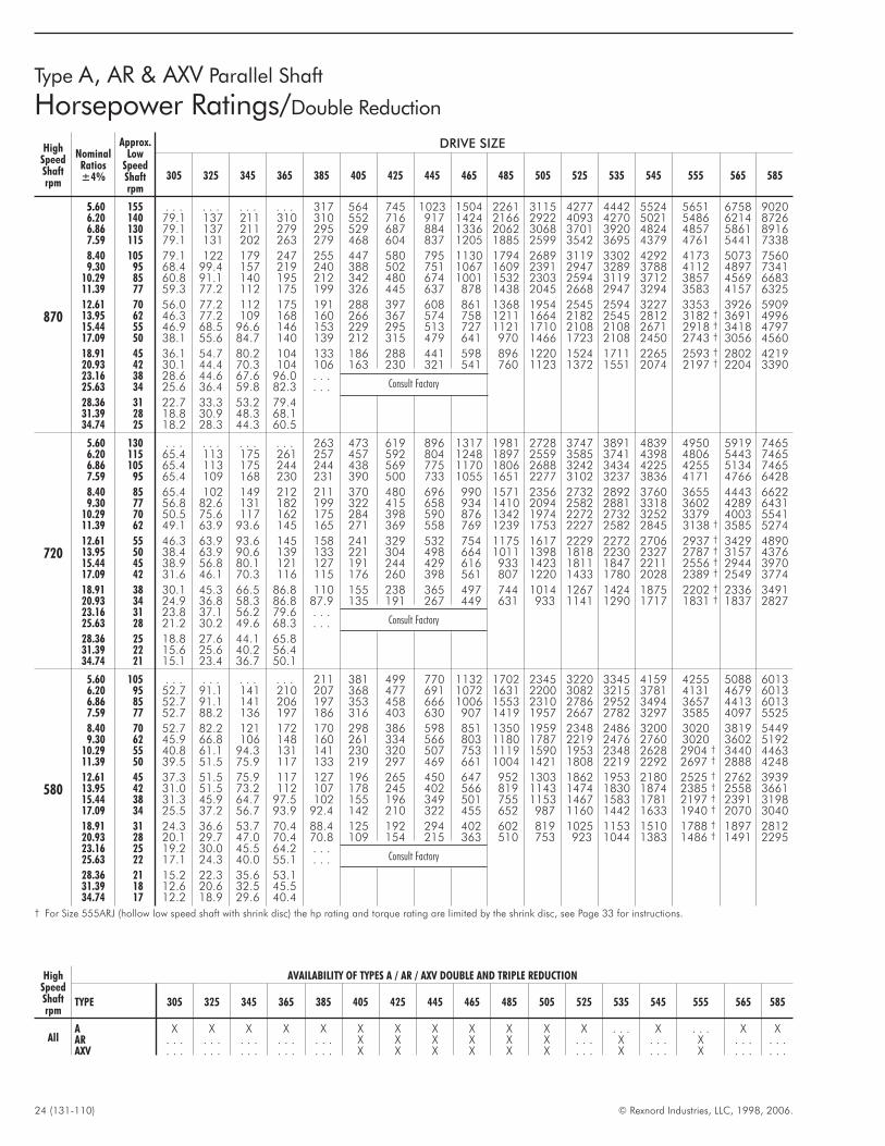
24 (131-110) © Rexnord Industries, LLC, 1998, 2006.
Type A, AR & AXV Parallel Shaft
Horsepower Ratings/Double Reduction
HighSpeedShaftrpm
NominalRatios±4%
Approx.Low
SpeedShaftrpm
DRIVE SIZE
305 325 345 365 385 405 425 445 465 485 505 525 535 545 555 565 585
870
5.60 155 . . . . . . . . . . . . 317 564 745 1023 1504 2261 3115 4277 4442 5524 5651 6758 90206.20 140 79.1 137 211 310 310 552 716 917 1424 2166 2922 4093 4270 5021 5486 6214 87266.86 130 79.1 137 211 279 295 529 687 884 1336 2062 3068 3701 3920 4824 4857 5861 89167.59 115 79.1 131 202 263 279 468 604 837 1205 1885 2599 3542 3695 4379 4761 5441 7338
8.40 105 79.1 122 179 247 255 447 580 795 1130 1794 2689 3119 3302 4292 4173 5073 75609.30 95 68.4 99.4 157 219 240 388 502 751 1067 1609 2391 2947 3289 3788 4112 4897 7341
10.29 85 60.8 91.1 140 195 212 342 480 674 1001 1532 2303 2594 3119 3712 3857 4569 668311.39 77 59.3 77.2 112 175 199 326 445 637 878 1438 2045 2668 2947 3294 3583 4157 6325
12.61 70 56.0 77.2 112 175 191 288 397 608 861 1368 1954 2545 2594 3227 3353 3926 590913.95 62 46.3 77.2 109 168 160 266 367 574 758 1211 1664 2182 2545 2812 3182 † 3691 499615.44 55 46.9 68.5 96.6 146 153 229 295 513 727 1121 1710 2108 2108 2671 2918 † 3418 479717.09 50 38.1 55.6 84.7 140 139 212 315 479 641 970 1466 1723 2108 2450 2743 † 3056 4560
18.91 45 36.1 54.7 80.2 104 133 186 288 441 598 896 1220 1524 1711 2265 2593 † 2802 421920.93 42 30.1 44.4 70.3 104 106 163 230 321 541 760 1123 1372 1551 2074 2197 † 2204 339023.16 38 28.6 44.6 67.6 96.0 . . .
Consult Factory25.63 34 25.6 36.4 59.8 82.3 . . .
28.36 31 22.7 33.3 53.2 79.431.39 28 18.8 30.9 48.3 68.134.74 25 18.2 28.3 44.3 60.5
720
5.60 130 . . . . . . . . . . . . 263 473 619 896 1317 1981 2728 3747 3891 4839 4950 5919 74656.20 115 65.4 113 175 261 257 457 592 804 1248 1897 2559 3585 3741 4398 4806 5443 74656.86 105 65.4 113 175 244 244 438 569 775 1170 1806 2688 3242 3434 4225 4255 5134 74657.59 95 65.4 109 168 230 231 390 500 733 1055 1651 2277 3102 3237 3836 4171 4766 6428
8.40 85 65.4 102 149 212 211 370 480 696 990 1571 2356 2732 2892 3760 3655 4443 66229.30 77 56.8 82.6 131 182 199 322 415 658 934 1410 2094 2582 2881 3318 3602 4289 6431
10.29 70 50.5 75.6 117 162 175 284 398 590 876 1342 1974 2272 2732 3252 3379 4003 554111.39 62 49.1 63.9 93.6 145 165 271 369 558 769 1239 1753 2227 2582 2845 3138 † 3585 5274
12.61 55 46.3 63.9 93.6 145 158 241 329 532 754 1175 1617 2229 2272 2706 2937 † 3429 489013.95 50 38.4 63.9 90.6 139 133 221 304 498 664 1011 1398 1818 2230 2327 2787 † 3157 437615.44 45 38.9 56.8 80.1 121 127 191 244 429 616 933 1423 1811 1847 2211 2556 † 2944 397017.09 42 31.6 46.1 70.3 116 115 176 260 398 561 807 1220 1433 1780 2028 2389 † 2549 3774
18.91 38 30.1 45.3 66.5 86.8 110 155 238 365 497 744 1014 1267 1424 1875 2202 † 2336 349120.93 34 24.9 36.8 58.3 86.8 87.9 135 191 267 449 631 933 1141 1290 1717 1831 † 1837 282723.16 31 23.8 37.1 56.2 79.6 . . .
Consult Factory25.63 28 21.2 30.2 49.6 68.3 . . .
28.36 25 18.8 27.6 44.1 65.831.39 22 15.6 25.6 40.2 56.434.74 21 15.1 23.4 36.7 50.1
580
5.60 105 . . . . . . . . . . . . 211 381 499 770 1132 1702 2345 3220 3345 4159 4255 5088 60136.20 95 52.7 91.1 141 210 207 368 477 691 1072 1631 2200 3082 3215 3781 4131 4679 60136.86 85 52.7 91.1 141 206 197 353 458 666 1006 1553 2310 2786 2952 3494 3657 4413 60137.59 77 52.7 88.2 136 197 186 316 403 630 907 1419 1957 2667 2782 3297 3585 4097 5525
8.40 70 52.7 82.2 121 172 170 298 386 598 851 1350 1959 2348 2486 3200 3020 3819 54499.30 62 45.9 66.8 106 148 160 261 334 566 803 1180 1787 2219 2476 2760 3020 3602 5192
10.29 55 40.8 61.1 94.3 131 141 230 320 507 753 1119 1590 1953 2348 2628 2904 † 3440 446311.39 50 39.5 51.5 75.9 117 133 219 297 469 661 1004 1421 1808 2219 2292 2697 † 2888 4248
12.61 45 37.3 51.5 75.9 117 127 196 265 450 647 952 1303 1862 1953 2180 2525 † 2762 393913.95 42 31.0 51.5 73.2 112 107 178 245 402 566 819 1143 1474 1830 1874 2385 † 2558 366115.44 38 31.3 45.9 64.7 97.5 102 155 196 349 501 755 1153 1467 1583 1781 2197 † 2391 319817.09 34 25.5 37.2 56.7 93.9 92.4 142 210 322 455 652 987 1160 1442 1633 1940 † 2070 3040
18.91 31 24.3 36.6 53.7 70.4 88.4 125 192 294 402 602 819 1025 1153 1510 1788 † 1897 281220.93 28 20.1 29.7 47.0 70.4 70.8 109 154 215 363 510 753 923 1044 1383 1486 † 1491 229523.16 25 19.2 30.0 45.5 64.2 . . .
Consult Factory25.63 22 17.1 24.3 40.0 55.1 . . .
28.36 21 15.2 22.3 35.6 53.131.39 18 12.6 20.6 32.5 45.534.74 17 12.2 18.9 29.6 40.4
† For Size 555ARJ (hollow low speed shaft with shrink disc) the hp rating and torque rating are limited by the shrink disc, see Page 33 for instructions.
HighSpeedShaftrpm
AVAILABILITY OF TYPES A / AR / AXV DOUBLE AND TRIPLE REDUCTION
TYPE 305 325 345 365 385 405 425 445 465 485 505 525 535 545 555 565 585
AllA X X X X X X X X X X X X . . . X . . . X XAR . . . . . . . . . . . . . . . X X X X X X . . . X . . . X . . . . . .AXV . . . . . . . . . . . . . . . X X X X X X . . . X . . . X . . . . . .
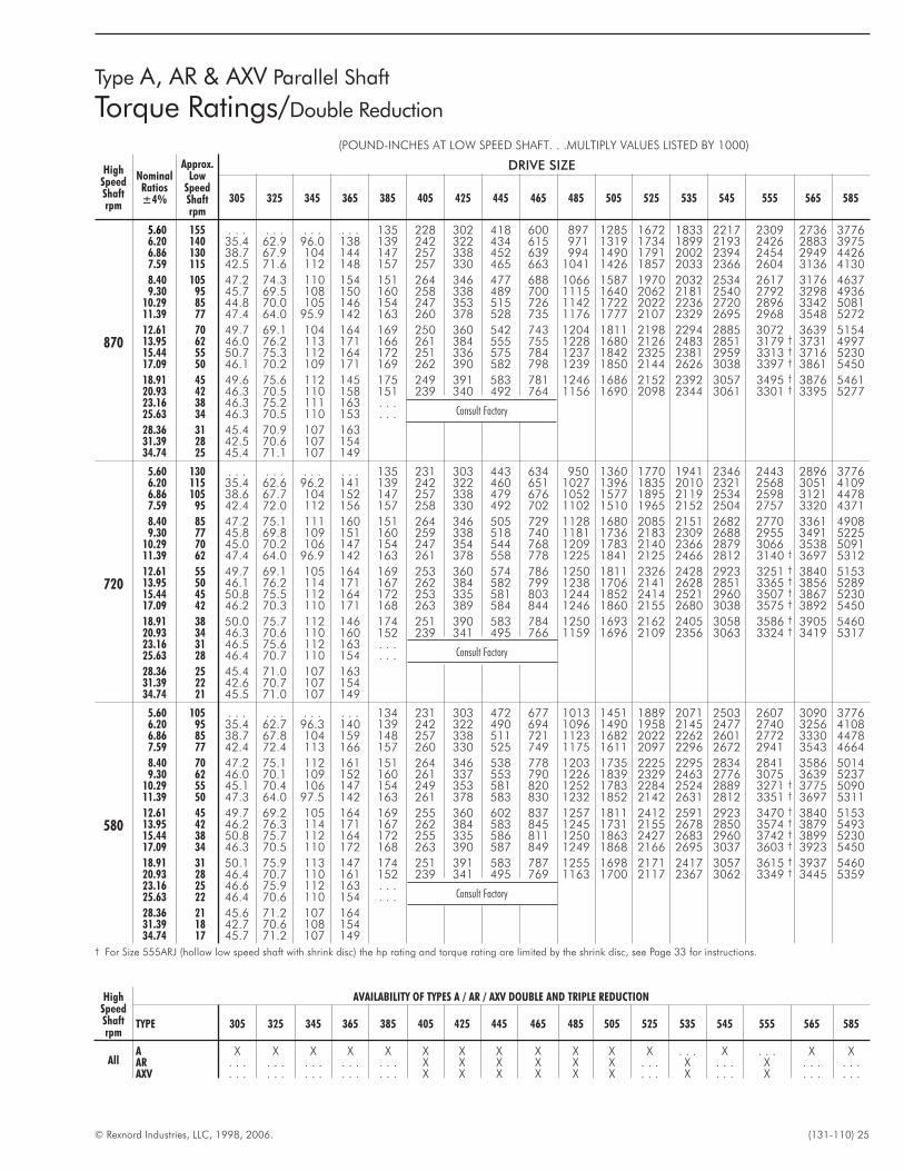
© Rexnord Industries, LLC, 1998, 2006. (131-110) 25
Type A, AR & AXV Parallel Shaft
Torque Ratings/Double Reduction
(POUND-INCHES AT LOW SPEED SHAFT. . .MULTIPLY VALUES LISTED BY 1000)
HighSpeedShaftrpm
NominalRatios±4%
Approx.Low
SpeedShaftrpm
DRIVE SIZE
305 325 345 365 385 405 425 445 465 485 505 525 535 545 555 565 585
870
5.60 155 . . . . . . . . . . . . 135 228 302 418 600 897 1285 1672 1833 2217 2309 2736 37766.20 140 35.4 62.9 96.0 138 139 242 322 434 615 971 1319 1734 1899 2193 2426 2883 39756.86 130 38.7 67.9 104 144 147 257 338 452 639 994 1490 1791 2002 2394 2454 2949 44267.59 115 42.5 71.6 112 148 157 257 330 465 663 1041 1426 1857 2033 2366 2604 3136 4130
8.40 105 47.2 74.3 110 154 151 264 346 477 688 1066 1587 1970 2032 2534 2617 3176 46379.30 95 45.7 69.5 108 150 160 258 338 489 700 1115 1640 2062 2181 2540 2792 3298 4936
10.29 85 44.8 70.0 105 146 154 247 353 515 726 1142 1722 2022 2236 2720 2896 3342 508111.39 77 47.4 64.0 95.9 142 163 260 378 528 735 1176 1777 2107 2329 2695 2968 3548 5272
12.61 70 49.7 69.1 104 164 169 250 360 542 743 1204 1811 2198 2294 2885 3072 3639 515413.95 62 46.0 76.2 113 171 166 261 384 555 755 1228 1680 2126 2483 2851 3179 † 3731 499715.44 55 50.7 75.3 112 164 172 251 336 575 784 1237 1842 2325 2381 2959 3313 † 3716 523017.09 50 46.1 70.2 109 171 169 262 390 582 798 1239 1850 2144 2626 3038 3397 † 3861 5450
18.91 45 49.6 75.6 112 145 175 249 391 583 781 1246 1686 2152 2392 3057 3495 † 3876 546120.93 42 46.3 70.5 110 158 151 239 340 492 764 1156 1690 2098 2344 3061 3301 † 3395 527723.16 38 46.3 75.2 111 163 . . .
Consult Factory25.63 34 46.3 70.5 110 153 . . .
28.36 31 45.4 70.9 107 16331.39 28 42.5 70.6 107 15434.74 25 45.4 71.1 107 149
720
5.60 130 . . . . . . . . . . . . 135 231 303 443 634 950 1360 1770 1941 2346 2443 2896 37766.20 115 35.4 62.6 96.2 141 139 242 322 460 651 1027 1396 1835 2010 2321 2568 3051 41096.86 105 38.6 67.7 104 152 147 257 338 479 676 1052 1577 1895 2119 2534 2598 3121 44787.59 95 42.4 72.0 112 156 157 258 330 492 702 1102 1510 1965 2152 2504 2757 3320 4371
8.40 85 47.2 75.1 111 160 151 264 346 505 729 1128 1680 2085 2151 2682 2770 3361 49089.30 77 45.8 69.8 109 151 160 259 338 518 740 1181 1736 2183 2309 2688 2955 3491 5225
10.29 70 45.0 70.2 106 147 154 247 354 544 768 1209 1783 2140 2366 2879 3066 3538 509111.39 62 47.4 64.0 96.9 142 163 261 378 558 778 1225 1841 2125 2466 2812 3140 † 3697 5312
12.61 55 49.7 69.1 105 164 169 253 360 574 786 1250 1811 2326 2428 2923 3251 † 3840 515313.95 50 46.1 76.2 114 171 167 262 384 582 799 1238 1706 2141 2628 2851 3365 † 3856 528915.44 45 50.8 75.5 112 164 172 253 335 581 803 1244 1852 2414 2521 2960 3507 † 3867 523017.09 42 46.2 70.3 110 171 168 263 389 584 844 1246 1860 2155 2680 3038 3575 † 3892 5450
18.91 38 50.0 75.7 112 146 174 251 390 583 784 1250 1693 2162 2405 3058 3586 † 3905 546020.93 34 46.3 70.6 110 160 152 239 341 495 766 1159 1696 2109 2356 3063 3324 † 3419 531723.16 31 46.5 75.6 112 163 . . .
Consult Factory25.63 28 46.4 70.7 110 154 . . .
28.36 25 45.4 71.0 107 16331.39 22 42.6 70.7 107 15434.74 21 45.5 71.0 107 149
580
5.60 105 . . . . . . . . . . . . 134 231 303 472 677 1013 1451 1889 2071 2503 2607 3090 37766.20 95 35.4 62.7 96.3 140 139 242 322 490 694 1096 1490 1958 2145 2477 2740 3256 41086.86 85 38.7 67.8 104 159 148 257 338 511 721 1123 1682 2022 2262 2601 2772 3330 44787.59 77 42.4 72.4 113 166 157 260 330 525 749 1175 1611 2097 2296 2672 2941 3543 4664
8.40 70 47.2 75.1 112 161 151 264 346 538 778 1203 1735 2225 2295 2834 2841 3586 50149.30 62 46.0 70.1 109 152 160 261 337 553 790 1226 1839 2329 2463 2776 3075 3639 5237
10.29 55 45.1 70.4 106 147 154 249 353 581 820 1252 1783 2284 2524 2889 3271 † 3775 509011.39 50 47.3 64.0 97.5 142 163 261 378 583 830 1232 1852 2142 2631 2812 3351 † 3697 5311
12.61 45 49.7 69.2 105 164 169 255 360 602 837 1257 1811 2412 2591 2923 3470 † 3840 515313.95 42 46.2 76.3 114 171 167 262 384 583 845 1245 1731 2155 2678 2850 3574 † 3879 549315.44 38 50.8 75.7 112 164 172 255 335 586 811 1250 1863 2427 2683 2960 3742 † 3899 523017.09 34 46.3 70.5 110 172 168 263 390 587 849 1249 1868 2166 2695 3037 3603 † 3923 5450
18.91 31 50.1 75.9 113 147 174 251 391 583 787 1255 1698 2171 2417 3057 3615 † 3937 546020.93 28 46.4 70.7 110 161 152 239 341 495 769 1163 1700 2117 2367 3062 3349 † 3445 535923.16 25 46.6 75.9 112 163 . . .
Consult Factory25.63 22 46.4 70.6 110 154 . . .
28.36 21 45.6 71.2 107 16431.39 18 42.7 70.6 108 15434.74 17 45.7 71.2 107 149
† For Size 555ARJ (hollow low speed shaft with shrink disc) the hp rating and torque rating are limited by the shrink disc, see Page 33 for instructions.
HighSpeedShaftrpm
AVAILABILITY OF TYPES A / AR / AXV DOUBLE AND TRIPLE REDUCTION
TYPE 305 325 345 365 385 405 425 445 465 485 505 525 535 545 555 565 585
AllA X X X X X X X X X X X X . . . X . . . X XAR . . . . . . . . . . . . . . . X X X X X X . . . X . . . X . . . . . .AXV . . . . . . . . . . . . . . . X X X X X X . . . X . . . X . . . . . .
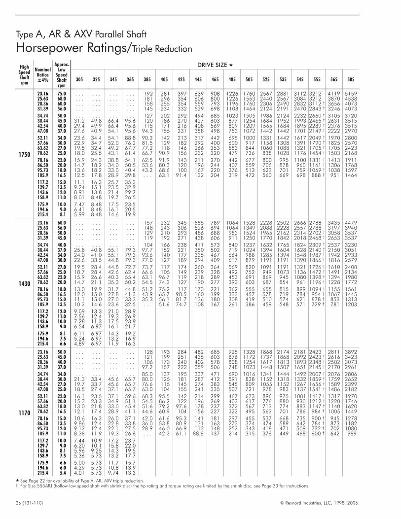
26 (131-110) © Rexnord Industries, LLC, 1998, 2006.
Type A, AR & AXV Parallel Shaft
Horsepower Ratings/Triple Reduction
HighSpeedShaftrpm
NominalRatios±4%
Approx.Low
SpeedShaftrpm
DRIVE SIZE �
305 325 345 365 385 405 425 445 465 485 505 525 535 545 555 565 585
1750
23.16 75.0 . . . . . . . . . . . . 192 281 397 639 908 1226 1760 2567 2881 3112 3212 4119 515925.63 68.0 . . . . . . . . . . . . 181 296 354 606 800 1226 1553 2440 2567 3084 3212 3870 453828.36 60.0 . . . . . . . . . . . . 158 255 354 559 793 1196 1760 2306 2490 2832 3112 † 3656 407331.39 56.0 . . . . . . . . . . . . 145 234 332 529 698 1108 1464 2124 2191 2470 2843 † 3246 4073
34.74 50.0 . . . . . . . . . . . . 127 202 292 494 685 1023 1505 1986 2124 2232 2660 † 3105 372038.44 45.0 31.2 49.8 66.4 95.6 120 186 270 427 603 877 1254 1684 1952 1993 2465 † 2631 351542.54 40.0 29.4 49.9 66.4 95.6 115 171 216 408 569 809 1209 1565 1684 1895 2289 † 2376 351547.08 37.0 27.6 40.9 54.1 95.6 94.3 155 231 358 498 753 1072 1442 1442 1701 2149 † 2222 2970
52.11 34.0 23.6 34.4 54.1 88.8 90.2 142 213 317 442 695 1000 1331 1442 1617 2049 † 1970 280057.66 30.0 22.9 34.7 52.0 76.2 81.5 129 182 292 400 600 917 1158 1308 1391 1790 † 1825 257063.82 27.0 19.5 32.4 49.2 67.7 77.2 118 146 266 353 553 844 1060 1088 1321 1705 † 1705 242370.62 25.0 18.0 25.5 43.1 61.4 66.7 90.9 156 232 320 479 736 838 1028 1176 1454 † 1503 2168
78.16 22.0 15.9 24.3 38.8 54.1 62.5 91.9 143 211 270 442 677 800 995 1100 1331 † 1413 191186.50 20.0 14.7 18.2 34.0 50.5 53.6 80.3 120 196 244 407 559 706 878 960 1161 † 1306 176895.73 18.0 13.6 18.2 33.0 40.4 43.2 68.6 100 167 220 376 513 623 701 759 1069 † 1038 1597105.9 16.5 12.5 17.8 28.9 39.8 . . . 63.1 91.4 132 204 319 472 560 669 698 888 † 951 1464
117.2 15.0 11.1 16.3 25.7 35.3129.7 13.5 9.24 15.1 23.5 32.9143.6 12.0 8.91 13.8 21.4 29.2158.9 11.0 8.01 8.48 19.7 26.5
175.9 10.0 7.47 8.48 17.5 23.5194.6 9.0 6.41 8.48 16.1 20.5215.4 8.1 5.99 8.48 14.6 19.9
1430
23.16 60.0 . . . . . . . . . . . . 157 232 345 555 789 1064 1528 2228 2502 2666 2788 3435 447925.63 56.0 . . . . . . . . . . . . 148 243 306 526 694 1064 1349 2088 2228 2557 2788 3197 394028.36 50.0 . . . . . . . . . . . . 129 210 293 486 688 983 1524 1965 2162 2314 2702 † 3058 353731.39 45.0 . . . . . . . . . . . . 119 192 271 438 606 911 1250 1770 1842 2018 2468 † 2653 3537
34.74 40.0 . . . . . . . . . . . . 104 166 238 411 573 840 1237 1632 1765 1824 2309 † 2537 323038.44 37.0 25.8 40.8 55.1 79.3 97.7 152 221 350 502 719 1024 1394 1604 1628 2140 † 2150 305142.54 34.0 24.0 41.0 55.1 79.3 93.6 140 177 335 467 664 988 1285 1394 1548 1987 † 1942 293347.08 30.0 22.6 33.5 44.8 79.3 77.0 127 189 294 409 617 879 1191 1191 1390 1866 † 1816 2579
52.11 27.0 19.5 28.4 44.8 72.7 73.7 117 174 260 364 569 820 1091 1191 1321 1726 † 1610 240857.66 25.0 18.7 28.4 42.6 62.4 66.6 105 149 239 328 492 752 949 1073 1136 1472 † 1491 213463.82 22.0 15.9 26.6 40.3 55.4 63.1 96.7 119 218 289 453 691 869 945 1080 1398 † 1394 198070.62 20.0 14.7 21.1 35.3 50.2 54.5 74.3 127 190 277 393 603 687 854 961 1196 † 1228 1772
78.16 18.0 13.0 19.9 31.7 44.8 51.2 75.2 117 173 221 362 555 655 815 899 1094 † 1155 156186.50 16.5 12.0 15.0 27.8 41.3 43.9 65.7 98.5 160 199 333 457 578 719 784 954 † 1067 144595.73 15.0 11.1 15.0 27.0 33.3 35.3 56.1 81.7 136 180 308 419 510 574 621 878 † 853 1313105.9 13.5 10.2 14.6 23.6 32.5 . . . 51.6 74.7 108 167 261 386 459 548 571 729 † 781 1203
117.2 12.0 9.09 13.3 21.0 28.9129.7 11.0 7.56 12.4 19.3 26.9143.6 10.0 7.28 11.3 17.5 23.9158.9 9.0 6.54 6.97 16.1 21.7
175.9 8.1 6.11 6.97 14.3 19.2194.6 7.5 5.24 6.97 13.2 16.9215.4 6.6 4.89 6.97 11.9 16.3
1170
23.16 50.0 . . . . . . . . . . . . 128 193 284 482 685 925 1328 1868 2174 2181 2423 2811 389225.63 45.0 . . . . . . . . . . . . 121 199 251 435 603 876 1172 1737 1868 2092 2423 † 2616 342328.36 40.0 . . . . . . . . . . . . 106 173 240 402 578 808 1254 1617 1813 1893 2348 † 2502 307331.39 37.0 . . . . . . . . . . . . 97.2 157 222 359 506 748 1023 1448 1507 1651 2145 † 2170 2961
34.74 34.0 . . . . . . . . . . . . 85.0 137 195 337 471 690 1016 1341 1444 1492 2007 † 2076 280638.44 30.0 21.3 33.4 45.6 65.7 80.0 125 181 287 412 591 838 1152 1318 1332 1859 † 1759 265242.54 27.0 19.7 33.7 45.6 65.7 76.6 115 145 274 383 545 809 1055 1152 1267 1656 † 1589 239947.08 25.0 18.5 27.4 37.1 65.7 63.0 104 155 241 335 507 721 978 983 1137 1541 † 1486 2182
52.11 22.0 16.1 23.5 37.1 59.6 60.3 95.5 142 214 299 467 673 896 975 1081 1417 † 1317 197057.66 20.0 15.3 23.3 34.9 51.1 54.5 86.2 122 196 269 403 617 776 880 930 1212 † 1220 174663.82 18.0 13.0 21.8 33.0 45.4 51.6 79.2 97.6 178 237 372 567 713 774 883 1147 † 1140 162070.62 16.5 12.1 17.4 28.9 41.1 44.6 60.9 104 156 227 322 495 563 701 786 984 † 1005 1449
78.16 15.0 10.6 16.3 26.0 37.1 42.0 61.6 95.3 141 181 297 455 537 668 735 900 † 945 127886.50 13.5 9.86 12.4 22.8 33.8 36.0 53.8 80.9 131 163 273 374 474 589 642 784 † 873 118295.73 12.0 9.12 12.4 22.1 27.5 28.9 46.0 66.9 112 148 252 343 418 471 509 722 † 702 1080105.9 11.0 8.38 11.9 19.3 26.6 . . . 42.2 61.1 88.6 137 214 315 376 449 468 600 † 642 989
117.2 10.0 7.44 10.9 17.2 23.7129.7 9.0 6.20 10.1 15.8 22.0143.6 8.1 5.96 9.25 14.3 19.5158.9 7.5 5.36 5.73 13.2 17.7
175.9 6.6 5.00 5.73 11.7 15.7194.6 6.0 4.29 5.73 10.8 13.9215.4 5.4 4.01 5.73 9.74 13.3
� See Page 22 for availability of Type A, AR, AXV triple reduction.† For Size 555ARJ (hollow low speed shaft with shrink disc) the hp rating and torque rating are limited by the shrink disc, see Page 33 for instructions.
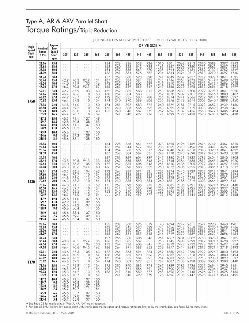
© Rexnord Industries, LLC, 1998, 2006. (131-110) 27
Type A, AR & AXV Parallel Shaft
Torque Ratings/Triple Reduction
(POUND-INCHES AT LOW SPEED SHAFT. . . MULTIPLY VALUES LISTED BY 1000)
HighSpeedShaftrpm
NominalRatios±4%
Approx.Low
SpeedShaftrpm
DRIVE SIZE �
305 325 345 365 385 405 425 445 465 485 505 525 535 545 555 565 585
1750
23.16 75.0 . . . . . . . . . . . . 154 226 336 528 726 1010 1501 2066 2313 2570 2588 3397 434325.63 68.0 . . . . . . . . . . . . 163 260 325 543 738 1163 1467 2206 2350 2772 2863 3657 422428.36 60.0 . . . . . . . . . . . . 154 252 355 561 770 1235 1744 2309 2464 2889 3133 † 3752 434931.39 56.0 . . . . . . . . . . . . 166 261 384 576 782 1234 1644 2324 2517 2813 3210 † 3697 4740
34.74 50.0 . . . . . . . . . . . . 157 252 360 593 820 1241 1849 2407 2637 2789 3392 † 3841 452538.44 45.0 42.9 70.3 92.9 131 167 262 384 584 833 1243 1746 2354 2673 2813 3449 † 3698 463242.54 40.0 44.0 74.9 103 146 173 262 334 603 839 1248 1810 2423 2670 2923 3618 † 3696 504847.08 37.0 46.2 70.5 92.1 157 166 263 389 585 847 1247 1866 2379 2498 2813 3656 † 3718 4999
52.11 34.0 42.7 65.9 103 163 172 262 385 588 815 1253 1868 2433 2700 2922 3795 † 3841 522057.66 30.0 46.4 70.6 110 153 168 264 384 588 851 1252 1870 2407 2701 2851 3616 † 3880 540763.82 27.0 44.9 75.7 113 149 172 263 335 583 788 1256 1874 2441 2566 2959 3914 † 3899 539770.62 25.0 46.4 67.8 110 154 174 240 390 588 806 1255 1876 2178 2674 3003 3640 † 3899 5450
78.16 22.0 44.8 71.0 113 150 174 251 392 583 772 1260 1879 2181 2715 3023 3652 † 3939 545086.50 20.0 46.4 59.2 110 154 175 240 368 586 792 1263 1699 2184 2719 3038 3669 † 3938 546195.73 18.0 45.1 63.0 113 143 153 240 340 587 772 1262 1696 2187 2436 2688 3677 † 3485 5424105.9 16.5 46.4 70.7 110 154 . . . 241 340 497 776 1171 1699 2129 2438 2690 3405 † 3496 5438
117.2 15.0 45.5 71.1 107 149129.7 13.5 42.8 70.8 108 155143.6 12.0 45.6 71.1 107 150158.9 11.0 45.6 50.2 111 155
175.9 10.0 45.6 55.1 107 150194.6 9.0 45.6 59.2 109 141215.4 8.1 45.6 65.1 108 150
1430
23.16 60.0 . . . . . . . . . . . . 154 228 358 561 772 1073 1595 2195 2459 2695 2749 3467 461525.63 56.0 . . . . . . . . . . . . 163 261 344 577 783 1235 1559 2310 2496 2813 3041 3697 448828.36 50.0 . . . . . . . . . . . . 154 254 360 597 817 1242 1848 2408 2618 2888 3329 † 3841 462231.39 45.0 . . . . . . . . . . . . 167 262 384 584 831 1242 1718 2370 2590 2812 3410 † 3698 5038
34.74 40.0 . . . . . . . . . . . . 157 253 359 604 839 1247 1860 2421 2682 2789 3604 † 3840 480838.44 37.0 43.5 70.5 94.3 133 166 262 385 585 848 1247 1745 2384 2688 2812 3665 † 3698 492042.54 34.0 44.0 75.3 105 148 172 262 335 606 843 1254 1810 2435 2705 2922 3844 † 3697 515547.08 30.0 46.3 70.6 93.4 160 166 264 390 588 852 1250 1872 2405 2525 2813 3885 † 3718 5312
52.11 27.0 43.2 66.5 104 163 172 264 384 591 821 1255 1874 2440 2729 2922 3912 † 3841 549457.66 25.0 46.4 70.7 110 154 168 263 385 589 854 1256 1877 2414 2711 2849 3639 † 3879 549463.82 22.0 44.8 76.0 113 149 173 264 334 585 789 1259 1878 2449 2728 2960 3927 † 3901 539770.62 20.0 46.3 68.6 110 154 174 240 388 590 854 1260 1881 2185 2719 3003 3664 † 3899 5451
78.16 18.0 44.8 71.1 113 152 175 252 392 585 773 1263 1885 2185 2721 3023 3674 † 3940 544886.50 16.5 46.3 59.7 110 154 175 241 370 586 790 1265 1700 2188 2725 3036 3689 † 3937 546295.73 15.0 45.1 63.5 113 144 153 240 340 585 773 1265 1695 2191 2441 2691 3696 † 3505 5457105.9 13.5 46.3 71.0 110 154 . . . 241 340 497 777 1173 1701 2135 2444 2693 3421 † 3513 5468
117.2 12.0 45.6 71.0 107 150129.7 11.0 42.9 71.1 109 155143.6 10.0 45.6 71.2 107 150158.9 9.0 45.6 50.4 111 155
175.9 8.1 45.6 55.4 107 150194.6 7.5 45.6 59.6 109 143215.4 6.6 45.6 65.4 107 150
1170
23.16 50.0 . . . . . . . . . . . . 153 232 360 596 819 1140 1694 2249 2611 2694 2920 3468 490125.63 45.0 . . . . . . . . . . . . 163 261 345 583 832 1243 1656 2348 2558 2813 3230 † 3698 476628.36 40.0 . . . . . . . . . . . . 154 256 360 604 839 1248 1859 2422 2683 2888 3536 † 3841 490831.39 37.0 . . . . . . . . . . . . 166 262 384 585 848 1246 1719 2370 2589 2812 3622 † 3696 5154
34.74 34.0 . . . . . . . . . . . . 157 256 360 605 843 1251 1867 2431 2682 2788 3828 † 3841 510538.44 30.0 43.8 70.5 95.4 135 166 263 385 587 851 1253 1745 2408 2699 2812 3891 † 3698 522742.54 27.0 44.1 75.6 106 150 173 264 336 606 845 1258 1812 2443 2732 2923 3915 † 3697 515447.08 25.0 46.4 70.6 94.5 162 166 264 391 589 853 1256 1877 2414 2547 2812 3921 † 3719 5493
52.11 22.0 43.6 67.3 105 163 172 264 383 594 824 1259 1880 2449 2730 2922 3926 † 3840 549357.66 20.0 46.4 70.9 110 154 168 264 385 590 856 1258 1882 2413 2718 2851 3662 † 3880 549463.82 18.0 44.8 76.2 113 149 172 264 335 584 791 1264 1883 2456 2731 2958 3938 † 3899 539770.62 16.5 46.6 69.2 110 154 174 240 389 592 855 1262 1887 2188 2728 3002 3685 † 3900 5448
78.16 15.0 44.7 71.2 113 154 175 252 390 583 774 1267 1889 2189 2726 3021 3694 † 3940 545186.50 13.5 46.5 60.4 111 154 176 241 371 586 791 1267 1700 2193 2728 3039 3706 † 3937 546195.73 12.0 45.3 64.2 113 145 153 241 340 589 777 1265 1696 2194 2448 2696 3714 † 3525 5486105.9 11.0 46.5 70.7 110 154 . . . 241 340 499 779 1175 1696 2138 2447 2698 3441 † 3530 5495
117.2 10.0 45.6 71.1 107 150129.7 9.0 43.0 70.8 109 155143.6 8.1 45.6 71.3 107 150158.9 7.5 45.7 50.7 111 154
175.9 6.6 45.6 55.7 107 150194.6 6.0 45.6 59.8 109 143215.4 5.4 45.7 65.8 107 150
� See Page 22 for availability of Type A, AR, AXV triple reduction.† For Size 555ARJ (hollow low speed shaft with shrink disc) the hp rating and torque rating are limited by the shrink disc, see Page 33 for instructions.
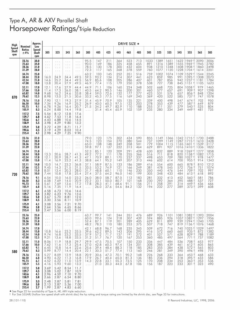
28 (131-110) © Rexnord Industries, LLC, 1998, 2006.
Type A, AR & AXV Parallel Shaft
Horsepower Ratings/Triple Reduction
HighSpeedShaftrpm
NominalRatios±4%
Approx.Low
SpeedShaftrpm
DRIVE SIZE �
305 325 345 365 385 405 425 445 465 485 505 525 535 545 555 565 585
870
23.16 38.0 . . . . . . . . . . . . 95.5 147 211 364 523 713 1033 1389 1651 1622 1969 † 2090 300625.63 34.0 . . . . . . . . . . . . 90.0 149 186 325 458 655 891 1316 1389 1555 1969 † 1945 278228.36 31.0 . . . . . . . . . . . . 78.5 130 178 300 432 604 938 1210 1348 1408 1908 † 1860 249831.39 28.0 . . . . . . . . . . . . 72.3 117 165 268 378 559 760 1077 1120 1228 1704 † 1614 2201
34.74 25.0 . . . . . . . . . . . . 63.2 103 145 252 351 516 759 1002 1074 1109 1529 † 1544 224538.44 22.0 16.0 24.9 34.4 49.5 59.5 93.2 134 214 307 441 623 859 985 991 1395 † 1308 207342.54 21.0 14.6 25.2 34.4 49.5 56.9 85.6 108 205 286 407 601 787 856 942 1237 † 1181 178447.08 18.0 13.8 20.4 27.9 49.5 46.9 77.4 115 179 250 378 538 727 738 845 1151 † 1105 1623
52.11 17.0 12.1 17.6 27.9 44.4 44.9 71.1 106 160 224 348 502 668 725 804 1058 † 979 146557.66 15.0 11.4 17.3 26.0 38.1 40.5 64.2 90.5 146 200 301 460 577 657 691 909 † 907 129863.82 14.0 9.68 16.2 24.6 33.8 38.4 59.0 72.6 132 177 277 423 531 576 657 856 † 848 120470.62 12.5 8.98 13.0 21.5 30.6 33.2 45.3 77.5 116 169 240 369 420 522 585 737 † 747 1078
78.16 11.0 7.90 12.1 19.3 27.9 31.4 45.9 70.9 105 135 221 339 400 498 547 674 † 702 95086.50 10.0 7.34 9.26 16.9 25.2 26.9 40.0 60.3 97.5 122 203 278 353 439 477 587 † 649 87995.73 9.1 6.78 9.26 16.4 20.7 21.5 34.2 49.7 82.9 110 188 255 311 351 379 540 † 525 804105.9 8.3 6.24 8.88 14.4 19.8 . . . 31.4 45.4 65.9 102 159 235 280 334 349 449 † 481 735
117.2 7.5 5.54 8.12 12.8 17.6129.7 6.8 4.62 7.53 11.8 16.4143.6 6.1 4.43 6.88 10.6 14.5158.9 5.5 3.98 4.29 9.80 13.2
175.9 5.0 3.72 4.29 8.71 11.7194.6 4.5 3.19 4.29 8.03 10.4215.4 4.1 2.98 4.29 7.25 9.90
720
23.16 31.0 . . . . . . . . . . . . 79.0 123 175 302 434 590 855 1149 1366 1342 1715 † 1730 248825.63 28.0 . . . . . . . . . . . . 74.5 123 154 270 380 544 737 1099 1149 1287 1715 † 1610 242828.36 25.0 . . . . . . . . . . . . 65.0 108 148 249 358 501 779 1004 1115 1165 1601 † 1539 211731.39 22.0 . . . . . . . . . . . . 59.8 97.1 137 222 313 464 629 891 927 1016 1410 † 1336 1822
34.74 21.0 . . . . . . . . . . . . 52.3 85.1 120 209 291 428 630 832 889 918 1269 † 1277 185838.44 18.0 13.3 20.6 28.7 41.3 49.2 77.2 111 178 255 366 516 711 818 820 1158 † 1082 171542.54 17.0 12.1 20.9 28.7 41.3 47.1 70.9 89.1 170 237 337 498 653 709 780 1027 † 978 147747.08 15.0 11.4 16.9 23.2 41.3 38.8 64.1 95.2 149 207 313 446 602 614 700 955 † 914 1343
52.11 14.0 10.0 14.7 23.2 36.8 37.1 58.9 87.5 133 186 289 416 554 600 665 878 † 810 121257.66 12.5 9.45 14.3 21.5 31.5 33.5 53.2 74.9 121 166 249 381 478 545 572 756 † 751 107463.82 11.0 8.01 13.4 20.3 28.0 31.7 48.8 60.1 110 146 230 350 440 476 544 709 † 702 99770.62 10.0 7.44 10.8 17.8 25.4 27.4 37.5 64.2 96.0 140 199 305 348 433 484 613 † 618 892
78.16 9.1 6.54 10.0 16.0 23.2 26.0 38.0 58.7 87.0 112 183 281 332 413 452 560 † 581 78686.50 8.3 6.08 7.69 14.0 20.9 22.2 33.1 50.0 80.7 101 168 230 292 364 395 488 † 537 72795.73 7.5 5.61 7.69 13.6 17.2 17.8 28.3 41.1 68.6 91.1 156 211 258 291 314 449 † 436 666105.9 6.8 5.16 7.35 11.9 16.4 . . . 26.0 37.6 54.6 84.2 132 194 232 277 289 373 † 399 608
117.2 6.1 4.58 6.73 10.6 14.6129.7 5.5 3.82 6.23 9.76 13.6143.6 5.0 3.67 5.70 8.81 12.0158.9 4.5 3.30 3.56 8.11 10.9
175.9 4.1 3.08 3.56 7.21 9.70194.6 3.8 2.64 3.56 6.65 8.66215.4 3.3 2.47 3.56 6.00 8.19
580
23.16 25.0 . . . . . . . . . . . . 63.7 99.7 141 244 351 476 689 926 1101 1081 1382 † 1393 200425.63 22.0 . . . . . . . . . . . . 60.0 99.6 124 218 307 439 594 885 926 1037 1382 † 1297 195628.36 21.0 . . . . . . . . . . . . 52.4 87.1 119 201 289 405 629 811 899 939 1294 † 1240 170531.39 18.0 . . . . . . . . . . . . 48.2 78.3 110 180 253 375 507 718 747 819 1136 † 1076 1468
34.74 17.0 . . . . . . . . . . . . 42.1 68.8 96.7 168 235 345 509 672 716 740 1025 † 1029 149738.44 15.0 10.8 16.6 23.2 33.5 39.6 62.2 89.5 143 206 295 416 572 660 660 935 † 872 138242.54 14.0 9.74 16.8 23.2 33.5 37.9 57.2 71.7 137 191 272 401 527 571 628 829 † 788 118947.08 12.5 9.21 13.6 18.8 33.5 31.2 51.7 76.7 120 167 253 360 485 497 564 771 † 737 1082
52.11 11.0 8.06 11.9 18.8 29.7 29.9 47.5 70.5 107 150 233 336 447 484 536 708 † 653 97757.66 10.0 7.62 11.6 17.3 25.4 27.0 42.8 60.3 97.4 134 201 308 385 439 461 612 † 605 86563.82 9.1 6.45 10.8 16.4 22.6 25.6 39.4 48.4 88.3 118 185 283 355 384 438 572 † 565 80370.62 8.3 5.99 8.77 14.4 20.4 22.1 30.3 51.7 77.4 113 160 246 281 349 390 496 † 498 719
78.16 7.5 5.27 8.09 12.9 18.8 20.9 30.6 47.3 70.1 90.2 148 226 268 333 364 453 † 468 63386.50 6.8 4.90 6.22 11.3 16.8 17.9 26.7 40.4 65.0 81.3 136 185 236 294 318 395 † 433 58695.73 6.1 4.52 6.22 11.0 13.9 14.3 22.8 33.1 55.3 73.5 125 170 208 234 253 363 † 353 536105.9 5.5 4.16 5.93 9.60 13.2 . . . 21.0 30.3 44.0 67.8 106 156 187 223 233 301 † 323 490
117.2 5.0 3.69 5.42 8.54 11.7129.7 4.5 3.08 5.02 7.87 10.9143.6 4.1 2.96 4.59 7.10 9.70158.9 3.8 2.66 2.87 6.54 8.80
175.9 3.3 2.48 2.87 5.81 7.81194.6 3.0 2.13 2.87 5.36 7.00215.4 2.7 1.99 2.87 4.83 6.60
� See Page 22 for availability of Type A, AR, AXV triple reduction.† For Size 555ARJ (hollow low speed shaft with shrink disc) the hp rating and torque rating are limited by the shrink disc, see Page 33 for instructions.
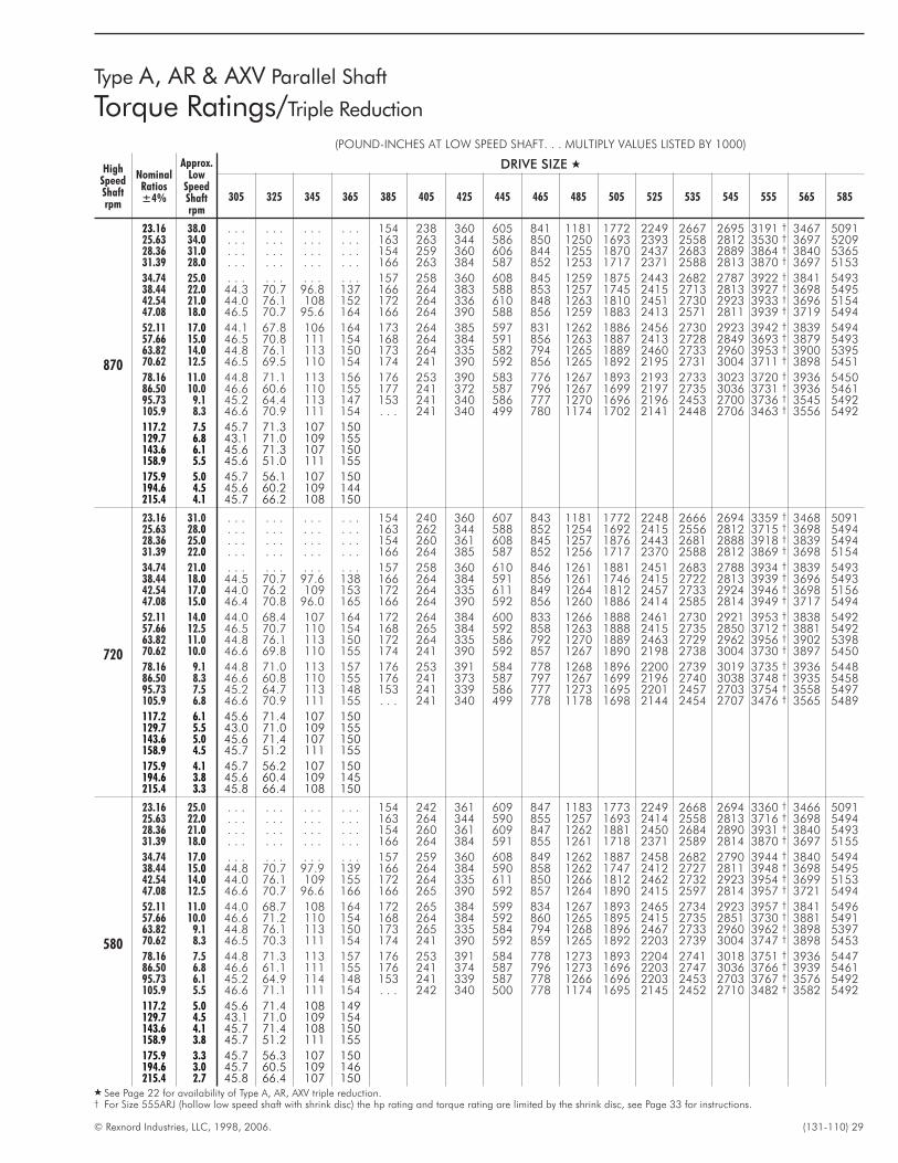
© Rexnord Industries, LLC, 1998, 2006. (131-110) 29
Type A, AR & AXV Parallel Shaft
Torque Ratings/Triple Reduction
(POUND-INCHES AT LOW SPEED SHAFT. . . MULTIPLY VALUES LISTED BY 1000)
HighSpeedShaftrpm
NominalRatios±4%
Approx.Low
SpeedShaftrpm
DRIVE SIZE �
305 325 345 365 385 405 425 445 465 485 505 525 535 545 555 565 585
870
23.16 38.0 . . . . . . . . . . . . 154 238 360 605 841 1181 1772 2249 2667 2695 3191 † 3467 509125.63 34.0 . . . . . . . . . . . . 163 263 344 586 850 1250 1693 2393 2558 2812 3530 † 3697 520928.36 31.0 . . . . . . . . . . . . 154 259 360 606 844 1255 1870 2437 2683 2889 3864 † 3840 536531.39 28.0 . . . . . . . . . . . . 166 263 384 587 852 1253 1717 2371 2588 2813 3870 † 3697 5153
34.74 25.0 . . . . . . . . . . . . 157 258 360 608 845 1259 1875 2443 2682 2787 3922 † 3841 549338.44 22.0 44.3 70.7 96.8 137 166 264 383 588 853 1257 1745 2415 2713 2813 3927 † 3698 549542.54 21.0 44.0 76.1 108 152 172 264 336 610 848 1263 1810 2451 2730 2923 3933 † 3696 515447.08 18.0 46.5 70.7 95.6 164 166 264 390 588 856 1259 1883 2413 2571 2811 3939 † 3719 5494
52.11 17.0 44.1 67.8 106 164 173 264 385 597 831 1262 1886 2456 2730 2923 3942 † 3839 549457.66 15.0 46.5 70.8 111 154 168 264 384 591 856 1263 1887 2413 2728 2849 3693 † 3879 549363.82 14.0 44.8 76.1 113 150 173 264 335 582 794 1265 1889 2460 2733 2960 3953 † 3900 539570.62 12.5 46.5 69.5 110 154 174 241 390 592 856 1265 1892 2195 2731 3004 3711 † 3898 5451
78.16 11.0 44.8 71.1 113 156 176 253 390 583 776 1267 1893 2193 2733 3023 3720 † 3936 545086.50 10.0 46.6 60.6 110 155 177 241 372 587 796 1267 1699 2197 2735 3036 3731 † 3936 546195.73 9.1 45.2 64.4 113 147 153 241 340 586 777 1270 1696 2196 2453 2700 3736 † 3545 5492105.9 8.3 46.6 70.9 111 154 . . . 241 340 499 780 1174 1702 2141 2448 2706 3463 † 3556 5492
117.2 7.5 45.7 71.3 107 150129.7 6.8 43.1 71.0 109 155143.6 6.1 45.6 71.3 107 150158.9 5.5 45.6 51.0 111 155
175.9 5.0 45.7 56.1 107 150194.6 4.5 45.6 60.2 109 144215.4 4.1 45.7 66.2 108 150
720
23.16 31.0 . . . . . . . . . . . . 154 240 360 607 843 1181 1772 2248 2666 2694 3359 † 3468 509125.63 28.0 . . . . . . . . . . . . 163 262 344 588 852 1254 1692 2415 2556 2812 3715 † 3698 549428.36 25.0 . . . . . . . . . . . . 154 260 361 608 845 1257 1876 2443 2681 2888 3918 † 3839 549431.39 22.0 . . . . . . . . . . . . 166 264 385 587 852 1256 1717 2370 2588 2812 3869 † 3698 5154
34.74 21.0 . . . . . . . . . . . . 157 258 360 610 846 1261 1881 2451 2683 2788 3934 † 3839 549338.44 18.0 44.5 70.7 97.6 138 166 264 384 591 856 1261 1746 2415 2722 2813 3939 † 3696 549342.54 17.0 44.0 76.2 109 153 172 264 335 611 849 1264 1812 2457 2733 2924 3946 † 3698 515647.08 15.0 46.4 70.8 96.0 165 166 264 390 592 856 1260 1886 2414 2585 2814 3949 † 3717 5494
52.11 14.0 44.0 68.4 107 164 172 264 384 600 833 1266 1888 2461 2730 2921 3953 † 3838 549257.66 12.5 46.5 70.7 110 154 168 265 384 592 858 1263 1888 2415 2735 2850 3712 † 3881 549263.82 11.0 44.8 76.1 113 150 172 264 335 586 792 1270 1889 2463 2729 2962 3956 † 3902 539870.62 10.0 46.6 69.8 110 155 174 241 390 592 857 1267 1890 2198 2738 3004 3730 † 3897 5450
78.16 9.1 44.8 71.0 113 157 176 253 391 584 778 1268 1896 2200 2739 3019 3735 † 3936 544886.50 8.3 46.6 60.8 110 155 176 241 373 587 797 1267 1699 2196 2740 3038 3748 † 3935 545895.73 7.5 45.2 64.7 113 148 153 241 339 586 777 1273 1695 2201 2457 2703 3754 † 3558 5497105.9 6.8 46.6 70.9 111 155 . . . 241 340 499 778 1178 1698 2144 2454 2707 3476 † 3565 5489
117.2 6.1 45.6 71.4 107 150129.7 5.5 43.0 71.0 109 155143.6 5.0 45.6 71.4 107 150158.9 4.5 45.7 51.2 111 155
175.9 4.1 45.7 56.2 107 150194.6 3.8 45.6 60.4 109 145215.4 3.3 45.8 66.4 108 150
580
23.16 25.0 . . . . . . . . . . . . 154 242 361 609 847 1183 1773 2249 2668 2694 3360 † 3466 509125.63 22.0 . . . . . . . . . . . . 163 264 344 590 855 1257 1693 2414 2558 2813 3716 † 3698 549428.36 21.0 . . . . . . . . . . . . 154 260 361 609 847 1262 1881 2450 2684 2890 3931 † 3840 549331.39 18.0 . . . . . . . . . . . . 166 264 384 591 855 1261 1718 2371 2589 2814 3870 † 3697 5155
34.74 17.0 . . . . . . . . . . . . 157 259 360 608 849 1262 1887 2458 2682 2790 3944 † 3840 549438.44 15.0 44.8 70.7 97.9 139 166 264 384 590 858 1262 1747 2412 2727 2811 3948 † 3698 549542.54 14.0 44.0 76.1 109 155 172 264 335 611 850 1266 1812 2462 2732 2923 3954 † 3699 515347.08 12.5 46.6 70.7 96.6 166 166 265 390 592 857 1264 1890 2415 2597 2814 3957 † 3721 5494
52.11 11.0 44.0 68.7 108 164 172 265 384 599 834 1267 1893 2465 2734 2923 3957 † 3841 549657.66 10.0 46.6 71.2 110 154 168 264 384 592 860 1265 1895 2415 2735 2851 3730 † 3881 549163.82 9.1 44.8 76.1 113 150 173 265 335 584 794 1268 1896 2467 2733 2960 3962 † 3898 539770.62 8.3 46.5 70.3 111 154 174 241 390 592 859 1265 1892 2203 2739 3004 3747 † 3898 5453
78.16 7.5 44.8 71.3 113 157 176 253 391 584 778 1273 1893 2204 2741 3018 3751 † 3936 544786.50 6.8 46.6 61.1 111 155 176 241 374 587 796 1273 1696 2203 2747 3036 3766 † 3939 546195.73 6.1 45.2 64.9 114 148 153 241 339 587 778 1266 1696 2203 2453 2703 3767 † 3576 5492105.9 5.5 46.6 71.1 111 154 . . . 242 340 500 778 1174 1695 2145 2452 2710 3482 † 3582 5492
117.2 5.0 45.6 71.4 108 149129.7 4.5 43.1 71.0 109 154143.6 4.1 45.7 71.4 108 150158.9 3.8 45.7 51.2 111 155
175.9 3.3 45.7 56.3 107 150194.6 3.0 45.7 60.5 109 146215.4 2.7 45.8 66.4 107 150
� See Page 22 for availability of Type A, AR, AXV triple reduction.† For Size 555ARJ (hollow low speed shaft with shrink disc) the hp rating and torque rating are limited by the shrink disc, see Page 33 for instructions.
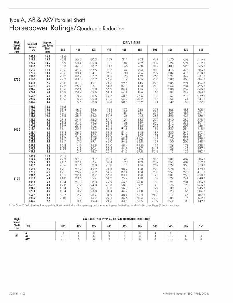
30 (131-110) © Rexnord Industries, LLC, 1998, 2006.
Type A, AR & AXV Parallel Shaft
Horsepower Ratings/Quadruple Reduction
HighSpeedShaftrpm
NominalRatios±5%
Approx.Low Speed
Shaftrpm
DRIVE SIZE
385 405 425 445 465 485 505 525 535 555
1750
105.9 16.5 42.6117.2 15.0 40.8 56.5 80.3 139 211 303 462 570 594 812 †
129.7 13.5 36.9 58.4 85.8 133 184 282 387 524 594 812 †
143.6 12.0 35.3 47.3 78.9 117 166 260 347 483 523 765 †
158.9 11.0 28.6 41.7 67.5 106 147 224 333 416 475 706 †
175.9 10.0 28.6 38.4 54.1 96.5 130 206 299 384 415 610 †
194.6 9.0 23.2 32.9 57.9 84.5 125 179 266 291 377 531 †
215.4 8.1 22.2 30.8 52.9 76.6 112 165 235 289 360 507 †
238.4 7.5 20.0 31.8 45.1 71.6 99.6 145 228 285 291 454 †
263.8 6.6 19.2 25.7 37.1 64.8 87.8 133 210 264 284 395 †
291.9 6.0 15.6 22.4 39.0 56.9 84.1 115 183 208 259 365 †
323.1 5.4 15.5 20.9 35.6 51.4 67.1 106 168 184 247 303 †
357.5 5.0 13.3 18.2 30.5 47.7 60.5 97.6 137 167 218 279 †
395.7 4.4 10.6 16.9 25.0 40.6 54.7 90.2 116 154 174 241 †
437.9 4.0 . . . 15.6 22.8 32.3 50.5 82.9 111 139 153 222 †
1430
105.9 13.5 34.8117.2 12.0 33.4 46.2 65.6 114 172 248 378 466 485 705 †
129.7 11.0 30.1 47.8 70.1 109 151 231 316 429 485 674 †
143.6 10.0 28.8 38.7 64.5 95.9 136 212 283 395 427 626 †
158.9 9.0 23.4 34.1 55.2 87.0 121 183 272 340 389 578 †
175.9 8.1 23.3 31.4 44.2 78.8 106 169 244 314 339 501 †
194.6 7.5 18.9 27.2 47.3 69.1 102 146 218 242 309 436 †
215.4 6.6 18.1 25.1 43.2 62.6 91.8 135 192 237 294 418 †
238.4 6.0 16.4 26.0 36.9 58.5 81.4 118 187 233 242 372 †
263.8 5.4 15.7 21.0 30.3 53.0 71.8 109 171 216 232 324 †
291.9 5.0 12.7 18.3 31.9 46.5 68.8 94.2 149 170 212 299 †
323.1 4.4 12.7 17.0 29.1 42.0 54.8 86.8 137 150 202 248 †
357.5 4.0 10.8 14.9 24.9 39.0 49.4 79.8 112 136 178 228 †
395.7 3.6 8.68 13.8 20.4 33.2 44.7 73.7 94.7 126 142 197 †
437.9 3.2 . . . 12.7 18.7 26.4 41.3 67.8 90.3 113 125 182 †
1170
105.9 11.0 28.5117.2 10.0 27.3 37.8 53.7 93.1 141 203 310 382 402 586 †
129.7 9.0 24.7 39.1 57.4 89.4 123 189 259 351 402 552 †
143.6 8.1 23.6 31.6 52.8 78.6 111 174 232 324 350 513 †
158.9 7.5 19.1 27.9 45.2 71.3 98.7 150 223 278 318 473 †
175.9 6.6 19.1 25.7 36.2 64.5 87.1 138 200 257 278 411 †
194.6 6.0 15.5 22.4 38.7 56.6 83.4 120 178 201 253 358 †
215.4 5.4 14.8 20.6 35.4 51.2 75.2 110 157 194 241 348 †
238.4 5.0 13.4 21.3 30.3 47.9 66.6 96.8 153 191 201 306 †
263.8 4.4 12.8 17.2 24.8 43.3 58.8 89.2 140 176 190 266 †
291.9 4.0 10.4 15.0 26.1 38.0 56.3 77.1 122 139 173 245 †
323.1 3.6 10.4 13.9 23.8 34.4 44.9 71.0 112 123 165 204 †
357.5 3.2 8.87 12.2 20.4 31.9 40.4 65.3 91.8 112 146 187 †
395.7 2.9 7.10 11.3 16.7 27.1 36.6 60.4 77.5 103 116 162 †
437.9 2.7 . . . 10.4 15.3 21.6 33.8 55.5 73.9 92.8 103 149 †
† For Size 555ARJ (hollow low speed shaft with shrink disc) the hp rating and torque rating are limited by the shrink disc, see Page 33 for instructions.
HighSpeedShaftrpm
AVAILABILITY OF TYPES A / AR / AXV QUADRUPLE REDUCTION
TYPE 385 405 425 445 465 485 505 525 535 555
AllA X X X X X X X X . . . . . .AR . . . X X X X X X . . . X XAXV . . . X X X X X X . . . X X
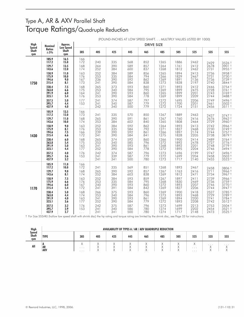
© Rexnord Industries, LLC, 1998, 2006. (131-110) 31
Type A, AR & AXV Parallel Shaft
Torque Ratings/Quadruple Reduction
(POUND-INCHES AT LOW SPEED SHAFT. . . MULTIPLY VALUES LISTED BY 1000)
HighSpeedShaftrpm
NominalRatios±5%
Approx.Low Speed
Shaftrpm
DRIVE SIZE
385 405 425 445 465 485 505 525 535 555
1750
105.9 16.5 166117.2 15.0 172 240 335 568 852 1265 1886 2462 2429 3526 †
129.7 13.5 168 264 390 589 857 1264 1761 2412 2678 3901 †
143.6 12.0 174 252 384 600 837 1268 1812 2462 2731 3955 †
158.9 11.0 163 252 384 589 856 1265 1894 2413 2736 3958 †
175.9 10.0 176 253 335 584 794 1266 1829 2467 2731 3730 †
194.6 9.0 167 236 390 592 862 1269 1891 2136 2736 3739 †
215.4 8.1 173 241 390 584 838 1273 1828 2197 2740 3844 †
238.4 7.5 168 265 373 593 860 1271 1893 2412 2446 3754 †
263.8 6.6 175 253 340 584 795 1269 1899 2475 2728 3761 †
291.9 6.0 164 241 390 593 860 1265 1899 2201 2743 3769 †
323.1 5.4 176 253 390 584 778 1269 1899 2209 2744 3488 †
357.5 5.0 177 241 374 587 797 1272 1695 2206 2749 3496 †
395.7 4.4 153 241 340 587 779 1272 1700 2201 2461 3502 †
437.9 4.0 . . . 242 340 500 779 1272 1724 2151 2456 3511 †
1430
105.9 13.5 166117.2 12.0 173 241 335 570 850 1267 1889 2463 2427 3747 †
129.7 11.0 168 265 390 591 861 1267 1760 2416 2676 3962 †
143.6 10.0 174 253 384 602 840 1265 1808 2464 2729 3960 †
158.9 9.0 163 252 384 592 862 1264 1893 2413 2742 3966 †
175.9 8.1 176 253 335 584 792 1271 1827 2468 2730 3749 †
194.6 7.5 166 239 390 592 861 1266 1897 2174 2744 3757 †
215.4 6.6 172 241 390 584 841 1275 1828 2205 2738 3879 †
238.4 6.0 168 265 374 592 860 1266 1900 2414 2489 3764 †
263.8 5.4 175 253 340 585 796 1272 1892 2478 2727 3776 †
291.9 5.0 163 241 390 593 861 1268 1892 2201 2748 3779 †
323.1 4.4 177 252 390 584 778 1272 1895 2204 2746 3494 †
357.5 4.0 176 242 374 587 796 1273 1696 2199 2747 3496 †
395.7 3.6 153 241 339 587 779 1272 1699 2204 2458 3503 †
437.9 3.2 . . . 241 341 500 780 1273 1717 2140 2455 3523 †
1170
105.9 11.0 166117.2 10.0 172 241 335 569 851 1268 1893 2467 2458 3806 †
129.7 9.0 168 265 390 592 857 1267 1763 2416 2711 3966 †
143.6 8.1 174 252 384 603 838 1269 1812 2471 2734 3967 †
158.9 7.5 163 252 384 593 859 1267 1897 2411 2739 3966 †
175.9 6.6 176 253 335 584 795 1268 1830 2469 2736 3759 †
194.6 6.0 167 240 390 593 860 1272 1893 2207 2746 3770 †
215.4 5.4 172 241 391 584 842 1269 1827 2206 2744 3947 †
238.4 5.0 168 266 375 593 860 1269 1900 2418 2527 3785 †
263.8 4.4 174 253 340 584 796 1273 1893 2468 2729 3789 †
291.9 4.0 163 241 390 593 861 1269 1894 2200 2741 3784 †
323.1 3.6 177 252 390 584 779 1272 1893 2208 2742 3512 †
357.5 3.2 176 242 375 587 796 1273 1699 2213 2753 3504 †
395.7 2.9 153 241 340 586 780 1274 1699 2202 2454 3521 †
437.9 2.7 . . . 241 341 500 780 1274 1717 2148 2473 3525 †
† For Size 555ARJ (hollow low speed shaft with shrink disc) the hp rating and torque rating are limited by the shrink disc, see Page 33 for instructions.
HighSpeedShaftrpm
AVAILABILITY OF TYPES A / AR / AXV QUADRUPLE REDUCTION
TYPE 385 405 425 445 465 485 505 525 535 555
AllA X X X X X X X X . . . . . .AR . . . X X X X X X . . . X XAXV . . . X X X X X X . . . X X
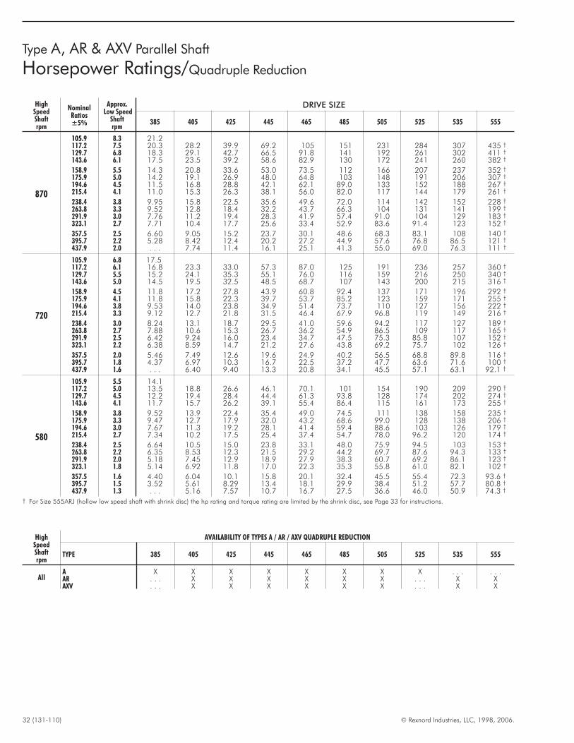
32 (131-110) © Rexnord Industries, LLC, 1998, 2006.
Type A, AR & AXV Parallel Shaft
Horsepower Ratings/Quadruple Reduction
HighSpeedShaftrpm
NominalRatios±5%
Approx.Low Speed
Shaftrpm
DRIVE SIZE
385 405 425 445 465 485 505 525 535 555
870
105.9 8.3 21.2117.2 7.5 20.3 28.2 39.9 69.2 105 151 231 284 307 435 †
129.7 6.8 18.3 29.1 42.7 66.5 91.8 141 192 261 302 411 †
143.6 6.1 17.5 23.5 39.2 58.6 82.9 130 172 241 260 382 †
158.9 5.5 14.3 20.8 33.6 53.0 73.5 112 166 207 237 352 †
175.9 5.0 14.2 19.1 26.9 48.0 64.8 103 148 191 206 307 †
194.6 4.5 11.5 16.8 28.8 42.1 62.1 89.0 133 152 188 267 †
215.4 4.1 11.0 15.3 26.3 38.1 56.0 82.0 117 144 179 261 †
238.4 3.8 9.95 15.8 22.5 35.6 49.6 72.0 114 142 152 228 †
263.8 3.3 9.52 12.8 18.4 32.2 43.7 66.3 104 131 141 199 †
291.9 3.0 7.76 11.2 19.4 28.3 41.9 57.4 91.0 104 129 183 †
323.1 2.7 7.71 10.4 17.7 25.6 33.4 52.9 83.6 91.4 123 152 †
357.5 2.5 6.60 9.05 15.2 23.7 30.1 48.6 68.3 83.1 108 140 †
395.7 2.2 5.28 8.42 12.4 20.2 27.2 44.9 57.6 76.8 86.5 121 †
437.9 2.0 . . . 7.74 11.4 16.1 25.1 41.3 55.0 69.0 76.3 111 †
720
105.9 6.8 17.5117.2 6.1 16.8 23.3 33.0 57.3 87.0 125 191 236 257 360 †
129.7 5.5 15.2 24.1 35.3 55.1 76.0 116 159 216 250 340 †
143.6 5.0 14.5 19.5 32.5 48.5 68.7 107 143 200 215 316 †
158.9 4.5 11.8 17.2 27.8 43.9 60.8 92.4 137 171 196 292 †
175.9 4.1 11.8 15.8 22.3 39.7 53.7 85.2 123 159 171 255 †
194.6 3.8 9.53 14.0 23.8 34.9 51.4 73.7 110 127 156 222 †
215.4 3.3 9.12 12.7 21.8 31.5 46.4 67.9 96.8 119 149 216 †
238.4 3.0 8.24 13.1 18.7 29.5 41.0 59.6 94.2 117 127 189 †
263.8 2.7 7.88 10.6 15.3 26.7 36.2 54.9 86.5 109 117 165 †
291.9 2.5 6.42 9.24 16.0 23.4 34.7 47.5 75.3 85.8 107 152 †
323.1 2.2 6.38 8.59 14.7 21.2 27.6 43.8 69.2 75.7 102 126 †
357.5 2.0 5.46 7.49 12.6 19.6 24.9 40.2 56.5 68.8 89.8 116 †
395.7 1.8 4.37 6.97 10.3 16.7 22.5 37.2 47.7 63.6 71.6 100 †
437.9 1.6 . . . 6.40 9.40 13.3 20.8 34.1 45.5 57.1 63.1 92.1 †
580
105.9 5.5 14.1117.2 5.0 13.5 18.8 26.6 46.1 70.1 101 154 190 209 290 †
129.7 4.5 12.2 19.4 28.4 44.4 61.3 93.8 128 174 202 274 †
143.6 4.1 11.7 15.7 26.2 39.1 55.4 86.4 115 161 173 255 †
158.9 3.8 9.52 13.9 22.4 35.4 49.0 74.5 111 138 158 235 †
175.9 3.3 9.47 12.7 17.9 32.0 43.2 68.6 99.0 128 138 206 †
194.6 3.0 7.67 11.3 19.2 28.1 41.4 59.4 88.6 103 126 179 †
215.4 2.7 7.34 10.2 17.5 25.4 37.4 54.7 78.0 96.2 120 174 †
238.4 2.5 6.64 10.5 15.0 23.8 33.1 48.0 75.9 94.5 103 153 †
263.8 2.2 6.35 8.53 12.3 21.5 29.2 44.2 69.7 87.6 94.3 133 †
291.9 2.0 5.18 7.45 12.9 18.9 27.9 38.3 60.7 69.2 86.1 123 †
323.1 1.8 5.14 6.92 11.8 17.0 22.3 35.3 55.8 61.0 82.1 102 †
357.5 1.6 4.40 6.04 10.1 15.8 20.1 32.4 45.5 55.4 72.3 93.6 †
395.7 1.5 3.52 5.61 8.29 13.4 18.1 29.9 38.4 51.2 57.7 80.8 †
437.9 1.3 . . . 5.16 7.57 10.7 16.7 27.5 36.6 46.0 50.9 74.3 †
† For Size 555ARJ (hollow low speed shaft with shrink disc) the hp rating and torque rating are limited by the shrink disc, see Page 33 for instructions.
HighSpeedShaftrpm
AVAILABILITY OF TYPES A / AR / AXV QUADRUPLE REDUCTION
TYPE 385 405 425 445 465 485 505 525 535 555
AllA X X X X X X X X . . . . . .AR . . . X X X X X X . . . X XAXV . . . X X X X X X . . . X X
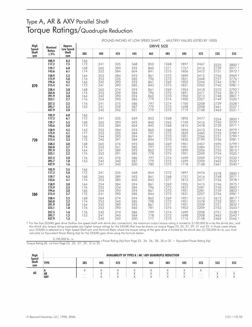
© Rexnord Industries, LLC, 1998, 2006. (131-110) 33
Type A, AR & AXV Parallel Shaft
Torque Ratings/Quadruple Reduction
(POUND-INCHES AT LOW SPEED SHAFT. . . MULTIPLY VALUES LISTED BY 1000)
HighSpeedShaftrpm
NominalRatios±5%
Approx.Low Speed
Shaftrpm
DRIVE SIZE
385 405 425 445 465 485 505 525 535 555
870
105.9 8.3 166117.2 7.5 172 241 335 568 852 1268 1897 2467 2525 3800 †
129.7 6.8 168 265 390 592 860 1271 1757 2416 2739 3971 †
143.6 6.1 174 252 384 604 841 1275 1806 2472 2731 3972 †
158.9 5.5 164 253 384 593 861 1272 1899 2415 2746 3969 †
175.9 5.0 176 253 335 585 796 1273 1821 2468 2727 3776 †
194.6 4.5 166 242 390 593 861 1269 1902 2244 2744 3781 †
215.4 4.1 172 241 390 585 843 1273 1831 2202 2740 3981 †
238.4 3.8 168 265 374 593 861 1269 1904 2418 2570 3792 †
263.8 3.3 174 253 339 584 796 1272 1891 2471 2724 3812 †
291.9 3.0 164 242 390 594 862 1270 1900 2213 2748 3801 †
323.1 2.7 176 254 390 585 779 1274 1900 2207 2749 3520 †
357.5 2.5 176 241 375 586 797 1274 1700 2208 2739 3528 †
395.7 2.2 153 241 339 587 779 1273 1698 2208 2461 3537 †
437.9 2.0 . . . 242 342 501 779 1275 1719 2148 2463 3531 †
720
105.9 6.8 166117.2 6.1 172 241 335 569 853 1268 1895 2477 2554 3800 †
129.7 5.5 168 265 390 593 860 1263 1759 2416 2740 3970 †
143.6 5.0 174 253 384 604 842 1268 1815 2478 2729 3971 †
158.9 4.5 163 253 384 593 860 1268 1894 2410 2744 3979 †
175.9 4.1 177 253 335 584 797 1273 1829 2483 2735 3789 †
194.6 3.8 166 244 390 594 861 1270 1901 2266 2751 3799 †
215.4 3.3 172 242 391 584 844 1273 1830 2199 2756 3981 †
238.4 3.0 168 265 376 593 860 1269 1901 2407 2595 3799 †
263.8 2.7 174 253 341 585 797 1273 1901 2484 2731 3819 †
291.9 2.5 164 241 389 593 862 1270 1899 2206 2755 3815 †
323.1 2.2 176 253 391 585 778 1275 1901 2209 2754 3525 †
357.5 2.0 176 241 376 586 797 1274 1699 2209 2752 3533 †
395.7 1.8 153 242 340 587 779 1275 1699 2209 2462 3532 †
437.9 1.6 . . . 241 340 500 780 1272 1718 2148 2461 3540 †
580
105.9 5.5 166117.2 5.0 172 241 335 568 854 1272 1897 2476 2578 3800 †
129.7 4.5 168 265 389 593 861 1268 1757 2416 2748 3971 †
143.6 4.1 174 253 385 605 843 1271 1812 2477 2726 3978 †
158.9 3.8 164 254 384 594 861 1269 1905 2415 2746 3975 †
175.9 3.3 176 252 334 585 796 1272 1827 2481 2740 3800 †
194.6 3.0 166 244 390 594 861 1270 1901 2281 2759 3803 †
215.4 2.7 172 241 390 585 844 1273 1831 2207 2756 3981 †
238.4 2.5 168 264 374 594 862 1269 1901 2413 2612 3817 †
263.8 2.2 174 253 340 585 798 1272 1901 2478 2733 3821 †
291.9 2.0 164 242 389 595 861 1271 1901 2209 2751 3832 †
323.1 1.8 176 253 390 582 781 1275 1903 2209 2752 3543 †
357.5 1.6 176 242 374 586 799 1274 1699 2208 2751 3538 †
395.7 1.5 153 241 340 584 778 1272 1698 2208 2463 3542 †
437.9 1.3 . . . 242 340 500 777 1273 1715 2148 2465 3546 †
† For the Size 555ARJ gear drive (hollow low speed shaft with shrink disc connection), the maximum output torque rating is limited to 3,100,000 lb-in by the shrink disc, andthis shrink disc torque rating supersedes any higher torque ratings for the 555ARJ that may be shown on torque Pages 23, 25, 27, 29, 31 and 33. In those cases whereyour 555ARJ is selected at a High Speed Shaft rpm and Nominal Ratio where the torque rating of the gear drive is limited by the shrink disc (3,100,000 lb-in), you mustcalculate an Equivalent Power Rating (hp) for the 555ARJ gear drive using the formula below:
3,100,000 lb - in
Torque Rating (lb - in) from Page 23, 25, 27, 29, 31 or 33x Power Rating (hp) from Page 22, 24, 26, 28, 30 or 32 = Equivalent Power Rating (hp)
HighSpeedShaftrpm
AVAILABILITY OF TYPES A / AR / AXV QUADRUPLE REDUCTION
TYPE 385 405 425 445 465 485 505 525 535 555
AllA X X X X X X X X . . . . . .AR . . . X X X X X X . . . X XAXV . . . X X X X X X . . . X X
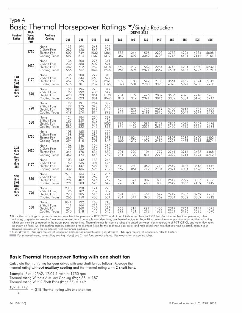
34 (131-110) © Rexnord Industries, LLC, 1998, 2006.
Type A
Basic Thermal Horsepower Ratings �/Single Reduction
NominalRatios
HighSpeedShaftrpm
AuxiliaryCooling
DRIVE SIZE
305 325 345 365 385 405 425 445 465 485 505 525
1.84thru3.05Sizes305thru525
1750
None 131 194 268 3222 Shaft Fans 262 420 563 763Electric Fan 509 749 1032 1384 888 1244 1595 2293 3783 4204 4784 5008 †
Cooling Tubes 597 814 1137 1317 1357 1699 3069 3793 4715 6401 7112 7164 †
1430
None 136 200 275 3412 Shaft Fans 239 380 509 691Electric Fan 482 712 982 1318 862 1217 1582 2254 3743 4204 4850 5232 †
Cooling Tubes 556 757 1064 1246 1254 1594 2871 3569 4504 6137 6927 7191 †
1170
None 136 200 277 3482 Shaft Fans 217 344 463 627Electric Fan 457 675 932 1261 832 1180 1542 2188 3664 4152 4824 5312Cooling Tubes 515 701 989 1166 1168 1501 2700 3398 4320 5927 6783 7230
870
None 133 196 270 3472 Shaft Fans 192 299 405 547Electric Fan 420 623 861 1170 784 1122 1476 2082 3506 4020 4718 5285Cooling Tubes 454 623 881 1047 1018 1317 2371 3016 3859 5334 6190 6717
720
None 129 191 264 3392 Shaft Fans 177 275 373 503Electric Fan 399 592 817 1114 753 1078 1423 2017 3400 3914 4587 5206Cooling Tubes 419 574 814 972 944 1226 2199 2818 3635 5044 5874 6466
580
None 124 184 254 3292 Shaft Fans 163 250 340 459Electric Fan 376 556 770 1052 796 1155 1591 2129 3826 4095 5207 5476Cooling Tubes 380 522 742 891 874 1136 2051 2632 3420 4765 5594 6234
3.38thru5.60Sizes305thru365
3.38thru5.06Sizes385thru525
1750
None 108 150 196 2502 Shaft Fans 198 295 380 534Electric Fan 366 507 675 933 731 1024 1139 1832 2807 3282 3690 4402 †
Cooling Tubes 394 515 701 847 1009 1212 1976 2450 3227 4478 5018 5874 †
1430
None 106 146 194 2502 Shaft Fans 177 262 339 476Electric Fan 344 476 634 880 701 990 1104 1779 2741 3216 3638 4468 †
Cooling Tubes 362 474 648 789 931 1122 1831 2278 3029 4214 4794 5742 †
1170
None 103 142 188 2462 Shaft Fans 159 235 304 426Electric Fan 323 447 597 830 670 950 1069 1713 2649 3137 3545 4442Cooling Tubes 332 436 598 732 869 1051 1712 2134 2871 4004 4596 5637
870
None 97.0 134 178 2362 Shaft Fans 137 200 262 365Electric Fan 294 407 546 762 623 891 1007 1608 2517 2979 3387 4336Cooling Tubes 291 383 525 649 778 915 1488 1883 2542 3556 4109 5149
720
None 93.0 128 171 2282 Shaft Fans 126 182 239 332Electric Fan 278 385 515 721 594 853 966 1542 2412 2886 3269 4231Cooling Tubes 266 350 483 601 734 847 1370 1752 2384 3332 3859 4912
580
None 86.1 122 163 2182 Shaft Fans 111 164 216 300Electric Fan 254 360 483 676 563 811 921 1468 2317 2761 3141 4095Cooling Tubes 240 318 440 546 692 784 1272 1622 2221 3126 3625 4090
� Basic thermal ratings in hp are shown for an ambient temperature of 80°F (27°C) and at an altitude of sea level to 2500 feet. For other ambient temperatures, otheraltitudes, or special air velocity / inlet water temperature / duty cycle considerations, use thermal factors on Page 10 to determine an application adjusted thermal ratingwhich can then be compared to the actual power transmitted. Thermal ratings for cooling tubes are based on water inlet temperature of 70°F (21°C), and water flow ratesas shown on Page 12. For cooling capacity exceeding the methods listed for the gear drive size, ratio, and high speed shaft rpm that you have selected, consult yourRexnord representative for an external heat exchanger package.
† Gear drives at 1750 rpm require jet lubrication and special labyrinth seals; gear drives at 1430 rpm require jet lubrication, refer to Factory.
For screened areas, no auxiliary cooling (None) and 2 shaft fans are not offered. Use electric fan or cooling tubes.
Basic Thermal Horsepower Rating with one shaft fan
Calculate thermal rating for gear drives with one shaft fan as follows: Average thethermal rating without auxiliary cooling and the thermal rating with 2 shaft fans.
Example: Size 425A2, 17.09:1 ratio at 1750 rpmThermal rating Without Auxiliary Cooling (Page 35) = 187Thermal rating With 2 Shaft Fans (Page 35) = 449
1 7 + 4
2= 31 Thermal rating
8 498 with one shaft fan
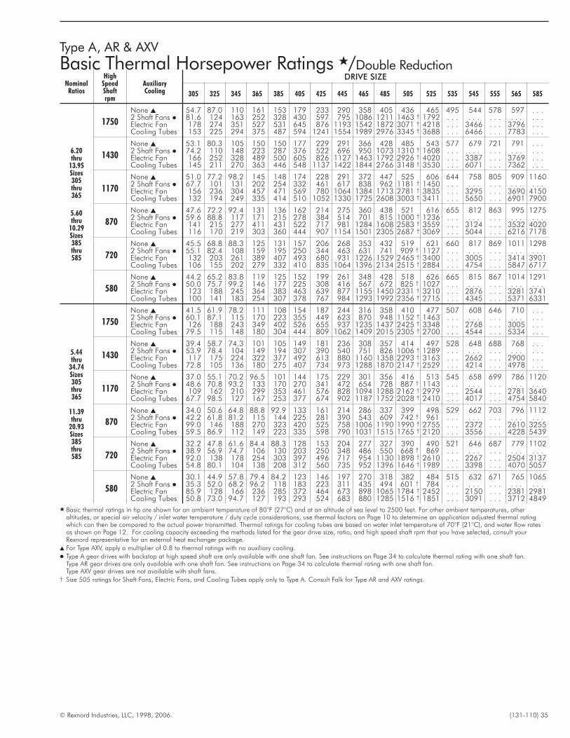
© Rexnord Industries, LLC, 1998, 2006. (131-110) 35
Type A, AR & AXV
Basic Thermal Horsepower Ratings �/Double Reduction
NominalRatios
HighSpeedShaftrpm
AuxiliaryCooling
DRIVE SIZE
305 325 345 365 385 405 425 445 465 485 505 525 535 545 555 565 585
6.20thru
13.95Sizes305thru365
5.60thru
10.29Sizes385thru585
1750
None � 54.7 87.0 110 161 153 179 233 290 358 405 436 465 495 544 578 597 . . .2 Shaft Fans � 81.6 124 163 252 328 430 597 795 1086 1211 1463 † 1792 . . . . . . . . . . . . . . .Electric Fan 178 274 351 527 531 645 876 1193 1542 1872 3071 † 4218 . . . 3466 . . . 3796 . . .Cooling Tubes 153 225 294 375 487 594 1241 1554 1989 2976 3345 † 3688 . . . 6466 . . . 7783 . . .
1430
None � 53.1 80.3 105 150 150 177 229 291 366 428 485 543 577 679 721 791 . . .2 Shaft Fans � 74.2 110 148 223 287 376 522 696 950 1073 1310 † 1608 . . . . . . . . . . . . . . .Electric Fan 166 252 328 489 500 605 826 1127 1463 1792 2926 † 4020 . . . 3387 . . . 3769 . . .Cooling Tubes 145 211 270 363 446 548 1137 1422 1844 2766 3148 † 3530 . . . 6071 . . . 7362 . . .
1170
None � 51.0 77.2 98.2 145 148 174 228 291 372 447 525 606 644 758 805 909 11602 Shaft Fans � 67.7 101 131 202 254 332 461 617 838 962 1181 † 1450 . . . . . . . . . . . . . . .Electric Fan 156 236 304 457 471 569 780 1064 1384 1713 2781 † 3835 . . . 3295 . . . 3690 4150Cooling Tubes 132 194 249 335 414 510 1052 1330 1725 2608 3003 † 3411 . . . 5650 . . . 6901 7900
870
None � 47.6 72.2 92.4 131 136 162 214 275 360 438 521 616 655 812 863 995 12752 Shaft Fans � 59.6 88.8 117 171 215 278 384 514 701 815 1000 † 1236 . . . . . . . . . . . . . . .Electric Fan 141 215 277 411 431 522 717 981 1284 1608 2583 † 3559 . . . 3124 . . . 3532 4020Cooling Tubes 116 170 219 303 360 444 907 1154 1501 2305 2687 † 3069 . . . 5044 . . . 6216 7178
720
None � 45.5 68.8 88.3 125 131 157 206 268 353 432 519 621 660 817 869 1011 12982 Shaft Fans � 55.1 82.4 108 159 195 250 344 463 631 741 909 † 1127 . . . . . . . . . . . . . . .Electric Fan 132 203 261 389 407 493 680 931 1226 1529 2465 † 3400 . . . 3005 . . . 3414 3901Cooling Tubes 106 155 202 279 332 410 835 1064 1396 2134 2515 † 2884 . . . 4754 . . . 5847 6717
580
None � 44.2 65.2 83.8 119 125 152 199 261 348 428 518 626 665 815 867 1014 12912 Shaft Fans � 50.0 75.7 99.2 146 177 225 308 416 567 672 825 † 1027 . . . . . . . . . . . . . . .Electric Fan 123 188 245 364 383 463 639 877 1155 1450 2331 † 3210 . . . 2876 . . . 3281 3741Cooling Tubes 100 141 183 254 307 378 767 984 1293 1992 2356 † 2715 . . . 4345 . . . 5371 6331
5.44thru
34.74Sizes305thru365
11.39thru
20.93Sizes385thru585
1750
None � 41.5 61.9 78.2 111 108 154 187 244 316 358 410 477 507 608 646 710 . . .2 Shaft Fans � 60.1 87.1 115 170 223 355 449 623 870 948 1152 † 1463 . . . . . . . . . . . . . . .Electric Fan 126 188 243 349 402 526 655 937 1235 1437 2425 † 3348 . . . 2768 . . . 3005 . . .Cooling Tubes 79.5 115 148 180 304 444 809 1062 1409 2015 2305 † 2700 . . . 4544 . . . 5334 . . .
1430
None � 39.4 58.7 74.3 101 105 149 181 236 308 357 414 497 528 648 688 768 . . .2 Shaft Fans � 53.9 78.4 104 149 194 307 390 540 751 826 1006 † 1289 . . . . . . . . . . . . . . .Electric Fan 117 175 224 322 377 492 613 880 1160 1358 2293 † 3163 . . . 2662 . . . 2900 . . .Cooling Tubes 72.8 105 136 180 275 407 734 973 1288 1870 2147 † 2529 . . . 4214 . . . 4978 . . .
1170
None � 37.0 55.1 70.2 96.5 101 144 175 229 301 356 416 513 545 658 699 786 11202 Shaft Fans � 48.6 70.8 93.2 133 170 270 341 472 654 728 887 † 1143 . . . . . . . . . . . . . . .Electric Fan 109 162 210 299 353 461 576 828 1094 1288 2162 † 2979 . . . 2544 . . . 2781 3640Cooling Tubes 67.7 98.5 127 167 253 377 674 902 1187 1752 2028 † 2410 . . . 4017 . . . 4754 5840
870
None � 34.0 50.6 64.8 88.8 92.9 133 161 214 286 337 399 498 529 662 703 796 11122 Shaft Fans � 42.2 61.8 81.2 115 144 225 281 390 543 609 742 † 961 . . . . . . . . . . . . . . .Electric Fan 99.0 146 188 270 323 420 525 758 1006 1190 1990 † 2755 . . . 2372 . . . 2610 3255Cooling Tubes 59.5 86.9 112 149 223 335 598 790 1031 1515 1765 † 2120 . . . 3556 . . . 4228 5439
720
None � 32.2 47.8 61.6 84.4 88.3 128 153 204 277 327 390 490 521 646 687 779 11022 Shaft Fans � 38.9 56.9 74.7 106 130 203 250 348 486 550 668 † 869 . . . . . . . . . . . . . . .Electric Fan 92.0 138 178 254 303 397 496 717 954 1130 1898 † 2610 . . . 2267 . . . 2504 3137Cooling Tubes 54.8 80.1 104 138 208 312 560 735 952 1396 1646 † 1989 . . . 3398 . . . 4070 5057
580
None � 30.1 44.9 57.8 79.4 84.2 123 146 197 270 318 382 484 515 632 671 765 10652 Shaft Fans � 35.3 52.0 68.2 96.2 118 183 223 311 435 494 601 † 784 . . . . . . . . . . . . . . .Electric Fan 85.9 128 166 236 285 372 464 673 898 1065 1784 † 2452 . . . 2150 . . . 2381 2981Cooling Tubes 50.8 73.0 94.7 127 193 293 524 683 880 1285 1516 † 1851 . . . 3091 . . . 3712 4849
� Basic thermal ratings in hp are shown for an ambient temperature of 80°F (27°C) and at an altitude of sea level to 2500 feet. For other ambient temperatures, otheraltitudes, or special air velocity / inlet water temperature / duty cycle considerations, use thermal factors on Page 10 to determine an application adjusted thermal ratingwhich can then be compared to the actual power transmitted. Thermal ratings for cooling tubes are based on water inlet temperature of 70°F (21°C), and water flow ratesas shown on Page 12. For cooling capacity exceeding the methods listed for the gear drive size, ratio, and high speed shaft rpm that you have selected, consult yourRexnord representative for an external heat exchanger package.
� For Type AXV, apply a multiplier of 0.8 to thermal ratings with no auxiliary cooling.
� Type A gear drives with backstop at high speed shaft are only available with one shaft fan. See instructions on Page 34 to calculate thermal rating with one shaft fan.Type AR gear drives are only available with one shaft fan. See instructions on Page 34 to calculate thermal rating with one shaft fan.Type AXV gear drives are not available with shaft fans.
† Size 505 ratings for Shaft Fans, Electric Fans, and Cooling Tubes apply only to Type A. Consult Falk for Type AR and AXV ratings.

36 (131-110) © Rexnord Industries, LLC, 1998, 2006.
Type A, AR & AXV
Basic Thermal Horsepower Ratings �/Triple Reduction
NominalRatios
HighSpeedShaftrpm
AuxiliaryCooling
DRIVE SIZE
305 325 345 365 385 405 425 445 465 485 505 525 535 545 555 565 585
38.44thru
86.50Sizes305thru365
23.16thru
47.08Sizes385thru585
1750
None � 26.2 37.7 49.3 67.0 89.4 109 134 177 231 286 345 415 442 540 574 623 8382 Shaft Fans � . . . . . . . . . . . . 133 177 214 298 414 554 672 † 812 . . . 1318 . . . 1503 1885Electric Fan 78.9 114 152 208 275 347 452 631 837 1075 1977 † 2399 . . . 1964 . . . 2175 2451Cooling Tubes . . . . . . . . . . . . 242 303 558 728 951 1475 1699 † 1976 . . . 3767 . . . 4675 5387
1430
None � 24.8 35.6 46.9 63.0 83.2 100 126 166 220 279 340 410 436 546 580 651 8632 Shaft Fans � . . . . . . . . . . . . 118 156 190 264 365 492 597 † 726 . . . 1169 . . . 1344 1700Electric Fan 73.0 106 141 192 256 323 418 584 784 1011 1858 † 2254 . . . 1872 . . . 2082 2359Cooling Tubes . . . . . . . . . . . . 227 286 523 682 890 1343 1567 † 1831 . . . 3477 . . . 4359 5044
1170
None � 23.3 33.5 44.4 59.2 78.3 93.3 120 159 211 274 335 405 431 542 576 659 8692 Shaft Fans � . . . . . . . . . . . . 106 137 170 236 327 442 535 † 656 . . . 1041 . . . 1217 1542Electric Fan 67.7 98.2 131 179 237 302 393 550 730 952 1740 † 2122 . . . 1779 . . . 1990 2267Cooling Tubes . . . . . . . . . . . . 215 271 494 644 842 1246 1462 † 1712 . . . 3200 . . . 4043 4689
870
None � 21.2 30.7 40.7 54.0 71.8 86.9 109 145 194 249 307 378 402 507 539 650 8512 Shaft Fans � . . . . . . . . . . . . 91.6 118 146 202 278 372 453 † 561 . . . 871 . . . 1054 1344Electric Fan 61.0 88.0 118 161 216 273 353 501 667 866 1582 † 1924 . . . 1634 . . . 1858 2122Cooling Tubes . . . . . . . . . . . . 184 234 439 572 749 1144 1330 † 1528 . . . 2950 . . . 3582 4188
720
None � 20.0 28.9 38.4 50.5 68.7 83.7 105 138 185 236 294 364 388 497 529 625 8172 Shaft Fans � . . . . . . . . . . . . 84.6 109 134 185 254 336 414 † 513 . . . 795 . . . 954 1217Electric Fan 56.8 82.8 110 150 203 257 333 468 623 820 1489 † 1832 . . . 1555 . . . 1766 2017Cooling Tubes . . . . . . . . . . . . 170 216 410 536 703 1100 1256 † 1 436 . . . 2726 . . . 3424 4030
580
None � 18.7 27.0 36.0 47.3 65.6 80.7 100 132 177 225 281 352 374 481 511 608 7932 Shaft Fans � . . . . . . . . . . . . 78.1 100 123 168 231 304 376 † 468 . . . 718 . . . 869 1112Electric Fan 52.8 76.9 103 139 190 241 314 440 586 763 1390 † 1717 . . . 1475 . . . 1676 1921Cooling Tubes . . . . . . . . . . . . 155 198 383 502 660 1050 1193 † 1350 . . . 2472 . . . 3123 3689
95.73thru
215.4Sizes305thru365
52.11thru
105.9Sizes385thru585
1750
None � 20.6 28.3 38.0 50.3 67.0 80.5 106 138 186 223 274 349 371 476 505 560 7392 Shaft Fans � . . . . . . . . . . . . 100 131 166 228 323 415 511 † 645 . . . 1085 . . . 1243 1542Electric Fan 60.4 83.0 113 154 212 269 347 503 654 847 1503 † 1858 . . . 1595 . . . 1766 1977Cooling Tubes . . . . . . . . . . . . 180 223 408 531 698 1038 1193 † 1383 . . . 2779 . . . 3516 3951
1430
None � 19.2 26.5 35.7 47.2 63.5 76.4 98.2 130 174 214 262 327 347 443 471 560 7312 Shaft Fans � . . . . . . . . . . . . 89.4 117 146 202 283 366 449 † 561 . . . 929 . . . 1104 1371Electric Fan 55.8 76.7 105 142 198 250 319 464 608 793 1410 † 1727 . . . 1476 . . . 1674 1872Cooling Tubes . . . . . . . . . . . . 163 204 387 498 655 946 1112 † 1317 . . . 2660 . . . 3253 3674
1170
None � 17.9 24.6 33.2 43.9 60.8 73.1 92.0 122 163 206 253 308 328 435 462 540 7012 Shaft Fans � . . . . . . . . . . . . 80.9 105 131 179 252 327 399 † 494 . . . 825 . . . 975 1217Electric Fan 51.5 70.9 97.0 131 185 233 299 435 564 742 1315 † 1608 . . . 1397 . . . 1582 1766Cooling Tubes . . . . . . . . . . . . 148 190 369 470 620 872 1047 † 1264 . . . 2436 . . . 3095 3516
870
None � 16.2 22.3 30.3 39.9 55.1 67.2 84.6 112 150 188 231 286 303 401 426 523 6732 Shaft Fans � . . . . . . . . . . . . 69.7 90.4 113 154 215 275 339 † 420 . . . 684 . . . 838 1046Electric Fan 46.1 63.5 87.1 118 166 212 270 395 514 671 1189 † 1463 . . . 1275 . . . 1463 1648Cooling Tubes . . . . . . . . . . . . 127 165 313 403 533 774 932 † 1123 . . . 2265 . . . 2739 3121
720
None � 15.3 20.8 28.5 37.2 52.2 64.3 81.1 108 145 179 220 274 292 391 416 498 6392 Shaft Fans � . . . . . . . . . . . . 64.1 83.0 103 141 196 249 308 † 384 . . . 622 . . . 754 945Electric Fan 43.1 59.3 81.5 110 156 199 254 373 484 634 1122 † 1384 . . . 1213 . . . 1384 1555Cooling Tubes . . . . . . . . . . . . 117 150 286 369 490 726 874 † 1054 . . . 2081 . . . 2621 3016
580
None � 14.2 19.5 26.6 34.7 49.5 61.6 77.6 103 139 171 210 264 281 378 401 481 6162 Shaft Fans � . . . . . . . . . . . . 58.9 76.1 95.1 130 180 226 280 † 349 . . . 561 . . . 684 859Electric Fan 39.9 55.1 75.6 102 146 186 239 348 453 593 1049 † 1295 . . . 1145 . . . 1312 1474Cooling Tubes . . . . . . . . . . . . 107 138 260 337 449 680 820 † 988 . . . 1881 . . . 2385 2747
� Basic thermal ratings in hp are shown for an ambient temperature of 80°F (27°C) and at an altitude of sea level to 2500 feet. For other ambient temperatures, otheraltitudes, or special air velocity / inlet water temperature / duty cycle considerations, use thermal factors on Page 10 to determine an application adjusted thermal ratingwhich can then be compared to the actual power transmitted. Thermal ratings for cooling tubes are based on water inlet temperature of 70°F (21°C), and water flow ratesas shown on Page 12. For cooling capacity exceeding the methods listed for the gear drive size, ratio, and high speed shaft rpm that you have selected, consult yourRexnord representative for an external heat exchanger package.
� For Type AXV, apply a multiplier of 0.8 to thermal ratings with no auxiliary cooling.
� Type A gear drives with backstop at high speed shaft are only available with one shaft fan. See instructions on Page 34 to calculate thermal rating with one shaft fan.Type AR gear drives are only available with one shaft fan. See instructions on Page 34 to calculate thermal rating with one shaft fan.Type AXV gear drives are not available with shaft fans.
† Size 505 ratings for Shaft Fans, Electric Fans, and Cooling Tubes apply only to Type A. Consult Falk for Type AR and AXV ratings.
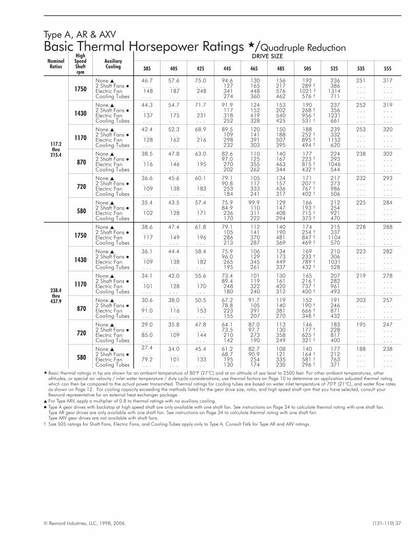
© Rexnord Industries, LLC, 1998, 2006. (131-110) 37
Type A, AR & AXV
Basic Thermal Horsepower Ratings �/Quadruple Reduction
NominalRatios
HighSpeedShaftrpm
AuxiliaryCooling
DRIVE SIZE
385 405 425 445 465 485 505 525 535 555
117.2thru
215.4
1750
None � 46.7 57.6 75.0 94.6 130 156 192 236 251 3172 Shaft Fans � . . . . . . . . . 127 165 217 289 † 386 . . . . . .Electric Fan 148 187 248 341 448 576 1021 † 1314 . . . . . .Cooling Tubes . . . . . . . . . 274 360 462 576 † 711 . . . . . .
1430
None � 44.3 54.7 71.7 91.9 124 153 190 237 252 3192 Shaft Fans � . . . . . . . . . 117 152 202 268 † 356 . . . . . .Electric Fan 137 175 231 318 419 540 956 † 1231 . . . . . .Cooling Tubes . . . . . . . . . 252 328 425 531 † 661 . . . . . .
1170
None � 42.4 52.3 68.9 89.5 120 150 188 239 253 3202 Shaft Fans � . . . . . . . . . 109 141 188 252 † 332 . . . . . .Electric Fan 128 162 216 298 391 507 895 † 1152 . . . . . .Cooling Tubes . . . . . . . . . 232 303 395 494 † 620 . . . . . .
870
None � 38.5 47.8 63.0 82.6 110 140 177 224 238 3022 Shaft Fans � . . . . . . . . . 97.0 125 167 223 † 293 . . . . . .Electric Fan 116 146 195 270 355 463 815 † 1046 . . . . . .Cooling Tubes . . . . . . . . . 202 262 344 432 † 544 . . . . . .
720
None � 36.6 45.6 60.1 79.1 105 134 171 217 232 2932 Shaft Fans � . . . . . . . . . 90.8 117 157 207 † 273 . . . . . .Electric Fan 109 138 183 253 333 436 767 † 986 . . . . . .Cooling Tubes . . . . . . . . . 184 241 317 402 † 506 . . . . . .
580
None � 35.4 43.5 57.4 75.9 99.9 129 166 212 225 2842 Shaft Fans � . . . . . . . . . 84.9 110 147 193 † 254 . . . . . .Electric Fan 102 128 171 236 311 408 715 † 921 . . . . . .Cooling Tubes . . . . . . . . . 170 222 294 373 † 470 . . . . . .
238.4thru
437.9
1750
None � 38.6 47.4 61.8 79.1 112 140 174 215 228 2882 Shaft Fans � . . . . . . . . . 105 141 190 254 † 337 . . . . . .Electric Fan 117 149 196 286 370 481 847 † 1104 . . . . . .Cooling Tubes . . . . . . . . . 213 287 369 469 † 570 . . . . . .
1430
None � 36.1 44.4 58.4 75.9 106 134 169 210 223 2822 Shaft Fans � . . . . . . . . . 96.0 129 173 233 † 306 . . . . . .Electric Fan 109 138 182 265 345 449 789 † 1031 . . . . . .Cooling Tubes . . . . . . . . . 195 261 337 432 † 528 . . . . . .
1170
None � 34.1 42.0 55.6 73.4 101 130 165 207 219 2782 Shaft Fans � . . . . . . . . . 89.4 119 161 216 † 282 . . . . . .Electric Fan 101 128 170 248 322 420 737 † 961 . . . . . .Cooling Tubes . . . . . . . . . 180 240 312 400 † 493 . . . . . .
870
None � 30.6 38.0 50.5 67.2 91.7 119 152 191 203 2572 Shaft Fans � . . . . . . . . . 78.8 105 140 190 † 246 . . . . . .Electric Fan 91.0 116 153 223 291 381 666 † 871 . . . . . .Cooling Tubes . . . . . . . . . 155 207 270 348 † 432 . . . . . .
720
None � 29.0 35.8 47.8 64.1 87.0 113 146 183 195 2472 Shaft Fans � . . . . . . . . . 73.5 97.7 130 177 † 228 . . . . . .Electric Fan 85.0 109 144 210 273 358 625 † 817 . . . . . .Cooling Tubes . . . . . . . . . 142 190 249 321 † 400 . . . . . .
580
None � 27.4 34.0 45.4 61.2 82.7 108 140 177 188 2382 Shaft Fans � . . . . . . . . . 68.7 90.9 121 164 † 212 . . . . . .Electric Fan 79.2 101 133 195 254 335 581 † 763 . . . . . .Cooling Tubes . . . . . . . . . 130 174 230 296 † 371 . . . . . .
� Basic thermal ratings in hp are shown for an ambient temperature of 80°F (27°C) and at an altitude of sea level to 2500 feet. For other ambient temperatures, otheraltitudes, or special air velocity / inlet water temperature / duty cycle considerations, use thermal factors on Page 10 to determine an application adjusted thermal ratingwhich can then be compared to the actual power transmitted. Thermal ratings for cooling tubes are based on water inlet temperature of 70°F (21°C), and water flow ratesas shown on Page 12. For cooling capacity exceeding the methods listed for the gear drive size, ratio, and high speed shaft rpm that you have selected, consult yourRexnord representative for an external heat exchanger package.
� For Type AXV, apply a multiplier of 0.8 to thermal ratings with no auxiliary cooling.
� Type A gear drives with backstop at high speed shaft are only available with one shaft fan. See instructions on Page 34 to calculate thermal rating with one shaft fan.Type AR gear drives are only available with one shaft fan. See instructions on Page 34 to calculate thermal rating with one shaft fan.Type AXV gear drives are not available with shaft fans.
† Size 505 ratings for Shaft Fans, Electric Fans, and Cooling Tubes apply only to Type A. Consult Falk for Type AR and AXV ratings.
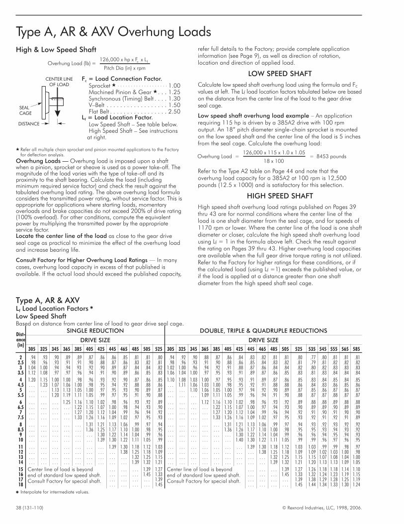
38 (131-110) © Rexnord Industries, LLC, 1998, 2006.
Type A, AR & AXV Overhung LoadsHigh & Low Speed Shaft
Overhung Load (lb) =126,000 x hp x F x L
Pitch D
c f
ia (in) x rpm
Fc = Load Connection Factor.Sprocket � . . . . . . . . . . . . . . . . . . . 1.00Machined Pinion & Gear � . . . 1.25Synchronous (Timing) Belt . . . . 1.30V–Belt . . . . . . . . . . . . . . . . . . 1.50Flat Belt . . . . . . . . . . . . . . . . . 2.50
Lf = Load Location Factor.Low Speed Shaft – See table below.High Speed Shaft – See instructions
at right.
� Refer all multiple chain sprocket and pinion mounted applications to the Factoryfor deflection analysis.
Overhung Loads — Overhung load is imposed upon a shaftwhen a pinion, sprocket or sheave is used as a power take-off. Themagnitude of the load varies with the type of take-off and itsproximity to the shaft bearing. Calculate the load (includingminimum required service factor) and check the result against thetabulated overhung load rating. The above overhung load formulaconsiders the transmitted power rating, without service factor. This isappropriate for applications where starting loads, momentaryoverloads and brake capacities do not exceed 200% of drive rating(100% overload). For other conditions, compute the equivalentpower by multiplying the transmitted power by the appropriateservice factor.Locate the center line of the load as close to the gear driveseal cage as practical to minimize the effect of the overhung loadand increase bearing life.
Consult Factory for Higher Overhung Load Ratings — In manycases, overhung load capacity in excess of that published isavailable. If the actual load should exceed the published capacity,
refer full details to the Factory; provide complete applicationinformation (see Page 9), as well as direction of rotation,location and direction of applied load.
LOW SPEED SHAFT
Calculate low speed shaft overhung load using the formula and Fc
values at left. The Lf load location factors tabulated below are basedon the distance from the center line of the load to the gear driveseal cage.
Low speed shaft overhung load example – An applicationrequiring 115 hp is driven by a 385A2 drive with 100 rpmoutput. An 18” pitch diameter single-chain sprocket is mountedon the low speed shaft and the center line of the load is 5 inchesfrom the seal cage. Calculate the overhung load:
Overhung Load =126,000 x 115 x 1.0 x 1.05
18 x 100= 8453 pounds
Refer to the Type A2 table on Page 44 and note that theoverhung load capacity for a 385A2 at 100 rpm is 12,500pounds (12.5 x 1000) and is satisfactory for this selection.
HIGH SPEED SHAFT
High speed shaft overhung load ratings published on Pages 39thru 43 are for normal conditions where the center line of theload is one shaft diameter from the seal cage, and for speeds of1170 rpm or lower. Where the center line of the load is one shaftdiameter or closer, calculate the high speed shaft overhung loadusing Lf = 1 in the formula above left. Check the result againstthe rating on Pages 39 thru 43. Higher overhung load capacitiesare available when the full gear drive torque rating is not utilized.Refer to the Factory for higher ratings for these conditions, or ifthe calculated load (using Lf =1) exceeds the published value, orif the load is applied at a distance greater than one shaftdiameter from the high speed shaft seal cage.
DISTANCE
CENTER LINEOF LOAD
SEALCAGE
Type A, AR & AXVLf Load Location Factors �
Low Speed ShaftBased on distance from center line of load to gear drive seal cage.
Dist-ance(in)
SINGLE REDUCTION DOUBLE, TRIPLE & QUADRUPLE REDUCTIONS
DRIVE SIZE DRIVE SIZE
305 325 345 365 385 405 425 445 465 485 505 525 305 325 345 365 385 405 425 445 465 485 505 525 535 545 555 565 585
2 .94 .93 .90 .89 .89 .87 .86 .86 .85 .81 .81 .80 .94 .92 .90 .88 .87 .86 .84 .83 .82 .81 .81 .80 .77 .80 .81 .81 .812.5 .98 .96 .93 .91 .91 .90 .88 .87 .86 .83 .82 .81 .98 .96 .93 .91 .90 .88 .86 .85 .84 .83 .82 .81 .79 .81 .82 .82 .823 1.04 1.00 .94 .94 93 .92 .90 .89 .87 .84 .84 .82 1.02 1.00 .96 .94 .92 .91 .88 .87 .86 .84 .84 .82 .80 .82 .83 .83 .83
3.5 1.12 1.08 .97 .97 .96 .94 .91 .90 .89 .86 .85 .83 1.06 1.04 1.00 .97 .95 .93 .91 .89 .87 .86 .85 .83 .81 .83 .84 .84 .84
4 1.20 1.15 1.00 1.00 .98 .96 .93 .92 .90 .87 .86 .85 1.10 1.08 1.03 1.00 .97 .95 .93 .91 .89 .87 .86 .85 .83 .84 .85 .84 .854.5 . . . 1.23 1.07 1.06 1.00 .98 .95 .94 .92 .88 .88 .86 . . . 1.11 1.06 1.03 1.00 .98 .95 .92 .91 .88 .88 .86 .84 .83 .86 .85 .865 . . . . . . 1.13 1.13 1.05 1.00 .97 .95 .93 .90 .89 .87 . . . . . . 1.10 1.06 1.05 1.00 .97 .94 .92 .90 .89 .87 .85 .86 .87 .86 .87
5.5 . . . . . . 1.20 1.19 1.11 1.05 .99 .97 .95 .91 .90 .88 . . . . . . . . . 1.09 1.11 1.05 .99 .96 .94 .91 .90 .88 .87 .87 .88 .87 .87
6 . . . . . . . . . 1.25 1.16 1.10 1.02 .98 .96 .93 .92 .89 . . . . . . . . . 1.12 1.16 1.10 1.02 .98 .96 .93 .92 .89 .88 .88 .89 .88 .886.5 . . . . . . . . . . . . 1.22 1.15 1.07 1.00 .98 .94 .93 .90 . . . . . . . . . . . . 1.22 1.15 1.07 1.00 .97 .94 .93 .90 .89 .89 .90 .89 .897 . . . . . . . . . . . . 1.27 1.20 1.12 1.04 .99 .96 .94 .92 . . . . . . . . . . . . 1.27 1.20 1.12 1.04 .99 .96 .94 .92 .91 .90 .91 .90 .90
7.5 . . . . . . . . . . . . 1.33 1.26 1.16 1.09 1.02 .97 .95 .93 . . . . . . . . . . . . 1.33 1.26 1.16 1.09 1.02 .97 .95 .93 .92 .91 .92 .91 .89
8 . . . . . . . . . . . . . . . 1.31 1.21 1.13 1.06 .99 .97 .94 . . . . . . . . . . . . . . . 1.31 1.21 1.13 1.06 .99 .97 .94 .93 .92 .93 .92 .928.5 . . . . . . . . . . . . . . . 1.36 1.25 1.17 1.10 1.00 .98 .95 . . . . . . . . . . . . . . . 1.36 1.26 1.17 1.10 1.00 .98 .95 .95 .93 .94 .93 .929 . . . . . . . . . . . . . . . . . . 1.30 1.22 1.14 1.04 .99 .96 . . . . . . . . . . . . . . . . . . 1.30 1.22 1.14 1.04 .99 .96 .96 .94 .95 .94 .93
10 . . . . . . . . . . . . . . . . . . 1.39 1.30 1.22 1.11 1.05 .99 . . . . . . . . . . . . . . . . . . 1.40 1.30 1.22 1.11 1.05 .99 .99 .96 .97 .96 .95
11 . . . . . . . . . . . . . . . . . . . . . 1.39 1.30 1.18 1.12 1.03 . . . . . . . . . . . . . . . . . . . . . 1.39 1.30 1.18 1.12 1.03 1.03 .99 .99 .98 .9712 . . . . . . . . . . . . . . . . . . . . . . . . 1.38 1.25 1.18 1.09 . . . . . . . . . . . . . . . . . . . . . . . . 1.38 1.25 1.18 1.09 1.09 1.02 1.03 1.00 .9813 . . . . . . . . . . . . . . . . . . . . . . . . . . . 1.32 1.25 1.15 . . . . . . . . . . . . . . . . . . . . . . . . . . . 1.32 1.25 1.15 1.15 1.07 1.08 1.04 1.0014 . . . . . . . . . . . . . . . . . . . . . . . . . . . 1.39 1.32 1.21 . . . . . . . . . . . . . . . . . . . . . . . . . . . 1.39 1.32 1.21 1.20 1.13 1.13 1.09 1.05
15 Center line of load is beyondend of standard low speed shaft.Consult Factory for special shaft.
. . . . . . . . . 1.39 1.27 Center line of load is beyondend of standard low speed shaft.Consult Factory for special shaft.
. . . . . . . . . 1.39 1.27 1.26 1.18 1.18 1.14 1.1016 . . . . . . . . . 1.45 1.33 . . . . . . . . . 1.45 1.33 1.32 1.24 1.23 1.19 1.1517 . . . . . . . . . . . . 1.39 . . . . . . . . . . . . 1.39 1.38 1.29 1.28 1.25 1.1918 . . . . . . . . . . . . 1.45 . . . . . . . . . . . . 1.45 1.44 1.34 1.33 1.30 1.24
� Interpolate for intermediate values.
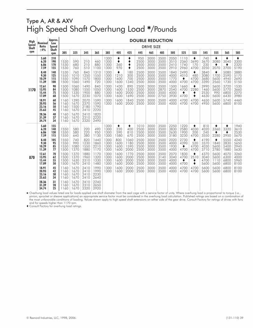
© Rexnord Industries, LLC, 1998, 2006. (131-110) 39
Type A, AR & AXV
High Speed Shaft Overhung Load �/Pounds
HighSpeedShaftrpm
NominalRatio±4%
Approx.Low
SpeedShaftrpm
DOUBLE REDUCTION
DRIVE SIZE
305 325 345 365 385 405 425 445 465 485 505 525 535 545 555 565 585
1170
5.60 210 . . . . . . . . . . . . 1300 � � 950 3000 3500 2050 1110 � 740 � � �6.20 190 1530 590 210 460 1300 � � 2500 3000 3500 3510 2360 3690 3670 3080 3040 33006.86 170 1530 680 210 880 1300 360 � 2500 3000 3500 2410 1740 170 230 � � 23207.59 155 1530 760 510 1100 1300 970 � 2500 3000 3500 2910 2960 4700 3250 2070 2700 5190
8.40 140 1530 760 840 1310 1300 � 180 2500 3000 3500 1840 2490 � 3840 � 5080 38809.30 125 1550 1010 1250 1550 1300 1210 300 2500 3000 3500 4000 4010 480 3080 1700 2590 5170
10.29 115 1550 1090 1570 1800 1300 1600 700 2500 3000 3500 1770 � 4700 3680 5600 4940 269011.39 100 1500 1060 1490 720 1300 1600 1340 2500 3000 3500 4000 4700 4700 3390 2560 1730 5150
12.61 90 1500 1060 1490 840 1300 1430 890 2500 3000 3500 1500 1660 � 3990 5600 3720 153013.95 84 1500 1080 1550 1050 1300 1600 1530 2500 3000 2870 2540 4700 2280 1460 5600 5770 366015.44 75 1500 1330 1900 880 1300 1600 2000 2500 3000 3500 4000 � � 2530 990 6800 227017.09 68 1500 1670 2230 1070 1300 1600 1690 2500 3000 2750 3930 4700 � 4630 5600 6430 3980
18.91 60 1160 1390 2070 1590 1300 1600 1840 2500 3000 3500 4000 4700 4700 4650 5600 5740 446020.93 56 1160 1670 2370 1590 1300 1600 2000 2500 3000 3500 4000 4700 4700 4950 5600 6800 810023.16 50 1160 1500 2180 179025.63 45 1160 1670 2410 2220
28.36 40 1160 1670 2410 182031.39 37 1160 1670 2310 222034.74 34 1160 1670 2320 2490
870
5.60 155 . . . . . . . . . . . . 1300 � � 1010 3000 3500 2250 1220 � 810 � � 19406.20 140 1550 580 220 490 1300 220 400 2500 3000 3500 3830 2580 4030 4020 3360 3320 36106.86 130 1550 580 220 950 1300 590 810 2500 3000 3500 2630 1900 200 240 � � 25307.59 115 1550 640 380 1130 1300 1580 670 2500 3000 3500 3180 3230 4700 3550 2280 2950 5670
8.40 105 1550 740 820 1440 1300 800 1060 2500 3000 3500 2020 2730 � 4190 � 5550 42409.30 95 1550 990 1230 1860 1300 1600 1180 2500 3000 3500 4000 4390 520 3370 1840 2830 5650
10.29 85 1550 1080 1550 2210 1300 1600 1590 2500 3000 3500 1930 � 4700 4030 5600 5400 294011.39 77 1500 1370 1880 1170 1300 1600 2000 2500 3000 3500 4000 4700 4700 3710 2780 1880 5630
12.61 70 1500 1370 1880 1170 1300 1600 1770 2500 3000 3500 2070 1830 � 4370 5600 4070 326013.95 62 1500 1370 1960 1320 1300 1600 2000 2500 3000 3140 3040 4700 2510 3040 5600 6300 400015.44 55 1500 1630 2310 1330 1300 1600 2000 2500 3000 3500 4000 � � 4700 1110 6800 596017.09 50 1500 1670 2410 1480 1300 1600 2000 2500 3000 3500 4000 4700 � 5600 5600 6800 8100
18.91 45 1160 1670 2410 1990 1300 1600 2000 2500 3000 3500 4000 4700 4700 5600 5600 6800 810020.93 42 1160 1670 2410 1990 1300 1600 2000 2500 3000 3500 4000 4700 4700 5600 5600 6800 810023.16 38 1160 1670 2410 223025.63 34 1160 1670 2410 2640
28.36 31 1160 1670 2410 224031.39 28 1160 1670 2310 265034.74 25 1160 1670 2320 2920
� Overhung load values listed are for loads applied one shaft diameter from the seal cage with a service factor of unity. Where overhung load is proportional to torque (i.e.,pinion, sprocket or sheave applications) an appropriate service factor must be considered in the overhung load calculation. Published ratings are based on a combination ofthe most unfavorable conditions of loading. Values shown apply to high speed shaft extensions on either side of the gear drive. Consult Factory for ratings of drives with fansand for speeds higher than 1170 rpm.
� Consult Factory for overhung load ratings.

40 (131-110) © Rexnord Industries, LLC, 1998, 2006.
Type A, AR & AXV
High Speed Shaft Overhung Load �/Pounds
HighSpeedShaftrpm
NominalRatio±4%
Approx.Low
SpeedShaftrpm
DOUBLE REDUCTION
DRIVE SIZE
305 325 345 365 385 405 425 445 465 485 505 525 535 545 555 565 585
720
5.60 130 . . . . . . . . . . . . 1300 430 560 1080 3000 3500 2380 1290 � 850 � � 50506.20 115 1550 580 210 710 1300 750 1020 2500 3000 3500 4000 2740 4240 4250 3540 3510 50506.86 105 1550 580 210 950 1300 1120 1400 2500 3000 3500 2780 2010 200 260 � � 50507.59 95 1550 630 370 1130 1300 1600 1270 2500 3000 3500 3360 3430 4700 3750 2400 3130 6000
8.40 85 1550 730 800 1600 1300 1340 1660 2500 3000 3500 2120 2890 � 4430 � 5880 44909.30 77 1550 990 1210 2140 1300 1600 1800 2500 3000 3500 4000 4640 550 3570 1940 3000 5980
10.29 70 1550 1080 1520 2500 1300 1600 2000 2500 3000 3500 2640 � 4700 4260 5600 5710 595011.39 62 1500 1580 2120 1460 1300 1600 2000 2500 3000 3500 4000 4700 4700 4400 2960 2630 8100
12.61 55 1500 1580 2120 1460 1300 1600 2000 2500 3000 3500 3700 1950 � 5600 5600 4420 636013.95 50 1500 1580 2230 1620 1300 1600 2000 2500 3000 3500 4000 4700 2610 5150 5600 6800 424015.44 45 1500 1670 2410 1600 1300 1600 2000 2500 3000 3500 4000 1960 � 5600 1170 6800 810017.09 42 1500 1670 2410 1730 1300 1600 2000 2500 3000 3500 4000 4700 4700 5600 5600 6800 8100
18.91 38 1160 1670 2410 2140 1300 1600 2000 2500 3000 3500 4000 4700 4700 5600 5600 6800 810020.93 34 1160 1670 2410 2140 1300 1600 2000 2500 3000 3500 4000 4700 4700 5600 5600 6800 810023.16 31 1160 1670 2410 241025.63 28 1160 1670 2410 2820
28.36 25 1160 1670 2410 236031.39 22 1160 1670 2310 278034.74 21 1160 1670 2320 3060
580
5.60 105 . . . . . . . . . . . . 1300 1090 1290 1160 3000 3500 2540 1380 � 910 � � 81006.20 95 1550 580 210 860 1300 1400 1750 2500 3000 3500 4000 2920 4550 4530 3770 3740 81006.86 85 1550 580 210 950 1300 1600 2000 2500 3000 3500 2970 2150 200 1810 � � 81007.59 77 1550 630 350 1130 1300 1600 2000 2500 3000 3500 3590 3650 4700 4010 2560 3330 6410
8.40 70 1550 730 770 1660 1300 1600 2000 2500 3000 3500 3560 3080 � 5090 5220 6270 71409.30 62 1550 980 1190 2160 1300 1600 2000 2500 3000 3500 4000 4700 610 5000 5220 4200 8100
10.29 55 1550 1080 1520 2520 1300 1600 2000 2500 3000 3500 4000 � 4700 5600 5600 6100 810011.39 50 1500 1670 2120 1460 1300 1600 2000 2500 3000 3500 4000 4700 4700 5600 3170 5560 8100
12.61 45 1500 1670 2120 1460 1300 1600 2000 2500 3000 3500 4000 4700 � 5600 5600 6800 810013.95 42 1500 1670 2230 1620 1300 1600 2000 2500 3000 3500 4000 4700 4700 5600 5600 6800 600015.44 38 1500 1670 2410 1600 1300 1600 2000 2500 3000 3500 4000 4700 430 5600 1250 6800 810017.09 34 1500 1670 2410 1730 1300 1600 2000 2500 3000 3500 4000 4700 4700 5600 5600 6800 8100
18.91 31 1160 1670 2410 2140 1300 1600 2000 2500 3000 3500 4000 4700 4700 5600 5600 6800 810020.93 28 1160 1670 2410 2140 1300 1600 2000 2500 3000 3500 4000 4700 4700 5600 5600 6800 810023.16 25 1160 1670 2410 241025.63 22 1160 1670 2410 2820
28.36 21 1160 1670 2410 236031.39 18 1160 1670 2300 278034.74 17 1160 1670 2320 3060
� Overhung load values listed are for loads applied one shaft diameter from the seal cage with a service factor of unity. Where overhung load is proportional to torque (i.e.,pinion, sprocket or sheave applications) an appropriate service factor must be considered in the overhung load calculation. Published ratings are based on a combinationof the most unfavorable conditions of loading. Values shown apply to high speed shaft extensions on either side of the gear drive. Consult Factory for ratings of drives withfans and for speeds higher than 1170 rpm.
� Consult Factory for overhung load ratings.
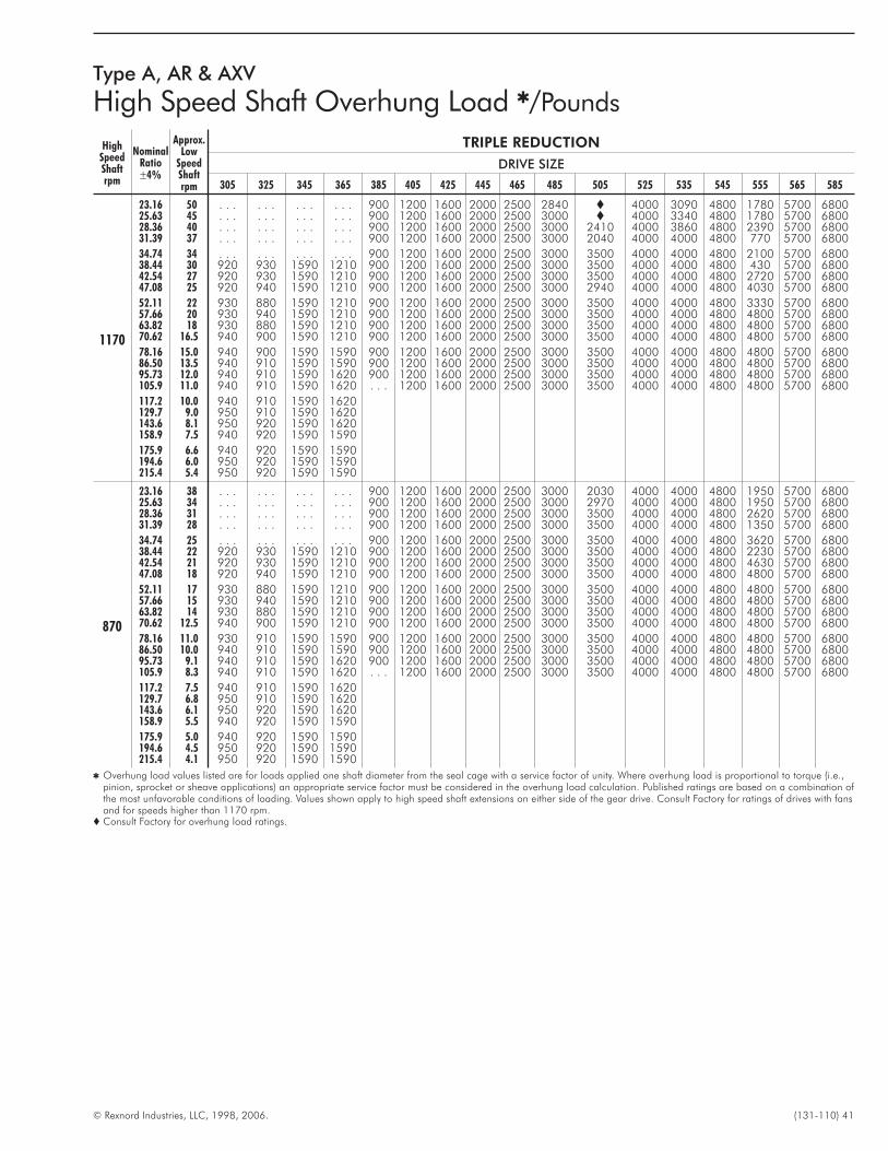
© Rexnord Industries, LLC, 1998, 2006. (131-110) 41
Type A, AR & AXV
High Speed Shaft Overhung Load �/Pounds
HighSpeedShaftrpm
NominalRatio±4%
Approx.Low
SpeedShaftrpm
TRIPLE REDUCTION
DRIVE SIZE
305 325 345 365 385 405 425 445 465 485 505 525 535 545 555 565 585
1170
23.16 50 . . . . . . . . . . . . 900 1200 1600 2000 2500 2840 � 4000 3090 4800 1780 5700 680025.63 45 . . . . . . . . . . . . 900 1200 1600 2000 2500 3000 � 4000 3340 4800 1780 5700 680028.36 40 . . . . . . . . . . . . 900 1200 1600 2000 2500 3000 2410 4000 3860 4800 2390 5700 680031.39 37 . . . . . . . . . . . . 900 1200 1600 2000 2500 3000 2040 4000 4000 4800 770 5700 6800
34.74 34 . . . . . . . . . . . . 900 1200 1600 2000 2500 3000 3500 4000 4000 4800 2100 5700 680038.44 30 920 930 1590 1210 900 1200 1600 2000 2500 3000 3500 4000 4000 4800 430 5700 680042.54 27 920 930 1590 1210 900 1200 1600 2000 2500 3000 3500 4000 4000 4800 2720 5700 680047.08 25 920 940 1590 1210 900 1200 1600 2000 2500 3000 2940 4000 4000 4800 4030 5700 6800
52.11 22 930 880 1590 1210 900 1200 1600 2000 2500 3000 3500 4000 4000 4800 3330 5700 680057.66 20 930 940 1590 1210 900 1200 1600 2000 2500 3000 3500 4000 4000 4800 4800 5700 680063.82 18 930 880 1590 1210 900 1200 1600 2000 2500 3000 3500 4000 4000 4800 4800 5700 680070.62 16.5 940 900 1590 1210 900 1200 1600 2000 2500 3000 3500 4000 4000 4800 4800 5700 6800
78.16 15.0 940 900 1590 1590 900 1200 1600 2000 2500 3000 3500 4000 4000 4800 4800 5700 680086.50 13.5 940 910 1590 1590 900 1200 1600 2000 2500 3000 3500 4000 4000 4800 4800 5700 680095.73 12.0 940 910 1590 1620 900 1200 1600 2000 2500 3000 3500 4000 4000 4800 4800 5700 6800105.9 11.0 940 910 1590 1620 . . . 1200 1600 2000 2500 3000 3500 4000 4000 4800 4800 5700 6800
117.2 10.0 940 910 1590 1620129.7 9.0 950 910 1590 1620143.6 8.1 950 920 1590 1620158.9 7.5 940 920 1590 1590
175.9 6.6 940 920 1590 1590194.6 6.0 950 920 1590 1590215.4 5.4 950 920 1590 1590
870
23.16 38 . . . . . . . . . . . . 900 1200 1600 2000 2500 3000 2030 4000 4000 4800 1950 5700 680025.63 34 . . . . . . . . . . . . 900 1200 1600 2000 2500 3000 2970 4000 4000 4800 1950 5700 680028.36 31 . . . . . . . . . . . . 900 1200 1600 2000 2500 3000 3500 4000 4000 4800 2620 5700 680031.39 28 . . . . . . . . . . . . 900 1200 1600 2000 2500 3000 3500 4000 4000 4800 1350 5700 6800
34.74 25 . . . . . . . . . . . . 900 1200 1600 2000 2500 3000 3500 4000 4000 4800 3620 5700 680038.44 22 920 930 1590 1210 900 1200 1600 2000 2500 3000 3500 4000 4000 4800 2230 5700 680042.54 21 920 930 1590 1210 900 1200 1600 2000 2500 3000 3500 4000 4000 4800 4630 5700 680047.08 18 920 940 1590 1210 900 1200 1600 2000 2500 3000 3500 4000 4000 4800 4800 5700 6800
52.11 17 930 880 1590 1210 900 1200 1600 2000 2500 3000 3500 4000 4000 4800 4800 5700 680057.66 15 930 940 1590 1210 900 1200 1600 2000 2500 3000 3500 4000 4000 4800 4800 5700 680063.82 14 930 880 1590 1210 900 1200 1600 2000 2500 3000 3500 4000 4000 4800 4800 5700 680070.62 12.5 940 900 1590 1210 900 1200 1600 2000 2500 3000 3500 4000 4000 4800 4800 5700 6800
78.16 11.0 930 910 1590 1590 900 1200 1600 2000 2500 3000 3500 4000 4000 4800 4800 5700 680086.50 10.0 940 910 1590 1590 900 1200 1600 2000 2500 3000 3500 4000 4000 4800 4800 5700 680095.73 9.1 940 910 1590 1620 900 1200 1600 2000 2500 3000 3500 4000 4000 4800 4800 5700 6800105.9 8.3 940 910 1590 1620 . . . 1200 1600 2000 2500 3000 3500 4000 4000 4800 4800 5700 6800
117.2 7.5 940 910 1590 1620129.7 6.8 950 910 1590 1620143.6 6.1 950 920 1590 1620158.9 5.5 940 920 1590 1590
175.9 5.0 940 920 1590 1590194.6 4.5 950 920 1590 1590215.4 4.1 950 920 1590 1590
� Overhung load values listed are for loads applied one shaft diameter from the seal cage with a service factor of unity. Where overhung load is proportional to torque (i.e.,pinion, sprocket or sheave applications) an appropriate service factor must be considered in the overhung load calculation. Published ratings are based on a combination ofthe most unfavorable conditions of loading. Values shown apply to high speed shaft extensions on either side of the gear drive. Consult Factory for ratings of drives with fansand for speeds higher than 1170 rpm.
� Consult Factory for overhung load ratings.
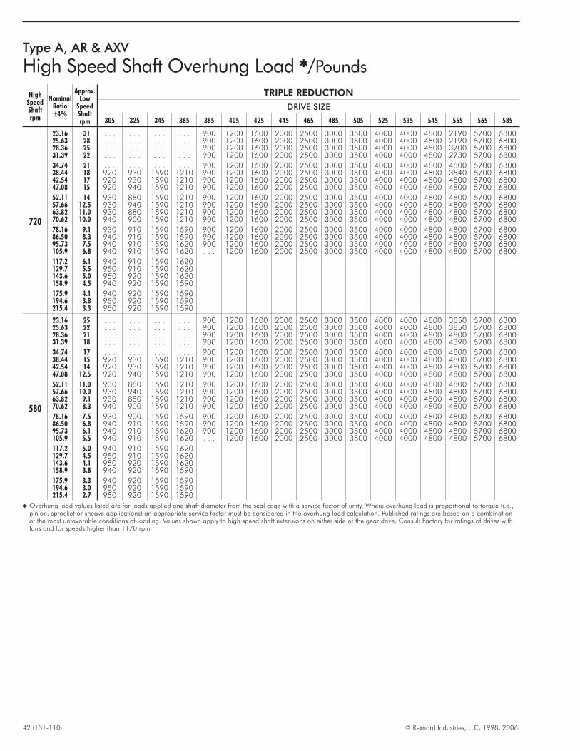
42 (131-110) © Rexnord Industries, LLC, 1998, 2006.
Type A, AR & AXV
High Speed Shaft Overhung Load �/Pounds
HighSpeedShaftrpm
NominalRatio±4%
Approx.Low
SpeedShaftrpm
TRIPLE REDUCTION
DRIVE SIZE
305 325 345 365 385 405 425 445 465 485 505 525 535 545 555 565 585
720
23.16 31 . . . . . . . . . . . . 900 1200 1600 2000 2500 3000 3500 4000 4000 4800 2190 5700 680025.63 28 . . . . . . . . . . . . 900 1200 1600 2000 2500 3000 3500 4000 4000 4800 2190 5700 680028.36 25 . . . . . . . . . . . . 900 1200 1600 2000 2500 3000 3500 4000 4000 4800 3700 5700 680031.39 22 . . . . . . . . . . . . 900 1200 1600 2000 2500 3000 3500 4000 4000 4800 2730 5700 6800
34.74 21 . . . . . . . . . . . . 900 1200 1600 2000 2500 3000 3500 4000 4000 4800 4800 5700 680038.44 18 920 930 1590 1210 900 1200 1600 2000 2500 3000 3500 4000 4000 4800 3540 5700 680042.54 17 920 930 1590 1210 900 1200 1600 2000 2500 3000 3500 4000 4000 4800 4800 5700 680047.08 15 920 940 1590 1210 900 1200 1600 2000 2500 3000 3500 4000 4000 4800 4800 5700 6800
52.11 14 930 880 1590 1210 900 1200 1600 2000 2500 3000 3500 4000 4000 4800 4800 5700 680057.66 12.5 930 940 1590 1210 900 1200 1600 2000 2500 3000 3500 4000 4000 4800 4800 5700 680063.82 11.0 930 880 1590 1210 900 1200 1600 2000 2500 3000 3500 4000 4000 4800 4800 5700 680070.62 10.0 940 900 1590 1210 900 1200 1600 2000 2500 3000 3500 4000 4000 4800 4800 5700 6800
78.16 9.1 930 910 1590 1590 900 1200 1600 2000 2500 3000 3500 4000 4000 4800 4800 5700 680086.50 8.3 940 910 1590 1590 900 1200 1600 2000 2500 3000 3500 4000 4000 4800 4800 5700 680095.73 7.5 940 910 1590 1620 900 1200 1600 2000 2500 3000 3500 4000 4000 4800 4800 5700 6800105.9 6.8 940 910 1590 1620 . . . 1200 1600 2000 2500 3000 3500 4000 4000 4800 4800 5700 6800
117.2 6.1 940 910 1590 1620129.7 5.5 950 910 1590 1620143.6 5.0 950 920 1590 1620158.9 4.5 940 920 1590 1590
175.9 4.1 940 920 1590 1590194.6 3.8 950 920 1590 1590215.4 3.3 950 920 1590 1590
580
23.16 25 . . . . . . . . . . . . 900 1200 1600 2000 2500 3000 3500 4000 4000 4800 3850 5700 680025.63 22 . . . . . . . . . . . . 900 1200 1600 2000 2500 3000 3500 4000 4000 4800 3850 5700 680028.36 21 . . . . . . . . . . . . 900 1200 1600 2000 2500 3000 3500 4000 4000 4800 4800 5700 680031.39 18 . . . . . . . . . . . . 900 1200 1600 2000 2500 3000 3500 4000 4000 4800 4390 5700 6800
34.74 17 . . . . . . . . . . . . 900 1200 1600 2000 2500 3000 3500 4000 4000 4800 4800 5700 680038.44 15 920 930 1590 1210 900 1200 1600 2000 2500 3000 3500 4000 4000 4800 4800 5700 680042.54 14 920 930 1590 1210 900 1200 1600 2000 2500 3000 3500 4000 4000 4800 4800 5700 680047.08 12.5 920 940 1590 1210 900 1200 1600 2000 2500 3000 3500 4000 4000 4800 4800 5700 6800
52.11 11.0 930 880 1590 1210 900 1200 1600 2000 2500 3000 3500 4000 4000 4800 4800 5700 680057.66 10.0 930 940 1590 1210 900 1200 1600 2000 2500 3000 3500 4000 4000 4800 4800 5700 680063.82 9.1 930 880 1590 1210 900 1200 1600 2000 2500 3000 3500 4000 4000 4800 4800 5700 680070.62 8.3 940 900 1590 1210 900 1200 1600 2000 2500 3000 3500 4000 4000 4800 4800 5700 6800
78.16 7.5 930 900 1590 1590 900 1200 1600 2000 2500 3000 3500 4000 4000 4800 4800 5700 680086.50 6.8 940 910 1590 1590 900 1200 1600 2000 2500 3000 3500 4000 4000 4800 4800 5700 680095.73 6.1 940 910 1590 1620 900 1200 1600 2000 2500 3000 3500 4000 4000 4800 4800 5700 6800105.9 5.5 940 910 1590 1620 . . . 1200 1600 2000 2500 3000 3500 4000 4000 4800 4800 5700 6800
117.2 5.0 940 910 1590 1620129.7 4.5 950 910 1590 1620143.6 4.1 950 920 1590 1620158.9 3.8 940 920 1590 1590
175.9 3.3 940 920 1590 1590194.6 3.0 950 920 1590 1590215.4 2.7 950 920 1590 1590
� Overhung load values listed are for loads applied one shaft diameter from the seal cage with a service factor of unity. Where overhung load is proportional to torque (i.e.,pinion, sprocket or sheave applications) an appropriate service factor must be considered in the overhung load calculation. Published ratings are based on a combinationof the most unfavorable conditions of loading. Values shown apply to high speed shaft extensions on either side of the gear drive. Consult Factory for ratings of drives withfans and for speeds higher than 1170 rpm.

© Rexnord Industries, LLC, 1998, 2006. (131-110) 43
Type A, AR & AXV
High Speed Shaft Overhung Load �/Pounds
HighSpeedShaftrpm
NominalRatio±5%
Approx.Low Speed Shaft
rpm
QUADRUPLE REDUCTION
DRIVE SIZE
385 405 425 445 465 485 505 525 535 555
1170105.9 11.0 600117.2 10.0 600 800 1000 1200 1500 1700 2000 2300 2300 1850
129.7 or Higher 9.0 or Lower 600 800 1000 1200 1500 1700 2000 2300 2300 3000
870105.9 8.3 600
117.2 or Higher 7.5 or Lower 600 800 1000 1200 1500 1700 2000 2300 2300 3000
Type A
Low Speed Shaft Overhung Load Ratings �/PoundsMultiply values below by 1000
HighSpeedShaftrpm
NominalRatio±3%
Approx.Low SpeedShaft rpm
SINGLE REDUCTION
DRIVE SIZE
305 325 345 365 385 405 425 445 465 485 505 525
1750
1.84 950 3.21 5.64 5.72 7.98 12.5 6.08 � 10.00 2.45 � � 7.182.03 860 3.15 5.82 5.94 8.34 12.5 6.60 2.74 11.6 5.91 � � 9.312.25 780 3.17 6.04 6.15 8.74 12.5 7.24 3.88 12.8 8.51 � � 12.02.49 700 3.17 6.25 6.38 8.96 12.5 7.96 5.24 14.6 10.6 � � 13.5
2.76 640 3.15 6.56 6.63 9.32 12.5 8.14 6.50 17.0 11.9 3.88 � 15.93.05 575 3.17 6.79 6.98 9.68 12.5 8.93 6.79 17.5 12.9 6.81 2.88 16.73.38 520 3.21 7.03 7.22 9.95 12.5 8.45 7.44 18.8 13.8 11.6 7.11 18.83.74 470 3.17 7.24 7.44 10.4 12.5 9.40 7.97 19.6 15.1 14.4 12.7 21.3
4.13 420 3.21 7.53 7.72 10.8 12.5 11.6 9.27 20.3 16.8 20.1 19.8 25.04.57 380 3.33 7.89 8.07 11.3 12.5 12.2 10.3 21.2 18.0 23.6 24.0 26.65.06 350 3.52 7.96 8.70 11.7 12.5 13.9 12.1 22.7 18.8 25.0 29.5 37.05.60 310 3.56 7.96 9.11 12.1
1170
1.84 640 3.02 6.36 6.75 9.00 12.5 6.86 � 11.3 2.75 � � 8.102.03 575 2.95 6.57 6.88 9.41 12.5 7.45 3.10 13.1 6.67 � � 10.52.25 520 2.98 6.82 6.93 9.86 12.5 8.17 4.38 14.5 9.60 � � 13.62.49 470 2.97 7.05 7.20 10.1 12.5 8.99 5.91 16.5 12.0 � � 15.2
2.76 420 2.95 7.40 7.49 10.5 12.5 9.18 7.33 19.2 13.5 4.38 � 17.93.05 380 2.98 7.66 8.13 10.9 12.5 10.1 7.67 19.8 14.5 7.68 3.25 18.83.38 350 3.01 7.75 8.14 11.2 12.5 10.5 8.40 21.2 15.6 13.1 8.04 21.23.74 310 2.98 7.75 8.39 11.8 12.5 11.5 9.28 22.1 17.0 18.1 14.3 24.0
4.13 280 3.07 7.73 8.71 12.1 12.5 14.1 12.0 22.9 19.0 22.7 22.4 30.94.57 255 3.29 7.75 9.11 12.1 12.5 14.7 13.1 23.9 20.3 28.0 27.5 33.25.06 230 3.49 7.90 10.1 12.0 12.5 15.0 14.9 25.0 21.2 31.6 38.7 48.55.60 210 3.54 7.92 10.5 12.1
580
1.84 320 3.02 7.74 9.02 11.7 10.8 8.47 6.84 18.2 3.41 3.72 8.06 10.02.03 290 2.92 7.65 9.20 11.7 11.3 9.20 3.82 16.2 8.22 � � 13.02.25 260 2.77 7.52 9.25 11.5 9.86 10.1 7.93 17.8 12.2 � � 17.02.49 235 2.68 7.41 9.42 11.5 10.3 11.1 8.40 20.4 14.8 � � 19.9
2.76 210 2.77 7.34 9.69 11.5 10.4 12.4 9.96 24.0 16.6 5.41 � 22.13.05 190 2.81 7.51 10.6 11.5 11.7 13.1 10.9 24.8 17.9 9.48 3.98 23.33.38 175 2.88 7.35 10.4 11.5 11.4 15.0 12.6 25.0 19.2 34.2 9.94 26.23.74 155 2.92 7.40 10.8 11.5 12.4 15.0 14.1 25.0 21.0 37.8 34.1 31.0
4.13 140 3.02 7.55 11.0 11.5 12.5 15.0 17.2 25.0 23.4 37.7 38.5 52.24.57 130 3.25 7.69 11.5 11.7 12.5 15.0 18.0 25.0 30.7 40.0 44.2 54.65.06 115 3.46 7.86 11.6 11.9 12.5 15.0 18.0 25.0 31.9 40.0 50.0 60.05.60 105 3.50 7.87 11.7 12.1
� Published ratings are for standard assemblies with shaft extensions as shown on Page 17 and are based on the most unfavorable conditions of loading. Interpolate forspeeds between those shown. For speeds below 580 rpm use ratings for 580 rpm.
� Consult Factory for overhung load ratings.
� Overhung load values listed are for loads applied one shaft diameter from the seal cage with a service factor of unity. Where overhung load is proportional to torque (i.e.,pinion, sprocket or sheave applications) an appropriate service factor must be considered in the overhung load calculation. Published ratings are based on a combination ofthe most unfavorable conditions of loading. Values shown apply to high speed shaft extensions on either side of the gear drive. Consult Factory for ratings of drives withfans.
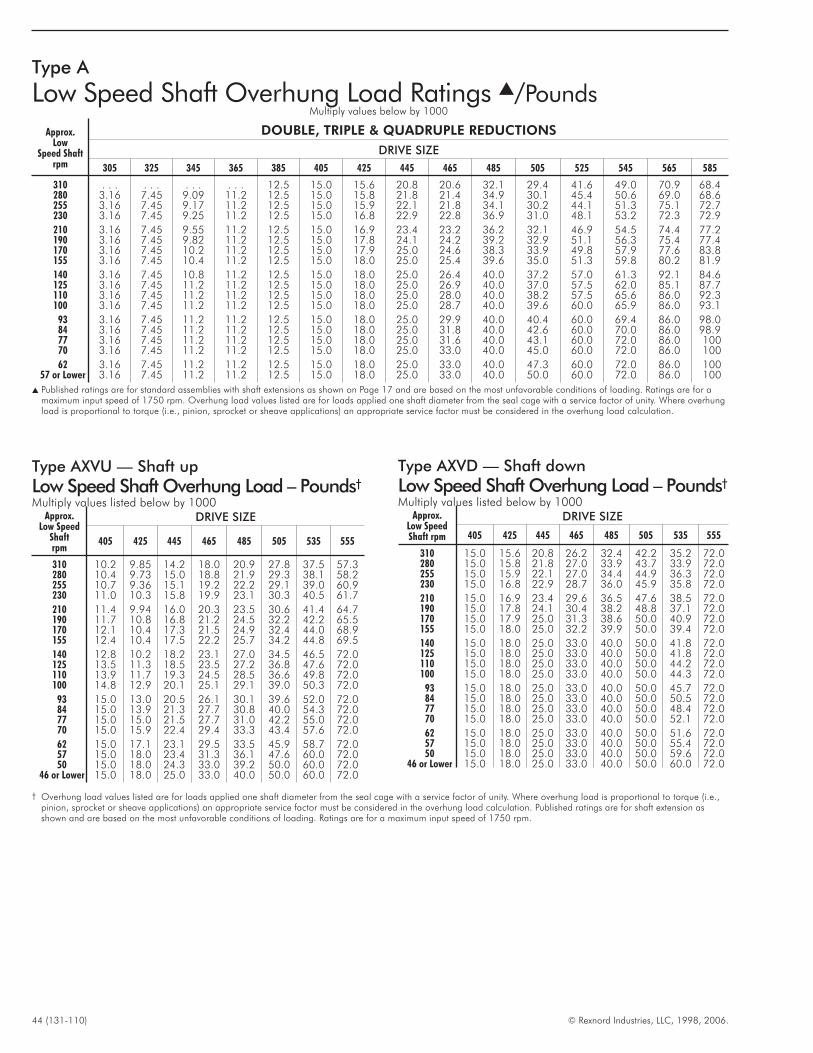
44 (131-110) © Rexnord Industries, LLC, 1998, 2006.
Type A
Low Speed Shaft Overhung Load Ratings �/PoundsMultiply values below by 1000
Approx.Low
Speed Shaftrpm
DOUBLE, TRIPLE & QUADRUPLE REDUCTIONS
DRIVE SIZE
305 325 345 365 385 405 425 445 465 485 505 525 545 565 585
310 . . . . . . . . . . . . 12.5 15.0 15.6 20.8 20.6 32.1 29.4 41.6 49.0 70.9 68.4280 3.16 7.45 9.09 11.2 12.5 15.0 15.8 21.8 21.4 34.9 30.1 45.4 50.6 69.0 68.6255 3.16 7.45 9.17 11.2 12.5 15.0 15.9 22.1 21.8 34.1 30.2 44.1 51.3 75.1 72.7230 3.16 7.45 9.25 11.2 12.5 15.0 16.8 22.9 22.8 36.9 31.0 48.1 53.2 72.3 72.9
210 3.16 7.45 9.55 11.2 12.5 15.0 16.9 23.4 23.2 36.2 32.1 46.9 54.5 74.4 77.2190 3.16 7.45 9.82 11.2 12.5 15.0 17.8 24.1 24.2 39.2 32.9 51.1 56.3 75.4 77.4170 3.16 7.45 10.2 11.2 12.5 15.0 17.9 25.0 24.6 38.3 33.9 49.8 57.9 77.6 83.8155 3.16 7.45 10.4 11.2 12.5 15.0 18.0 25.0 25.4 39.6 35.0 51.3 59.8 80.2 81.9
140 3.16 7.45 10.8 11.2 12.5 15.0 18.0 25.0 26.4 40.0 37.2 57.0 61.3 92.1 84.6125 3.16 7.45 11.2 11.2 12.5 15.0 18.0 25.0 26.9 40.0 37.0 57.5 62.0 85.1 87.7110 3.16 7.45 11.2 11.2 12.5 15.0 18.0 25.0 28.0 40.0 38.2 57.5 65.6 86.0 92.3100 3.16 7.45 11.2 11.2 12.5 15.0 18.0 25.0 28.7 40.0 39.6 60.0 65.9 86.0 93.1
93 3.16 7.45 11.2 11.2 12.5 15.0 18.0 25.0 29.9 40.0 40.4 60.0 69.4 86.0 98.084 3.16 7.45 11.2 11.2 12.5 15.0 18.0 25.0 31.8 40.0 42.6 60.0 70.0 86.0 98.977 3.16 7.45 11.2 11.2 12.5 15.0 18.0 25.0 31.6 40.0 43.1 60.0 72.0 86.0 10070 3.16 7.45 11.2 11.2 12.5 15.0 18.0 25.0 33.0 40.0 45.0 60.0 72.0 86.0 100
62 3.16 7.45 11.2 11.2 12.5 15.0 18.0 25.0 33.0 40.0 47.3 60.0 72.0 86.0 10057 or Lower 3.16 7.45 11.2 11.2 12.5 15.0 18.0 25.0 33.0 40.0 50.0 60.0 72.0 86.0 100
� Published ratings are for standard assemblies with shaft extensions as shown on Page 17 and are based on the most unfavorable conditions of loading. Ratings are for amaximum input speed of 1750 rpm. Overhung load values listed are for loads applied one shaft diameter from the seal cage with a service factor of unity. Where overhungload is proportional to torque (i.e., pinion, sprocket or sheave applications) an appropriate service factor must be considered in the overhung load calculation.
Type AXVU — Shaft up
Low Speed Shaft Overhung Load – Pounds†
Multiply values listed below by 1000Approx.
Low SpeedShaftrpm
DRIVE SIZE
405 425 445 465 485 505 535 555
310 10.2 9.85 14.2 18.0 20.9 27.8 37.5 57.3280 10.4 9.73 15.0 18.8 21.9 29.3 38.1 58.2255 10.7 9.36 15.1 19.2 22.2 29.1 39.0 60.9230 11.0 10.3 15.8 19.9 23.1 30.3 40.5 61.7
210 11.4 9.94 16.0 20.3 23.5 30.6 41.4 64.7190 11.7 10.8 16.8 21.2 24.5 32.2 42.2 65.5170 12.1 10.4 17.3 21.5 24.9 32.4 44.0 68.9155 12.4 10.4 17.5 22.2 25.7 34.2 44.8 69.5
140 12.8 10.2 18.2 23.1 27.0 34.5 46.5 72.0125 13.5 11.3 18.5 23.5 27.2 36.8 47.6 72.0110 13.9 11.7 19.3 24.5 28.5 36.6 49.8 72.0100 14.8 12.9 20.1 25.1 29.1 39.0 50.3 72.0
93 15.0 13.0 20.5 26.1 30.1 39.6 52.0 72.084 15.0 13.9 21.3 27.7 30.8 40.0 54.3 72.077 15.0 15.0 21.5 27.7 31.0 42.2 55.0 72.070 15.0 15.9 22.4 29.4 33.3 43.4 57.6 72.0
62 15.0 17.1 23.1 29.5 33.5 45.9 58.7 72.057 15.0 18.0 23.4 31.3 36.1 47.6 60.0 72.050 15.0 18.0 24.3 33.0 39.2 50.0 60.0 72.0
46 or Lower 15.0 18.0 25.0 33.0 40.0 50.0 60.0 72.0
Type AXVD — Shaft down
Low Speed Shaft Overhung Load – Pounds†
Multiply values listed below by 1000Approx.
Low SpeedShaft rpm
DRIVE SIZE
405 425 445 465 485 505 535 555
310 15.0 15.6 20.8 26.2 32.4 42.2 35.2 72.0280 15.0 15.8 21.8 27.0 33.9 43.7 33.9 72.0255 15.0 15.9 22.1 27.0 34.4 44.9 36.3 72.0230 15.0 16.8 22.9 28.7 36.0 45.9 35.8 72.0
210 15.0 16.9 23.4 29.6 36.5 47.6 38.5 72.0190 15.0 17.8 24.1 30.4 38.2 48.8 37.1 72.0170 15.0 17.9 25.0 31.3 38.6 50.0 40.9 72.0155 15.0 18.0 25.0 32.2 39.9 50.0 39.4 72.0
140 15.0 18.0 25.0 33.0 40.0 50.0 41.8 72.0125 15.0 18.0 25.0 33.0 40.0 50.0 41.8 72.0110 15.0 18.0 25.0 33.0 40.0 50.0 44.2 72.0100 15.0 18.0 25.0 33.0 40.0 50.0 44.3 72.0
93 15.0 18.0 25.0 33.0 40.0 50.0 45.7 72.084 15.0 18.0 25.0 33.0 40.0 50.0 50.5 72.077 15.0 18.0 25.0 33.0 40.0 50.0 48.4 72.070 15.0 18.0 25.0 33.0 40.0 50.0 52.1 72.0
62 15.0 18.0 25.0 33.0 40.0 50.0 51.6 72.057 15.0 18.0 25.0 33.0 40.0 50.0 55.4 72.050 15.0 18.0 25.0 33.0 40.0 50.0 59.6 72.0
46 or Lower 15.0 18.0 25.0 33.0 40.0 50.0 60.0 72.0
† Overhung load values listed are for loads applied one shaft diameter from the seal cage with a service factor of unity. Where overhung load is proportional to torque (i.e.,pinion, sprocket or sheave applications) an appropriate service factor must be considered in the overhung load calculation. Published ratings are for shaft extension asshown and are based on the most unfavorable conditions of loading. Ratings are for a maximum input speed of 1750 rpm.
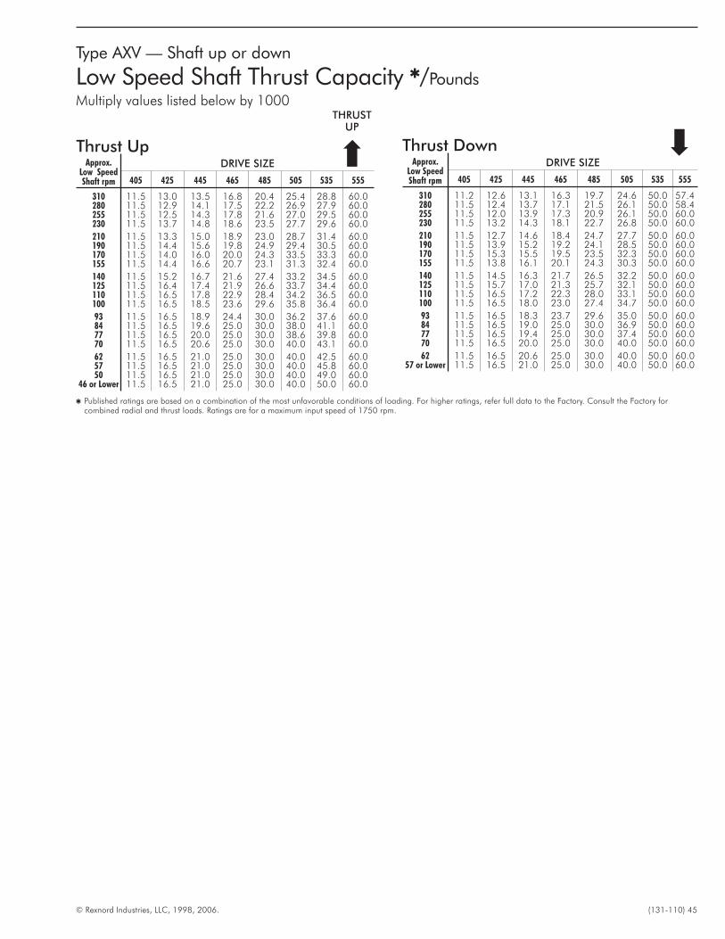
© Rexnord Industries, LLC, 1998, 2006. (131-110) 45
Thrust UpApprox.
Low SpeedShaft rpm
DRIVE SIZE
405 425 445 465 485 505 535 555
310 11.5 13.0 13.5 16.8 20.4 25.4 28.8 60.0280 11.5 12.9 14.1 17.5 22.2 26.9 27.9 60.0255 11.5 12.5 14.3 17.8 21.6 27.0 29.5 60.0230 11.5 13.7 14.8 18.6 23.5 27.7 29.6 60.0
210 11.5 13.3 15.0 18.9 23.0 28.7 31.4 60.0190 11.5 14.4 15.6 19.8 24.9 29.4 30.5 60.0170 11.5 14.0 16.0 20.0 24.3 33.5 33.3 60.0155 11.5 14.4 16.6 20.7 23.1 31.3 32.4 60.0
140 11.5 15.2 16.7 21.6 27.4 33.2 34.5 60.0125 11.5 16.4 17.4 21.9 26.6 33.7 34.4 60.0110 11.5 16.5 17.8 22.9 28.4 34.2 36.5 60.0100 11.5 16.5 18.5 23.6 29.6 35.8 36.4 60.0
93 11.5 16.5 18.9 24.4 30.0 36.2 37.6 60.084 11.5 16.5 19.6 25.0 30.0 38.0 41.1 60.077 11.5 16.5 20.0 25.0 30.0 38.6 39.8 60.070 11.5 16.5 20.6 25.0 30.0 40.0 43.1 60.0
62 11.5 16.5 21.0 25.0 30.0 40.0 42.5 60.057 11.5 16.5 21.0 25.0 30.0 40.0 45.8 60.050 11.5 16.5 21.0 25.0 30.0 40.0 49.0 60.0
46 or Lower 11.5 16.5 21.0 25.0 30.0 40.0 50.0 60.0
Thrust DownApprox.
Low SpeedShaft rpm
DRIVE SIZE
405 425 445 465 485 505 535 555
310 11.2 12.6 13.1 16.3 19.7 24.6 50.0 57.4280 11.5 12.4 13.7 17.1 21.5 26.1 50.0 58.4255 11.5 12.0 13.9 17.3 20.9 26.1 50.0 60.0230 11.5 13.2 14.3 18.1 22.7 26.8 50.0 60.0
210 11.5 12.7 14.6 18.4 24.7 27.7 50.0 60.0190 11.5 13.9 15.2 19.2 24.1 28.5 50.0 60.0170 11.5 15.3 15.5 19.5 23.5 32.3 50.0 60.0155 11.5 13.8 16.1 20.1 24.3 30.3 50.0 60.0
140 11.5 14.5 16.3 21.7 26.5 32.2 50.0 60.0125 11.5 15.7 17.0 21.3 25.7 32.1 50.0 60.0110 11.5 16.5 17.2 22.3 28.0 33.1 50.0 60.0100 11.5 16.5 18.0 23.0 27.4 34.7 50.0 60.0
93 11.5 16.5 18.3 23.7 29.6 35.0 50.0 60.084 11.5 16.5 19.0 25.0 30.0 36.9 50.0 60.077 11.5 16.5 19.4 25.0 30.0 37.4 50.0 60.070 11.5 16.5 20.0 25.0 30.0 40.0 50.0 60.0
62 11.5 16.5 20.6 25.0 30.0 40.0 50.0 60.057 or Lower 11.5 16.5 21.0 25.0 30.0 40.0 50.0 60.0
Type AXV — Shaft up or down
Low Speed Shaft Thrust Capacity �/Pounds
Multiply values listed below by 1000
�THRUSTUP
� Published ratings are based on a combination of the most unfavorable conditions of loading. For higher ratings, refer full data to the Factory. Consult the Factory forcombined radial and thrust loads. Ratings are for a maximum input speed of 1750 rpm.
�
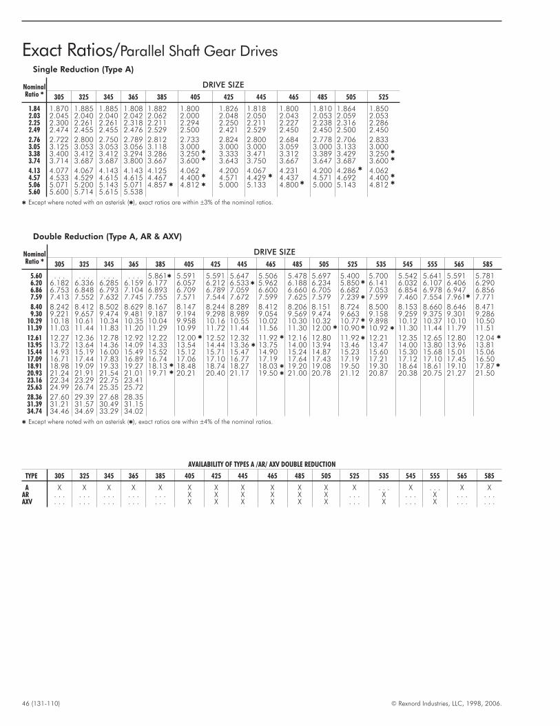
46 (131-110) © Rexnord Industries, LLC, 1998, 2006.
Exact Ratios/Parallel Shaft Gear DrivesSingle Reduction (Type A)
NominalRatio �
DRIVE SIZE
305 325 345 365 385 405 425 445 465 485 505 525
1.84 1.870 1.885 1.885 1.808 1.882 1.800 1.826 1.818 1.800 1.810 1.864 1.8502.03 2.045 2.040 2.040 2.042 2.062 2.000 2.048 2.050 2.043 2.053 2.059 2.0532.25 2.300 2.261 2.261 2.318 2.211 2.294 2.250 2.211 2.227 2.238 2.316 2.2862.49 2.474 2.455 2.455 2.476 2.529 2.500 2.421 2.529 2.450 2.450 2.500 2.450
2.76 2.722 2.800 2.750 2.789 2.812 2.733 2.824 2.800 2.684 2.778 2.706 2.8333.05 3.125 3.053 3.053 3.056 3.118 3.000 3.000 3.000 3.059 3.000 3.133 3.0003.38 3.400 3.412 3.412 3.294 3.286 3.250 � 3.333 3.471 3.312 3.389 3.429 3.250 �
3.74 3.714 3.687 3.687 3.800 3.667 3.600 � 3.643 3.750 3.667 3.647 3.687 3.600 �
4.13 4.077 4.067 4.143 4.143 4.125 4.062 4.200 4.067 4.231 4.200 4.286 � 4.0624.57 4.533 4.529 4.615 4.615 4.467 4.400 � 4.571 4.429 � 4.437 4.571 4.692 4.400 �
5.06 5.071 5.200 5.143 5.071 4.857 � 4.812 � 5.000 5.133 4.800 � 5.000 5.143 4.812 �
5.60 5.600 5.714 5.615 5.538
� Except where noted with an asterisk (�), exact ratios are within ±3% of the nominal ratios.
Double Reduction (Type A, AR & AXV)
NominalRatio �
DRIVE SIZE
305 325 345 365 385 405 425 445 465 485 505 525 535 545 555 565 585
5.60 . . . . . . . . . . . . 5.861� 5.591 5.591 5.647 5.506 5.478 5.697 5.400 5.700 5.542 5.641 5.591 5.7816.20 6.182 6.336 6.285 6.159 6.177 6.057 6.212 6.533 � 5.962 6.188 6.234 5.850 � 6.141 6.032 6.107 6.406 6.2906.86 6.753 6.848 6.793 7.104 6.893 6.709 6.789 7.059 6.600 6.660 6.705 6.682 7.053 6.854 6.978 6.947 6.8567.59 7.413 7.552 7.632 7.745 7.755 7.571 7.544 7.672 7.599 7.625 7.579 7.239 � 7.599 7.460 7.554 7.961� 7.771
8.40 8.242 8.412 8.502 8.629 8.167 8.147 8.244 8.289 8.412 8.206 8.151 8.724 8.500 8.153 8.660 8.646 8.4719.30 9.221 9.657 9.474 9.481 9.187 9.194 9.298 8.989 9.054 9.569 9.474 9.663 9.158 9.259 9.375 9.301 9.286
10.29 10.18 10.61 10.34 10.35 10.04 9.958 10.16 10.55 10.02 10.30 10.32 10.77 � 9.898 10.12 10.37 10.10 10.5011.39 11.03 11.44 11.83 11.20 11.29 10.99 11.72 11.44 11.56 11.30 12.00 � 10.90 � 10.92 � 11.30 11.44 11.79 11.51
12.61 12.27 12.36 12.78 12.92 12.22 12.00 � 12.52 12.32 11.92 � 12.16 12.80 11.92 � 12.21 12.35 12.65 12.80 12.04 �
13.95 13.72 13.64 14.36 14.09 14.33 13.54 14.44 13.36 � 13.75 14.00 13.94 13.46 13.47 14.00 13.80 13.96 13.8115.44 14.93 15.19 16.00 15.49 15.52 15.12 15.71 15.47 14.90 15.24 14.87 15.23 15.60 15.30 15.68 15.01 15.0617.09 16.71 17.44 17.83 16.89 16.74 17.06 17.10 16.77 17.19 17.64 17.43 17.19 17.21 17.12 17.10 17.45 16.5018.91 18.98 19.09 19.33 19.27 18.13 � 18.48 18.74 18.27 18.03 � 19.20 19.08 19.50 19.30 18.64 18.61 19.10 17.87 �
20.93 21.24 21.91 21.54 21.01 19.71 � 20.21 20.40 21.17 19.50 � 21.00 20.78 21.12 20.87 20.38 20.75 21.27 21.5023.16 22.34 23.29 22.75 23.4125.63 24.99 26.74 25.35 25.72
28.36 27.60 29.39 27.68 28.3531.39 31.21 31.57 30.49 31.1534.74 34.46 34.69 33.29 34.02
� Except where noted with an asterisk (�), exact ratios are within ±4% of the nominal ratios.
AVAILABILITY OF TYPES A /AR/ AXV DOUBLE REDUCTION
TYPE 305 325 345 365 385 405 425 445 465 485 505 525 535 545 555 565 585
A X X X X X X X X X X X X . . . X . . . X XAR . . . . . . . . . . . . . . . X X X X X X . . . X . . . X . . . . . .AXV . . . . . . . . . . . . . . . X X X X X X . . . X . . . X . . . . . .
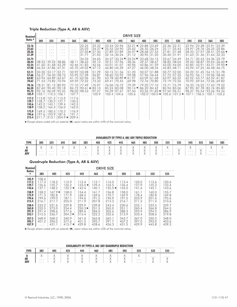
© Rexnord Industries, LLC, 1998, 2006. (131-110) 47
Quadruple Reduction (Type A, AR & AXV)
NominalRatios
�
DRIVE SIZE
385 405 425 445 465 485 505 525 535 555
105.9 108.4117.2 117.3 118.2 115.9 113.4 112.1 116.0 113.4 120.0 113.6 120.6129.7 126.6 125.7 126.2 123.0 � 129.4 124.5 126.4 127.9 125.3 133.4143.6 137.1 148.2 135.2 � 142.4 140.1 135.5 � 145.0 141.6 145.1 143.6
158.9 158.2 167.9 � 158.0 154.4 161.7 156.8 158.0 161.1 160.0 155.7175.9 171.3 182.8 171.9 168.2 169.6 170.7 169.9 178.4 182.8 169.8194.6 199.6 199.0 187.1 194.6 191.5 196.9 197.5 203.9 201.6 195.6215.4 216.1 217.7 205.0 211.9 207.8 214.3 216.1 211.2 211.4 210.6
238.4 233.2 231.6 229.8 229.9 239.8 243.4 230.6 235.1 233.5 229.7263.8 252.5 273.0 254.4 250.3 � 251.5 265.0 251.1 260.4 266.8 264.5291.9 291.4 298.6 277.6 289.6 284.0 305.6 288.3 293.9 294.2 286.9323.1 315.5 336.7 304.2 � 315.4 322.2 332.6 313.9 333.4 308.6 319.8
357.5 368.9 368.2 340.9 341.6 365.8 362.1 343.7 367.0 350.2 348.0395.7 401.2 396.0 377.6 401.5 395.7 391.7 407.2 397.0 393.0 403.6437.9 . . . 431.1 413.7 � 429.8 428.6 426.3 431.5 429.9 445.8 439.3
� Except where noted with an asterisk (�), exact ratios are within ±5% of the nominal ratios.
Triple Reduction (Type A, AR & AXV)
NominalRatio �
DRIVE SIZE
305 325 345 365 385 405 425 445 465 485 505 525 535 545 555 565 585
23.16 . . . . . . . . . . . . 22.25 22.32 23.54 22.96 22.21 � 22.88 23.69 22.36 22.31 22.94 22.38 22.91 23.3925.63 . . . . . . . . . . . . 25.03 24.37 � 25.52 24.90 25.62 26.35 26.24 25.11 25.43 24.97 24.76 26.25 25.8628.36 . . . . . . . . . . . . 27.05 � 27.50 27.89 27.89 26.97 � 28.68 27.53 27.81 27.48 28.33 27.97 28.51 29.66 �
31.39 . . . . . . . . . . . . 31.77 31.03 32.16 30.24 31.12 30.95 31.20 30.40 31.91 31.63 31.36 31.64 32.33
34.74 . . . . . . . . . . . . 34.33 34.65 34.27 33.34 � 33.24 � 33.68 34.12 33.67 34.49 34.71 35.43 34.36 33.7938.44 38.23 39.22 38.86 38.11 38.63 39.10 39.51 37.96 38.36 39.37 38.67 38.82 38.04 39.20 38.87 39.04 36.60 �
42.54 41.60 41.68 43.29 42.46 41.83 42.56 43.01 41.07 40.96 42.86 41.59 43.00 44.05 42.85 43.91 43.21 39.90 �
47.08 46.54 47.86 47.31 45.70 49.02 � 47.12 46.80 45.39 47.27 46.00 48.34 45.83 48.11 45.94 47.25 46.48 46.75
52.11 50.30 53.17 52.71 50.92 53.08 51.29 50.15 51.56 51.20 50.07 51.88 50.77 52.00 50.20 51.45 54.15 51.7857.66 56.27 56.50 58.73 55.95 57.28 56.87 58.60 55.92 59.08 57.96 56.64 57.75 57.35 56.93 56.11 59.06 58.4463.82 63.94 64.89 63.67 61.10 62.06 61.90 63.78 60.89 � 61.97 63.09 61.68 63.97 65.52 62.22 63.77 63.52 61.8770.62 71.53 73.82 70.94 69.59 72.52 73.33 69.41 70.45 69.98 72.76 70.80 72.19 72.26 70.92 69.54 72.06 69.82
78.16 78.31 81.12 80.93 77.10 77.49 75.97 76.06 76.72 79.39 79.20 77.10 75.71 75.79 76.33 76.22 77.43 79.2286.50 87.60 90.40 90.18 84.72 90.61 � 83.10 85.24 83.08 90.14 � 86.20 84.42 85.94 83.06 87.90 87.78 83.76 85.8095.73 92.16 96.09 95.25 98.02 98.53 97.27 94.39 97.67 97.50 93.26 91.83 � 97.50 96.51 98.37 95.54 93.26 94.34105.9 103.1 110.3 106.1 107.7 . . . . . 105.9 103.4 104.6 105.6 102.0 100.0 � 105.6 101.2 � 107.1 106.5 102.1 103.2
117.2 113.8 121.2 115.9 117.6129.7 128.7 130.2 127.7 130.5143.6 142.2 143.1 139.4 142.5158.9 158.2 164.3 156.0 162.0
175.9 169.5 180.5 170.3 176.9194.6 197.6 193.9 187.6 191.7215.4 211.7 213.1 204.9 � 209.4
� Except where noted with an asterisk (�), exact ratios are within ±4% of the nominal ratios.
AVAILABILITY OF TYPES A /AR/ AXV TRIPLE REDUCTION
TYPE 305 325 345 365 385 405 425 445 465 485 505 525 535 545 555 565 585
A X X X X X X X X X X X X . . . X . . . X XAR . . . . . . . . . . . . . . . X X X X X X . . . X . . . X . . . . . .AXV . . . . . . . . . . . . . . . X X X X X X . . . X . . . X . . . . . .
AVAILABILITY OF TYPES A /AR/ AXV QUADRUPLE REDUCTION
TYPE 385 405 425 445 465 485 505 525 535 555
A X X X X X X X X . . . . . .AR . . . X X X X X X . . . X XAXV . . . X X X X X X . . . X X
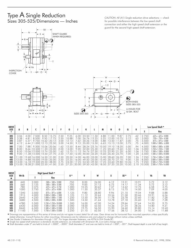
48 (131-110) © Rexnord Industries, LLC, 1998, 2006.
Type A Single ReductionSizes 305-525/Dimensions — Inches
DRIVESIZE
�
A B C D E F G J K L M N O Q RLow Speed Shaft �
S Key
305 3.06 4.00 7.500 8.50 15.75 2.50 9.25 6.00 23.50 11.50 4.88 11.00 9.87 2.75 .62 2.750 .625 x .625 x 4.000325 3.38 4.81 8.500 9.50 17.75 2.50 10.88 7.00 26.76 12.25 5.25 12.00 10.75 3.12 .63 3.000 .750 x .750 x 4.500345 3.87 5.37 9.750 10.62 20.12 3.00 12.13 7.62 30.26 14.00 5.88 13.50 11.87 3.00 .75 3.500 .875 x .875 x 5.000365 4.12 6.44 11.000 12.13 22.50 3.00 14.50 9.13 35.00 15.50 6.63 15.13 13.00 3.75 .75 4.000 1.000 x 1.000 x 6.000
385 7.00 7.88 9.300 10.06 20.06 1.62 12.50 8.44 28.24 23.76 10.50 19.10 18.20 5.00 .94 4.500 1.000 x 1.000 x 6.500405 8.00 8.66 10.500 11.20 23.00 2.00 14.00 9.20 32.00 25.30 11.25 20.60 19.60 5.50 1.06 5.000 1.250 x 1.250 x 7.500425 8.50 10.06 12.000 12.74 25.00 1.62 15.75 11.12 34.74 27.50 12.25 22.90 21.20 6.00 1.06 5.750 1.500 x 1.500 x 8.000445 9.00 11.38 14.000 14.50 27.70 2.50 17.50 12.00 40.00 32.20 14.60 26.30 23.70 7.00 1.20 6.500 1.500 x 1.500 x 10.000
465 11.00 12.68 16.000 16.50 31.00 2.50 20.50 14.00 46.00 33.00 15.00 28.60 26.20 7.00 1.26 7.250 1.750 x 1.500 x 11.000485 12.00 14.88 18.000 19.00 35.00 2.50 22.25 16.00 49.50 35.00 15.40 30.70 27.10 9.00 1.50 8.500 2.000 x 1.500 x 13.000505 13.00 16.18 19.500 20.50 38.00 2.75 24.00 17.25 53.50 39.50 17.25 33.60 29.80 10.26 1.75 9.250 2.500 x 1.750 x 14.000525 15.00 18.38 21.000 22.50 41.00 2.50 27.25 20.00 59.50 42.00 18.50 37.20 33.20 10.50 2.10 10.500 2.500 x 1.750 x 16.000
DRIVESIZE�
Wt-lbHigh Speed Shaft �
U � V W X XX � Y YA YBT Key
305 440 2.000 .500 x .500 x 3.000 .750 8.00 24.00 6.12 12.31 10.91 5.72 3.12325 560 2.125 .500 x .500 x 3.500 .750 9.00 27.13 6.75 14.17 11.34 5.72 3.12345 780 2.375 .625 x .625 x 3.750 1.000 10.25 30.62 7.37 14.62 12.75 6.58 3.75365 1000 2.750 .625 x .625 x 4.000 1.000 11.50 35.37 8.13 15.75 14.00 7.09 4.00
385 1340 3.500 .875 x .875 x 6.000 1.125 9.80 28.80 9.96 21.10 19.04 9.88 5.88405 1915 4.000 1.000 x 1.000 x 7.000 1.125 11.12 32.64 10.56 21.58 20.66 10.91 6.56425 2640 4.250 1.000 x 1.000 x 7.500 1.250 12.50 36.00 11.78 23.78 22.60 11.82 7.28445 3680 4.500 1.000 x 1.000 x 8.000 1.500 14.50 41.64 13.78 27.18 24.60 11.82 7.28
465 4780 5.500 1.250 x 1.250 x 10.000 1.500 16.00 47.00 14.24 29.66 27.64 14.20 9.75485 6430 6.000 1.500 x 1.500 x 11.000 2.000 18.00 52.50 14.36 31.24 28.26 14.80 9.31505 8440 6.500 1.500 x 1.500 x 12.000 2.250 19.75 56.50 15.90 34.60 30.80 15.14 10.40525 11100 7.500 1.750 x 1.500 x 13.000 2.250 21.10 62.50 17.56 38.12 34.00 16.24 11.88
� Drawings are representative of this series of drives and do not agree in exact detail for all sizes. Gear drives are for horizontal floor mounted operation unless specificallystated otherwise. Consult Factory for other mountings. Dimensions are for reference only and subject to change without notice unless certified.
� Use Grade 5 fasteners for diameters through 1.50”. For larger diameter fasteners, use ASTM A-354 Grade BC.� Single low speed shaft extension is standard; double extension, as indicated with dimension XX, is an extra charge option.� Shaft diameters under 3” are held to limits of +.0000”, –.0005”. Shaft diameters 3” and over are held to limits of +.000”, –.001”. Shaft keyseat depth is one-half of key height.
Y O
YA
T
SHAFT GUARD(WHEN REQUIRED)
XX
X
N
B
YB
S
INSPECTIONCOVER
A
CAUTION: All (A1) Single reduction drive selections — check
for possible interference between the low speed shaft
connection and either the high speed shaft extension or the
guard for the second high speed shaft extension.
R
Q Q
M M
L
E
V
SIZES 305-365
F
G G
K
J
F
6-HOLES FORDIA. BOLTU
BOTH ENDSSIZES 385-525
W
C D
1.2
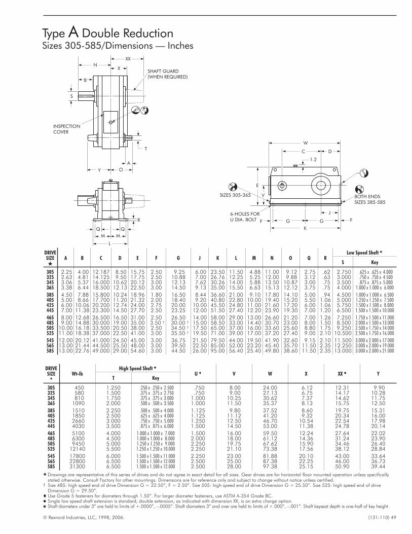
© Rexnord Industries, LLC, 1998, 2006. (131-110) 49
Type A Double ReductionSizes 305-585/Dimensions — Inches
DRIVESIZE�
A B C D E F G J K L M N O Q RLow Speed Shaft �
S Key
305 2.25 4.00 12.187 8.50 15.75 2.50 9.25 6.00 23.50 11.50 4.88 11.00 9.12 2.75 .62 2.750 .625 x .625 x 4.000325 2.63 4.81 14.125 9.50 17.75 2.50 10.88 7.00 26.76 12.25 5.25 12.00 9.88 3.12 .63 3.000 .750 x .750 x 4.500345 3.06 5.37 16.000 10.62 20.12 3.00 12.13 7.62 30.26 14.00 5.88 13.50 10.87 3.00 .75 3.500 .875 x .875 x 5.000365 3.38 6.44 18.500 12.13 22.50 3.00 14.50 9.13 35.00 15.50 6.63 15.13 12.12 3.75 .75 4.000 1.000 x 1.000 x 6.000
385 4.50 7.88 15.800 10.24 18.96 1.80 16.50 8.44 36.60 21.00 9.10 17.80 14.10 5.00 .94 4.500 1.000 x 1.000 x 6.500405 5.00 8.66 17.700 11.20 21.32 2.00 18.40 9.20 40.80 22.80 10.00 19.40 15.20 5.50 1.06 5.000 1.250 x 1.250 x 7.500425 6.00 10.06 20.200 12.74 24.00 2.75 20.00 10.00 45.50 24.80 11.00 21.60 17.20 6.00 1.06 5.750 1.500 x 1.500 x 8.000445 7.00 11.38 23.300 14.50 27.70 2.50 23.25 12.00 51.50 27.40 12.20 23.90 19.30 7.00 1.20 6.500 1.500 x 1.500 x 10.000
465 8.00 12.68 26.500 16.50 31.00 2.50 26.50 14.00 58.00 29.00 13.00 26.60 21.20 7.00 1.26 7.250 1.750 x 1.500 x 11.000485 9.00 14.88 30.000 19.00 35.00 3.50 † 30.00 † 15.00 58.50 33.00 14.40 30.70 23.00 8.00 1.50 8.500 2.000 x 1.500 x 13.000505 10.00 16.18 33.500 20.50 38.00 2.50 34.50 † 17.50 65.00 37.00 16.00 33.60 25.60 8.80 1.75 9.250 2.500 x 1.750 x 14.000525 11.00 18.38 37.000 22.50 41.00 3.00 35.50 † 19.50 71.00 39.00 17.00 37.20 27.40 9.00 2.10 10.500 2.500 x 1.750 x 16.000
545 12.00 20.12 41.000 24.50 45.00 3.00 36.75 21.50 79.50 44.00 19.50 41.90 32.60 9.15 2.10 11.500 3.000 x 2.000 x 17.000565 13.00 21.44 44.500 25.50 48.00 3.00 39.50 22.50 85.00 52.00 23.20 45.40 35.70 11.50 2.35 12.250 3.000 x 2.000 x 19.000585 13.00 22.76 49.000 29.00 54.60 3.00 44.50 26.00 95.00 56.40 25.40 49.80 38.60 11.50 2.35 13.000 3.000 x 2.000 x 21.000
DRIVESIZE
�
Wt-lbHigh Speed Shaft �
U � V W X XX � YT Key
305 450 1.250 .250 x .250 x 2.500 .750 8.00 24.00 6.12 12.31 9.90325 580 1.500 .375 x .375 x 2.750 .750 9.00 27.13 6.75 14.17 10.28345 810 1.750 .375 x .375 x 3.000 1.000 10.25 30.62 7.37 14.62 11.75365 1090 2.000 .500 x .500 x 3.500 1.000 11.50 35.37 8.13 15.75 12.50
385 1510 2.250 .500 x .500 x 4.000 1.125 9.80 37.52 8.60 19.75 15.31405 1850 2.500 .625 x .625 x 4.000 1.125 11.12 41.20 9.32 20.34 16.00425 2660 3.000 .750 x .750 x 5.000 1.250 12.50 46.70 10.54 22.54 17.98445 4030 3.500 .875 x .875 x 6.000 1.500 14.50 53.00 11.38 24.78 20.14
465 5100 4.000 1.000 x 1.000 x 7.000 1.500 16.00 59.50 12.24 27.64 22.02485 6300 4.500 1.000 x 1.000 x 8.000 2.000 18.00 61.12 14.36 31.24 23.90505 9450 5.000 1.250 x 1.250 x 9.000 2.250 19.75 67.62 15.90 34.46 26.40525 12140 5.500 1.250 x 1.250 x 10.000 2.250 21.10 73.38 17.56 38.12 28.84
545 17800 6.000 1.500 x 1.500 x 11.000 2.250 23.00 81.88 20.10 43.00 33.64565 22800 6.500 1.500 x 1.500 x 12.000 2.500 25.00 87.38 22.25 46.00 36.73585 31300 6.500 1.500 x 1.500 x 12.000 2.500 28.00 97.38 25.15 50.90 39.44
� Drawings are representative of this series of drives and do not agree in exact detail for all sizes. Gear drives are for horizontal floor mounted operation unless specificallystated otherwise. Consult Factory for other mountings. Dimensions are for reference only and subject to change without notice unless certified.
† Size 485: high speed end of drive Dimension G = 22.50”, F = 2.50”. Size 505: high speed end of drive Dimension G = 25.50”. Size 525: high speed end of driveDimension G = 29.50”.
� Use Grade 5 fasteners for diameters through 1.50”. For larger diameter fasteners, use ASTM A-354 Grade BC.� Single low speed shaft extension is standard; double extension, as indicated with dimension XX, is an extra charge option.� Shaft diameters under 3” are held to limits of +.0000”, –.0005”. Shaft diameters 3” and over are held to limits of +.000”, –.001”. Shaft keyseat depth is one-half of key height.
R
Q Q
M M
L
Y O
A
SHAFT GUARD(WHEN REQUIRED)
XX
X
N
B
S
INSPECTIONCOVER
T
E
VSIZES 305-365
F G G
K
J
F
6-HOLES FORU DIA. BOLT
BOTH ENDSSIZES 385-585
W
C D
1.2
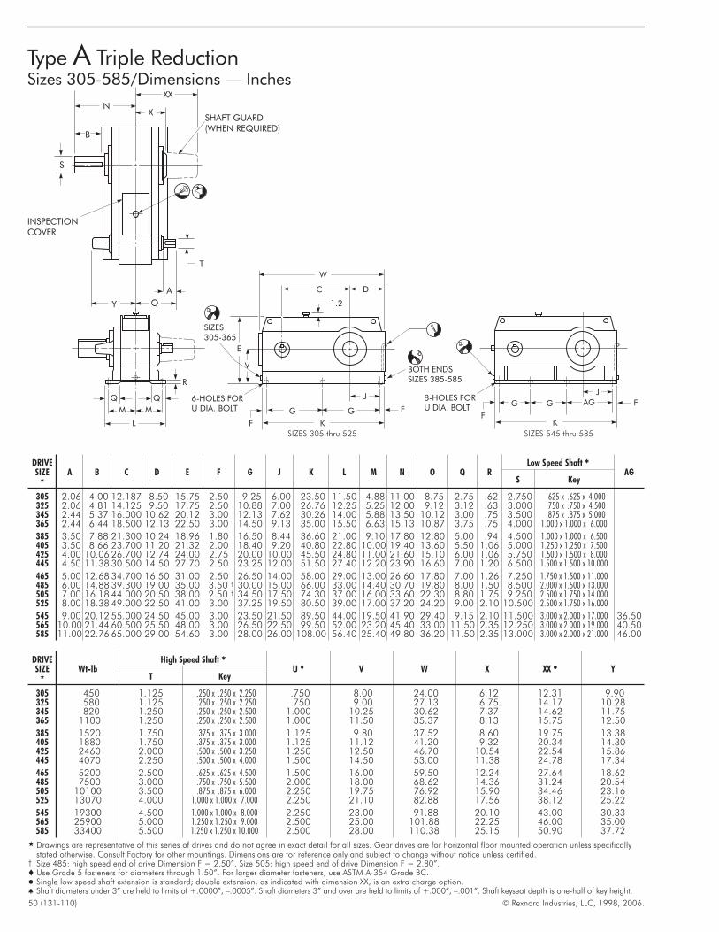
50 (131-110) © Rexnord Industries, LLC, 1998, 2006.
Type A Triple ReductionSizes 305-585/Dimensions — Inches
DRIVESIZE
H
A B C D E F G J K L M N O Q RLow Speed Shaft Q
AGS Key
305 2.06 4.00 12.187 8.50 15.75 2.50 9.25 6.00 23.50 11.50 4.88 11.00 8.75 2.75 .62 2.750 .625 x .625 x 4.000325 2.06 4.81 14.125 9.50 17.75 2.50 10.88 7.00 26.76 12.25 5.25 12.00 9.12 3.12 .63 3.000 .750 x .750 x 4.500345 2.44 5.37 16.000 10.62 20.12 3.00 12.13 7.62 30.26 14.00 5.88 13.50 10.12 3.00 .75 3.500 .875 x .875 x 5.000365 2.44 6.44 18.500 12.13 22.50 3.00 14.50 9.13 35.00 15.50 6.63 15.13 10.87 3.75 .75 4.000 1.000 x 1.000 x 6.000
385 3.50 7.88 21.300 10.24 18.96 1.80 16.50 8.44 36.60 21.00 9.10 17.80 12.80 5.00 .94 4.500 1.000 x 1.000 x 6.500405 3.50 8.66 23.700 11.20 21.32 2.00 18.40 9.20 40.80 22.80 10.00 19.40 13.60 5.50 1.06 5.000 1.250 x 1.250 x 7.500425 4.00 10.06 26.700 12.74 24.00 2.75 20.00 10.00 45.50 24.80 11.00 21.60 15.10 6.00 1.06 5.750 1.500 x 1.500 x 8.000445 4.50 11.38 30.500 14.50 27.70 2.50 23.25 12.00 51.50 27.40 12.20 23.90 16.60 7.00 1.20 6.500 1.500 x 1.500 x 10.000
465 5.00 12.68 34.700 16.50 31.00 2.50 26.50 14.00 58.00 29.00 13.00 26.60 17.80 7.00 1.26 7.250 1.750 x 1.500 x 11.000485 6.00 14.88 39.300 19.00 35.00 3.50 † 30.00 15.00 66.00 33.00 14.40 30.70 19.80 8.00 1.50 8.500 2.000 x 1.500 x 13.000505 7.00 16.18 44.000 20.50 38.00 2.50 † 34.50 17.50 74.30 37.00 16.00 33.60 22.30 8.80 1.75 9.250 2.500 x 1.750 x 14.000525 8.00 18.38 49.000 22.50 41.00 3.00 37.25 19.50 80.50 39.00 17.00 37.20 24.20 9.00 2.10 10.500 2.500 x 1.750 x 16.000
545 9.00 20.12 55.000 24.50 45.00 3.00 23.50 21.50 89.50 44.00 19.50 41.90 29.40 9.15 2.10 11.500 3.000 x 2.000 x 17.000 36.50565 10.00 21.44 60.500 25.50 48.00 3.00 26.50 22.50 99.50 52.00 23.20 45.40 33.00 11.50 2.35 12.250 3.000 x 2.000 x 19.000 40.50585 11.00 22.76 65.000 29.00 54.60 3.00 28.00 26.00 108.00 56.40 25.40 49.80 36.20 11.50 2.35 13.000 3.000 x 2.000 x 21.000 46.00
DRIVESIZE
H
Wt-lbHigh Speed Shaft Q
U � V W X XX � YT Key
305 450 1.125 .250 x .250 x 2.250 .750 8.00 24.00 6.12 12.31 9.90325 580 1.125 .250 x .250 x 2.250 .750 9.00 27.13 6.75 14.17 10.28345 820 1.250 .250 x .250 x 2.500 1.000 10.25 30.62 7.37 14.62 11.75365 1100 1.250 .250 x .250 x 2.500 1.000 11.50 35.37 8.13 15.75 12.50
385 1520 1.750 .375 x .375 x 3.000 1.125 9.80 37.52 8.60 19.75 13.38405 1880 1.750 .375 x .375 x 3.000 1.125 11.12 41.20 9.32 20.34 14.30425 2460 2.000 .500 x .500 x 3.250 1.250 12.50 46.70 10.54 22.54 15.86445 4070 2.250 .500 x .500 x 4.000 1.500 14.50 53.00 11.38 24.78 17.34
465 5200 2.500 .625 x .625 x 4.500 1.500 16.00 59.50 12.24 27.64 18.62485 7500 3.000 .750 x .750 x 5.500 2.000 18.00 68.62 14.36 31.24 20.54505 10100 3.500 .875 x .875 x 6.000 2.250 19.75 76.92 15.90 34.46 23.16525 13070 4.000 1.000 x 1.000 x 7.000 2.250 21.10 82.88 17.56 38.12 25.22
545 19300 4.500 1.000 x 1.000 x 8.000 2.250 23.00 91.88 20.10 43.00 30.33565 25900 5.000 1.250 x 1.250 x 9.000 2.500 25.00 101.88 22.25 46.00 35.00585 33400 5.500 1.250 x 1.250 x 10.000 2.500 28.00 110.38 25.15 50.90 37.72
H Drawings are representative of this series of drives and do not agree in exact detail for all sizes. Gear drives are for horizontal floor mounted operation unless specificallystated otherwise. Consult Factory for other mountings. Dimensions are for reference only and subject to change without notice unless certified.
† Size 485: high speed end of drive Dimension F = 2.50”. Size 505: high speed end of drive Dimension F = 2.80”.� Use Grade 5 fasteners for diameters through 1.50”. For larger diameter fasteners, use ASTM A-354 Grade BC.� Single low speed shaft extension is standard; double extension, as indicated with dimension XX, is an extra charge option.Q Shaft diameters under 3” are held to limits of +.0000”, –.0005”. Shaft diameters 3” and over are held to limits of +.000”, –.001”. Shaft keyseat depth is one-half of key height.
Y O
A
SHAFT GUARD(WHEN REQUIRED)
XX
X
N
B
S
INSPECTIONCOVER
T
E
V
SIZES305-365
F
G G
K
J
F
6-HOLES FORU DIA. BOLT
BOTH ENDSSIZES 385-585
W
C D
1.2
F
G G
K
J
F8-HOLES FORU DIA. BOLT
AG
R
Q Q
M M
L
SIZES 305 thru 525 SIZES 545 thru 585
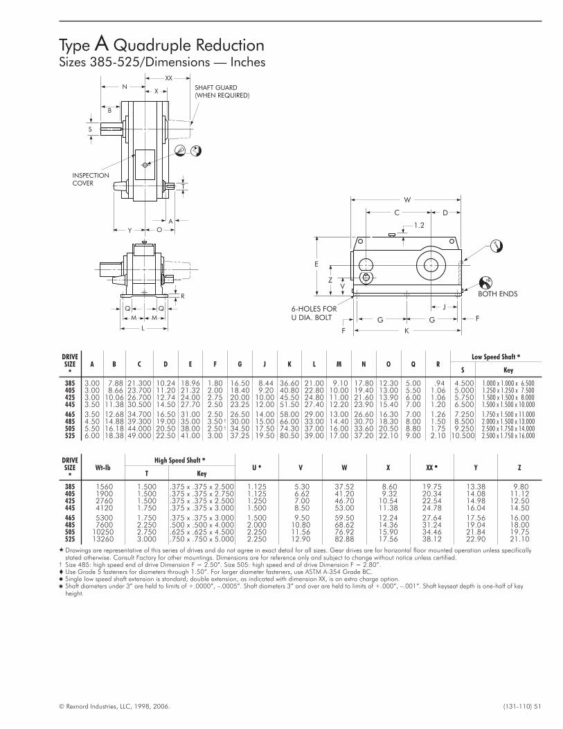
© Rexnord Industries, LLC, 1998, 2006. (131-110) 51
Type A Quadruple ReductionSizes 385-525/Dimensions — Inches
DRIVESIZE
�
A B C D E F G J K L M N O Q RLow Speed Shaft �
S Key
385 3.00 7.88 21.300 10.24 18.96 1.80 16.50 8.44 36.60 21.00 9.10 17.80 12.30 5.00 .94 4.500 1.000 x 1.000 x 6.500405 3.00 8.66 23.700 11.20 21.32 2.00 18.40 9.20 40.80 22.80 10.00 19.40 13.00 5.50 1.06 5.000 1.250 x 1.250 x 7.500425 3.00 10.06 26.700 12.74 24.00 2.75 20.00 10.00 45.50 24.80 11.00 21.60 13.90 6.00 1.06 5.750 1.500 x 1.500 x 8.000445 3.50 11.38 30.500 14.50 27.70 2.50 23.25 12.00 51.50 27.40 12.20 23.90 15.40 7.00 1.20 6.500 1.500 x 1.500 x 10.000
465 3.50 12.68 34.700 16.50 31.00 2.50 26.50 14.00 58.00 29.00 13.00 26.60 16.30 7.00 1.26 7.250 1.750 x 1.500 x 11.000485 4.50 14.88 39.300 19.00 35.00 3.50 † 30.00 15.00 66.00 33.00 14.40 30.70 18.30 8.00 1.50 8.500 2.000 x 1.500 x 13.000505 5.50 16.18 44.000 20.50 38.00 2.50 † 34.50 17.50 74.30 37.00 16.00 33.60 20.50 8.80 1.75 9.250 2.500 x 1.750 x 14.000525 6.00 18.38 49.000 22.50 41.00 3.00 37.25 19.50 80.50 39.00 17.00 37.20 22.10 9.00 2.10 10.500 2.500 x 1.750 x 16.000
DRIVESIZE
�
Wt-lbHigh Speed Shaft �
U � V W X XX � Y ZT Key
385 1560 1.500 .375 x .375 x 2.500 1.125 5.30 37.52 8.60 19.75 13.38 9.80405 1900 1.500 .375 x .375 x 2.750 1.125 6.62 41.20 9.32 20.34 14.08 11.12425 2760 1.500 .375 x .375 x 2.500 1.250 7.00 46.70 10.54 22.54 14.98 12.50445 4120 1.750 .375 x .375 x 3.000 1.500 8.50 53.00 11.38 24.78 16.04 14.50
465 5300 1.750 .375 x .375 x 3.000 1.500 9.50 59.50 12.24 27.64 17.56 16.00485 7600 2.250 .500 x .500 x 4.000 2.000 10.80 68.62 14.36 31.24 19.04 18.00505 10250 2.750 .625 x .625 x 4.500 2.250 11.56 76.92 15.90 34.46 21.84 19.75525 13260 3.000 .750 x .750 x 5.000 2.250 12.90 82.88 17.56 38.12 22.90 21.10
� Drawings are representative of this series of drives and do not agree in exact detail for all sizes. Gear drives are for horizontal floor mounted operation unless specificallystated otherwise. Consult Factory for other mountings. Dimensions are for reference only and subject to change without notice unless certified.
† Size 485: high speed end of drive Dimension F = 2.50”. Size 505: high speed end of drive Dimension F = 2.80”.� Use Grade 5 fasteners for diameters through 1.50”. For larger diameter fasteners, use ASTM A-354 Grade BC.� Single low speed shaft extension is standard; double extension, as indicated with dimension XX, is an extra charge option.� Shaft diameters under 3” are held to limits of +.0000”, –.0005”. Shaft diameters 3” and over are held to limits of +.000”, –.001”. Shaft keyseat depth is one-half of key
height.
R
Q Q
M M
L
Y O
A
SHAFT GUARD(WHEN REQUIRED)
XX
XN
B
S
INSPECTIONCOVER
T
E
V
F
G G
K
J
F
6-HOLES FORU DIA. BOLT
BOTH ENDS
W
C D
1.2
Z
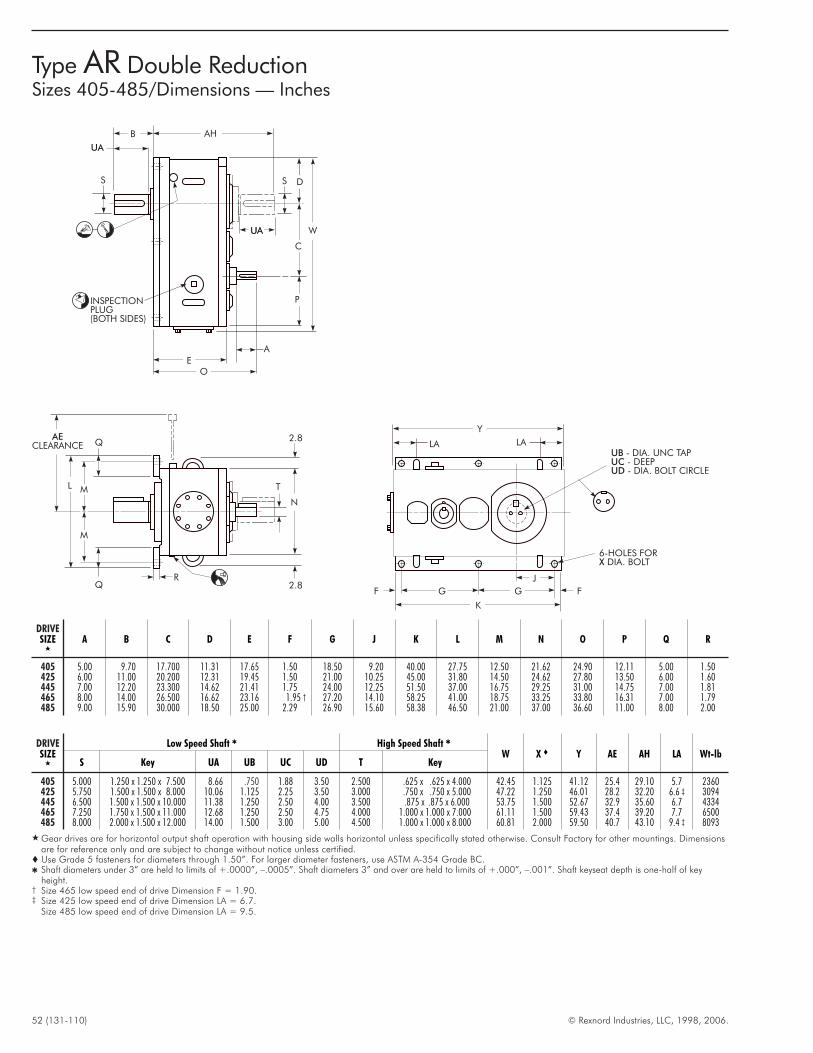
52 (131-110) © Rexnord Industries, LLC, 1998, 2006.
Type AR Double ReductionSizes 405-485/Dimensions — Inches
DRIVESIZE
�
A B C D E F G J K L M N O P Q R
405 5.00 9.70 17.700 11.31 17.65 1.50 18.50 9.20 40.00 27.75 12.50 21.62 24.90 12.11 5.00 1.50425 6.00 11.00 20.200 12.31 19.45 1.50 21.00 10.25 45.00 31.80 14.50 24.62 27.80 13.50 6.00 1.60445 7.00 12.20 23.300 14.62 21.41 1.75 24.00 12.25 51.50 37.00 16.75 29.25 31.00 14.75 7.00 1.81465 8.00 14.00 26.500 16.62 23.16 1.95 † 27.20 14.10 58.25 41.00 18.75 33.25 33.80 16.31 7.00 1.79485 9.00 15.90 30.000 18.50 25.00 2.29 26.90 15.60 58.38 46.50 21.00 37.00 36.60 11.00 8.00 2.00
DRIVESIZE
�
Low Speed Shaft � High Speed Shaft �
W X � Y AE AH LA Wt-lbS Key UA UB UC UD T Key
405 5.000 1.250 x 1.250 x 7.500 8.66 .750 1.88 3.50 2.500 .625 x .625 x 4.000 42.45 1.125 41.12 25.4 29.10 5.7 2360425 5.750 1.500 x 1.500 x 8.000 10.06 1.125 2.25 3.50 3.000 .750 x .750 x 5.000 47.22 1.250 46.01 28.2 32.20 6.6 ‡ 3094445 6.500 1.500 x 1.500 x 10.000 11.38 1.250 2.50 4.00 3.500 .875 x .875 x 6.000 53.75 1.500 52.67 32.9 35.60 6.7 4334465 7.250 1.750 x 1.500 x 11.000 12.68 1.250 2.50 4.75 4.000 1.000 x 1.000 x 7.000 61.11 1.500 59.43 37.4 39.20 7.7 6500485 8.000 2.000 x 1.500 x 12.000 14.00 1.500 3.00 5.00 4.500 1.000 x 1.000 x 8.000 60.81 2.000 59.50 40.7 43.10 9.4 ‡ 8093
� Gear drives are for horizontal output shaft operation with housing side walls horizontal unless specifically stated otherwise. Consult Factory for other mountings. Dimensionsare for reference only and are subject to change without notice unless certified.
� Use Grade 5 fasteners for diameters through 1.50”. For larger diameter fasteners, use ASTM A-354 Grade BC.� Shaft diameters under 3” are held to limits of +.0000”, –.0005”. Shaft diameters 3” and over are held to limits of +.000”, –.001”. Shaft keyseat depth is one-half of key
height.† Size 465 low speed end of drive Dimension F = 1.90.‡ Size 425 low speed end of drive Dimension LA = 6.7.
Size 485 low speed end of drive Dimension LA = 9.5.
LA LA
Y
G GF F
K
J
6-HOLES FORDIA. BOLTX
2.8
2.8
N
T
R
Q
Q
M
ML
AECLEARANCE
P
EO
UA
C
D
W
AHB
SS
UBUCUD
- DIA. UNC TAP- DEEP- DIA. BOLT CIRCLE
INSPECTIONPLUG(BOTH SIDES)
UA
UA
A
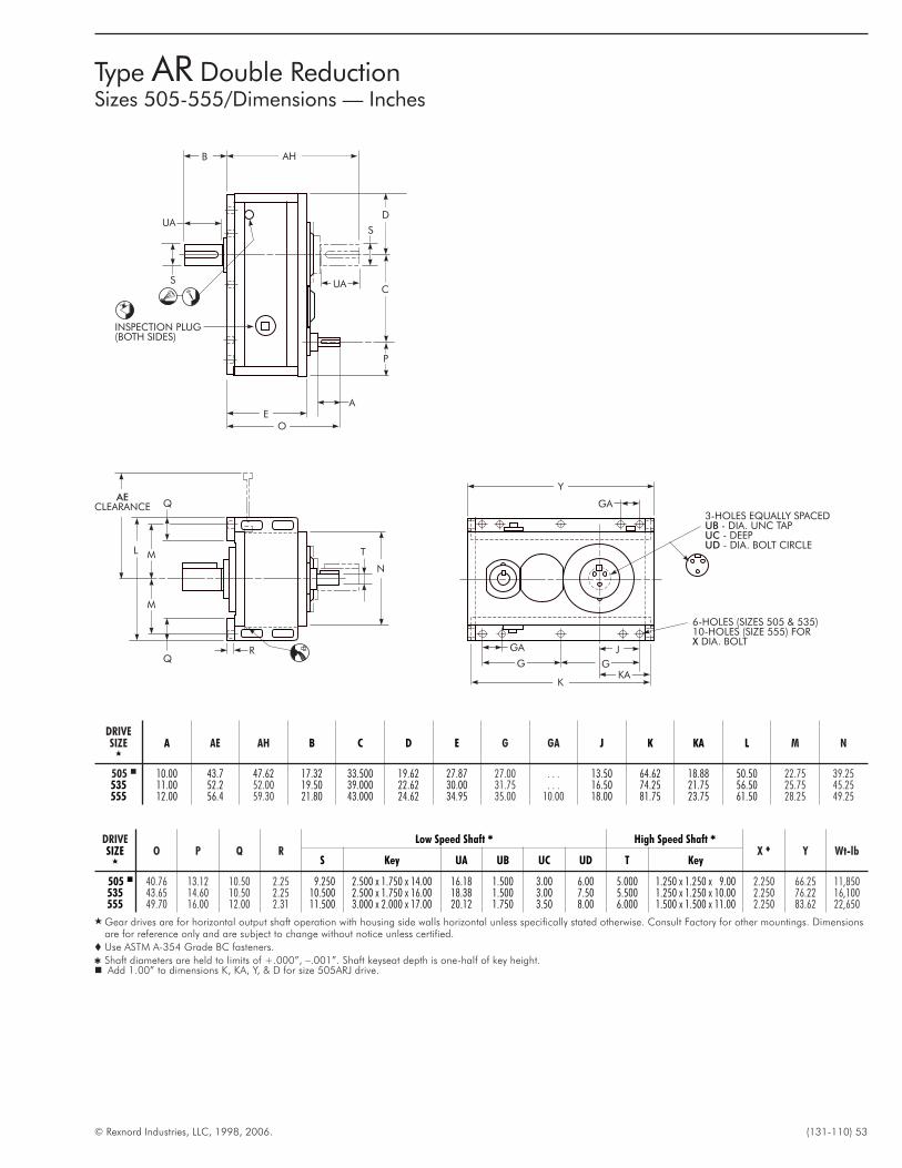
© Rexnord Industries, LLC, 1998, 2006. (131-110) 53
DRIVESIZE
�
O P Q RLow Speed Shaft � High Speed Shaft �
X � Y Wt-lbS Key UA UB UC UD T Key
505 � 40.76 13.12 10.50 2.25 9.250 2.500 x 1.750 x 14.00 16.18 1.500 3.00 6.00 5.000 1.250 x 1.250 x 9.00 2.250 66.25 11,850535 43.65 14.60 10.50 2.25 10.500 2.500 x 1.750 x 16.00 18.38 1.500 3.00 7.50 5.500 1.250 x 1.250 x 10.00 2.250 76.22 16,100555 49.70 16.00 12.00 2.31 11.500 3.000 x 2.000 x 17.00 20.12 1.750 3.50 8.00 6.000 1.500 x 1.500 x 11.00 2.250 83.62 22,650
� Gear drives are for horizontal output shaft operation with housing side walls horizontal unless specifically stated otherwise. Consult Factory for other mountings. Dimensionsare for reference only and are subject to change without notice unless certified.
� Use ASTM A-354 Grade BC fasteners.
� Shaft diameters are held to limits of +.000”, –.001”. Shaft keyseat depth is one-half of key height.� Add 1.00” to dimensions K, KA, Y, & D for size 505ARJ drive.
DRIVESIZE
�
A AE AH B C D E G GA J K KA L M N
505 � 10.00 43.7 47.62 17.32 33.500 19.62 27.87 27.00 . . . 13.50 64.62 18.88 50.50 22.75 39.25535 11.00 52.2 52.00 19.50 39.000 22.62 30.00 31.75 . . . 16.50 74.25 21.75 56.50 25.75 45.25555 12.00 56.4 59.30 21.80 43.000 24.62 34.95 35.00 10.00 18.00 81.75 23.75 61.50 28.25 49.25
Y
G
GA
G
K
6-HOLES (SIZES 505 & 535)10-HOLES (SIZE 555) FOR
DIA. BOLTX
N
T
R
Q
Q
M
ML
AECLEARANCE
P
EO
UAC
D
AHB
S
S
3-HOLES EQUALLY SPACED- DIA. UNC TAP- DEEP- DIA. BOLT CIRCLE
UBUCUD
GA
KA
INSPECTION PLUG(BOTH SIDES)
J
UA
A
Type AR Double ReductionSizes 505-555/Dimensions — Inches
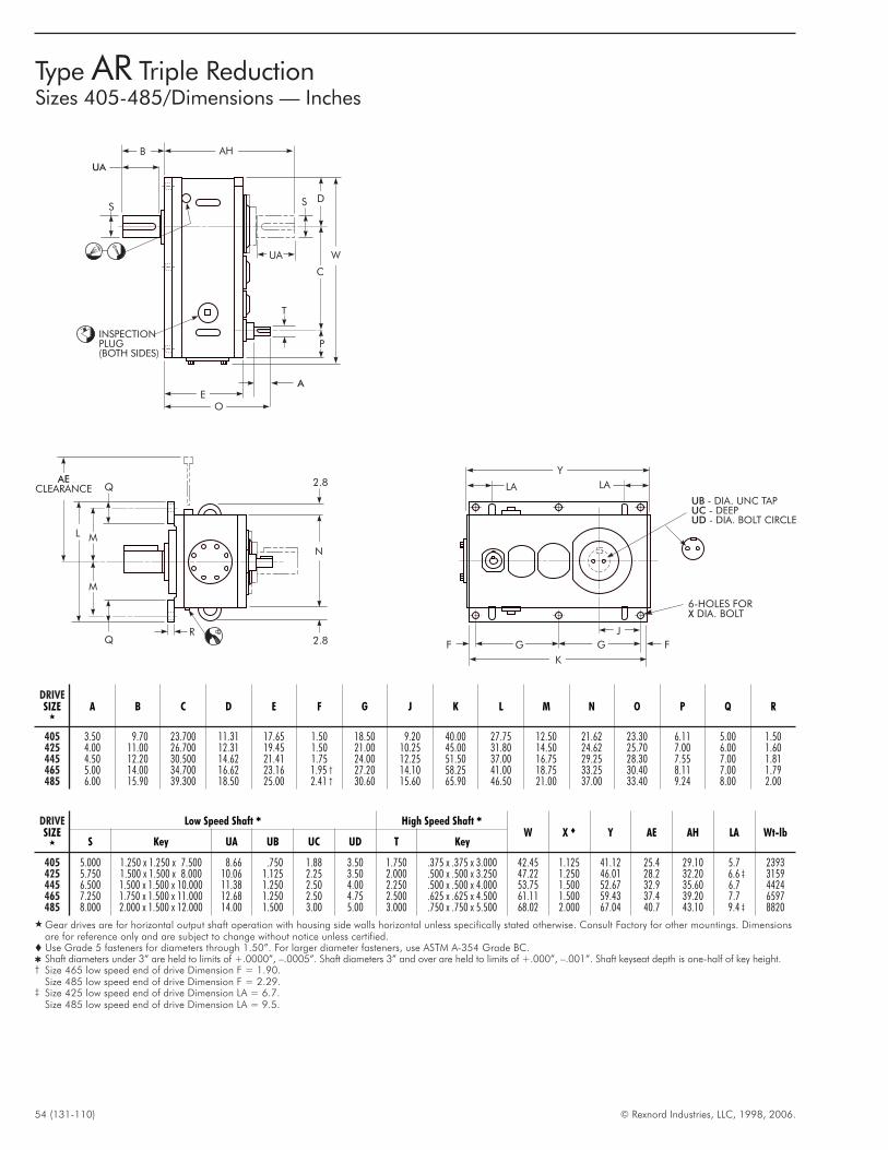
54 (131-110) © Rexnord Industries, LLC, 1998, 2006.
Type AR Triple ReductionSizes 405-485/Dimensions — Inches
DRIVESIZE
�
A B C D E F G J K L M N O P Q R
405 3.50 9.70 23.700 11.31 17.65 1.50 18.50 9.20 40.00 27.75 12.50 21.62 23.30 6.11 5.00 1.50425 4.00 11.00 26.700 12.31 19.45 1.50 21.00 10.25 45.00 31.80 14.50 24.62 25.70 7.00 6.00 1.60445 4.50 12.20 30.500 14.62 21.41 1.75 24.00 12.25 51.50 37.00 16.75 29.25 28.30 7.55 7.00 1.81465 5.00 14.00 34.700 16.62 23.16 1.95 † 27.20 14.10 58.25 41.00 18.75 33.25 30.40 8.11 7.00 1.79485 6.00 15.90 39.300 18.50 25.00 2.41 † 30.60 15.60 65.90 46.50 21.00 37.00 33.40 9.24 8.00 2.00
DRIVESIZE
�
Low Speed Shaft � High Speed Shaft �
W X � Y AE AH LA Wt-lbS Key UA UB UC UD T Key
405 5.000 1.250 x 1.250 x 7.500 8.66 .750 1.88 3.50 1.750 .375 x .375 x 3.000 42.45 1.125 41.12 25.4 29.10 5.7 2393425 5.750 1.500 x 1.500 x 8.000 10.06 1.125 2.25 3.50 2.000 .500 x .500 x 3.250 47.22 1.250 46.01 28.2 32.20 6.6 ‡ 3159445 6.500 1.500 x 1.500 x 10.000 11.38 1.250 2.50 4.00 2.250 .500 x .500 x 4.000 53.75 1.500 52.67 32.9 35.60 6.7 4424465 7.250 1.750 x 1.500 x 11.000 12.68 1.250 2.50 4.75 2.500 .625 x .625 x 4.500 61.11 1.500 59.43 37.4 39.20 7.7 6597485 8.000 2.000 x 1.500 x 12.000 14.00 1.500 3.00 5.00 3.000 .750 x .750 x 5.500 68.02 2.000 67.04 40.7 43.10 9.4 ‡ 8820
� Gear drives are for horizontal output shaft operation with housing side walls horizontal unless specifically stated otherwise. Consult Factory for other mountings. Dimensionsare for reference only and are subject to change without notice unless certified.
� Use Grade 5 fasteners for diameters through 1.50”. For larger diameter fasteners, use ASTM A-354 Grade BC.� Shaft diameters under 3” are held to limits of +.0000”, –.0005”. Shaft diameters 3” and over are held to limits of +.000”, –.001”. Shaft keyseat depth is one-half of key height.† Size 465 low speed end of drive Dimension F = 1.90.
Size 485 low speed end of drive Dimension F = 2.29.‡ Size 425 low speed end of drive Dimension LA = 6.7.
Size 485 low speed end of drive Dimension LA = 9.5.
LA LA
Y
G GF F
K
J
6-HOLES FORDIA. BOLTX
2.8
2.8
N
R
Q
Q
M
ML
AECLEARANCE
UBUCUD
- DIA. UNC TAP- DEEP- DIA. BOLT CIRCLE
P
AE
O
UA
C
D
W
AHB
S
UA
S
T
INSPECTIONPLUG(BOTH SIDES)
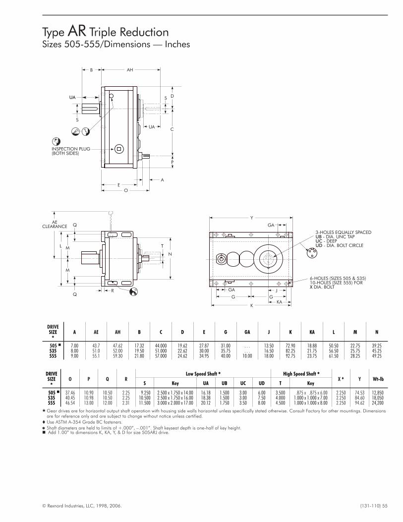
© Rexnord Industries, LLC, 1998, 2006. (131-110) 55
Type AR Triple ReductionSizes 505-555/Dimensions — Inches
DRIVESIZE
�
O P Q RLow Speed Shaft � High Speed Shaft �
X � Y Wt-lbS Key UA UB UC UD T Key
505 � 37.46 10.90 10.50 2.25 9.250 2.500 x 1.750 x 14.00 16.18 1.500 3.00 6.00 3.500 .875 x .875 x 6.00 2.250 74.53 12,850535 40.45 10.98 10.50 2.25 10.500 2.500 x 1.750 x 16.00 18.38 1.500 3.00 7.50 4.000 1.000 x 1.000 x 7.00 2.250 84.60 18,050555 46.54 13.00 12.00 2.31 11.500 3.000 x 2.000 x 17.00 20.12 1.750 3.50 8.00 4.500 1.000 x 1.000 x 8.00 2.250 94.62 24,200
� Gear drives are for horizontal output shaft operation with housing side walls horizontal unless specifically stated otherwise. Consult Factory for other mountings. Dimensionsare for reference only and are subject to change without notice unless certified.
� Use ASTM A-354 Grade BC fasteners.
� Shaft diameters are held to limits of +.000”, –.001”. Shaft keyseat depth is one-half of key height.� Add 1.00” to dimensions K, KA, Y, & D for size 505ARJ drive.
DRIVESIZE
�
A AE AH B C D E G GA J K KA L M N
505 � 7.00 43.7 47.62 17.32 44.000 19.62 27.87 31.00 . . . 13.50 72.90 18.88 50.50 22.75 39.25535 8.00 51.0 52.00 19.50 51.000 22.62 30.00 35.75 . . . 16.50 82.25 21.75 56.50 25.75 45.25555 9.00 55.1 59.30 21.80 57.000 24.62 34.95 40.00 10.00 18.00 92.75 23.75 61.50 28.25 49.25
T
G
GA
G
J
P
AE
O
UAC
D
AHB
S
SUA
3-HOLES EQUALLY SPACED- DIA. UNC TAP- DEEP- DIA. BOLT CIRCLE
UBUCUD
KA
N
R
Q
Q
M
ML
AECLEARANCE GA
K
6-HOLES (SIZES 505 & 535)10-HOLES (SIZE 555) FOR
DIA. BOLTX
Y
INSPECTION PLUG(BOTH SIDES)
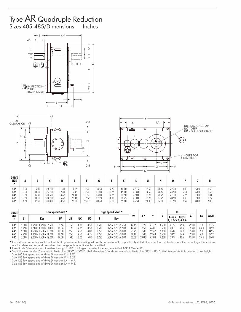
56 (131-110) © Rexnord Industries, LLC, 1998, 2006.
Type AR Quadruple ReductionSizes 405-485/Dimensions — Inches
LA LA
Y
G GF F
K
J
6-HOLES FORDIA. BOLTX
UBUCUD
- DIA. UNC TAP- DEEP- DIA. BOLT CIRCLE
2.8
2.8
N
T
R
Q
Q
M
ML
AECLEARANCE
P
AE
O
UA
C
D
W
AHB
S
UA
S
Z
INSPECTIONPLUG(BOTH SIDES)
DRIVESIZE
�
A B C D E F G J K L M N O P Q R
405 3.00 9.70 23.700 11.31 17.65 1.50 18.50 9.20 40.00 27.75 12.50 21.62 22.70 6.11 5.00 1.50425 3.00 11.00 26.700 12.31 19.45 1.50 21.00 10.25 45.00 31.80 14.50 24.62 24.50 7.00 6.00 1.60445 3.50 12.20 30.500 14.62 21.41 1.75 24.00 12.25 51.50 37.00 16.75 29.25 27.10 7.55 7.00 1.81465 3.50 14.00 34.700 16.62 23.16 1.95 † 27.20 14.10 58.25 41.00 18.75 33.25 28.90 8.11 7.00 1.79485 4.50 15.90 39.300 18.50 25.00 2.41 † 30.60 15.60 65.90 46.50 21.00 37.00 31.90 9.24 8.00 2.00
DRIVESIZE
�
Low Speed Shaft � High Speed Shaft �
W X � Y Z
AE
AH LA Wt-lbS Key UA UB UC UD T Key
Assy’s1, 3 & 5
Assy’s2, 4 & 6
405 5.000 1.250 x 1.250 x 7.500 8.66 .750 1.88 3.50 1.500 .375 x .375 x 2.750 42.45 1.125 41.12 4.500 21.5 25.4 29.10 5.7 2375425 5.750 1.500 x 1.500 x 8.000 10.06 1.125 2.25 3.50 1.500 .375 x .375 x 2.500 47.22 1.250 46.01 5.500 23.1 28.2 32.20 6.6 ‡ 3159445 6.500 1.500 x 1.500 x 10.000 11.38 1.250 2.50 4.00 1.750 .375 x .375 x 3.000 53.75 1.500 52.67 6.000 26.8 32.9 35.60 6.7 4495465 7.250 1.750 x 1.500 x 11.000 12.68 1.250 2.50 4.75 1.750 .375 x .375 x 3.000 61.11 1.500 59.43 6.500 30.9 37.4 39.20 7.7 6752485 8.000 2.000 x 1.500 x 12.000 14.00 1.500 3.00 5.00 2.250 .500 x .500 x 4.000 68.02 2.000 67.04 7.200 33.3 40.7 43.10 9.4 ‡ 8960
� Gear drives are for horizontal output shaft operation with housing side walls horizontal unless specifically stated otherwise. Consult Factory for other mountings. Dimensionsare for reference only and are subject to change without notice unless certified.
� Use Grade 5 fasteners for diameters through 1.50”. For larger diameter fasteners, use ASTM A-354 Grade BC.� Shaft diameters under 3” are held to limits of +.0000”, –.0005”. Shaft diameters 3” and over are held to limits of +.000”, –.001”. Shaft keyseat depth is one-half of key height.† Size 465 low speed end of drive Dimension F = 1.90.
Size 485 low speed end of drive Dimension F = 2.29.‡ Size 425 low speed end of drive Dimension LA = 6.7.
Size 485 low speed end of drive Dimension LA = 9.5.
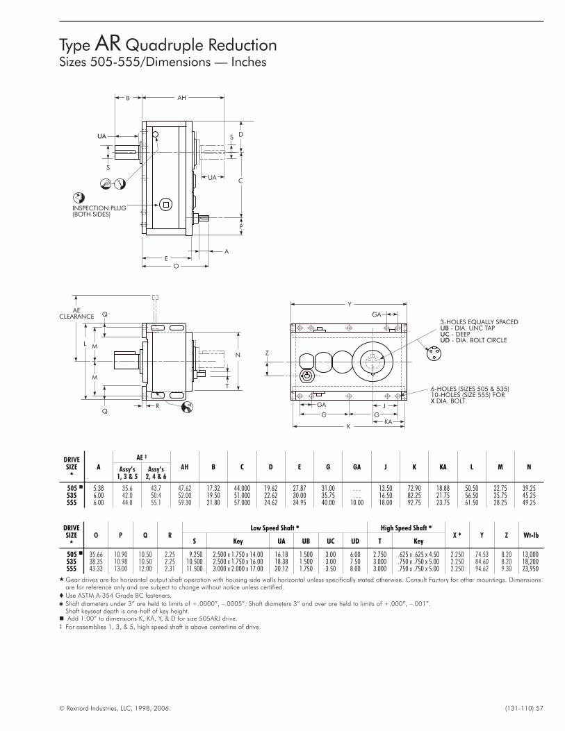
© Rexnord Industries, LLC, 1998, 2006. (131-110) 57
DRIVESIZE
�
O P Q RLow Speed Shaft � High Speed Shaft �
X � Y Z Wt-lbS Key UA UB UC UD T Key
505 � 35.66 10.90 10.50 2.25 9.250 2.500 x 1.750 x 14.00 16.18 1.500 3.00 6.00 2.750 .625 x .625 x 4.50 2.250 74.53 8.20 13,000535 38.35 10.98 10.50 2.25 10.500 2.500 x 1.750 x 16.00 18.38 1.500 3.00 7.50 3.000 .750 x .750 x 5.00 2.250 84.60 8.20 18,200555 43.33 13.00 12.00 2.31 11.500 3.000 x 2.000 x 17.00 20.12 1.750 3.50 8.00 3.000 .750 x .750 x 5.00 2.250 94.62 9.30 23,950
� Gear drives are for horizontal output shaft operation with housing side walls horizontal unless specifically stated otherwise. Consult Factory for other mountings. Dimensionsare for reference only and are subject to change without notice unless certified.
� Use ASTM A-354 Grade BC fasteners.
� Shaft diameters under 3” are held to limits of +.0000”, –.0005”. Shaft diameters 3” and over are held to limits of +.000”, –.001”.Shaft keyseat depth is one-half of key height.� Add 1.00” to dimensions K, KA, Y, & D for size 505ARJ drive.‡ For assemblies 1, 3, & 5, high speed shaft is above centerline of drive.
DRIVESIZE
�
A
AE ‡
AH B C D E G GA J K KA L M NAssy’s1, 3 & 5
Assy’s2, 4 & 6
505 � 5.38 35.6 43.7 47.62 17.32 44.000 19.62 27.87 31.00 . . . 13.50 72.90 18.88 50.50 22.75 39.25535 6.00 42.0 50.4 52.00 19.50 51.000 22.62 30.00 35.75 . . . 16.50 82.25 21.75 56.50 25.75 45.25555 6.00 44.8 55.1 59.30 21.80 57.000 24.62 34.95 40.00 10.00 18.00 92.75 23.75 61.50 28.25 49.25
Y
G
GA
G
K
J
6-HOLES (SIZES 505 & 535)10-HOLES (SIZE 555) FOR
DIA. BOLTX
P
AE
O
UAC
D
AHB
S
SUA
KA
N
R
Q
Q
M
ML
AECLEARANCE
T
Z
3-HOLES EQUALLY SPACED- DIA. UNC TAP- DEEP- DIA. BOLT CIRCLE
UBUCUD
GA
INSPECTION PLUG(BOTH SIDES)
Type AR Quadruple ReductionSizes 505-555/Dimensions — Inches
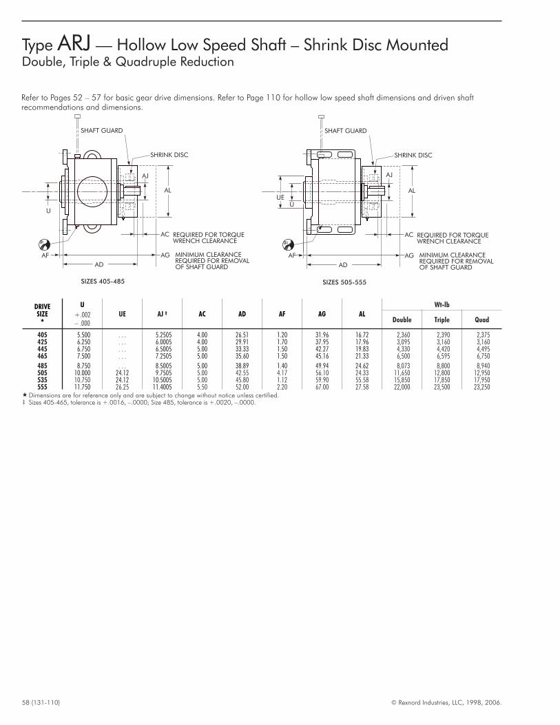
58 (131-110) © Rexnord Industries, LLC, 1998, 2006.
Type ARJ — Hollow Low Speed Shaft – Shrink Disc MountedDouble, Triple & Quadruple Reduction
U
AF
AD
AC
AG
REQUIRED FOR TORQUEWRENCH CLEARANCE
MINIMUM CLEARANCEREQUIRED FOR REMOVALOF SHAFT GUARD
AL
SHAFT GUARD
SHRINK DISC
AJ
SIZES 405-485
DRIVESIZE
�
U
+.002– .000
UE AJ ‡ AC AD AF AG AL
Wt-lb
Double Triple Quad
405 5.500 . . . 5.2505 4.00 26.51 1.20 31.96 16.72 2,360 2,390 2,375425 6.250 . . . 6.0005 4.00 29.91 1.70 37.95 17.96 3,095 3,160 3,160445 6.750 . . . 6.5005 5.00 33.33 1.50 42.27 19.83 4,330 4,420 4,495465 7.500 . . . 7.2505 5.00 35.60 1.50 45.16 21.33 6,500 6,595 6,750
485 8.750 . . . 8.5005 5.00 38.89 1.40 49.94 24.62 8,073 8,800 8,940505 10.000 24.12 9.7505 5.00 42.55 4.17 56.10 24.33 11,650 12,800 12,950535 10.750 24.12 10.5005 5.00 45.80 1.12 59.90 55.58 15,850 17,850 17,950555 11.750 26.25 11.4005 5.50 52.00 2.20 67.00 27.58 22,000 23,500 23,250
� Dimensions are for reference only and are subject to change without notice unless certified.‡ Sizes 405-465, tolerance is +.0016, –.0000; Size 485, tolerance is +.0020, –.0000.
Refer to Pages 52 – 57 for basic gear drive dimensions. Refer to Page 110 for hollow low speed shaft dimensions and driven shaftrecommendations and dimensions.
U
AF
AD
AC
AG
REQUIRED FOR TORQUEWRENCH CLEARANCE
MINIMUM CLEARANCEREQUIRED FOR REMOVALOF SHAFT GUARD
ALUE
SHAFT GUARD
SHRINK DISC
AJ
SIZES 505-555
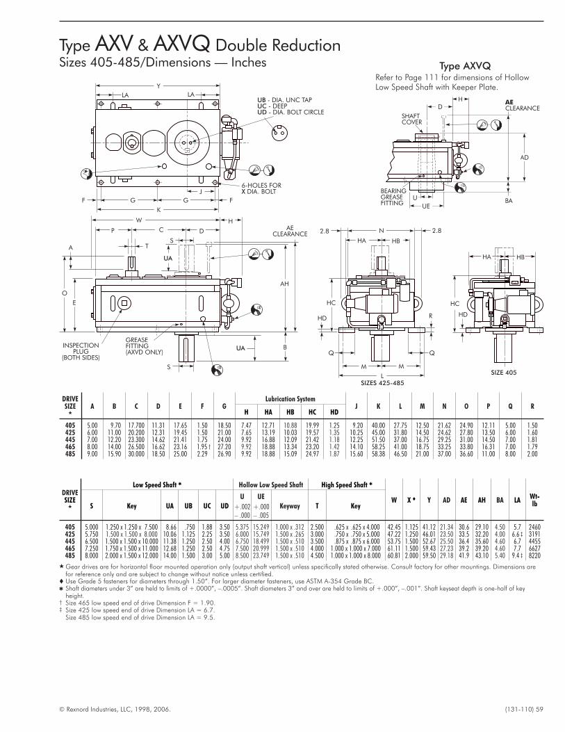
© Rexnord Industries, LLC, 1998, 2006. (131-110) 59
Type AXV & AXVQ Double ReductionSizes 405-485/Dimensions — Inches
SIZE 405
N 2.82.8
HA HB
HC
HD R
MM
L
UA
UA B
AH
GREASEFITTING(AXVD ONLY)
INSPECTIONPLUG
(BOTH SIDES)
S
E
O
A T
P C D
S
W H
F FGG
K
J
Y
LA LAUBUCUD
- DIA. UNC TAP- DEEP- DIA. BOLT CIRCLE
6-HOLES FORDIA. BOLTX
AECLEARANCE
HC
HD
HBHA
SIZES 425-485
DRIVESIZE
�
A B C D E F GLubrication System
J K L M N O P Q RH HA HB HC HD
405 5.00 9.70 17.700 11.31 17.65 1.50 18.50 7.47 12.71 10.88 19.99 1.25 9.20 40.00 27.75 12.50 21.62 24.90 12.11 5.00 1.50425 6.00 11.00 20.200 12.31 19.45 1.50 21.00 7.65 13.19 10.03 19.57 1.35 10.25 45.00 31.80 14.50 24.62 27.80 13.50 6.00 1.60445 7.00 12.20 23.300 14.62 21.41 1.75 24.00 9.92 16.88 12.09 21.42 1.18 12.25 51.50 37.00 16.75 29.25 31.00 14.50 7.00 1.81465 8.00 14.00 26.500 16.62 23.16 1.95 † 27.20 9.92 18.88 13.34 23.20 1.42 14.10 58.25 41.00 18.75 33.25 33.80 16.31 7.00 1.79485 9.00 15.90 30.000 18.50 25.00 2.29 26.90 9.92 18.88 15.09 24.97 1.87 15.60 58.38 46.50 21.00 37.00 36.60 11.00 8.00 2.00
DRIVESIZE
�
Low Speed Shaft � Hollow Low Speed Shaft High Speed Shaft �
W X � Y AD AE AH BA LAWt-lbS Key UA UB UC UD
U
+.002– .000
UE
+.000– .005
Keyway T Key
405 5.000 1.250 x 1.250 x 7.500 8.66 .750 1.88 3.50 5.375 15.249 1.000 x .312 2.500 .625 x .625 x 4.000 42.45 1.125 41.12 21.34 30.6 29.10 4.50 5.7 2460425 5.750 1.500 x 1.500 x 8.000 10.06 1.125 2.25 3.50 6.000 15.749 1.500 x .265 3.000 .750 x .750 x 5.000 47.22 1.250 46.01 23.50 33.5 32.20 4.00 6.6 ‡ 3191445 6.500 1.500 x 1.500 x 10.000 11.38 1.250 2.50 4.00 6.750 18.499 1.500 x .510 3.500 .875 x .875 x 6.000 53.75 1.500 52.67 25.50 36.4 35.60 4.60 6.7 4455465 7.250 1.750 x 1.500 x 11.000 12.68 1.250 2.50 4.75 7.500 20.999 1.500 x .510 4.000 1.000 x 1.000 x 7.000 61.11 1.500 59.43 27.23 39.2 39.20 4.60 7.7 6627485 8.000 2.000 x 1.500 x 12.000 14.00 1.500 3.00 5.00 8.500 23.749 1.500 x .510 4.500 1.000 x 1.000 x 8.000 60.81 2.000 59.50 29.18 41.9 43.10 5.40 9.4 ‡ 8220
� Gear drives are for horizontal floor mounted operation only (output shaft vertical) unless specifically stated otherwise. Consult factory for other mountings. Dimensions arefor reference only and are subject to change without notice unless certified.
� Use Grade 5 fasteners for diameters through 1.50”. For larger diameter fasteners, use ASTM A-354 Grade BC.� Shaft diameters under 3” are held to limits of +.0000”, –.0005”. Shaft diameters 3” and over are held to limits of +.000”, –.001”. Shaft keyseat depth is one-half of key
height.† Size 465 low speed end of drive Dimension F = 1.90.‡ Size 425 low speed end of drive Dimension LA = 6.7.
Size 485 low speed end of drive Dimension LA = 9.5.
HD
BEARINGGREASEFITTING
AE
CLEARANCE
SHAFTCOVER
AD
UEBAU
Type AXVQRefer to Page 111 for dimensions of HollowLow Speed Shaft with Keeper Plate.
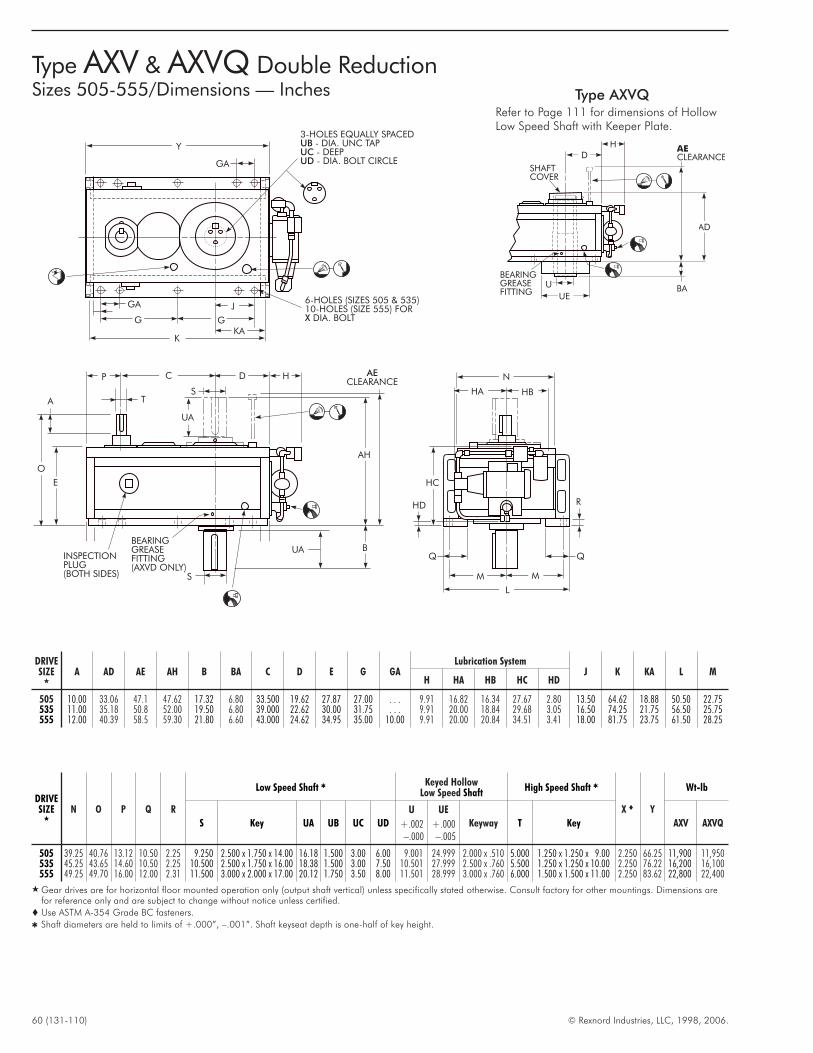
60 (131-110) © Rexnord Industries, LLC, 1998, 2006.
DRIVESIZE
�
N O P Q R
Low Speed Shaft � Keyed HollowLow Speed Shaft
High Speed Shaft �
X � Y
Wt-lb
S Key UA UB UC UD
U
+.002–.000
UE
+.000–.005
Keyway T Key AXV AXVQ
505 39.25 40.76 13.12 10.50 2.25 9.250 2.500 x 1.750 x 14.00 16.18 1.500 3.00 6.00 9.001 24.999 2.000 x .510 5.000 1.250 x 1.250 x 9.00 2.250 66.25 11,900 11,950535 45.25 43.65 14.60 10.50 2.25 10.500 2.500 x 1.750 x 16.00 18.38 1.500 3.00 7.50 10.501 27.999 2.500 x .760 5.500 1.250 x 1.250 x 10.00 2.250 76.22 16,200 16,100555 49.25 49.70 16.00 12.00 2.31 11.500 3.000 x 2.000 x 17.00 20.12 1.750 3.50 8.00 11.501 28.999 3.000 x .760 6.000 1.500 x 1.500 x 11.00 2.250 83.62 22,800 22,400
� Gear drives are for horizontal floor mounted operation only (output shaft vertical) unless specifically stated otherwise. Consult factory for other mountings. Dimensions arefor reference only and are subject to change without notice unless certified.
� Use ASTM A-354 Grade BC fasteners.
� Shaft diameters are held to limits of +.000”, –.001”. Shaft keyseat depth is one-half of key height.
DRIVESIZE
�
A AD AE AH B BA C D E G GALubrication System
J K KA L MH HA HB HC HD
505 10.00 33.06 47.1 47.62 17.32 6.80 33.500 19.62 27.87 27.00 . . . 9.91 16.82 16.34 27.67 2.80 13.50 64.62 18.88 50.50 22.75535 11.00 35.18 50.8 52.00 19.50 6.80 39.000 22.62 30.00 31.75 . . . 9.91 20.00 18.84 29.68 3.05 16.50 74.25 21.75 56.50 25.75555 12.00 40.39 58.5 59.30 21.80 6.60 43.000 24.62 34.95 35.00 10.00 9.91 20.00 20.84 34.51 3.41 18.00 81.75 23.75 61.50 28.25
N
HA HB
HC
HD R
MM
L
UA
UA B
AH
BEARINGGREASEFITTING(AXVD ONLY)
INSPECTIONPLUG(BOTH SIDES) S
E
O
A T
P C D
S
H
Y
G
GA
G
K
J6-HOLES (SIZES 505 & 535)10-HOLES (SIZE 555) FOR
DIA. BOLTX
3-HOLES EQUALLY SPACED- DIA. UNC TAP- DEEP- DIA. BOLT CIRCLE
UBUCUD
KA
AECLEARANCE
GA
HD
BEARINGGREASEFITTING
AE
CLEARANCE
SHAFTCOVER
AD
UEBAU
Type AXV & AXVQ Double ReductionSizes 505-555/Dimensions — Inches Type AXVQ
Refer to Page 111 for dimensions of HollowLow Speed Shaft with Keeper Plate.
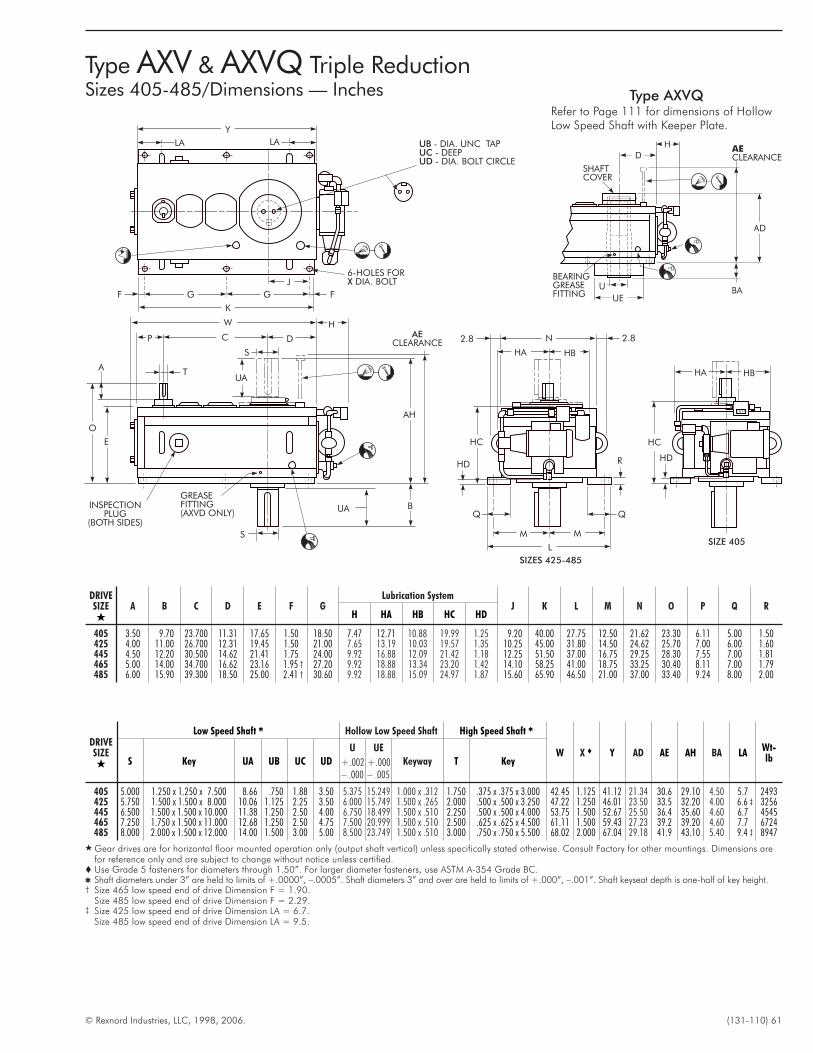
© Rexnord Industries, LLC, 1998, 2006. (131-110) 61
N 2.82.8
HA HB
HC
HD R
MM
L
UA
UA B
AH
GREASEFITTING(AXVD ONLY)
INSPECTIONPLUG
(BOTH SIDES)
S
E
O
AT
P C D
S
W H
F FGG
K
J
Y
LA LA UBUCUD
- DIA. UNC TAP- DEEP- DIA. BOLT CIRCLE
6-HOLES FORDIA. BOLTX
AECLEARANCE
SIZE 405
HC
HD
HBHA
SIZES 425-485
DRIVESIZE�
A B C D E F GLubrication System
J K L M N O P Q RH HA HB HC HD
405 3.50 9.70 23.700 11.31 17.65 1.50 18.50 7.47 12.71 10.88 19.99 1.25 9.20 40.00 27.75 12.50 21.62 23.30 6.11 5.00 1.50425 4.00 11.00 26.700 12.31 19.45 1.50 21.00 7.65 13.19 10.03 19.57 1.35 10.25 45.00 31.80 14.50 24.62 25.70 7.00 6.00 1.60445 4.50 12.20 30.500 14.62 21.41 1.75 24.00 9.92 16.88 12.09 21.42 1.18 12.25 51.50 37.00 16.75 29.25 28.30 7.55 7.00 1.81465 5.00 14.00 34.700 16.62 23.16 1.95 † 27.20 9.92 18.88 13.34 23.20 1.42 14.10 58.25 41.00 18.75 33.25 30.40 8.11 7.00 1.79485 6.00 15.90 39.300 18.50 25.00 2.41 † 30.60 9.92 18.88 15.09 24.97 1.87 15.60 65.90 46.50 21.00 37.00 33.40 9.24 8.00 2.00
DRIVESIZE�
Low Speed Shaft � Hollow Low Speed Shaft High Speed Shaft �
W X � Y AD AE AH BA LAWt-lbS Key UA UB UC UD
U
+.002– .000
UE
+.000– .005
Keyway T Key
405 5.000 1.250 x 1.250 x 7.500 8.66 .750 1.88 3.50 5.375 15.249 1.000 x .312 1.750 .375 x .375 x 3.000 42.45 1.125 41.12 21.34 30.6 29.10 4.50 5.7 2493425 5.750 1.500 x 1.500 x 8.000 10.06 1.125 2.25 3.50 6.000 15.749 1.500 x .265 2.000 .500 x .500 x 3.250 47.22 1.250 46.01 23.50 33.5 32.20 4.00 6.6 ‡ 3256445 6.500 1.500 x 1.500 x 10.000 11.38 1.250 2.50 4.00 6.750 18.499 1.500 x .510 2.250 .500 x .500 x 4.000 53.75 1.500 52.67 25.50 36.4 35.60 4.60 6.7 4545465 7.250 1.750 x 1.500 x 11.000 12.68 1.250 2.50 4.75 7.500 20.999 1.500 x .510 2.500 .625 x .625 x 4.500 61.11 1.500 59.43 27.23 39.2 39.20 4.60 7.7 6724485 8.000 2.000 x 1.500 x 12.000 14.00 1.500 3.00 5.00 8.500 23.749 1.500 x .510 3.000 .750 x .750 x 5.500 68.02 2.000 67.04 29.18 41.9 43.10 5.40 9.4 ‡ 8947
� Gear drives are for horizontal floor mounted operation only (output shaft vertical) unless specifically stated otherwise. Consult Factory for other mountings. Dimensions arefor reference only and are subject to change without notice unless certified.
� Use Grade 5 fasteners for diameters through 1.50”. For larger diameter fasteners, use ASTM A-354 Grade BC.� Shaft diameters under 3” are held to limits of +.0000”, –.0005”. Shaft diameters 3” and over are held to limits of +.000”, –.001”. Shaft keyseat depth is one-half of key height.† Size 465 low speed end of drive Dimension F = 1.90.
Size 485 low speed end of drive Dimension F = 2.29.‡ Size 425 low speed end of drive Dimension LA = 6.7.
Size 485 low speed end of drive Dimension LA = 9.5.
Type AXV & AXVQ Triple ReductionSizes 405-485/Dimensions — Inches
HD
BEARINGGREASEFITTING
AE
CLEARANCE
SHAFTCOVER
AD
UEBAU
Type AXVQRefer to Page 111 for dimensions of HollowLow Speed Shaft with Keeper Plate.
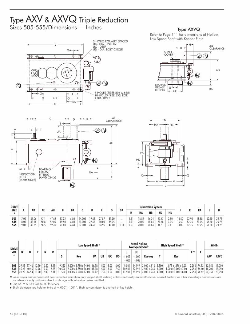
62 (131-110) © Rexnord Industries, LLC, 1998, 2006.
DRIVESIZE
�
N O P Q R
Low Speed Shaft � Keyed HollowLow Speed Shaft
High Speed Shaft �
X � Y
Wt-lb
S Key UA UB UC UD
U
+.002–.000
UE
+.000–.005
Keyway T Key AXV AXVQ
505 39.25 37.46 10.90 10.50 2.25 9.250 2.500 x 1.750 x 14.00 16.18 1.500 3.00 6.00 9.001 24.999 2.000 x .510 3.500 .875 x .875 x 6.00 2.250 74.53 12,950 13,000535 45.25 40.45 10.98 10.50 2.25 10.500 2.500 x 1.750 x 16.00 18.38 1.500 3.00 7.50 10.501 27.999 2.500 x .760 4.000 1.000 x 1.000 x 7.00 2.250 84.60 18,200 18,050555 49.25 46.54 13.00 12.00 2.31 11.500 3.000 x 2.000 x 17.00 20.12 1.750 3.50 8.00 11.501 28.999 3.000 x .760 4.500 1.000 x 1.000 x 8.00 2.250 94.62 24,350 23,950
� Gear drives are for horizontal floor mounted operation only (output shaft vertical) unless specifically stated otherwise. Consult Factory for other mountings. Dimensions arefor reference only and are subject to change without notice unless certified.
� Use ASTM A-354 Grade BC fasteners.
� Shaft diameters are held to limits of +.000”, –.001”. Shaft keyseat depth is one-half of key height.
DRIVESIZE
�
A AD AE AH B BA C D E G GALubrication System
J K KA L MH HA HB HC HD
505 7.00 33.06 47.1 47.62 17.32 6.80 44.000 19.62 27.87 31.00 . . . 9.91 16.82 16.34 27.67 2.80 13.50 72.90 18.88 50.50 22.75535 8.00 35.18 50.8 52.00 19.50 6.80 51.000 22.62 30.00 35.75 . . . 9.91 20.00 18.84 29.68 3.05 16.50 82.25 21.75 56.50 25.75555 9.00 40.39 58.5 59.30 21.80 6.60 57.000 24.62 34.95 40.00 10.00 9.91 20.00 20.84 34.51 3.41 18.00 92.75 23.75 61.50 28.25
N
HA HB
HC
HD R
MM
L
UA
UA B
AH
BEARINGGREASEFITTING(AXVD ONLY)
S
EO
A
P C D
S
H
Y
G
GA
G
K
J6-HOLES (SIZES 505 & 535)10-HOLES (SIZE 555) FORX DIA. BOLT
3-HOLES EQUALLY SPACEDUB - DIA. UNC TAPUC - DEEPUD - DIA. BOLT CIRCLE
KA
AECLEARANCE
LA
T
GA
INSPECTIONPLUG(BOTH SIDES)
Type AXV & AXVQ Triple ReductionSizes 505-555/Dimensions — Inches
HD
BEARINGGREASEFITTING
AE
CLEARANCE
SHAFTCOVER
AD
UEBAU
Type AXVQRefer to Page 111 for dimensions of HollowLow Speed Shaft with Keeper Plate.
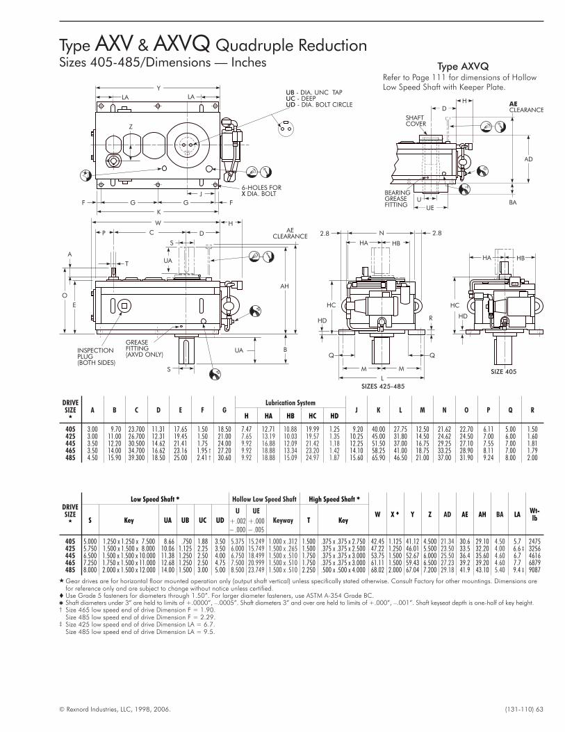
© Rexnord Industries, LLC, 1998, 2006. (131-110) 63
N 2.82.8
HA HB
HC
HD R
MM
L
UA
UA B
AH
GREASEFITTING(AXVD ONLY)
INSPECTIONPLUG(BOTH SIDES)
S
E
O
A
T
P C D
S
W H
F FGG
K
J
Y
LA LAUBUCUD
- DIA. UNC TAP- DEEP- DIA. BOLT CIRCLE
6-HOLES FORDIA. BOLTX
AECLEARANCE
Z
SIZE 405
HC
HD
HBHA
SIZES 425-485
DRIVESIZE
�
Low Speed Shaft � Hollow Low Speed Shaft High Speed Shaft �
W X � Y Z AD AE AH BA LAWt-lbS Key UA UB UC UD
U
+.002– .000
UE
+.000– .005
Keyway T Key
405 5.000 1.250 x 1.250 x 7.500 8.66 .750 1.88 3.50 5.375 15.249 1.000 x .312 1.500 .375 x .375 x 2.750 42.45 1.125 41.12 4.500 21.34 30.6 29.10 4.50 5.7 2475425 5.750 1.500 x 1.500 x 8.000 10.06 1.125 2.25 3.50 6.000 15.749 1.500 x .265 1.500 .375 x .375 x 2.500 47.22 1.250 46.01 5.500 23.50 33.5 32.20 4.00 6.6 ‡ 3256445 6.500 1.500 x 1.500 x 10.000 11.38 1.250 2.50 4.00 6.750 18.499 1.500 x .510 1.750 .375 x .375 x 3.000 53.75 1.500 52.67 6.000 25.50 36.4 35.60 4.60 6.7 4616465 7.250 1.750 x 1.500 x 11.000 12.68 1.250 2.50 4.75 7.500 20.999 1.500 x .510 1.750 .375 x .375 x 3.000 61.11 1.500 59.43 6.500 27.23 39.2 39.20 4.60 7.7 6879485 8.000 2.000 x 1.500 x 12.000 14.00 1.500 3.00 5.00 8.500 23.749 1.500 x .510 2.250 .500 x .500 x 4.000 68.02 2.000 67.04 7.200 29.18 41.9 43.10 5.40 9.4 ‡ 9087
� Gear drives are for horizontal floor mounted operation only (output shaft vertical) unless specifically stated otherwise. Consult Factory for other mountings. Dimensions arefor reference only and are subject to change without notice unless certified.
� Use Grade 5 fasteners for diameters through 1.50”. For larger diameter fasteners, use ASTM A-354 Grade BC.� Shaft diameters under 3” are held to limits of +.0000”, –.0005”. Shaft diameters 3” and over are held to limits of +.000”, –.001”. Shaft keyseat depth is one-half of key height.† Size 465 low speed end of drive Dimension F = 1.90.
Size 485 low speed end of drive Dimension F = 2.29.‡ Size 425 low speed end of drive Dimension LA = 6.7.
Size 485 low speed end of drive Dimension LA = 9.5.
DRIVESIZE
�
A B C D E F GLubrication System
J K L M N O P Q RH HA HB HC HD
405 3.00 9.70 23.700 11.31 17.65 1.50 18.50 7.47 12.71 10.88 19.99 1.25 9.20 40.00 27.75 12.50 21.62 22.70 6.11 5.00 1.50425 3.00 11.00 26.700 12.31 19.45 1.50 21.00 7.65 13.19 10.03 19.57 1.35 10.25 45.00 31.80 14.50 24.62 24.50 7.00 6.00 1.60445 3.50 12.20 30.500 14.62 21.41 1.75 24.00 9.92 16.88 12.09 21.42 1.18 12.25 51.50 37.00 16.75 29.25 27.10 7.55 7.00 1.81465 3.50 14.00 34.700 16.62 23.16 1.95 † 27.20 9.92 18.88 13.34 23.20 1.42 14.10 58.25 41.00 18.75 33.25 28.90 8.11 7.00 1.79485 4.50 15.90 39.300 18.50 25.00 2.41 † 30.60 9.92 18.88 15.09 24.97 1.87 15.60 65.90 46.50 21.00 37.00 31.90 9.24 8.00 2.00
Type AXV & AXVQ Quadruple ReductionSizes 405-485/Dimensions — Inches
HD
BEARINGGREASEFITTING
AE
CLEARANCE
SHAFTCOVER
AD
UEBAU
Type AXVQRefer to Page 111 for dimensions of HollowLow Speed Shaft with Keeper Plate.
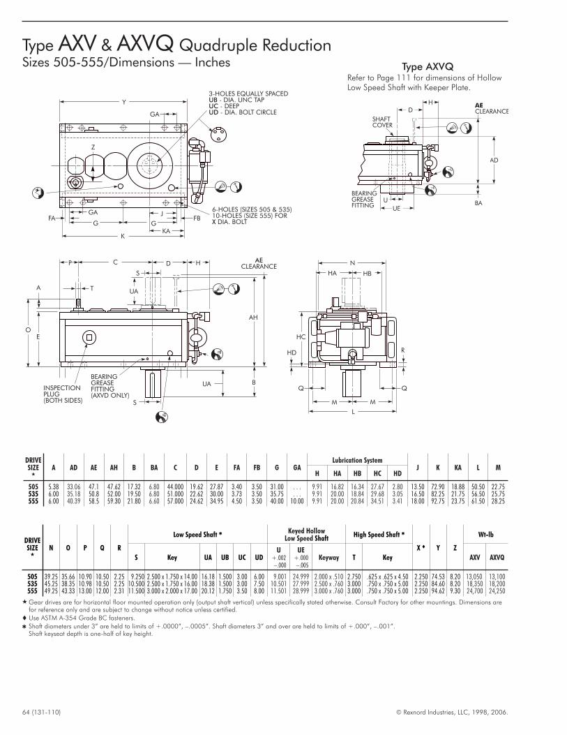
64 (131-110) © Rexnord Industries, LLC, 1998, 2006.
DRIVESIZE
�
N O P Q R
Low Speed Shaft � Keyed HollowLow Speed Shaft
High Speed Shaft �
X � Y Z
Wt-lb
S Key UA UB UC UDU
+.002–.000
UE+.000–.005
Keyway T Key AXV AXVQ
505 39.25 35.66 10.90 10.50 2.25 9.250 2.500 x 1.750 x 14.00 16.18 1.500 3.00 6.00 9.001 24.999 2.000 x .510 2.750 .625 x .625 x 4.50 2.250 74.53 8.20 13,050 13,100535 45.25 38.35 10.98 10.50 2.25 10.500 2.500 x 1.750 x 16.00 18.38 1.500 3.00 7.50 10.501 27.999 2.500 x .760 3.000 .750 x .750 x 5.00 2.250 84.60 8.20 18,350 18,200555 49.25 43.33 13.00 12.00 2.31 11.500 3.000 x 2.000 x 17.00 20.12 1.750 3.50 8.00 11.501 28.999 3.000 x .760 3.000 .750 x .750 x 5.00 2.250 94.62 9.30 24,700 24,250
� Gear drives are for horizontal floor mounted operation only (output shaft vertical) unless specifically stated otherwise. Consult Factory for other mountings. Dimensions arefor reference only and are subject to change without notice unless certified.
� Use ASTM A-354 Grade BC fasteners.
� Shaft diameters under 3” are held to limits of +.0000”, –.0005”. Shaft diameters 3” and over are held to limits of +.000”, –.001”.Shaft keyseat depth is one-half of key height.
DRIVESIZE
�
A AD AE AH B BA C D E FA FB G GALubrication System
J K KA L MH HA HB HC HD
505 5.38 33.06 47.1 47.62 17.32 6.80 44.000 19.62 27.87 3.40 3.50 31.00 . . . 9.91 16.82 16.34 27.67 2.80 13.50 72.90 18.88 50.50 22.75535 6.00 35.18 50.8 52.00 19.50 6.80 51.000 22.62 30.00 3.73 3.50 35.75 . . . 9.91 20.00 18.84 29.68 3.05 16.50 82.25 21.75 56.50 25.75555 6.00 40.39 58.5 59.30 21.80 6.60 57.000 24.62 34.95 4.50 3.50 40.00 10.00 9.91 20.00 20.84 34.51 3.41 18.00 92.75 23.75 61.50 28.25
N
HA HB
HC
HD R
MM
L
UA
UA B
AH
BEARINGGREASEFITTING(AXVD ONLY)
S
EO
A
P C D
S
H
Y
G
GA
G
K
J6-HOLES (SIZES 505 & 535)10-HOLES (SIZE 555) FOR
DIA. BOLTX
KA
AECLEARANCE
T
Z
3-HOLES EQUALLY SPACED- DIA. UNC TAP- DEEP- DIA. BOLT CIRCLE
UBUCUDGA
INSPECTIONPLUG(BOTH SIDES)
FBFA
Type AXV & AXVQ Quadruple ReductionSizes 505-555/Dimensions — Inches
HD
BEARINGGREASEFITTING
AE
CLEARANCE
SHAFTCOVER
AD
UEBAU
Type AXVQRefer to Page 111 for dimensions of HollowLow Speed Shaft with Keeper Plate.
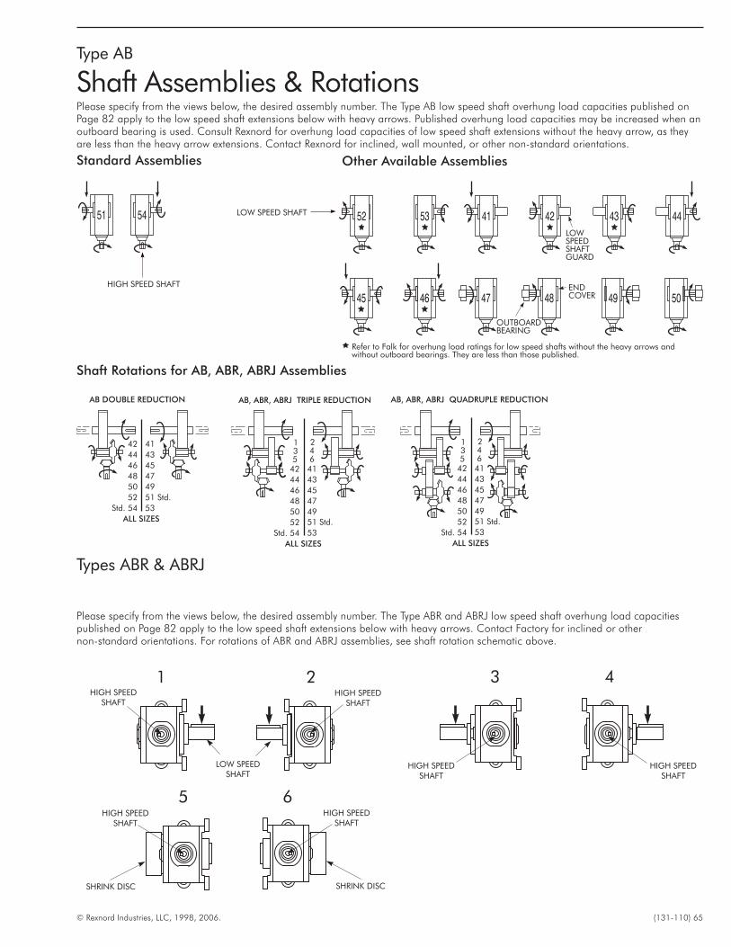
© Rexnord Industries, LLC, 1998, 2006. (131-110) 65
Type AB
Shaft Assemblies & RotationsPlease specify from the views below, the desired assembly number. The Type AB low speed shaft overhung load capacities published onPage 82 apply to the low speed shaft extensions below with heavy arrows. Published overhung load capacities may be increased when anoutboard bearing is used. Consult Rexnord for overhung load capacities of low speed shaft extensions without the heavy arrow, as theyare less than the heavy arrow extensions. Contact Rexnord for inclined, wall mounted, or other non-standard orientations.
AB DOUBLE REDUCTION AB, ABR, ABRJ QUADRUPLE REDUCTIONAB, ABR, ABRJ TRIPLE REDUCTION
ALL SIZES
4142
4344
4546
4748
51 Std.
50
53
52
Std. 54
OUTBOARDBEARING
ENDCOVER
LOWSPEEDSHAFTGUARD
Refer to Falk for overhung load ratings for low speed shafts without the heavy arrows andwithout outboard bearings. They are less than those published.
HIGH SPEED SHAFT
LOW SPEED SHAFT
49
ALL SIZES
4142
4344
4546
4748
49
51 Std.
50
53
52
Std. 54
5 6
1 23 4
ALL SIZES
4142
4344
4546
4748
49
51 Std.
50
53
52
Std. 54
5 6
1 23 4
Standard Assemblies Other Available Assemblies
Shaft Rotations for AB, ABR, ABRJ Assemblies
Types ABR & ABRJ
HIGH SPEEDSHAFT
HIGH SPEEDSHAFT
HIGH SPEEDSHAFT
HIGH SPEEDSHAFT
LOW SPEEDSHAFT
1
HIGH SPEEDSHAFT
HIGH SPEEDSHAFT
SHRINK DISC SHRINK DISC
5 6
2 3 4
Please specify from the views below, the desired assembly number. The Type ABR and ABRJ low speed shaft overhung load capacitiespublished on Page 82 apply to the low speed shaft extensions below with heavy arrows. Contact Factory for inclined or othernon-standard orientations. For rotations of ABR and ABRJ assemblies, see shaft rotation schematic above.
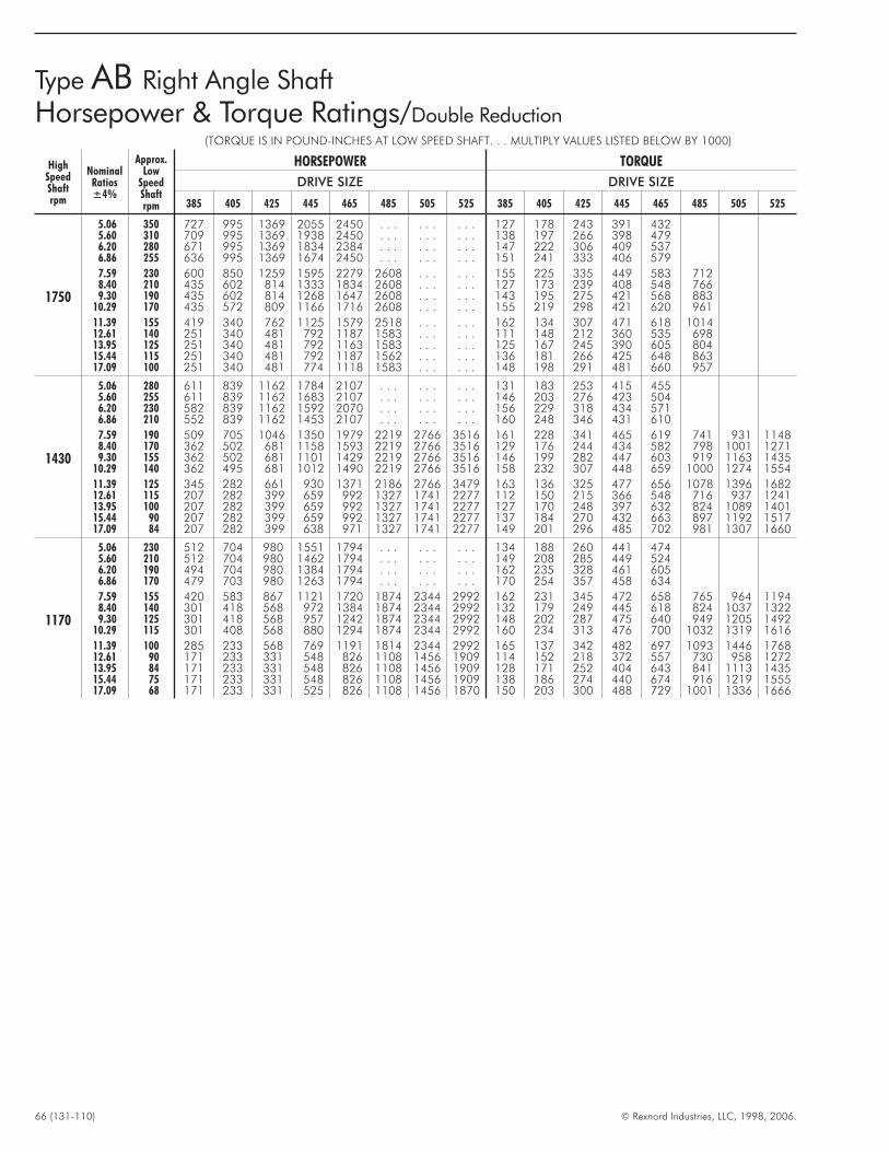
66 (131-110) © Rexnord Industries, LLC, 1998, 2006.
(TORQUE IS IN POUND-INCHES AT LOW SPEED SHAFT. . . MULTIPLY VALUES LISTED BELOW BY 1000)
HighSpeedShaftrpm
NominalRatios±4%
Approx.Low
SpeedShaftrpm
HORSEPOWER TORQUE
DRIVE SIZE DRIVE SIZE
385 405 425 445 465 485 505 525 385 405 425 445 465 485 505 525
1750
5.06 350 727 995 1369 2055 2450 . . . . . . . . . 127 178 243 391 4325.60 310 709 995 1369 1938 2450 . . . . . . . . . 138 197 266 398 4796.20 280 671 995 1369 1834 2384 . . . . . . . . . 147 222 306 409 5376.86 255 636 995 1369 1674 2450 . . . . . . . . . 151 241 333 406 579
7.59 230 600 850 1259 1595 2279 2608 . . . . . . 155 225 335 449 583 7128.40 210 435 602 814 1333 1834 2608 . . . . . . 127 173 239 408 548 7669.30 190 435 602 814 1268 1647 2608 . . . . . . 143 195 275 421 568 883
10.29 170 435 572 809 1166 1716 2608 . . . . . . 155 219 298 421 620 961
11.39 155 419 340 762 1125 1579 2518 . . . . . . 162 134 307 471 618 101412.61 140 251 340 481 792 1187 1583 . . . . . . 111 148 212 360 535 69813.95 125 251 340 481 792 1163 1583 . . . . . . 125 167 245 390 605 80415.44 115 251 340 481 792 1187 1562 . . . . . . 136 181 266 425 648 86317.09 100 251 340 481 774 1118 1583 . . . . . . 148 198 291 481 660 957
1430
5.06 280 611 839 1162 1784 2107 . . . . . . . . . 131 183 253 415 4555.60 255 611 839 1162 1683 2107 . . . . . . . . . 146 203 276 423 5046.20 230 582 839 1162 1592 2070 . . . . . . . . . 156 229 318 434 5716.86 210 552 839 1162 1453 2107 . . . . . . . . . 160 248 346 431 610
7.59 190 509 705 1046 1350 1979 2219 2766 3516 161 228 341 465 619 741 931 11488.40 170 362 502 681 1158 1593 2219 2766 3516 129 176 244 434 582 798 1001 12719.30 155 362 502 681 1101 1429 2219 2766 3516 146 199 282 447 603 919 1163 1435
10.29 140 362 495 681 1012 1490 2219 2766 3516 158 232 307 448 659 1000 1274 1554
11.39 125 345 282 661 930 1371 2186 2766 3479 163 136 325 477 656 1078 1396 168212.61 115 207 282 399 659 992 1327 1741 2277 112 150 215 366 548 716 937 124113.95 100 207 282 399 659 992 1327 1741 2277 127 170 248 397 632 824 1089 140115.44 90 207 282 399 659 992 1327 1741 2277 137 184 270 432 663 897 1192 151717.09 84 207 282 399 638 971 1327 1741 2277 149 201 296 485 702 981 1307 1660
1170
5.06 230 512 704 980 1551 1794 . . . . . . . . . 134 188 260 441 4745.60 210 512 704 980 1462 1794 . . . . . . . . . 149 208 285 449 5246.20 190 494 704 980 1384 1794 . . . . . . . . . 162 235 328 461 6056.86 170 479 703 980 1263 1794 . . . . . . . . . 170 254 357 458 634
7.59 155 420 583 867 1121 1720 1874 2344 2992 162 231 345 472 658 765 964 11948.40 140 301 418 568 972 1384 1874 2344 2992 132 179 249 445 618 824 1037 13229.30 125 301 418 568 957 1242 1874 2344 2992 148 202 287 475 640 949 1205 1492
10.29 115 301 408 568 880 1294 1874 2344 2992 160 234 313 476 700 1032 1319 1616
11.39 100 285 233 568 769 1191 1814 2344 2992 165 137 342 482 697 1093 1446 176812.61 90 171 233 331 548 826 1108 1456 1909 114 152 218 372 557 730 958 127213.95 84 171 233 331 548 826 1108 1456 1909 128 171 252 404 643 841 1113 143515.44 75 171 233 331 548 826 1108 1456 1909 138 186 274 440 674 916 1219 155517.09 68 171 233 331 525 826 1108 1456 1870 150 203 300 488 729 1001 1336 1666
Type AB Right Angle Shaft
Horsepower & Torque Ratings/Double Reduction
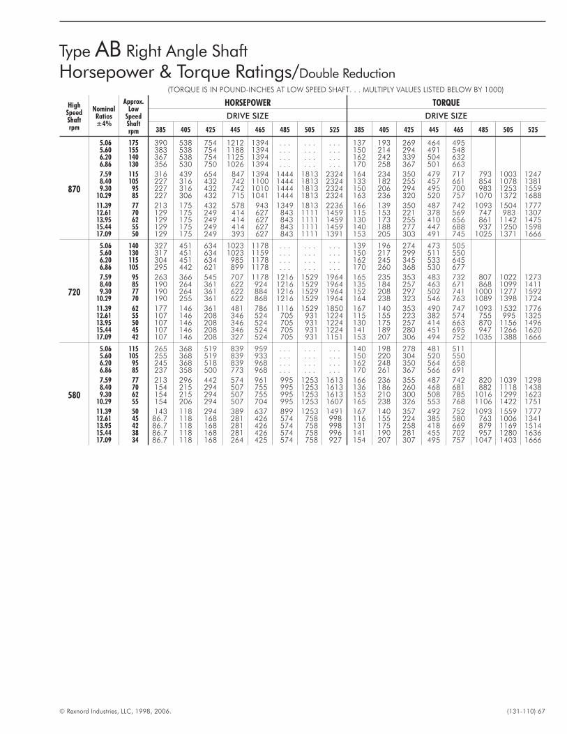
© Rexnord Industries, LLC, 1998, 2006. (131-110) 67
(TORQUE IS IN POUND-INCHES AT LOW SPEED SHAFT. . . MULTIPLY VALUES LISTED BELOW BY 1000)
HighSpeedShaftrpm
NominalRatios±4%
Approx.Low
SpeedShaftrpm
HORSEPOWER TORQUE
DRIVE SIZE DRIVE SIZE
385 405 425 445 465 485 505 525 385 405 425 445 465 485 505 525
870
5.06 175 390 538 754 1212 1394 . . . . . . . . . 137 193 269 464 4955.60 155 383 538 754 1188 1394 . . . . . . . . . 150 214 294 491 5486.20 140 367 538 754 1125 1394 . . . . . . . . . 162 242 339 504 6326.86 130 356 530 750 1026 1394 . . . . . . . . . 170 258 367 501 663
7.59 115 316 439 654 847 1394 1444 1813 2324 164 234 350 479 717 793 1003 12478.40 105 227 316 432 742 1100 1444 1813 2324 133 182 255 457 661 854 1078 13819.30 95 227 316 432 742 1010 1444 1813 2324 150 206 294 495 700 983 1253 1559
10.29 85 227 306 432 715 1041 1444 1813 2324 163 236 320 520 757 1070 1372 1688
11.39 77 213 175 432 578 943 1349 1813 2236 166 139 350 487 742 1093 1504 177712.61 70 129 175 249 414 627 843 1111 1459 115 153 221 378 569 747 983 130713.95 62 129 175 249 414 627 843 1111 1459 130 173 255 410 656 861 1142 147515.44 55 129 175 249 414 627 843 1111 1459 140 188 277 447 688 937 1250 159817.09 50 129 175 249 393 627 843 1111 1391 153 205 303 491 745 1025 1371 1666
720
5.06 140 327 451 634 1023 1178 . . . . . . . . . 139 196 274 473 5055.60 130 317 451 634 1023 1159 . . . . . . . . . 150 217 299 511 5506.20 115 304 451 634 985 1178 . . . . . . . . . 162 245 345 533 6456.86 105 295 442 621 899 1178 . . . . . . . . . 170 260 368 530 677
7.59 95 263 366 545 707 1178 1216 1529 1964 165 235 353 483 732 807 1022 12738.40 85 190 264 361 622 924 1216 1529 1964 135 184 257 463 671 868 1099 14119.30 77 190 264 361 622 884 1216 1529 1964 152 208 297 502 741 1000 1277 1592
10.29 70 190 255 361 622 868 1216 1529 1964 164 238 323 546 763 1089 1398 1724
11.39 62 177 146 361 481 786 1116 1529 1850 167 140 353 490 747 1093 1532 177612.61 55 107 146 208 346 524 705 931 1224 115 155 223 382 574 755 995 132513.95 50 107 146 208 346 524 705 931 1224 130 175 257 414 663 870 1156 149615.44 45 107 146 208 346 524 705 931 1224 141 189 280 451 695 947 1266 162017.09 42 107 146 208 327 524 705 931 1151 153 207 306 494 752 1035 1388 1666
580
5.06 115 265 368 519 839 959 . . . . . . . . . 140 198 278 481 5115.60 105 255 368 519 839 933 . . . . . . . . . 150 220 304 520 5506.20 95 245 368 518 839 968 . . . . . . . . . 162 248 350 564 6586.86 85 237 358 500 773 968 . . . . . . . . . 170 261 367 566 691
7.59 77 213 296 442 574 961 995 1253 1613 166 236 355 487 742 820 1039 12988.40 70 154 215 294 507 755 995 1253 1613 136 186 260 468 681 882 1118 14389.30 62 154 215 294 507 755 995 1253 1613 153 210 300 508 785 1016 1299 1623
10.29 55 154 206 294 507 704 995 1253 1607 165 238 326 553 768 1106 1422 1751
11.39 50 143 118 294 389 637 899 1253 1491 167 140 357 492 752 1093 1559 177712.61 45 86.7 118 168 281 426 574 758 998 116 155 224 385 580 763 1006 134113.95 42 86.7 118 168 281 426 574 758 998 131 175 258 418 669 879 1169 151415.44 38 86.7 118 168 281 426 574 758 996 141 190 281 455 702 957 1280 163617.09 34 86.7 118 168 264 425 574 758 927 154 207 307 495 757 1047 1403 1666
Type AB Right Angle Shaft
Horsepower & Torque Ratings/Double Reduction
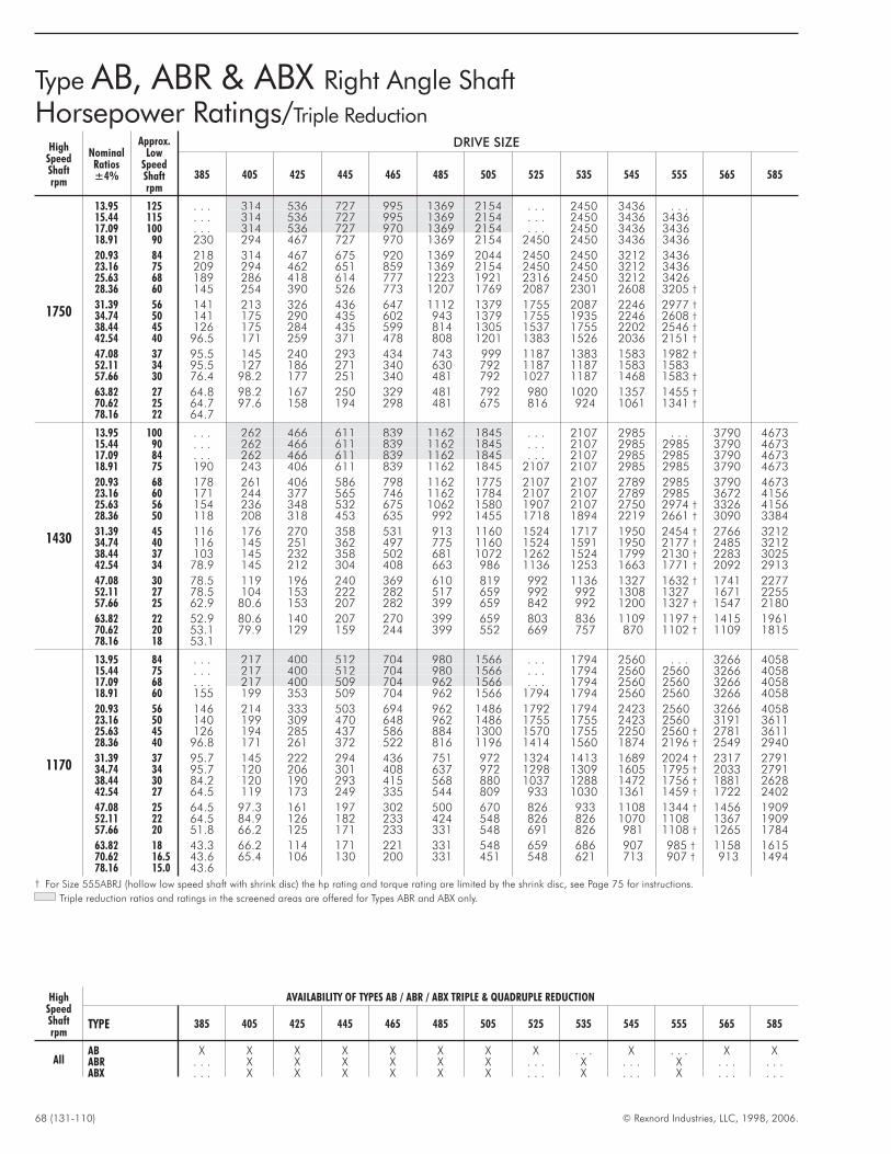
68 (131-110) © Rexnord Industries, LLC, 1998, 2006.
HighSpeedShaftrpm
NominalRatios±4%
Approx.Low
SpeedShaftrpm
DRIVE SIZE
385 405 425 445 465 485 505 525 535 545 555 565 585
1750
13.95 125 . . . 314 536 727 995 1369 2154 . . . 2450 3436 . . .15.44 115 . . . 314 536 727 995 1369 2154 . . . 2450 3436 343617.09 100 . . . 314 536 727 970 1369 2154 . . . 2450 3436 343618.91 90 230 294 467 727 970 1369 2154 2450 2450 3436 3436
20.93 84 218 314 467 675 920 1369 2044 2450 2450 3212 343623.16 75 209 294 462 651 859 1369 2154 2450 2450 3212 343625.63 68 189 286 418 614 777 1223 1921 2316 2450 3212 342628.36 60 145 254 390 526 773 1207 1769 2087 2301 2608 3205 †
31.39 56 141 213 326 436 647 1112 1379 1755 2087 2246 2977 †
34.74 50 141 175 290 435 602 943 1379 1755 1935 2246 2608 †
38.44 45 126 175 284 435 599 814 1305 1537 1755 2202 2546 †
42.54 40 96.5 171 259 371 478 808 1201 1383 1526 2036 2151 †
47.08 37 95.5 145 240 293 434 743 999 1187 1383 1583 1982 †
52.11 34 95.5 127 186 271 340 630 792 1187 1187 1583 1583 †
57.66 30 76.4 98.2 177 251 340 481 792 1027 1187 1468 1583 †
63.82 27 64.8 98.2 167 250 329 481 792 980 1020 1357 1455 †
70.62 25 64.7 97.6 158 194 298 481 675 816 924 1061 1341 †
78.16 22 64.7
1430
13.95 100 . . . 262 466 611 839 1162 1845 . . . 2107 2985 . . . 3790 467315.44 90 . . . 262 466 611 839 1162 1845 . . . 2107 2985 2985 3790 467317.09 84 . . . 262 466 611 839 1162 1845 . . . 2107 2985 2985 3790 467318.91 75 190 243 406 611 839 1162 1845 2107 2107 2985 2985 3790 4673
20.93 68 178 261 406 586 798 1162 1775 2107 2107 2789 2985 3790 467323.16 60 171 244 377 565 746 1162 1784 2107 2107 2789 2985 3672 415625.63 56 154 236 348 532 675 1062 1580 1907 2107 2750 2974 † 3326 415628.36 50 118 208 318 453 635 992 1455 1718 1894 2219 2661 † 3090 3384
31.39 45 116 176 270 358 531 913 1160 1524 1717 1950 2454 † 2766 321234.74 40 116 145 251 362 497 775 1160 1524 1591 1950 2177 † 2485 321238.44 37 103 145 232 358 502 681 1072 1262 1524 1799 2130 † 2283 302542.54 34 78.9 145 212 304 408 663 986 1136 1253 1663 1771 † 2092 2913
47.08 30 78.5 119 196 240 369 610 819 992 1136 1327 1632 † 1741 227752.11 27 78.5 104 153 222 282 517 659 992 992 1308 1327 † 1671 225557.66 25 62.9 80.6 153 207 282 399 659 842 992 1200 1327 † 1547 2180
63.82 22 52.9 80.6 140 207 270 399 659 803 836 1109 1197 † 1415 196170.62 20 53.1 79.9 129 159 244 399 552 669 757 870 1102 † 1109 181578.16 18 53.1
1170
13.95 84 . . . 217 400 512 704 980 1566 . . . 1794 2560 . . . 3266 405815.44 75 . . . 217 400 512 704 980 1566 . . . 1794 2560 2560 3266 405817.09 68 . . . 217 400 509 704 962 1566 . . . 1794 2560 2560 3266 405818.91 60 155 199 353 509 704 962 1566 1794 1794 2560 2560 3266 4058
20.93 56 146 214 333 503 694 962 1486 1792 1794 2423 2560 3266 405823.16 50 140 199 309 470 648 962 1486 1755 1755 2423 2560 3191 361125.63 45 126 194 285 437 586 884 1300 1570 1755 2250 2560 † 2781 361128.36 40 96.8 171 261 372 522 816 1196 1414 1560 1874 2196 † 2549 2940
31.39 37 95.7 145 222 294 436 751 972 1324 1413 1689 2024 † 2317 279134.74 34 95.7 120 206 301 408 637 972 1298 1309 1605 1795 † 2033 279138.44 30 84.2 120 190 293 415 568 880 1037 1288 1472 1756 † 1881 262842.54 27 64.5 119 173 249 335 544 809 933 1030 1361 1459 † 1722 2402
47.08 25 64.5 97.3 161 197 302 500 670 826 933 1108 1344 † 1456 190952.11 22 64.5 84.9 126 182 233 424 548 826 826 1070 1108 † 1367 190957.66 20 51.8 66.2 125 171 233 331 548 691 826 981 1108 † 1265 1784
63.82 18 43.3 66.2 114 171 221 331 548 659 686 907 985 † 1158 161570.62 16.5 43.6 65.4 106 130 200 331 451 548 621 713 907 † 913 149478.16 15.0 43.6
† For Size 555ABRJ (hollow low speed shaft with shrink disc) the hp rating and torque rating are limited by the shrink disc, see Page 75 for instructions.
Triple reduction ratios and ratings in the screened areas are offered for Types ABR and ABX only.
Type AB, ABR & ABX Right Angle Shaft
Horsepower Ratings/Triple Reduction
HighSpeedShaftrpm
AVAILABILITY OF TYPES AB / ABR / ABX TRIPLE & QUADRUPLE REDUCTION
TYPE 385 405 425 445 465 485 505 525 535 545 555 565 585
AllAB X X X X X X X X . . . X . . . X XABR . . . X X X X X X . . . X . . . X . . . . . .ABX . . . X X X X X X . . . X . . . X . . . . . .
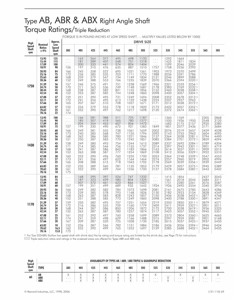
© Rexnord Industries, LLC, 1998, 2006. (131-110) 69
(TORQUE IS IN POUND-INCHES AT LOW SPEED SHAFT. . . MULTIPLY VALUES LISTED BELOW BY 1000)
HighSpeedShaftrpm
NominalRatios±4%
Approx.Low
SpeedShaftrpm
DRIVE SIZE
385 405 425 445 465 485 505 525 535 545 555 565 585
1750
13.95 125 . . . 163 264 377 495 698 1133 . . . 1292 1664 . . .15.44 115 . . . 181 289 407 548 751 1218 . . . 1425 1811 183417.09 100 . . . 200 333 441 574 824 1404 . . . 1599 2046 202918.91 90 156 197 310 476 635 887 1510 1757 1758 2236 2292
20.93 84 166 245 358 522 695 1021 1561 1903 1973 2370 249923.16 75 172 236 385 535 703 1111 1770 1988 2036 2591 278625.63 68 168 259 379 547 734 1149 1834 2121 2246 2899 308828.36 60 152 249 388 553 766 1235 1839 2070 2366 2594 3220 †
31.39 56 157 246 375 491 751 1238 1569 1966 2321 2533 3256 †
34.74 50 170 211 363 536 749 1148 1687 2178 2383 2769 3232 †
38.44 45 168 238 387 582 821 1155 1856 2152 2460 3038 3508 †
42.54 40 152 253 387 585 744 1248 1860 2098 2400 3057 3304 †
47.08 37 159 251 390 495 731 1249 1694 2008 2352 2678 3313 †
52.11 34 172 241 354 495 613 1159 1438 2224 2207 2927 2943 †
57.66 30 165 207 367 510 708 1027 1671 2171 2512 3038 3272 †
63.82 27 152 234 379 553 778 1118 1820 2173 2422 3057 3352 †
70.62 25 161 252 390 497 762 1217 1698 2120 2372 2674 3362 †
78.16 22 174
1430
13.95 100 . . . 166 281 388 511 725 1187 . . . 1360 1769 . . . 2305 286815.44 90 . . . 185 307 419 565 780 1277 . . . 1500 1926 1950 2548 312017.09 84 . . . 204 354 453 607 856 1472 . . . 1682 2175 2157 2920 338018.91 75 157 199 330 490 672 921 1583 1849 1851 2377 2436 3171 3684
20.93 68 166 249 381 555 738 1061 1659 2002 2076 2519 2657 3459 403823.16 60 173 240 385 568 747 1155 1794 2092 2143 2753 2962 3604 409525.63 56 168 262 386 580 780 1221 1846 2137 2364 3038 3281 † 3794 449028.36 50 151 250 387 583 770 1242 1851 2085 2384 2701 3272 † 3859 4094
31.39 45 158 249 380 493 754 1244 1615 2089 2337 2692 3284 † 3789 430434.74 40 171 214 385 546 756 1155 1737 2314 2397 2942 3301 † 3901 471938.44 37 168 241 387 586 842 1183 1866 2163 2614 3037 3591 † 3909 501542.54 34 152 263 388 587 777 1254 1869 2108 2412 3056 3329 † 3922 5310
47.08 30 160 252 390 496 760 1255 1700 2053 2364 2748 3339 † 3547 455352.11 27 173 241 356 497 622 1164 1464 2274 2257 2960 3019 † 3902 499457.66 25 166 208 388 515 718 1043 1702 2178 2569 3039 3356 † 3939 5449
63.82 22 152 235 389 560 781 1135 1853 2179 2429 3057 3375 † 3945 538970.62 20 161 252 390 499 764 1236 1700 2127 2378 2684 3382 † 3443 540278.16 18 175
1170
13.95 84 . . . 168 295 397 524 747 1232 . . . 1415 1854 . . . 2427 304315.44 75 . . . 187 323 429 580 804 1325 . . . 1561 2018 2044 2684 331117.09 68 . . . 207 372 461 623 866 1527 . . . 1751 2280 2261 3076 358718.91 60 157 199 351 499 689 932 1642 1924 1926 2492 2554 3340 3910
20.93 56 166 249 382 582 784 1073 1698 2081 2161 2675 2785 3643 428623.16 50 173 239 385 578 793 1168 1826 2130 2182 2923 3104 3828 434925.63 45 168 263 387 583 828 1243 1857 2150 2406 3038 3452 † 3877 476828.36 40 152 251 388 585 773 1249 1860 2098 2400 2788 3300 † 3891 4347
31.39 37 159 250 382 495 757 1251 1654 2219 2350 2850 3311 † 3879 457134.74 34 172 216 386 555 759 1160 1779 2409 2411 2959 3327 † 3901 501138.44 30 168 244 387 586 850 1206 1872 2172 2700 3038 3619 † 3936 532542.54 27 152 263 387 587 780 1257 1874 2117 2423 3057 3352 † 3945 5351
47.08 25 161 252 392 497 760 1258 1699 2089 2373 2804 3360 † 3625 466552.11 22 174 241 359 498 629 1166 1488 2315 2297 2959 3081 † 3901 516857.66 20 167 209 387 520 725 1058 1730 2185 2615 3037 3425 † 3937 5450
63.82 18 152 236 387 566 782 1151 1884 2186 2436 3056 3394 † 3946 542470.62 16.5 162 252 392 499 765 1253 1697 2129 2385 2688 3402 † 3464 543578.16 15.0 175
† For Size 555ABRJ (hollow low speed shaft with shrink disc) the hp rating and torque rating are limited by the shrink disc, see Page 75 for instructions.
Triple reduction ratios and ratings in the screened areas are offered for Types ABR and ABX only.
Type AB, ABR & ABX Right Angle Shaft
Torque Ratings/Triple Reduction
HighSpeedShaftrpm
AVAILABILITY OF TYPES AB / ABR / ABX TRIPLE & QUADRUPLE REDUCTION
TYPE 385 405 425 445 465 485 505 525 535 545 555 565 585
AllAB X X X X X X X X . . . X . . . X XABR . . . X X X X X X . . . X . . . X . . . . . .ABX . . . X X X X X X . . . X . . . X . . . . . .
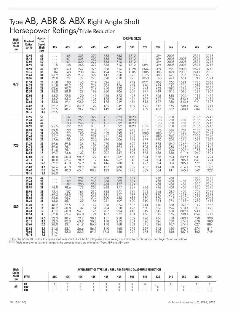
70 (131-110) © Rexnord Industries, LLC, 1998, 2006.
HighSpeedShaftrpm
NominalRatios±4%
Approx.Low
SpeedShaftrpm
DRIVE SIZE
385 405 425 445 465 485 505 525 535 545 555 565 585
870
13.95 62 . . . 165 305 390 538 753 1212 . . . 1394 2005 . . . 2571 321815.44 55 . . . 161 305 390 538 753 1212 . . . 1394 2005 2005 2571 321817.09 50 . . . 161 300 379 538 716 1212 . . . 1394 2005 2005 2571 321818.91 45 115 148 268 379 538 716 1212 1394 1394 2005 2005 2571 3218
20.93 42 109 160 247 376 538 716 1128 1344 1394 1920 2005 2571 321823.16 38 104 148 230 349 494 716 1105 1305 1305 1824 2005 † 2417 293525.63 34 93.9 145 212 327 447 658 973 1176 1305 1673 1986 † 2092 293528.36 31 72.0 127 194 278 390 610 895 1058 1168 1444 1651 † 1917 2324
31.39 28 71.8 108 165 219 326 561 742 1071 1058 1256 1521 † 1723 226834.74 25 71.8 90.2 153 227 304 476 742 970 979 1193 1348 † 1512 223538.44 22 62.6 90.2 141 219 310 432 657 774 963 1095 1318 † 1399 200042.54 21 48.0 88.9 129 186 250 406 604 697 769 1012 1095 † 1281 1804
47.08 18 48.2 72.5 120 147 226 373 498 627 696 838 1009 † 1111 145952.11 17 48.2 63.3 94.9 136 175 316 414 627 627 796 843 † 1017 145957.66 15 38.8 49.4 92.9 129 175 249 414 515 627 730 843 † 941 1327
63.82 14 32.2 49.4 84.9 129 165 249 409 491 512 675 738 † 861 121170.62 12.5 32.5 48.7 78.7 96.9 149 249 336 409 463 532 680 † 684 112078.16 11.0 32.5
720
13.95 50 . . . 137 255 327 451 623 1023 . . . 1178 1701 . . . 2186 274615.44 45 . . . 133 255 327 451 623 1023 . . . 1178 1701 1701 2186 274617.09 42 . . . 133 248 313 451 592 1023 . . . 1178 1701 1701 2186 274618.91 38 95.5 122 221 313 451 592 1023 1174 1175 1701 1701 2186 2746
20.93 34 89.9 133 205 312 451 592 943 1117 1175 1589 1701 2140 274623.16 31 86.0 123 190 289 412 592 915 1080 1080 1510 1692 † 2000 257125.63 28 77.7 120 175 271 371 544 808 977 1080 1385 1655 † 1738 254028.36 25 59.6 105 160 230 324 506 743 879 970 1209 1375 † 1591 1964
31.39 22 59.6 89.8 136 182 270 465 622 887 878 1040 1267 † 1426 194534.74 21 59.6 75.1 126 190 252 394 614 805 812 988 1123 † 1251 184938.44 18 51.8 75.1 117 181 257 361 545 642 799 906 1097 † 1158 165542.54 17 39.7 73.6 107 154 207 337 501 578 638 838 911 † 1060 1501
47.08 15 40.0 60.0 98.9 122 187 309 412 524 578 693 839 † 931 122452.11 14 40.0 52.4 78.9 112 146 262 346 524 524 658 705 † 841 122457.66 12.5 32.2 41.0 76.9 107 146 208 346 427 524 604 705 † 779 1098
63.82 11.0 26.6 41.0 70.2 107 137 208 339 407 424 558 614 † 713 100670.62 10.0 26.9 40.3 65.1 80.2 123 206 278 339 384 441 565 † 569 92978.16 9.1 26.9
580
13.95 42 . . . 112 207 266 368 502 839 . . . 968 1401 . . . 1805 227515.44 38 . . . 107 207 266 368 502 839 . . . 968 1401 1401 1805 227517.09 34 . . . 107 200 252 368 477 839 . . . 968 1401 1401 1805 227518.91 31 76.9 98.6 178 252 368 477 839 946 946 1401 1401 1805 2275
20.93 28 72.4 107 165 252 368 477 764 904 946 1280 1401 1724 227523.16 25 69.3 98.9 153 233 334 477 737 870 870 1216 1373 † 1611 215325.63 22 62.6 96.7 141 219 300 438 653 789 870 1115 1342 † 1400 204628.36 21 48.0 85.1 129 186 261 409 600 710 784 974 1115 † 1282 1613
31.39 18 48.2 72.5 110 147 218 376 507 714 710 838 1027 † 1149 156734.74 17 48.2 60.8 102 154 204 318 495 650 656 796 910 † 1008 149038.44 15 41.7 60.8 94.1 146 207 294 440 519 645 730 889 † 933 133342.54 14 32.0 59.4 86.0 124 167 272 404 466 515 675 738 † 854 1217
47.08 12.5 32.3 48.4 79.7 98.1 151 250 332 426 466 558 680 † 758 99852.11 11.0 32.3 42.3 63.9 90.6 118 212 281 426 426 530 574 † 678 98857.66 10.0 26.0 33.1 61.9 86.7 118 168 281 345 426 487 574 † 627 884
63.82 9.1 21.5 33.1 56.6 86.7 110 168 273 329 342 450 497 † 574 81170.62 8.3 21.7 32.5 52.5 64.7 99.5 166 224 273 310 356 457 † 460 74978.16 7.5 21.7
† For Size 555ABRJ (hollow low speed shaft with shrink disc) the hp rating and torque rating are limited by the shrink disc, see Page 75 for instructions.
Triple reduction ratios and ratings in the screened areas are offered for Types ABR and ABX only.
Type AB, ABR & ABX Right Angle Shaft
Horsepower Ratings/Triple Reduction
HighSpeedShaftrpm
AVAILABILITY OF TYPES AB / ABR / ABX TRIPLE & QUADRUPLE REDUCTION
TYPE 385 405 425 445 465 485 505 525 535 545 555 565 585
AllAB X X X X X X X X . . . X . . . X XABR . . . X X X X X X . . . X . . . X . . . . . .ABX . . . X X X X X X . . . X . . . X . . . . . .

© Rexnord Industries, LLC, 1998, 2006. (131-110) 71
(TORQUE IS IN POUND-INCHES AT LOW SPEED SHAFT. . . MULTIPLY VALUES LISTED BELOW BY 1000)
HighSpeedShaftrpm
NominalRatios±4%
Approx.Low
SpeedShaftrpm
DRIVE SIZE
385 405 425 445 465 485 505 525 535 545 555 565 585
870
13.95 62 . . . 172 303 407 538 772 1282 . . . 1479 1953 . . . 2570 324615.44 55 . . . 186 331 440 596 831 1379 . . . 1631 2126 2153 2842 353117.09 50 . . . 207 375 462 640 867 1589 . . . 1830 2402 2381 3256 382618.91 45 157 199 358 499 709 933 1709 2010 2013 2625 2690 3536 4170
20.93 42 167 251 381 585 818 1074 1733 2099 2258 2850 2933 3856 457123.16 38 172 239 386 577 813 1169 1826 2130 2182 2959 3270 † 3899 475425.63 34 168 264 387 586 849 1244 1869 2166 2406 3038 3601 † 3922 521128.36 31 152 251 388 588 777 1255 1872 2111 2416 2889 3337 † 3935 4621
31.39 28 161 251 382 496 761 1256 1698 2413 2367 2850 3346 † 3879 499634.74 25 174 219 386 563 760 1166 1826 2421 2425 2958 3360 † 3902 539738.44 22 168 247 387 589 854 1233 1879 2180 2715 3039 3653 † 3937 545042.54 21 152 265 388 590 783 1262 1882 2126 2433 3057 3383 † 3947 5405
47.08 18 162 253 392 499 765 1262 1699 2133 2381 2852 3393 † 3720 479552.11 17 175 241 363 500 635 1169 1512 2363 2344 2961 3152 † 3903 531157.66 15 168 210 387 527 733 1070 1757 2190 2669 3039 3504 † 3939 5452
63.82 14 152 237 387 574 785 1164 1891 2190 2445 3058 3420 † 3946 547070.62 12.5 162 253 391 500 766 1267 1701 2137 2391 2697 3430 † 3490 547978.16 11.0 176
720
13.95 50 . . . 172 306 412 545 772 1308 . . . 1510 2002 . . . 2640 334715.44 45 . . . 186 334 445 604 831 1406 . . . 1665 2179 2207 2919 364117.09 42 . . . 206 375 461 648 866 1621 . . . 1868 2462 2441 3345 394518.91 38 157 199 357 498 718 932 1743 2046 2050 2691 2757 3633 4300
20.93 34 166 252 382 586 828 1073 1751 2108 2300 2850 3007 3879 471323.16 31 172 240 385 577 820 1168 1827 2130 2182 2960 3334 † 3899 503225.63 28 168 264 386 587 852 1243 1875 2175 2406 3039 3626 † 3938 545028.36 25 152 251 387 588 780 1258 1878 2119 2425 2923 3358 † 3946 4719
31.39 22 161 252 380 498 762 1258 1720 2415 2373 2851 3368 † 3879 517734.74 21 174 220 384 569 762 1166 1826 2428 2430 2960 3382 † 3901 539538.44 18 168 248 388 588 856 1246 1884 2185 2722 3038 3674 † 3938 544942.54 17 152 265 388 590 783 1266 1886 2131 2439 3059 3401 † 3947 5434
47.08 15 162 253 391 501 765 1263 1698 2154 2389 2850 3409 † 3767 486152.11 14 176 241 365 498 640 1171 1527 2386 2368 2957 3185 † 3900 538457.66 12.5 169 210 387 528 739 1080 1775 2194 2695 3038 3541 † 3940 5451
63.82 11.0 151 237 387 575 787 1175 1894 2193 2447 3055 3438 † 3948 549170.62 10.0 162 253 391 500 765 1267 1700 2140 2396 2702 3443 † 3508 549278.16 9.1 176
580
13.95 42 . . . 175 308 416 552 772 1331 . . . 1540 2047 . . . 2706 344215.44 38 . . . 186 337 450 611 831 1432 . . . 1699 2228 2256 2992 374517.09 34 . . . 206 375 461 657 866 1650 . . . 1906 2517 2496 3429 405718.91 31 157 199 357 498 727 932 1775 2047 2049 2751 2819 3724 4422
20.93 28 166 252 381 588 839 1074 1761 2118 2298 2850 3075 3879 484723.16 25 172 240 385 578 825 1168 1827 2130 2182 2959 3359 † 3898 523125.63 22 168 265 386 589 855 1242 1881 2180 2406 3037 3650 † 3937 544928.36 21 152 252 387 590 780 1262 1882 2125 2433 2923 3380 † 3948 4811
31.39 18 162 253 382 499 763 1263 1740 2413 2382 2852 3389 † 3880 517734.74 17 175 221 386 573 765 1168 1828 2434 2437 2961 3402 † 3902 539738.44 15 168 250 387 589 856 1259 1888 2193 2728 3039 3696 † 3939 544842.54 14 152 265 388 590 784 1268 1888 2132 2444 3058 3420 † 3947 5469
47.08 12.5 163 253 391 500 767 1269 1699 2174 2391 2849 3430 † 3807 492052.11 11.0 176 242 367 500 642 1177 1540 2408 2389 2957 3219 † 3903 539557.66 10.0 169 211 387 531 741 1083 1789 2201 2720 3041 3579 † 3936 5447
63.82 9.1 152 238 387 579 785 1179 1893 2201 2450 3058 3455 † 3946 549570.62 8.3 163 253 391 501 768 1267 1701 2140 2401 2708 3457 † 3521 549678.16 7.5 176
† For Size 555ABRJ (hollow low speed shaft with shrink disc) the hp rating and torque rating are limited by the shrink disc, see Page 75 for instructions.
Triple reduction ratios and ratings in the screened areas are offered for Types ABR and ABX only.
Type AB, ABR & ABX Right Angle Shaft
Torque Ratings/Triple Reduction
HighSpeedShaftrpm
AVAILABILITY OF TYPES AB / ABR / ABX TRIPLE & QUADRUPLE REDUCTION
TYPE 385 405 425 445 465 485 505 525 535 545 555 565 585
AllAB X X X X X X X X . . . X . . . X XABR . . . X X X X X X . . . X . . . X . . . . . .ABX . . . X X X X X X . . . X . . . X . . . . . .
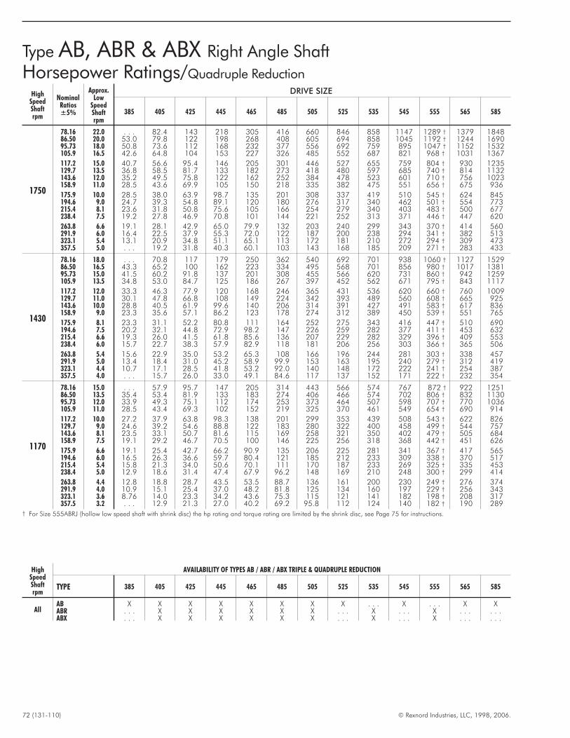
72 (131-110) © Rexnord Industries, LLC, 1998, 2006.
HighSpeedShaftrpm
NominalRatios±5%
Approx.Low
SpeedShaftrpm
DRIVE SIZE
385 405 425 445 465 485 505 525 535 545 555 565 585
1750
78.16 22.0 . . . 82.4 143 218 305 416 660 846 858 1147 1289 † 1379 184886.50 20.0 53.0 79.8 122 198 268 408 605 694 858 1045 1192 † 1244 169095.73 18.0 50.8 73.6 112 168 232 377 556 692 759 895 1047 † 1152 1532105.9 16.5 42.6 64.8 104 153 227 326 485 552 687 821 968 † 1031 1367
117.2 15.0 40.7 56.6 95.4 146 205 301 446 527 655 759 804 † 930 1235129.7 13.5 36.8 58.5 81.7 133 182 273 418 480 597 685 740 † 814 1132143.6 12.0 35.2 49.5 75.8 122 162 252 384 478 523 601 710 † 756 1023158.9 11.0 28.5 43.6 69.9 105 150 218 335 382 475 551 656 † 675 936
175.9 10.0 28.5 38.0 63.9 98.7 135 201 308 337 419 510 545 † 624 845194.6 9.0 24.7 39.3 54.8 89.1 120 180 276 317 340 462 501 † 554 773215.4 8.1 23.6 31.8 50.8 75.6 105 166 254 279 340 403 483 † 500 677238.4 7.5 19.2 27.8 46.9 70.8 101 144 221 252 313 371 446 † 447 620
263.8 6.6 19.1 28.1 42.9 65.0 79.9 132 203 240 299 343 370 † 414 560291.9 6.0 16.4 22.5 37.9 55.3 72.0 122 187 200 238 294 341 † 382 513323.1 5.4 13.1 20.9 34.8 51.1 65.1 113 172 181 210 272 294 † 309 473357.5 5.0 . . . 19.2 31.8 40.3 60.1 103 143 168 185 209 271 † 283 433
1430
78.16 18.0 . . . 70.8 117 179 250 362 540 692 701 938 1060 † 1127 152986.50 16.5 43.3 65.2 100 162 223 334 495 568 701 856 980 † 1017 138195.73 15.0 41.5 60.2 91.8 137 201 308 455 566 620 731 860 † 942 1259105.9 13.5 34.8 53.0 84.7 125 186 267 397 452 562 671 795 † 843 1117
117.2 12.0 33.3 46.3 77.9 120 168 246 365 431 536 620 660 † 760 1009129.7 11.0 30.1 47.8 66.8 108 149 224 342 393 489 560 608 † 665 925143.6 10.0 28.8 40.5 61.9 99.6 140 206 314 391 427 491 583 † 617 836158.9 9.0 23.3 35.6 57.1 86.2 123 178 274 312 389 450 539 † 551 765
175.9 8.1 23.3 31.1 52.2 80.8 111 164 252 275 343 416 447 † 510 690194.6 7.5 20.2 32.1 44.8 72.9 98.2 147 226 259 282 377 411 † 453 632215.4 6.6 19.3 26.0 41.5 61.8 85.6 136 207 229 282 329 396 † 409 553238.4 6.0 15.7 22.7 38.3 57.9 82.9 118 181 206 256 303 366 † 365 506
263.8 5.4 15.6 22.9 35.0 53.2 65.3 108 166 196 244 281 303 † 338 457291.9 5.0 13.4 18.4 31.0 45.2 58.9 99.9 153 163 195 240 279 † 312 419323.1 4.4 10.7 17.1 28.5 41.8 53.2 92.0 140 148 172 222 241 † 254 387357.5 4.0 . . . 15.7 26.0 33.0 49.1 84.6 117 137 152 171 222 † 232 354
1170
78.16 15.0 . . . 57.9 95.7 147 205 314 443 566 574 767 872 † 922 125186.50 13.5 35.4 53.4 81.9 133 183 274 406 466 574 702 806 † 832 113095.73 12.0 33.9 49.3 75.1 112 174 253 373 464 507 598 707 † 770 1036105.9 11.0 28.5 43.4 69.3 102 152 219 325 370 461 549 654 † 690 914
117.2 10.0 27.2 37.9 63.8 98.3 138 201 299 353 439 508 543 † 622 826129.7 9.0 24.6 39.2 54.6 88.8 122 183 280 322 400 458 499 † 544 757143.6 8.1 23.5 33.1 50.7 81.6 115 169 258 321 350 402 479 † 505 684158.9 7.5 19.1 29.2 46.7 70.5 100 146 225 256 318 368 442 † 451 626
175.9 6.6 19.1 25.4 42.7 66.2 90.9 135 206 225 281 341 367 † 417 565194.6 6.0 16.5 26.3 36.6 59.7 80.4 121 185 212 233 309 338 † 370 517215.4 5.4 15.8 21.3 34.0 50.6 70.1 111 170 187 233 269 325 † 335 453238.4 5.0 12.9 18.6 31.4 47.4 67.9 96.2 148 169 210 248 300 † 299 414
263.8 4.4 12.8 18.8 28.7 43.5 53.5 88.7 136 161 200 230 249 † 276 374291.9 4.0 10.9 15.1 25.4 37.0 48.2 81.8 125 134 160 197 229 † 256 343323.1 3.6 8.76 14.0 23.3 34.2 43.6 75.3 115 121 141 182 198 † 208 317357.5 3.2 . . . 12.9 21.3 27.0 40.2 69.2 95.8 112 124 140 182 † 190 289
† For Size 555ABRJ (hollow low speed shaft with shrink disc) the hp rating and torque rating are limited by the shrink disc, see Page 75 for instructions.
Type AB, ABR & ABX Right Angle Shaft
Horsepower Ratings/Quadruple Reduction
HighSpeedShaftrpm
AVAILABILITY OF TYPES AB / ABR / ABX TRIPLE & QUADRUPLE REDUCTION
TYPE 385 405 425 445 465 485 505 525 535 545 555 565 585
AllAB X X X X X X X X . . . X . . . X XABR . . . X X X X X X . . . X . . . X . . . . . .ABX . . . X X X X X X . . . X . . . X . . . . . .
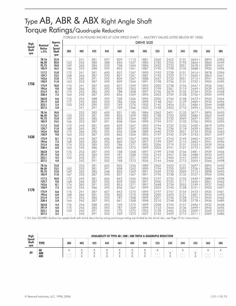
© Rexnord Industries, LLC, 1998, 2006. (131-110) 73
(TORQUE IS IN POUND-INCHES AT LOW SPEED SHAFT. . . MULTIPLY VALUES LISTED BELOW BY 1000)
HighSpeedShaftrpm
NominalRatios±5%
Approx.Low
SpeedShaftrpm
DRIVE SIZE
385 405 425 445 465 485 505 525 535 545 555 565 585
1750
78.16 22.0 . . . 241 381 597 829 1113 1881 2360 2452 3131 3654 † 3894 538386.50 20.0 163 252 380 588 840 1257 1883 2185 2704 3192 3664 † 3860 544995.73 18.0 169 265 384 550 758 1264 1884 2432 2733 3051 3678 † 3899 5431105.9 16.5 166 253 388 592 855 1261 1887 2190 2728 3132 3688 † 3900 5396
117.2 15.0 172 241 381 600 837 1267 1890 2192 2728 3151 3414 † 3878 5396129.7 13.5 168 265 387 593 857 1261 1887 2192 2729 3117 3420 † 3863 5461143.6 12.0 174 265 391 592 804 1267 1888 2437 2732 3051 3715 † 3941 5463158.9 11.0 163 253 387 590 859 1264 1891 2198 2736 3131 3722 † 3905 5495
175.9 10.0 176 241 387 605 837 1269 1893 2200 2738 3154 3447 † 3936 5461194.6 9.0 168 266 381 592 859 1263 1893 2199 2361 3119 3449 † 3939 5493215.4 8.1 174 253 385 592 788 1268 1897 2196 2679 3133 3750 † 3935 5458238.4 7.5 163 242 387 593 856 1269 1895 2203 2739 3128 3756 † 3904 5495
263.8 6.6 176 254 388 592 768 1266 1895 2200 2744 3148 3473 † 3943 5464291.9 6.0 177 242 384 593 786 1266 1899 2148 2451 3129 3484 † 3935 5496323.1 5.4 153 242 390 593 769 1276 1902 2140 2454 3151 3484 † 3544 5488357.5 5.0 . . . 241 391 501 769 1266 1833 2148 2453 2710 3495 † 3554 5495
1430
78.16 18.0 . . . 253 382 600 831 1185 1884 2362 2451 3133 3677 † 3895 545086.50 16.5 163 252 381 589 855 1259 1885 2188 2703 3200 3686 † 3862 544995.73 15.0 169 265 385 549 803 1264 1887 2435 2732 3049 3697 † 3901 5462105.9 13.5 166 253 387 591 858 1264 1890 2194 2731 3132 3706 † 3903 5395
117.2 12.0 172 242 381 604 839 1267 1892 2194 2732 3150 3430 † 3879 5395129.7 11.0 168 265 387 589 859 1267 1890 2196 2736 3118 3439 † 3862 5461143.6 10.0 174 266 390 592 850 1268 1889 2440 2729 3051 3733 † 3936 5463158.9 9.0 163 253 387 592 862 1264 1893 2197 2742 3129 3743 † 3901 5497
175.9 8.1 176 242 387 606 842 1267 1895 2197 2743 3149 3460 † 3937 5457194.6 7.5 168 265 382 593 860 1263 1897 2199 2397 3115 3463 † 3941 5496215.4 6.6 174 253 385 592 786 1271 1892 2206 2719 3131 3763 † 3939 5456238.4 6.0 163 242 386 593 860 1272 1899 2204 2741 3127 3772 † 3901 5489
263.8 5.4 176 253 387 593 768 1268 1897 2199 2740 3156 3481 † 3939 5456291.9 5.0 177 242 384 593 787 1268 1902 2143 2457 3126 3488 † 3933 5493323.1 4.4 153 242 391 594 769 1271 1895 2141 2460 3147 3495 † 3566 5495357.5 4.0 . . . 242 391 502 768 1273 1836 2144 2466 2713 3504 † 3566 5498
1170
78.16 15.0 . . . 253 381 602 833 1256 1889 2362 2453 3131 3697 † 3894 545086.50 13.5 163 253 381 591 858 1262 1890 2194 2705 3207 3706 † 3862 544995.73 12.0 169 265 385 548 850 1269 1891 2439 2730 3049 3715 † 3898 5493105.9 11.0 167 253 387 590 857 1267 1891 2195 2738 3132 3727 † 3904 5396
117.2 10.0 172 242 381 604 843 1265 1895 2197 2735 3155 3449 † 3880 5398129.7 9.0 168 266 387 592 859 1265 1891 2200 2735 3117 3450 † 3861 5462143.6 8.1 174 265 391 592 853 1271 1897 2448 2734 3053 3749 † 3937 5463158.9 7.5 163 254 386 592 856 1267 1899 2203 2740 3128 3751 † 3902 5497
175.9 6.6 176 241 387 607 843 1275 1894 2197 2747 3154 3472 † 3935 5461194.6 6.0 168 266 381 593 860 1270 1898 2200 2420 3121 3481 † 3934 5495215.4 5.4 174 254 385 593 787 1268 1899 2201 2746 3128 3775 † 3943 5462238.4 5.0 164 242 387 593 861 1268 1898 2210 2748 3128 3778 † 3906 5489
263.8 4.4 176 254 388 593 769 1272 1899 2208 2745 3157 3496 † 3932 5458291.9 4.0 175 243 385 593 787 1269 1899 2153 2464 3136 3499 † 3945 5496323.1 3.6 153 242 391 594 770 1272 1902 2139 2465 3154 3509 † 3569 5502357.5 3.2 . . . 243 391 502 769 1272 1837 2142 2459 2715 3511 † 3569 5486
† For Size 555ABRJ (hollow low speed shaft with shrink disc) the hp rating and torque rating are limited by the shrink disc, see Page 75 for instructions.
Type AB, ABR & ABX Right Angle Shaft
Torque Ratings/Quadruple Reduction
HighSpeedShaftrpm
AVAILABILITY OF TYPES AB / ABR / ABX TRIPLE & QUADRUPLE REDUCTION
TYPE 385 405 425 445 465 485 505 525 535 545 555 565 585
AllAB X X X X X X X X . . . X . . . X XABR . . . X X X X X X . . . X . . . X . . . . . .ABX . . . X X X X X X . . . X . . . X . . . . . .

74 (131-110) © Rexnord Industries, LLC, 1998, 2006.
HighSpeedShaftrpm
NominalRatios±5%
Approx.Low
SpeedShaftrpm
DRIVE SIZE
385 405 425 445 465 485 505 525 535 545 555 565 585
870
78.16 11.0 . . . 43.1 71.1 110 153 236 330 421 427 570 653 † 686 93086.50 10.0 26.3 39.8 60.9 99.0 136 204 302 347 427 523 603 † 619 84095.73 9.1 25.2 36.7 55.8 83.4 130 188 278 346 377 445 529 † 573 770105.9 8.3 21.2 32.3 51.5 76.2 113 163 242 276 343 408 489 † 513 680
117.2 7.5 20.3 28.2 47.4 73.3 103 150 222 263 327 377 406 † 462 614129.7 6.8 18.3 29.1 40.6 66.1 90.8 136 209 240 298 341 374 † 405 563143.6 6.1 17.5 24.6 37.7 60.7 85.5 126 192 239 260 299 358 † 376 508158.9 5.5 14.2 21.7 34.8 52.5 74.7 109 167 190 237 274 331 † 335 465
175.9 5.0 14.2 18.9 31.8 49.3 67.7 100 154 168 209 253 274 † 310 420194.6 4.5 12.3 19.6 27.2 44.4 59.8 89.9 138 158 175 230 252 † 275 384215.4 4.1 11.7 15.8 25.3 37.7 52.1 82.8 126 139 173 200 243 † 249 337238.4 3.8 9.57 13.8 23.3 35.2 50.5 71.6 110 125 156 185 224 † 222 308
263.8 3.3 9.51 14.0 21.3 32.4 39.8 66.0 101 120 149 171 186 † 206 278291.9 3.0 8.14 11.2 18.9 27.5 35.9 60.8 93.0 99.4 119 146 171 † 190 255323.1 2.7 6.51 10.4 17.3 25.4 32.4 56.0 85.4 90.3 105 135 148 † 155 235357.5 2.5 . . . 9.57 15.8 20.1 29.9 51.5 71.4 83.5 92.3 104 136 † 142 215
720
78.16 9.1 . . . 35.6 58.9 90.8 127 196 273 348 353 472 543 † 567 77086.50 8.3 21.8 32.9 50.4 82.0 113 169 250 287 353 433 501 † 512 69595.73 7.5 20.9 30.4 46.2 69.0 107 156 230 286 312 368 440 † 474 638105.9 6.8 17.5 26.7 42.7 63.1 93.9 135 201 228 284 338 406 † 424 562
117.2 6.1 16.8 23.3 39.2 60.7 85.0 124 184 218 271 312 337 † 383 508129.7 5.5 15.1 24.1 33.6 54.7 75.2 113 173 198 247 282 310 † 335 466143.6 5.0 14.5 20.4 31.2 50.3 70.8 104 159 198 215 247 297 † 311 421158.9 4.5 11.8 18.0 28.8 43.5 61.9 90.0 138 158 196 227 275 † 278 385
175.9 4.1 11.7 15.7 26.3 40.8 56.1 82.9 127 139 173 210 228 † 257 348194.6 3.8 10.2 16.2 22.5 36.7 49.5 74.4 114 131 146 190 210 † 228 318215.4 3.3 9.72 13.1 20.9 31.2 43.2 68.5 105 115 144 166 201 † 206 279238.4 3.0 7.92 11.4 19.3 29.2 41.8 59.3 91.2 104 129 153 186 † 184 255
263.8 2.7 7.87 11.6 17.6 26.8 32.9 54.6 83.7 99.0 123 141 154 † 170 230291.9 2.5 6.73 9.27 15.6 22.8 29.7 50.4 77.0 82.3 98.3 121 142 † 157 211323.1 2.2 5.39 8.62 14.3 21.1 26.8 46.4 70.7 74.8 86.7 112 123 † 129 195357.5 2.0 . . . 7.92 13.1 16.6 24.8 42.6 59.1 69.1 76.4 86.2 113 † 118 178
580
78.16 7.5 . . . 28.7 47.4 73.3 103 158 220 281 284 380 439 † 457 62086.5 6.8 17.6 26.5 40.6 66.1 90.9 136 202 232 284 348 406 † 412 560
95.73 6.1 16.8 24.5 37.2 55.6 86.6 126 185 231 251 297 356 † 382 514105.9 5.5 14.1 21.6 34.4 50.8 75.7 109 162 184 229 272 328 † 342 453
117.2 5.0 13.5 18.8 31.6 49.0 68.6 100 148 176 219 252 273 † 308 409129.7 4.5 12.2 19.4 27.1 44.1 60.6 91.0 139 160 199 227 251 † 270 375143.6 4.1 11.7 16.4 25.1 40.5 57.1 83.8 128 159 173 199 240 † 250 339158.9 3.8 9.50 14.5 23.2 35.0 49.9 72.5 112 127 158 183 222 † 224 310
175.9 3.3 9.45 12.6 21.2 32.9 45.2 66.8 102 112 139 169 184 † 207 280194.6 3.0 8.19 13.0 18.2 29.6 39.9 59.9 91.8 105 118 153 169 † 184 256215.4 2.7 7.83 10.6 16.8 25.1 34.8 55.2 84.3 92.9 116 133 163 † 166 224238.4 2.5 6.38 9.21 15.5 23.5 33.7 47.8 73.5 83.7 104 123 150 † 148 205
263.8 2.2 6.34 9.31 14.2 21.6 26.5 44.0 67.5 79.8 99.3 114 125 † 137 185291.9 2.0 5.43 7.47 12.6 18.4 23.9 40.6 62.0 66.3 79.3 97.5 115 † 127 170323.1 1.8 4.34 6.94 11.5 17.0 21.6 37.4 57.0 60.3 69.8 90.2 98.9 † 104 157357.5 1.6 . . . 6.38 10.5 13.4 20.0 34.3 47.7 55.7 61.6 69.4 91.0 † 94.9 143
† For Size 555ABRJ (hollow low speed shaft with shrink disc) the hp rating and torque rating are limited by the shrink disc, see Page 75 for instructions.
Type AB, ABR & ABX Right Angle Shaft
Horsepower Ratings/Quadruple Reduction
HighSpeedShaftrpm
AVAILABILITY OF TYPES AB / ABR / ABX TRIPLE & QUADRUPLE REDUCTION
TYPE 385 405 425 445 465 485 505 525 535 545 555 565 585
AllAB X X X X X X X X . . . X . . . X XABR . . . X X X X X X . . . X . . . X . . . . . .ABX . . . X X X X X X . . . X . . . X . . . . . .
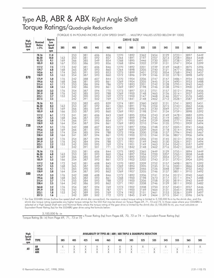
© Rexnord Industries, LLC, 1998, 2006. (131-110) 75
(TORQUE IS IN POUND-INCHES AT LOW SPEED SHAFT. . . MULTIPLY VALUES LISTED BELOW BY 1000)
HighSpeedShaftrpm
NominalRatios±5%
Approx.Low
SpeedShaftrpm
DRIVE SIZE
385 405 425 445 465 485 505 525 535 545 555 565 585
870
78.16 11.0 . . . 253 381 606 836 1270 1892 2362 2454 3129 3723 † 3897 544986.50 10.0 163 253 381 592 857 1264 1891 2197 2707 3213 3728 † 3864 544895.73 9.1 169 266 385 549 854 1268 1895 2446 2730 3051 3738 † 3901 5491105.9 8.3 167 253 386 593 856 1268 1894 2202 2739 3131 3747 † 3904 5399
117.2 7.5 173 242 381 606 846 1270 1892 2201 2739 3149 3468 † 3875 5396129.7 6.8 168 265 387 593 860 1264 1898 2205 2740 3121 3477 † 3866 5463143.6 6.1 174 265 391 593 853 1275 1899 2451 2732 3054 3768 † 3942 5457158.9 5.5 163 254 387 593 860 1272 1896 2199 2746 3132 3778 † 3898 5492
175.9 5.0 176 242 388 607 844 1270 1904 2206 2747 3147 3486 † 3934 5460194.6 4.5 168 266 381 593 861 1269 1904 2205 2445 3124 3490 † 3933 5488215.4 4.1 173 253 386 594 786 1272 1893 2201 2742 3128 3795 † 3942 5465238.4 3.8 164 242 386 593 861 1269 1897 2198 2746 3138 3794 † 3900 5491
263.8 3.3 176 254 387 594 770 1273 1897 2213 2751 3157 3512 † 3946 5456291.9 3.0 176 242 385 593 788 1269 1900 2148 2465 3126 3514 † 3937 5495323.1 2.7 153 242 390 593 769 1272 1900 2147 2468 3146 3527 † 3576 5485357.5 2.5 . . . 242 391 502 769 1273 1841 2148 2462 2712 3528 † 3587 5489
720
78.16 9.1 . . . 253 382 605 839 1274 1891 2360 2452 3131 3741 † 3892 545186.50 8.3 163 253 381 592 861 1265 1891 2196 2704 3215 3743 † 3862 544695.73 7.5 169 266 385 549 849 1271 1895 2443 2730 3049 3757 † 3899 5497105.9 6.8 166 253 387 593 860 1269 1901 2198 2741 3134 3759 † 3898 5392
117.2 6.1 173 241 381 606 843 1269 1895 2204 2743 3149 3478 † 3882 5395129.7 5.5 168 266 387 593 861 1269 1899 2198 2745 3119 3483 † 3864 5464143.6 5.0 174 266 391 593 854 1271 1900 2454 2729 3048 3777 † 3940 5464158.9 4.5 164 254 387 594 861 1269 1893 2210 2744 3135 3793 † 3909 5494
175.9 4.1 176 242 388 607 845 1272 1897 2206 2748 3157 3505 † 3941 5466194.6 3.8 169 266 381 593 861 1269 1900 2209 2464 3118 3514 † 3940 5492215.4 3.3 174 254 385 594 788 1272 1906 2200 2758 3137 3794 † 3940 5467238.4 3.0 164 241 387 594 861 1270 1900 2210 2744 3136 3807 † 3906 5494
263.8 2.7 176 254 387 594 769 1273 1899 2206 2744 3145 3513 † 3935 5454291.9 2.5 176 242 384 594 788 1271 1901 2149 2460 3130 3526 † 3931 5494323.1 2.2 153 242 390 595 769 1274 1901 2149 2463 3154 3542 † 3597 5499357.5 2.0 . . . 242 391 501 771 1273 1842 2148 2462 2716 3542 † 3602 5491
580
78.16 7.5 . . . 253 381 606 844 1275 1892 2365 2449 3129 3755 † 3894 544986.50 6.8 163 253 381 593 860 1264 1897 2204 2700 3207 3765 † 3858 544895.73 6.1 169 266 385 549 853 1275 1892 2450 2727 3054 3773 † 3901 5498105.9 5.5 166 254 387 593 861 1272 1902 2202 2743 3131 3770 † 3904 5395
117.2 5.0 172 242 381 608 845 1270 1892 2209 2752 3157 3498 † 3875 5392129.7 4.5 168 265 387 593 861 1269 1894 2205 2745 3116 3500 † 3866 5458143.6 4.1 175 265 390 593 855 1272 1899 2446 2726 3048 3789 † 3932 5462158.9 3.8 164 254 387 593 862 1269 1907 2205 2746 3137 3801 † 3910 5492
175.9 3.3 176 242 388 608 846 1272 1892 2206 2741 3154 3512 † 3940 5460194.6 3.0 168 265 382 593 861 1268 1900 2198 2473 3117 3511 † 3947 5488215.4 2.7 174 255 384 593 788 1272 1900 2206 2758 3120 3819 † 3942 5449238.4 2.5 164 242 386 593 862 1271 1901 2208 2746 3129 3811 † 3900 5482
263.8 2.2 176 254 387 594 769 1273 1902 2208 2750 3157 3540 † 3937 5446291.9 2.0 176 242 385 595 787 1271 1900 2149 2464 3131 3545 † 3948 5495323.1 1.8 153 242 389 595 769 1274 1902 2151 2461 3153 3536 † 3599 5497357.5 1.6 . . . 242 389 502 772 1272 1845 2149 2464 2715 3541 † 3596 5476
† For Size 555ABRJ drives (hollow low speed shaft with shrink disc connection), the maximum output torque rating is limited to 3,100,000 lb-in by the shrink disc, and thisshrink disc torque rating supersedes any higher torque ratings for the 555 that may be shown on Torque Pages 69, 71, 73 and 75. In those cases where your 555ABRJ isselected at a High Speed Shaft rpm and Nominal Ratio where the torque rating of the gear drive is limited by the shrink disc (3,100,000 lb-in), you must calculate anEquivalent Power Rating (hp) for the 555ABRJ gear drive using the formula below:
3,100,000 lb - in
Torque Rating (lb - in) from Page 69, 71, 73 or 75x Power Rating (hp) from Pages 68, 70, 72 or 74 = Equivalent Power Rating (hp)
Type AB, ABR & ABX Right Angle Shaft
Torque Ratings/Quadruple Reduction
HighSpeedShaftrpm
AVAILABILITY OF TYPES AB / ABR / ABX TRIPLE & QUADRUPLE REDUCTION
TYPE 385 405 425 445 465 485 505 525 535 545 555 565 585
AllAB X X X X X X X X . . . X . . . X XABR . . . X X X X X X . . . X . . . X . . . . . .ABX . . . X X X X X X . . . X . . . X . . . . . .
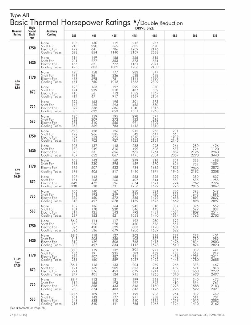
76 (131-110) © Rexnord Industries, LLC, 1998, 2006.
Type AB
Basic Thermal Horsepower Ratings �/Double Reduction
NominalRatios
HighSpeedShaftrpm
AuxiliaryCooling
DRIVE SIZE
385 405 425 445 465 485 505 525
5.06thru6.86
1750
None 103 130 119 212 257Shaft Fan 210 290 365 605 670Electric Fan 472 641 786 1209 2146Cooling Tubes 523 854 1140 2109 2568
1430
None 114 149 155 256 315Shaft Fan 201 277 353 573 654Electric Fan 456 621 772 1181 2071Cooling Tubes 493 803 1082 1986 2450
1170
None 120 158 177 283 347Shaft Fan 191 261 336 538 628Electric Fan 438 598 751 1144 1990Cooling Tubes 461 750 1018 1863 2309
870
None 123 163 192 299 370Shaft Fan 174 239 310 487 582Electric Fan 410 561 713 1082 1867Cooling Tubes 414 671 917 1669 2104
720
None 122 162 195 301 373Shaft Fan 163 225 293 456 550Electric Fan 392 538 686 1040 1815Cooling Tubes 385 622 853 1551 1963
580
None 120 159 195 298 371Shaft Fan 153 209 273 422 515Electric Fan 371 510 656 991 1702Cooling Tubes 353 569 783 1416 1810
7.59thru
10.29
1750
None 98.8 128 126 215 263 201Shaft Fan 192 266 335 542 647 665Electric Fan 409 553 675 1010 1843 1942Cooling Tubes 434 702 927 1622 2121 2145
1430
None 105 137 148 238 298 264 280 426Shaft Fan 180 249 316 499 608 637 794 1120Electric Fan 393 531 656 973 1764 1887 2126 2963Cooling Tubes 407 652 867 1475 2004 2057 2298 3443
1170
None 108 142 160 249 316 301 336 488Shaft Fan 168 230 295 459 570 604 752 1054Electric Fan 375 507 633 934 1685 1823 2065 2872Cooling Tubes 378 605 817 1410 1874 1945 2192 3308
870
None 107 142 168 253 325 329 380 537Shaft Fan 151 208 266 407 514 553 686 955Electric Fan 349 472 596 874 1571 1724 1962 2724Cooling Tubes 338 538 731 1256 1692 1775 2015 3067
720
None 106 140 167 250 324 336 392 549Shaft Fan 141 193 249 377 480 521 645 895Electric Fan 332 450 572 835 1499 1658 1891 2627Cooling Tubes 313 497 678 1159 1575 1669 1898 2897
580
None 102 136 164 245 318 337 396 552Shaft Fan 131 178 230 346 443 485 599 831Electric Fan 314 425 543 792 1421 1584 1809 2514Cooling Tubes 287 453 621 1058 1440 1534 1763 2703
11.39thru
17.09
1750
None 86.2 114 117 192 250 192Shaft Fan 160 226 278 450 576 557Electric Fan 326 450 529 803 1490 1531Cooling Tubes 326 536 679 1206 1639 1622
1430
None 88.5 118 127 202 266 229 273 401Shaft Fan 148 208 256 408 527 522 710 989Electric Fan 310 429 508 768 1415 1476 1814 2503Cooling Tubes 303 497 634 1115 1528 1540 1874 2820
1170
None 88.5 119 132 205 271 251 309 441Shaft Fan 136 191 235 371 482 488 662 917Electric Fan 294 407 487 731 1343 1418 1751 2411Cooling Tubes 281 460 589 1037 1422 1445 1780 2685
870
None 86.1 116 133 204 269 266 335 467Shaft Fan 121 169 209 323 424 439 594 818Electric Fan 271 376 453 679 1241 1330 1653 2272Cooling Tubes 249 405 524 915 1265 1310 1628 2497
720
None 83.7 113 131 199 264 267 340 472Shaft Fan 112 156 193 297 392 410 554 761Electric Fan 258 358 433 646 1180 1275 1588 2183Cooling Tubes 230 374 483 843 1176 1225 1522 2321
580
None 80.6 109 127 192 256 264 339 469Shaft Fan 101 143 177 271 358 379 511 701Electric Fan 243 338 410 610 1115 1213 1515 2083Cooling Tubes 218 340 441 765 1066 1124 1410 2162
(See � footnote on Page 78.)
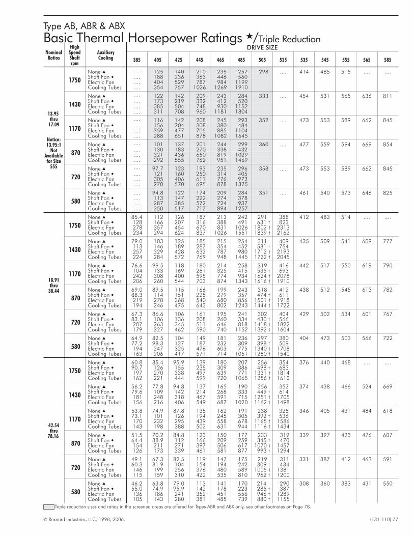
© Rexnord Industries, LLC, 1998, 2006. (131-110) 77
Type AB, ABR & ABX
Basic Thermal Horsepower Ratings �/Triple Reduction
NominalRatios
HighSpeedShaftrpm
AuxiliaryCooling
DRIVE SIZE
385 405 425 445 465 485 505 525 535 545 555 565 585
13.95thru
17.09
Notice:13.95:1
NotAvailablefor Size
555
1750
None � .... 125 140 210 235 257 298 .... 414 485 515 .... ....Shaft Fan � .... 188 236 363 446 560Electric Fan .... 404 529 787 984 1199Cooling Tubes .... 354 757 1026 1269 1910
1430
None � .... 122 142 209 243 284 333 .... 454 531 565 636 811Shaft Fan � .... 173 219 332 412 520Electric Fan .... 385 504 748 930 1152Cooling Tubes .... 311 708 960 1181 1804
1170
None � .... 116 142 208 245 293 352 .... 473 553 589 662 845Shaft Fan � .... 156 204 308 380 484Electric Fan .... 359 477 705 885 1104Cooling Tubes .... 288 651 878 1082 1645
870
None � .... 101 137 201 244 299 360 .... 477 559 594 669 854Shaft Fan � .... 130 183 270 338 432Electric Fan .... 321 436 650 819 1029Cooling Tubes .... 292 555 762 951 1469
720
None � .... 97.7 123 193 235 296 358 .... 473 553 589 662 845Shaft Fan � .... 121 160 250 314 405Electric Fan .... 305 406 611 776 972Cooling Tubes .... 270 570 695 878 1375
580
None � .... 94.8 122 174 209 284 351 .... 461 540 573 646 825Shaft Fan � .... 113 147 222 274 378Electric Fan .... 287 385 572 724 937Cooling Tubes .... 250 517 717 894 1257
18.91thru
38.44
1750
None � 85.4 112 126 187 213 242 291 388 412 483 514 .... ....Shaft Fan � 128 166 207 316 388 491 631 † 823Electric Fan 278 357 454 670 831 1026 1802 † 2313Cooling Tubes 234 294 624 837 1026 1551 1839 † 2162
1430
None � 79.0 103 125 185 215 254 311 409 435 509 541 609 777Shaft Fan � 113 146 189 287 354 452 581 † 754Electric Fan 257 329 428 632 787 980 1712 † 2193Cooling Tubes 224 284 572 769 948 1445 1722 † 2045
1170
None � 76.6 99.5 118 180 214 258 319 416 442 517 550 619 790Shaft Fan � 104 133 169 261 325 415 535 † 693Electric Fan 242 308 400 595 774 934 1624 † 2078Cooling Tubes 206 260 544 703 874 1343 1616 † 1910
870
None � 69.0 89.5 115 166 199 243 318 412 438 512 545 613 782Shaft Fan � 88.3 114 151 225 279 357 474 † 611Electric Fan 219 278 368 540 680 856 1501 † 1918Cooling Tubes 194 246 475 643 802 1243 1444 † 1722
720
None � 67.3 86.6 106 161 195 241 302 404 429 502 534 601 767Shaft Fan � 83.1 106 136 208 260 334 430 † 566Electric Fan 207 263 345 511 646 818 1418 † 1822Cooling Tubes 179 227 462 590 740 1152 1392 † 1604
580
None � 64.9 82.5 104 149 181 236 297 380 404 473 503 566 722Shaft Fan � 77.2 98.3 127 187 232 309 398 † 509Electric Fan 194 247 325 476 603 775 1340 † 1708Cooling Tubes 163 206 417 571 714 1051 1280 † 1540
42.54thru
78.16
1750
None � 60.8 85.4 95.9 139 180 207 256 354 376 440 468 .... ....Shaft Fan � 90.7 126 155 235 309 386 498 † 683Electric Fan 197 270 338 497 639 771 1331 † 1814Cooling Tubes 162 221 444 599 720 1065 1256 † 1610
1430
None � 56.2 77.8 94.8 137 165 190 256 352 374 438 466 524 669Shaft Fan � 79.6 109 142 214 268 333 449 † 614Electric Fan 181 248 318 467 591 715 1251 † 1705Cooling Tubes 156 216 406 549 687 1020 1162 † 1498
1170
None � 53.8 74.9 87.8 135 162 191 238 325 346 405 431 484 618Shaft Fan � 73.1 101 126 194 245 305 392 † 536Electric Fan 170 232 295 439 558 678 1165 † 1586Cooling Tubes 143 198 388 502 631 944 1116 † 1434
870
None � 51.5 70.2 84.8 123 150 177 233 319 339 397 423 476 607Shaft Fan � 64.4 88.9 112 166 209 259 345 † 470Electric Fan 154 211 271 397 506 617 1070 † 1457Cooling Tubes 126 173 339 461 581 877 993 † 1294
720
None � 49.1 67.3 82.5 119 147 175 219 311 331 387 412 463 591Shaft Fan � 60.3 81.9 104 154 194 242 309 † 434Electric Fan 146 199 256 376 480 589 1005 † 1381Cooling Tubes 115 159 310 422 535 810 962 † 1200
580
None � 46.2 63.8 79.0 113 141 170 214 290 308 360 383 431 550Shaft Fan � 55.0 74.9 95.9 142 178 223 285 † 387Electric Fan 136 186 241 352 451 556 946 † 1289Cooling Tubes 105 143 280 381 485 739 880 † 1155
Triple reduction sizes and ratios in the screened areas are offered for Types ABR and ABX only, see other footnotes on Page 78.
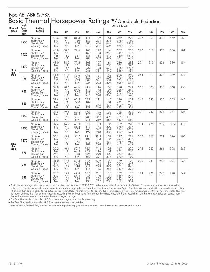
78 (131-110) © Rexnord Industries, LLC, 1998, 2006.
Type AB, ABR & ABX
Basic Thermal Horsepower Ratings �/Quadruple Reduction
NominalRatios
HighSpeedShaftrpm
AuxiliaryCooling
DRIVE SIZE
385 405 425 445 465 485 505 525 535 545 555 565 585
78.16thru
158.9
1750
None � 48.6 60.8 81.3 111 129 161 242 290 307 363 380 442 550Shaft Fan � NA NA 120 163 204 273 398 † 480Electric Fan 156 192 278 385 484 644 1181 † 1429Cooling Tubes NA NA NA 313 387 504 628 † 729
1430
None � 46.8 58.5 79.6 108 129 164 209 253 270 317 333 386 481Shaft Fan � NA NA 111 150 188 253 335 † 407Electric Fan 146 180 261 361 456 610 1080 † 1310Cooling Tubes NA NA NA 289 359 472 606 † 697
1170
None � 45.0 56.2 77.2 105 127 164 210 255 271 319 336 389 484Shaft Fan � NA NA 101 137 174 235 309 † 376Electric Fan 136 167 245 339 428 577 1015 † 1234Cooling Tubes NA NA NA 266 331 440 566 † 654
870
None � 41.5 51.5 72.5 98.9 121 159 205 249 264 311 327 379 472Shaft Fan � NA NA 90.0 122 154 209 276 † 335Electric Fan 123 151 223 309 391 531 926 † 1128Cooling Tubes NA NA NA 234 293 394 506 † 588
720
None � 39.8 48.6 69.6 94.2 116 155 198 241 257 302 318 368 458Shaft Fan � NA NA 84.0 113 143 195 256 † 312Electric Fan 116 142 209 291 369 503 873 † 1065Cooling Tubes NA NA NA 216 270 365 469 † 548
580
None � 37.4 45.6 65.5 88.9 111 148 190 232 246 290 305 353 440Shaft Fan � NA NA 77.0 104 131 181 235 † 288Electric Fan 108 132 196 272 345 472 817 † 999Cooling Tubes NA NA NA 197 246 334 430 † 504
175.9thru
357.5
1750
None � 38.6 49.1 62.6 87.8 106 139 185 223 239 280 296 341 424Shaft Fan � NA NA 89.5 125 160 222 308 † 371Electric Fan 122 150 201 285 367 498 916 † 1103Cooling Tubes NA NA NA 215 269 364 487 † 559
1430
None � 37.4 46.2 60.3 83.1 103 136 182 220 234 275 289 335 418Shaft Fan � NA NA 81.3 113 146 202 278 † 337Electric Fan 113 140 187 266 342 467 854 † 1029Cooling Tubes NA NA NA 197 248 338 452 † 521
1170
None � 35.1 43.9 56.7 79.6 98.3 132 177 214 228 267 281 326 405Shaft Fan � NA NA 73.7 102 133 184 253 † 307Electric Fan 105 129 175 249 321 439 798 † 962Cooling Tubes NA NA NA 181 228 313 418 † 482
870
None � 32.2 40.4 52.7 73.1 91.8 125 167 202 215 253 266 308 383Shaft Fan � NA NA 64.9 90.7 116 161 221 † 268Electric Fan 95.4 116 158 225 290 400 723 † 873Cooling Tubes NA NA NA 159 201 277 370 † 430
720
None � 31.0 37.4 50.3 69.6 87.2 120 159 192 205 241 253 294 365Shaft Fan � NA NA 60.0 83.0 108 150 204 † 247Electric Fan 89.5 109 148 211 273 377 679 † 823Cooling Tubes NA NA NA 146 185 256 343 † 398
580
None � 28.7 35.1 47.4 65.5 83.1 113 152 183 194 229 240 278 347Shaft Fan � NA NA 54.4 76.6 100 137 186 † 226Electric Fan 83.1 101 138 197 254 352 633 † 768Cooling Tubes NA NA NA 133 167 233 312 † 364
� Basic thermal ratings in hp are shown for an ambient temperature of 80°F (27°C) and at an altitude of sea level to 2500 feet. For other ambient temperatures, otheraltitudes, or special air velocity / inlet water temperature / duty cycle considerations, use thermal factors on Page 10 to determine an application adjusted thermal ratingwhich can then be compared to the actual power transmitted. Thermal ratings for cooling tubes are based on water inlet temperature of 70°F (21°C), and water flow ratesas shown on Page 12. For cooling capacity exceeding the methods listed for the gear drive size, ratio, and high speed shaft rpm that you have selected, consult yourRexnord representative for an external heat exchanger package.
� For Type ABX, apply a multiplier of 0.8 to thermal ratings with no auxiliary cooling.
� For Type ABX, apply a multiplier of 0.9 to thermal ratings with shaft fan.† Ratings shown for shaft fan, electric fan, and cooling tubes apply to Size 505AB only. Consult Factory for 505ABR and 505ABX.
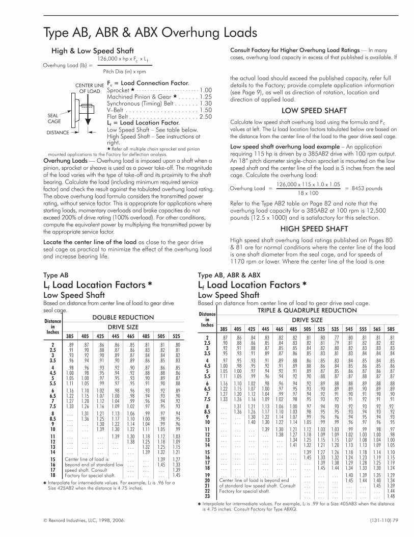
© Rexnord Industries, LLC, 1998, 2006. (131-110) 79
Type AB, ABR & ABX Overhung LoadsHigh & Low Speed Shaft
Overhung Load (lb) =126,000 x hp x F x L
Pitch D
c f
ia (in) x rpm
Fc = Load Connection Factor.Sprocket � . . . . . . . . . . . . . . . . . . . . . . . 1.00Machined Pinion & Gear � . . . . . . 1.25Synchronous (Timing) Belt . . . . . . . 1.30V–Belt . . . . . . . . . . . . . . . . . . . . . 1.50Flat Belt . . . . . . . . . . . . . . . . . . . . 2.50Lf = Load Location Factor.Low Speed Shaft – See table below.High Speed Shaft – See instructions atright.� Refer all multiple chain sprocket and pinion
mounted applications to the Factory for deflection analysis.
Overhung Loads — Overhung load is imposed upon a shaft when apinion, sprocket or sheave is used as a power take-off. The magnitudeof the load varies with the type of take-off and its proximity to the shaftbearing. Calculate the load (including minimum required servicefactor) and check the result against the tabulated overhung load rating.The above overhung load formula considers the transmitted powerrating, without service factor. This is appropriate for applications wherestarting loads, momentary overloads and brake capacities do notexceed 200% of drive rating (100% overload). For other conditions,compute the equivalent power by multiplying the transmitted power bythe appropriate service factor.
Locate the center line of the load as close to the gear driveseal cage as practical to minimize the effect of the overhung loadand increase bearing life.
Consult Factory for Higher Overhung Load Ratings — In many
cases, overhung load capacity in excess of that published is available. If
the actual load should exceed the published capacity, refer fulldetails to the Factory; provide complete application information(see Page 9), as well as direction of rotation, location anddirection of applied load.
LOW SPEED SHAFT
Calculate low speed shaft overhung load using the formula and Fc
values at left. The Lf load location factors tabulated below are based on
the distance from the center line of the load to the gear drive seal cage.
Low speed shaft overhung load example – An applicationrequiring 115 hp is driven by a 385AB2 drive with 100 rpm output.An 18” pitch diameter single-chain sprocket is mounted on the lowspeed shaft and the center line of the load is 5 inches from the sealcage. Calculate the overhung load:
Overhung Load =126,000 x 115 x 1.0 x 1.05
18 x 100= 8453 pounds
Refer to the Type AB2 table on Page 82 and note that theoverhung load capacity for a 385AB2 at 100 rpm is 12,500pounds (12.5 x 1000) and is satisfactory for this selection.
HIGH SPEED SHAFT
High speed shaft overhung load ratings published on Pages 80& 81 are for normal conditions where the center line of the loadis one shaft diameter from the seal cage, and for speeds of1170 rpm or lower. Where the center line of the load is one
DISTANCE
CENTER LINEOF LOAD
SEALCAGE
Type AB
Lf Load Location Factors �
Low Speed ShaftBased on distance from center line of load to gear driveseal cage.
Distancein
Inches
DOUBLE REDUCTION
DRIVE SIZE
385 405 425 445 465 485 505 525
2 .89 .87 .86 .86 .85 .81 .81 .802.5 .91 .90 .88 .87 .86 .83 .82 .813 .93 .92 .90 .89 .87 .84 .84 .82
3.5 .96 .94 .91 .90 .89 .86 .85 .83
4 .98 .96 .93 .92 .90 .87 .86 .854.5 1.00 .98 .95 .94 .92 .88 .88 .865 1.05 1.00 .97 .95 .93 .90 .89 .87
5.5 1.11 1.05 .99 .97 .95 .91 .90 .88
6 1.16 1.10 1.02 .98 .96 .93 .92 .896.5 1.22 1.15 1.07 1.00 .98 .94 .93 .907 1.27 1.20 1.12 1.04 .99 .96 .94 .92
7.5 1.33 1.26 1.16 1.09 1.02 .97 .95 .93
8 . . . 1.31 1.21 1.13 1.06 .99 .97 .948.5 . . . 1.36 1.25 1.17 1.10 1.00 .98 .959 . . . . . . 1.30 1.22 1.14 1.04 .99 .96
10 . . . . . . 1.39 1.30 1.22 1.11 1.05 .99
11 . . . . . . . . . 1.39 1.30 1.18 1.12 1.0312 . . . . . . . . . . . . 1.38 1.25 1.18 1.0913 . . . . . . . . . . . . . . . 1.32 1.25 1.1514 . . . . . . . . . . . . . . . 1.39 1.32 1.21
15 Center line of load isbeyond end of standard lowspeed shaft. ConsultFactory for special shaft.
. . . . . . 1.39 1.2716 . . . . . . 1.45 1.3317 . . . . . . . . . 1.3918 . . . . . . . . . 1.45
� Interpolate for intermediate values. For example, Lf is .96 for aSize 425AB2 when the distance is 4.75 inches.
Type AB, ABR & ABX
Lf Load Location Factors �
Low Speed ShaftBased on distance from center line of load to gear drive seal cage.
Distancein
Inches
TRIPLE & QUADRUPLE REDUCTION
DRIVE SIZE
385 405 425 445 465 485 505 525 535 545 555 565 585
2 .87 .86 .84 .83 .82 .82 .81 .80 .77 .80 .81 .81 .812.5 .90 .88 .86 .85 .84 .83 .82 .81 .79 .81 .82 .82 .823 .92 .91 .88 .87 .85 .85 .84 .82 .80 .82 .83 .83 .83
3.5 .95 .93 .91 .89 .87 .86 .85 .83 .81 .83 .84 .84 .84
4 .97 .95 .93 .91 .89 .88 .86 .85 .83 .84 .85 .84 .854.5 1.00 .98 .95 .92 .91 .89 .88 .86 .84 .85 .86 .85 .865 1.05 1.00 .97 .94 .92 .91 .89 .87 .85 .86 .87 .86 .87
5.5 1.11 1.05 .99 .96 .94 .92 .90 .88 .87 .87 .88 .87 .87
6 1.16 1.10 1.02 .98 .96 .94 .92 .89 .88 .88 .89 .88 .886.5 1.22 1.15 1.07 1.00 .97 .95 .93 .90 .89 .89 .90 .89 .897 1.27 1.20 1.12 1.04 .99 .97 .94 .92 .91 .90 .91 .90 .90
7.5 1.33 1.26 1.16 1.09 1.02 .98 .95 .93 .92 .91 .92 .91 .91
8 . . . 1.31 1.21 1.13 1.06 1.00 .97 .94 .93 .92 .93 .92 .928.5 . . . 1.36 1.26 1.17 1.10 1.03 .98 .95 .95 .93 .94 .93 .929 . . . . . . 1.30 1.22 1.14 1.07 .99 .96 .96 .94 .95 .94 .93
10 . . . . . . 1.40 1.30 1.22 1.14 1.05 .99 .99 .96 .97 .96 .95
11 . . . . . . . . . 1.39 1.30 1.21 1.12 1.03 1.03 .99 .99 .98 .9712 . . . . . . . . . . . . 1.38 1.27 1.18 1.09 1.09 1.02 1.03 1.00 .9813 . . . . . . . . . . . . . . . 1.34 1.25 1.15 1.15 1.07 1.08 1.04 1.0014 . . . . . . . . . . . . . . . 1.41 1.32 1.21 1.20 1.13 1.13 1.09 1.05
15 . . . . . . . . . . . . . . . . . . 1.39 1.27 1.26 1.18 1.18 1.14 1.1016 . . . . . . . . . . . . . . . . . . 1.45 1.33 1.32 1.24 1.23 1.19 1.1517 . . . . . . . . . . . . . . . . . . . . . 1.39 1.38 1.29 1.28 1.25 1.1918 . . . . . . . . . . . . . . . . . . . . . 1.45 1.44 1.34 1.33 1.30 1.24
19 . . . . . . . . . . . . . . . . . . . . . . . . . . . 1.40 1.39 1.35 1.2920 Center line of load is beyond end
of standard low speed shaft. ConsultFactory for special shaft.
. . . . . . . . . 1.45 1.44 1.40 1.3421 . . . . . . . . . . . . . . . 1.45 1.3922 . . . . . . . . . . . . . . . . . . 1.4423 . . . . . . . . . . . . . . . . . . 1.48
� Interpolate for intermediate values. For example, Lf is .99 for a Size 405AB3 when the distanceis 4.75 inches. Consult Factory for Type ABXQ.

80 (131-110) © Rexnord Industries, LLC, 1998, 2006.
Type AB
High Speed Shaft Overhung Load �/Pounds
HighSpeedShaftrpm
Nom.Ratio±4%
Approx.Low
SpeedShaftrpm
DOUBLE REDUCTION
DRIVE SIZE
385 405 425 445 465 485 505 525
1170
5.06 230 1600 2000 2500 3000 14505.60 210 1600 2000 2500 3000 14506.20 190 1600 2000 2500 3000 1450
6.86 170 1600 2000 2500 3000 14507.59 155 1600 2000 2500 3000 1790 4000 4700 54008.40 140 1600 2000 2500 3000 2620 4000 4700 5400
9.30 125 1600 2000 2500 3000 3340 4000 4700 540010.29 115 1600 2000 2500 3000 3080 4000 4700 540011.39 100 1600 2000 2500 3000 3500 4000 4700 5400
870
5.06 175 1600 2000 2500 3000 19805.60 155 1600 2000 2500 3000 19806.20 140 1600 2000 2500 3000 1980
6.86 130 1600 2000 2500 3000 19807.59 115 1600 2000 2500 3000 1980 4000 4700 54008.40 105 1600 2000 2500 3000 3030 4000 4700 5400
9.30 95 1600 2000 2500 3000 3500 4000 4700 540010.29 85 1600 2000 2500 3000 3430 4000 4700 540011.39 77 1600 2000 2500 3000 3500 4000 4700 5400
720
5.06 140 1600 2000 2500 3000 24205.60 130 1600 2000 2500 3000 25806.20 115 1600 2000 2500 3000 2420
6.86 105 1600 2000 2500 3000 24207.59 95 1600 2000 2500 3000 2420 4000 4700 54008.40 85 1600 2000 2500 3000 3500 4000 4700 54009.30 77 1600 2000 2500 3000 3500 4000 4700 5400
580
5.06 115 1600 2000 2500 3000 31005.60 105 1600 2000 2500 3000 33406.20 95 1600 2000 2500 3000 3010
6.86 85 1600 2000 2500 3000 30107.59 77 1600 2000 2500 3000 3080 4000 4700 54008.40 70 1600 2000 2500 3000 3500 4000 4700 5400
Type AB, ABR & ABX
High Speed Shaft Overhung Load �/Pounds
HighSpeedShaftrpm
NominalRatio±5%
Approx.Low
SpeedShaftrpm
QUADRUPLE REDUCTION
DRIVE SIZE
385 405 425 445 465 485 505 525 535 545 555 565 585
117078.16 15.0 1300 ‡ 910 1300 1600 2000 2500 3000 3500 3500 4000 4000 4700 395086.50 13.5 700 980 1300 1600 2000 2500 3000 3500 3500 4000 4000 4700 450095.73 12.0 700 1000 1300 1600 2000 2500 3000 3500 3500 4000 4000 4700 4700
87078.16 11.0 1300 ‡ 1000 1300 1600 2000 2500 3000 3500 3500 4000 4000 4700 470086.50 10.0 700 1000 1300 1600 2000 2500 3000 3500 3500 4000 4000 4700 4700
72078.16 9.1 1300 ‡ 1000 1300 1600 2000 2500 3000 3500 3500 4000 4000 4700 470086.50 8.3 700 1000 1300 1600 2000 2500 3000 3500 3500 4000 4000 4700 4700
58078.16 7.5 1300 ‡ 1000 1300 1600 2000 2500 3000 3500 3500 4000 4000 4700 470086.50 6.8 700 1000 1300 1600 2000 2500 3000 3500 3500 4000 4000 4700 4700
� For loads applied one shaft diameter from seal cage and speeds of 1170 rpm or lower. In each High Speed Shaft rpm section, the last overhung load value applies to all ofthe higher ratios of that gear reduction. Published ratings are based on a combination of the most unfavorable conditions of loading. Consult Factory for ratings of driveswith fans.
‡ Size 385 rating at 78.16:1 is for triple reduction.
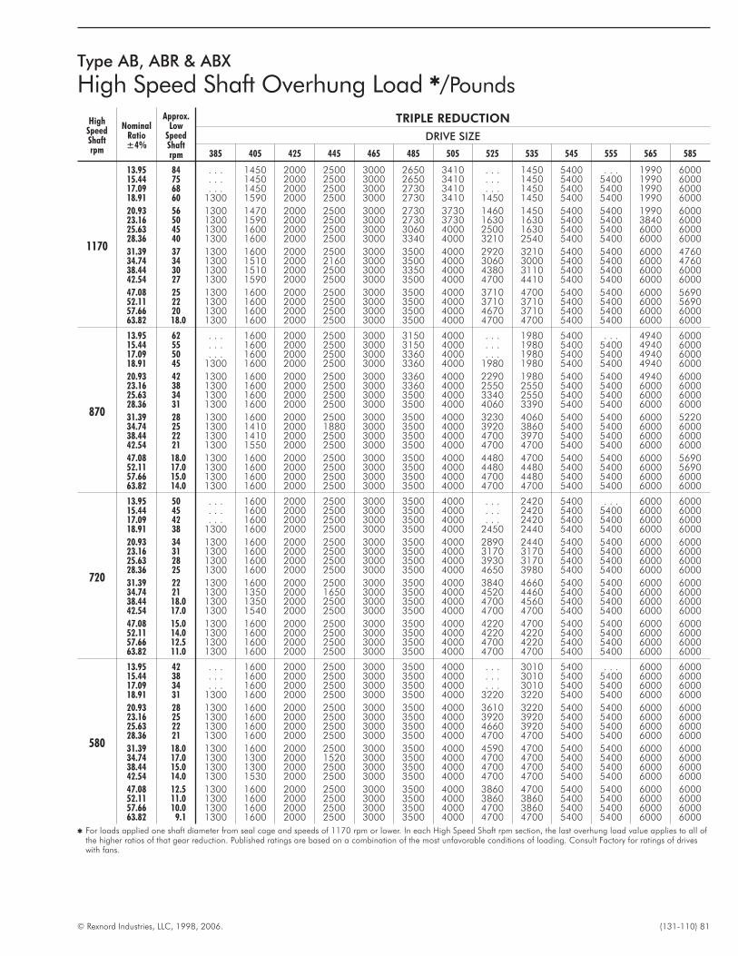
© Rexnord Industries, LLC, 1998, 2006. (131-110) 81
Type AB, ABR & ABX
High Speed Shaft Overhung Load �/Pounds
HighSpeedShaftrpm
NominalRatio±4%
Approx.Low
SpeedShaftrpm
TRIPLE REDUCTION
DRIVE SIZE
385 405 425 445 465 485 505 525 535 545 555 565 585
1170
13.95 84 . . . 1450 2000 2500 3000 2650 3410 . . . 1450 5400 . . . 1990 600015.44 75 . . . 1450 2000 2500 3000 2650 3410 . . . 1450 5400 5400 1990 600017.09 68 . . . 1450 2000 2500 3000 2730 3410 . . . 1450 5400 5400 1990 600018.91 60 1300 1590 2000 2500 3000 2730 3410 1450 1450 5400 5400 1990 6000
20.93 56 1300 1470 2000 2500 3000 2730 3730 1460 1450 5400 5400 1990 600023.16 50 1300 1590 2000 2500 3000 2730 3730 1630 1630 5400 5400 3840 600025.63 45 1300 1600 2000 2500 3000 3060 4000 2500 1630 5400 5400 6000 600028.36 40 1300 1600 2000 2500 3000 3340 4000 3210 2540 5400 5400 6000 6000
31.39 37 1300 1600 2000 2500 3000 3500 4000 2920 3210 5400 5400 6000 476034.74 34 1300 1510 2000 2160 3000 3500 4000 3060 3000 5400 5400 6000 476038.44 30 1300 1510 2000 2500 3000 3350 4000 4380 3110 5400 5400 6000 600042.54 27 1300 1590 2000 2500 3000 3500 4000 4700 4410 5400 5400 6000 6000
47.08 25 1300 1600 2000 2500 3000 3500 4000 3710 4700 5400 5400 6000 569052.11 22 1300 1600 2000 2500 3000 3500 4000 3710 3710 5400 5400 6000 569057.66 20 1300 1600 2000 2500 3000 3500 4000 4670 3710 5400 5400 6000 600063.82 18.0 1300 1600 2000 2500 3000 3500 4000 4700 4700 5400 5400 6000 6000
870
13.95 62 . . . 1600 2000 2500 3000 3150 4000 . . . 1980 5400 . . . 4940 600015.44 55 . . . 1600 2000 2500 3000 3150 4000 . . . 1980 5400 5400 4940 600017.09 50 . . . 1600 2000 2500 3000 3360 4000 . . . 1980 5400 5400 4940 600018.91 45 1300 1600 2000 2500 3000 3360 4000 1980 1980 5400 5400 4940 6000
20.93 42 1300 1600 2000 2500 3000 3360 4000 2290 1980 5400 5400 4940 600023.16 38 1300 1600 2000 2500 3000 3360 4000 2550 2550 5400 5400 6000 600025.63 34 1300 1600 2000 2500 3000 3500 4000 3340 2550 5400 5400 6000 600028.36 31 1300 1600 2000 2500 3000 3500 4000 4060 3390 5400 5400 6000 6000
31.39 28 1300 1600 2000 2500 3000 3500 4000 3230 4060 5400 5400 6000 522034.74 25 1300 1410 2000 1880 3000 3500 4000 3920 3860 5400 5400 6000 600038.44 22 1300 1410 2000 2500 3000 3500 4000 4700 3970 5400 5400 6000 600042.54 21 1300 1550 2000 2500 3000 3500 4000 4700 4700 5400 5400 6000 6000
47.08 18.0 1300 1600 2000 2500 3000 3500 4000 4480 4700 5400 5400 6000 569052.11 17.0 1300 1600 2000 2500 3000 3500 4000 4480 4480 5400 5400 6000 569057.66 15.0 1300 1600 2000 2500 3000 3500 4000 4700 4480 5400 5400 6000 600063.82 14.0 1300 1600 2000 2500 3000 3500 4000 4700 4700 5400 5400 6000 6000
720
13.95 50 . . . 1600 2000 2500 3000 3500 4000 . . . 2420 5400 . . . 6000 600015.44 45 . . . 1600 2000 2500 3000 3500 4000 . . . 2420 5400 5400 6000 600017.09 42 . . . 1600 2000 2500 3000 3500 4000 . . . 2420 5400 5400 6000 600018.91 38 1300 1600 2000 2500 3000 3500 4000 2450 2440 5400 5400 6000 6000
20.93 34 1300 1600 2000 2500 3000 3500 4000 2890 2440 5400 5400 6000 600023.16 31 1300 1600 2000 2500 3000 3500 4000 3170 3170 5400 5400 6000 600025.63 28 1300 1600 2000 2500 3000 3500 4000 3930 3170 5400 5400 6000 600028.36 25 1300 1600 2000 2500 3000 3500 4000 4650 3980 5400 5400 6000 6000
31.39 22 1300 1600 2000 2500 3000 3500 4000 3840 4660 5400 5400 6000 600034.74 21 1300 1350 2000 1650 3000 3500 4000 4520 4460 5400 5400 6000 600038.44 18.0 1300 1350 2000 2500 3000 3500 4000 4700 4560 5400 5400 6000 600042.54 17.0 1300 1540 2000 2500 3000 3500 4000 4700 4700 5400 5400 6000 6000
47.08 15.0 1300 1600 2000 2500 3000 3500 4000 4220 4700 5400 5400 6000 600052.11 14.0 1300 1600 2000 2500 3000 3500 4000 4220 4220 5400 5400 6000 600057.66 12.5 1300 1600 2000 2500 3000 3500 4000 4700 4220 5400 5400 6000 600063.82 11.0 1300 1600 2000 2500 3000 3500 4000 4700 4700 5400 5400 6000 6000
580
13.95 42 . . . 1600 2000 2500 3000 3500 4000 . . . 3010 5400 . . . 6000 600015.44 38 . . . 1600 2000 2500 3000 3500 4000 . . . 3010 5400 5400 6000 600017.09 34 . . . 1600 2000 2500 3000 3500 4000 . . . 3010 5400 5400 6000 600018.91 31 1300 1600 2000 2500 3000 3500 4000 3220 3220 5400 5400 6000 6000
20.93 28 1300 1600 2000 2500 3000 3500 4000 3610 3220 5400 5400 6000 600023.16 25 1300 1600 2000 2500 3000 3500 4000 3920 3920 5400 5400 6000 600025.63 22 1300 1600 2000 2500 3000 3500 4000 4660 3920 5400 5400 6000 600028.36 21 1300 1600 2000 2500 3000 3500 4000 4700 4700 5400 5400 6000 6000
31.39 18.0 1300 1600 2000 2500 3000 3500 4000 4590 4700 5400 5400 6000 600034.74 17.0 1300 1300 2000 1520 3000 3500 4000 4700 4700 5400 5400 6000 600038.44 15.0 1300 1300 2000 2500 3000 3500 4000 4700 4700 5400 5400 6000 600042.54 14.0 1300 1530 2000 2500 3000 3500 4000 4700 4700 5400 5400 6000 6000
47.08 12.5 1300 1600 2000 2500 3000 3500 4000 3860 4700 5400 5400 6000 600052.11 11.0 1300 1600 2000 2500 3000 3500 4000 3860 3860 5400 5400 6000 600057.66 10.0 1300 1600 2000 2500 3000 3500 4000 4700 3860 5400 5400 6000 600063.82 9.1 1300 1600 2000 2500 3000 3500 4000 4700 4700 5400 5400 6000 6000
� For loads applied one shaft diameter from seal cage and speeds of 1170 rpm or lower. In each High Speed Shaft rpm section, the last overhung load value applies to all ofthe higher ratios of that gear reduction. Published ratings are based on a combination of the most unfavorable conditions of loading. Consult Factory for ratings of driveswith fans.
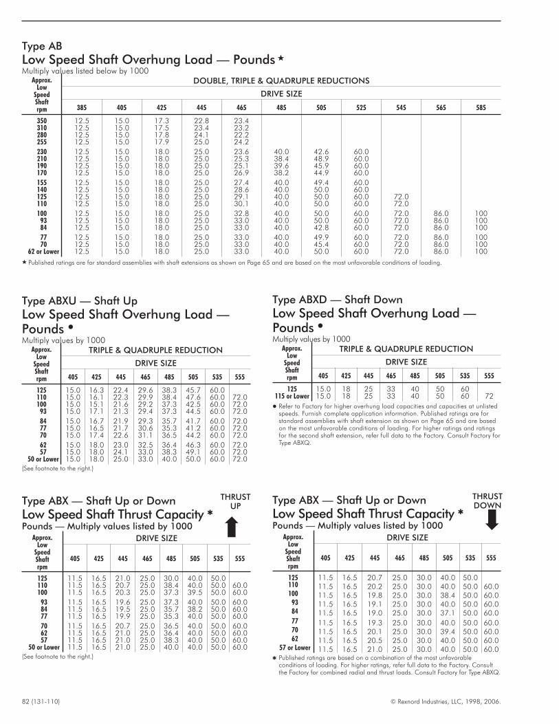
82 (131-110) © Rexnord Industries, LLC, 1998, 2006.
Type ABX — Shaft Up or Down
Low Speed Shaft Thrust Capacity �
Pounds — Multiply values listed by 1000Approx.
LowSpeedShaftrpm
DRIVE SIZE
405 425 445 465 485 505 535 555
125 11.5 16.5 21.0 25.0 30.0 40.0 50.0110 11.5 16.5 20.7 25.0 38.4 40.0 50.0 60.0100 11.5 16.5 20.3 25.0 37.3 39.5 50.0 60.0
93 11.5 16.5 19.6 25.0 37.3 40.0 50.0 60.084 11.5 16.5 19.5 25.0 35.7 38.2 50.0 60.077 11.5 16.5 19.9 25.0 35.3 40.0 50.0 60.0
70 11.5 16.5 20.7 25.0 36.5 40.0 50.0 60.062 11.5 16.5 21.0 25.0 36.4 40.0 50.0 60.057 11.5 16.5 21.0 25.0 38.3 40.0 50.0 60.0
50 or Lower 11.5 16.5 21.0 25.0 40.0 40.0 50.0 60.0(See footnote to the right.)
Type ABX — Shaft Up or Down
Low Speed Shaft Thrust Capacity �
Pounds — Multiply values listed by 1000Approx.
LowSpeedShaftrpm
DRIVE SIZE
405 425 445 465 485 505 535 555
125 11.5 16.5 20.7 25.0 30.0 40.0 50.0110 11.5 16.5 20.2 25.0 30.0 40.0 50.0 60.0100 11.5 16.5 19.8 25.0 30.0 38.4 50.0 60.0
93 11.5 16.5 19.1 25.0 30.0 40.0 50.0 60.084 11.5 16.5 19.0 25.0 30.0 37.1 50.0 60.077 11.5 16.5 19.3 25.0 30.0 40.0 50.0 60.070 11.5 16.5 20.1 25.0 30.0 39.4 50.0 60.062 11.5 16.5 20.5 25.0 30.0 40.0 50.0 60.0
57 or Lower 11.5 16.5 21.0 25.0 30.0 40.0 50.0 60.0� Published ratings are based on a combination of the most unfavorable
conditions of loading. For higher ratings, refer full data to the Factory. Consultthe Factory for combined radial and thrust loads. Consult Factory for Type ABXQ.
�
THRUSTDOWN
Type AB
Low Speed Shaft Overhung Load — Pounds �
Multiply values listed below by 1000Approx.
LowSpeedShaftrpm
DOUBLE, TRIPLE & QUADRUPLE REDUCTIONS
DRIVE SIZE
385 405 425 445 465 485 505 525 545 565 585
350 12.5 15.0 17.3 22.8 23.4310 12.5 15.0 17.5 23.4 23.2280 12.5 15.0 17.8 24.1 22.2255 12.5 15.0 17.9 25.0 24.2
230 12.5 15.0 18.0 25.0 23.6 40.0 42.6 60.0210 12.5 15.0 18.0 25.0 25.3 38.4 48.9 60.0190 12.5 15.0 18.0 25.0 25.1 39.6 45.9 60.0170 12.5 15.0 18.0 25.0 26.9 38.2 44.9 60.0
155 12.5 15.0 18.0 25.0 27.4 40.0 49.4 60.0140 12.5 15.0 18.0 25.0 28.6 40.0 50.0 60.0125 12.5 15.0 18.0 25.0 29.1 40.0 50.0 60.0 72.0110 12.5 15.0 18.0 25.0 30.1 40.0 50.0 60.0 72.0
100 12.5 15.0 18.0 25.0 32.8 40.0 50.0 60.0 72.0 86.0 10093 12.5 15.0 18.0 25.0 33.0 40.0 50.0 60.0 72.0 86.0 10084 12.5 15.0 18.0 25.0 33.0 40.0 42.8 60.0 72.0 86.0 100
77 12.5 15.0 18.0 25.0 33.0 40.0 49.9 60.0 72.0 86.0 10070 12.5 15.0 18.0 25.0 33.0 40.0 45.4 60.0 72.0 86.0 100
62 or Lower 12.5 15.0 18.0 25.0 33.0 40.0 50.0 60.0 72.0 86.0 100
� Published ratings are for standard assemblies with shaft extensions as shown on Page 65 and are based on the most unfavorable conditions of loading.
Type ABXU — Shaft Up
Low Speed Shaft Overhung Load —Pounds �Multiply values by 1000
Approx.Low
SpeedShaftrpm
TRIPLE & QUADRUPLE REDUCTION
DRIVE SIZE
405 425 445 465 485 505 535 555
125 15.0 16.3 22.4 29.6 38.3 45.7 60.0110 15.0 16.1 22.3 29.9 38.4 47.6 60.0 72.0100 15.0 15.1 21.6 29.2 37.3 42.5 60.0 72.0
93 15.0 17.1 21.3 29.4 37.3 44.5 60.0 72.0
84 15.0 16.7 21.9 29.3 35.7 41.7 60.0 72.077 15.0 16.5 21.7 30.6 35.3 41.2 60.0 72.070 15.0 17.4 22.6 31.1 36.5 44.2 60.0 72.0
62 15.0 18.0 23.0 32.5 36.4 46.3 60.0 72.057 15.0 18.0 24.1 33.0 38.3 49.1 60.0 72.0
50 or Lower 15.0 18.0 25.0 33.0 40.0 50.0 60.0 72.0(See footnote to the right.)
Type ABXD — Shaft Down
Low Speed Shaft Overhung Load —Pounds �Multiply values by 1000
Approx.Low
SpeedShaftrpm
TRIPLE & QUADRUPLE REDUCTION
DRIVE SIZE
405 425 445 465 485 505 535 555
125 15.0 18 25 33 40 50 60115 or Lower 15.0 18 25 33 40 50 60 72
� Refer to Factory for higher overhung load capacities and capacities at unlistedspeeds. Furnish complete application information. Published ratings are forstandard assemblies with shaft extension as shown on Page 65 and are basedon the most unfavorable conditions of loading. For higher ratings and ratingsfor the second shaft extension, refer full data to the Factory. Consult Factory forType ABXQ.
THRUSTUP
�
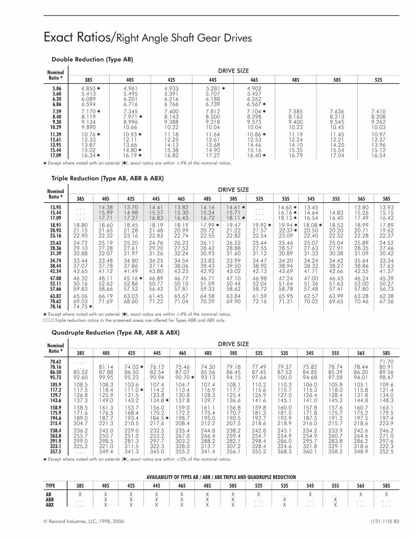
© Rexnord Industries, LLC, 1998, 2006. (131-110) 83
Exact Ratios/Right Angle Shaft Gear Drives
Double Reduction (Type AB)
NominalRatio �
DRIVE SIZE
385 405 425 445 465 485 505 525
5.06 4.850 � 4.961 4.933 5.281 � 4.9025.60 5.413 5.495 5.391 5.707 5.4276.20 6.089 6.201 6.216 6.188 6.2626.86 6.594 6.716 6.766 6.739 6.567 �
7.59 7.170 � 7.345 7.400 7.812 7.104 � 7.585 7.636 7.4108.40 8.119 7.971 � 8.143 8.500 8.298 8.162 8.213 8.2089.30 9.134 8.996 9.388 9.218 9.575 9.400 9.545 9.262
10.29 9.890 10.66 10.22 10.04 10.04 10.23 10.45 10.03
11.39 10.76 � 10.93 � 11.18 11.64 10.86 � 11.19 11.45 10.9712.61 12.33 12.11 12.25 12.61 12.53 12.24 12.21 12.3713.95 13.87 13.66 14.13 13.68 14.46 14.10 14.20 13.9615.44 15.02 14.80 � 15.38 14.90 15.16 15.35 15.54 15.1217.09 16.34 � 16.19 � 16.82 17.27 16.40 � 16.79 17.04 16.54
� Except where noted with an asterisk (�), exact ratios are within ±4% of the nominal ratios.
Triple Reduction (Type AB, ABR & ABX)
NominalRatio �
DRIVE SIZE
385 405 425 445 465 485 505 525 535 545 555 565 585
13.95 . . . 14.38 13.70 14.41 13.82 14.16 14.61 � . . . 14.65 � 13.45 . . . 13.80 13.9315.44 . . . 15.99 14.98 15.57 15.30 15.24 15.71 . . . 16.16 � 14.64 14.83 15.26 15.1517.09 . . . 17.71 17.27 16.83 16.43 16.72 18.11 � . . . 18.13 � 16.54 16.40 17.49 16.42
18.91 18.80 18.60 18.45 18.19 18.19 17.99 � 19.47 19.92 � 19.94 � 18.08 � 18.53 18.99 17.8920.93 21.15 21.65 21.28 21.48 20.99 20.72 21.22 21.57 22.37 � 20.50 20.20 20.71 19.6223.16 22.90 22.32 23.16 22.83 22.74 22.55 22.82 22.54 23.09 22.40 22.52 22.28 22.37
25.63 24.72 25.19 25.20 24.76 26.23 26.11 26.52 25.44 25.46 25.07 25.04 25.89 24.5228.36 29.10 27.28 27.61 29.20 27.52 28.42 28.88 27.55 28.57 27.63 27.91 28.35 27.4631.39 30.88 32.07 31.97 31.26 32.24 30.93 31.60 31.12 30.89 31.33 30.38 31.09 30.42
34.74 33.44 33.48 34.80 34.25 34.54 33.83 33.99 34.47 34.20 34.24 34.42 35.64 33.3438.44 37.07 37.78 37.86 37.14 38.06 39.43 39.50 38.90 38.94 38.32 38.27 38.86 37.6342.54 43.65 41.12 41.49 43.80 43.23 42.92 43.02 42.13 43.69 41.71 42.66 42.55 41.37
47.08 46.32 48.11 45.16 � 46.89 46.77 46.71 47.10 46.98 47.24 47.00 46.43 46.24 45.3952.11 50.16 52.62 52.86 50.77 50.10 51.09 50.44 52.04 51.64 51.36 51.63 53.00 50.2757.66 59.83 58.66 57.52 56.42 57.81 59.33 58.62 58.72 58.78 57.48 57.41 57.80 56.73
63.82 65.06 66.19 63.03 61.45 65.67 64.58 63.84 61.59 65.95 62.57 63.99 63.28 62.3870.62 69.03 71.69 68.60 71.22 71.04 70.29 69.90 72.16 71.31 70.02 69.65 70.46 67.5678.16 74.75 �
� Except where noted with an asterisk (�), exact ratios are within ±4% of the nominal ratios.
Triple reduction ratios in the screened areas are offered for Types ABR and ABX only.
Quadruple Reduction (Type AB, ABR & ABX)
NominalRatio �
DRIVE SIZE
385 405 425 445 465 485 505 525 535 545 555 565 585
70.62 . . . . . . . . . . . . . . . . . . . . . . . . . . . . . . . . . . . . 71.7078.16 . . . 81.14 74.03 � 76.12 75.46 74.30 79.18 77.49 79.37 75.82 78.74 78.44 80.9186.50 85.52 87.88 86.50 82.54 87.07 85.56 86.45 87.45 87.53 84.85 85.39 86.20 89.5695.73 92.60 99.95 95.23 90.94 90.70 � 93.13 94.15 97.64 100.0 94.68 97.58 94.01 98.47
105.9 108.5 108.3 103.6 107.4 104.7 107.4 108.1 110.2 110.3 106.0 105.8 105.1 109.6117.2 117.5 118.4 111.0 � 114.2 113.4 116.9 117.7 115.6 115.7 115.3 118.0 115.8 121.4129.7 126.8 125.9 131.5 123.8 130.8 128.3 125.4 126.9 127.0 126.4 128.4 131.8 134.0143.6 137.3 149.0 143.2 134.8 � 137.8 139.7 136.6 141.6 145.1 141.0 145.3 144.8 148.3
158.9 158.5 161.3 153.7 156.0 159.0 161.1 156.8 159.8 160.0 157.8 157.6 160.7 163.1175.9 171.6 176.5 168.4 170.2 172.2 175.4 170.7 181.3 181.5 171.8 175.7 175.2 179.5194.6 189.0 187.7 193.4 184.5 � 198.7 195.0 190.5 192.7 192.9 187.5 191.2 197.5 197.4215.4 204.7 221.3 210.5 217.6 208.4 212.2 207.5 218.6 218.9 216.0 215.7 218.6 223.9
238.4 236.2 242.0 229.0 232.5 235.4 244.8 238.2 242.8 243.1 234.2 233.9 242.6 246.2263.8 255.7 250.7 251.0 253.2 267.0 266.4 259.4 254.7 254.9 254.9 260.7 264.6 271.0291.9 299.0 298.5 281.3 297.7 303.2 288.2 282.1 298.4 286.0 295.7 283.8 286.2 297.6323.1 325.2 321.0 311.5 322.3 328.0 313.7 307.2 328.4 324.6 321.8 329.1 318.6 322.3357.5 . . . 349.4 341.3 345.0 355.2 341.4 356.1 355.2 368.3 360.1 358.2 348.9 352.5
� Except where noted with an asterisk (�), exact ratios are within ±5% of the nominal ratios.
AVAILABILITY OF TYPES AB / ABR / ABX TRIPLE AND QUADRUPLE REDUCTION
TYPE 385 405 425 445 465 485 505 525 535 545 555 565 585
AB X X X X X X X X . . . X . . . X XABR . . . X X X X X X . . . X . . . X . . . . . .ABX . . . X X X X X X . . . X . . . X . . . . . .
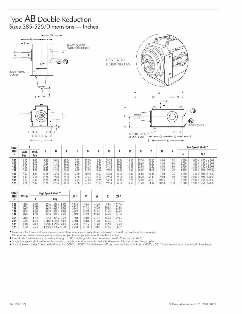
84 (131-110) © Rexnord Industries, LLC, 1998, 2006.
Type AB Double ReductionSizes 385-525/Dimensions — Inches
DRIVESIZE
�
A
B D E F G J K L M N O Q R
Low Speed Shaft �
W/OFan
WithFan
S Key
385 5.00 3.06 7.88 10.06 20.06 1.62 12.50 8.44 28.24 23.76 10.50 19.10 34.60 5.00 .94 4.500 1.000 x 1.000 x 6.500405 5.50 3.26 8.66 11.20 23.00 2.00 14.00 9.20 32.00 25.30 11.25 20.60 38.50 5.50 1.06 5.000 1.250 x 1.250 x 7.500425 7.00 4.12 10.06 12.74 25.00 1.62 15.75 11.12 34.74 27.50 12.25 22.90 44.60 6.00 1.06 5.750 1.500 x 1.500 x 8.000445 7.50 4.38 11.38 14.50 27.70 2.50 17.50 12.00 40.00 32.20 14.60 26.30 51.18 7.00 1.20 6.500 1.500 x 1.500 x 10.000
465 7.50 4.38 12.68 16.50 31.00 2.50 20.50 14.00 46.00 33.00 15.00 28.60 54.82 7.00 1.26 7.250 1.750 x 1.500 x 11.000485 9.00 5.56 14.88 19.00 35.00 2.50 22.25 16.00 49.50 35.00 15.40 30.70 62.40 9.00 1.50 8.500 2.000 x 1.500 x 13.000505 10.00 6.32 16.18 20.50 38.00 2.75 24.00 17.25 53.50 39.50 17.25 33.60 67.10 10.26 1.75 9.250 2.500 x 1.750 x 14.000525 11.24 7.32 18.38 22.50 41.00 2.50 27.25 20.00 59.50 42.00 18.50 37.20 71.32 10.50 2.10 10.500 2.500 x 1.750 x 16.000
DRIVESIZE
�
Wt-lbHigh Speed Shaft �
U � V W X XX �T Key
385 1530 2.500 .625 x .625 x 4.500 1.125 9.80 44.60 9.96 21.10405 2020 2.750 .625 x .625 x 5.000 1.125 11.12 49.70 10.56 21.58425 2810 3.500 .875 x .875 x 6.000 1.250 12.50 57.34 11.78 23.78445 4320 3.750 .875 x .875 x 6.500 1.500 14.50 65.68 13.78 27.18
465 5400 3.750 .875 x .875 x 6.500 1.500 16.00 71.32 14.24 29.66485 6990 4.500 1.000 x 1.000 x 8.000 2.000 18.00 81.40 14.36 31.24505 10300 5.000 1.250 x 1.250 x 9.000 2.250 19.75 87.60 15.90 34.60525 12810 5.500 1.250 x 1.250 x 10.000 2.250 21.10 93.82 17.56 38.12
� Drives are for horizontal floor mounted operation unless specifically stated otherwise. Consult Factory for other mountings.Dimensions are for reference only and are subject to change without notice unless certified.
� Use Grade 5 fasteners for diameters through 1.50”. For larger diameter fasteners, use ASTM A-354 Grade BC.� Single low speed shaft extension is standard; double extension, as indicated with dimension XX, is an extra charge option.� Shaft diameters under 3” are held to limits of +.0000”, –.0005”. Shaft diameters 3” and over are held to limits of +.000”, –.001”. Shaft keyseat depth is one-half of key height.
W
O D
1.2
E
V
G
A
INSPECTIONCOVER
SHAFT GUARD(WHEN REQUIRED)
L
M M
B
N X
XX
T
F K
G F
BOTH ENDS
6-HOLES FORU DIA. BOLT
J
S
R
DRIVE WITHCOOLING FAN
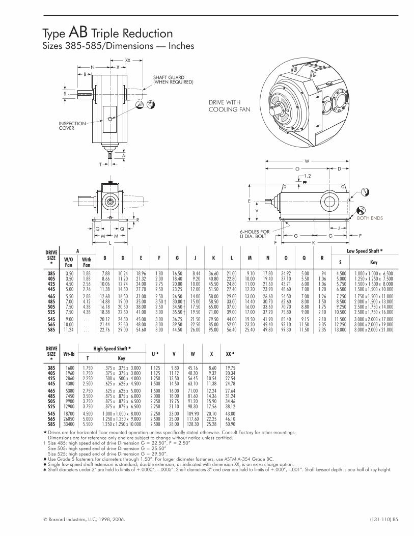
© Rexnord Industries, LLC, 1998, 2006. (131-110) 85
Type AB Triple ReductionSizes 385-585/Dimensions — Inches
DRIVESIZE
�
A
B D E F G J K L M N O Q R
Low Speed Shaft �
W/OFan
WithFan
S Key
385 3.50 1.88 7.88 10.24 18.96 1.80 16.50 8.44 36.60 21.00 9.10 17.80 34.92 5.00 .94 4.500 1.000 x 1.000 x 6.500405 3.50 1.88 8.66 11.20 21.32 2.00 18.40 9.20 40.80 22.80 10.00 19.40 37.10 5.50 1.06 5.000 1.250 x 1.250 x 7.500425 4.50 2.56 10.06 12.74 24.00 2.75 20.00 10.00 45.50 24.80 11.00 21.60 43.71 6.00 1.06 5.750 1.500 x 1.500 x 8.000445 5.00 2.76 11.38 14.50 27.70 2.50 23.25 12.00 51.50 27.40 12.20 23.90 48.60 7.00 1.20 6.500 1.500 x 1.500 x 10.000
465 5.50 2.88 12.68 16.50 31.00 2.50 26.50 14.00 58.00 29.00 13.00 26.60 54.50 7.00 1.26 7.250 1.750 x 1.500 x 11.000485 7.00 4.12 14.88 19.00 35.00 3.50 † 30.00 † 15.00 58.50 33.00 14.40 30.70 62.60 8.00 1.50 8.500 2.000 x 1.500 x 13.000505 7.50 4.38 16.18 20.50 38.00 2.50 34.50 † 17.50 65.00 37.00 16.00 33.60 70.70 8.80 1.75 9.250 2.500 x 1.750 x 14.000525 7.50 4.38 18.38 22.50 41.00 3.00 35.50 † 19.50 71.00 39.00 17.00 37.20 75.80 9.00 2.10 10.500 2.500 x 1.750 x 16.000
545 9.00 . . . 20.12 24.50 45.00 3.00 36.75 21.50 79.50 44.00 19.50 41.90 85.40 9.15 2.10 11.500 3.000 x 2.000 x 17.000565 10.00 . . . 21.44 25.50 48.00 3.00 39.50 22.50 85.00 52.00 23.20 45.40 92.10 11.50 2.35 12.250 3.000 x 2.000 x 19.000585 11.24 . . . 22.76 29.00 54.60 3.00 44.50 26.00 95.00 56.40 25.40 49.80 99.30 11.50 2.35 13.000 3.000 x 2.000 x 21.000
DRIVESIZE
�
Wt-lbHigh Speed Shaft �
U � V W X XX �T Key
385 1600 1.750 .375 x .375 x 3.000 1.125 9.80 45.16 8.60 19.75405 1960 1.750 .375 x .375 x 3.000 1.125 11.12 48.30 9.32 20.34425 2860 2.250 .500 x .500 x 4.000 1.250 12.50 56.45 10.54 22.54445 4380 2.500 .625 x .625 x 4.500 1.500 14.50 63.10 11.38 24.78
465 5380 2.750 .625 x .625 x 5.000 1.500 16.00 71.00 12.24 27.64485 7450 3.500 .875 x .875 x 6.000 2.000 18.00 81.60 14.36 31.24505 9900 3.750 .875 x .875 x 6.500 2.250 19.75 91.20 15.90 34.46525 12900 3.750 .875 x .875 x 6.500 2.250 21.10 98.30 17.56 38.12
545 18700 4.500 1.000 x 1.000 x 8.000 2.250 23.00 109.90 20.10 43.00565 26050 5.000 1.250 x 1.250 x 9.000 2.500 25.00 117.60 22.25 46.10585 33400 5.500 1.250 x 1.250 x 10.000 2.500 28.00 128.30 25.28 50.90
� Drives are for horizontal floor mounted operation unless specifically stated otherwise. Consult Factory for other mountings.Dimensions are for reference only and are subject to change without notice unless certified.
† Size 485: high speed end of drive Dimension G = 22.50”, F = 2.50”Size 505: high speed end of drive Dimension G = 25.50”Size 525: high speed end of drive Dimension G = 29.50”.
� Use Grade 5 fasteners for diameters through 1.50”. For larger diameter fasteners, use ASTM A-354 Grade BC.� Single low speed shaft extension is standard; double extension, as indicated with dimension XX, is an extra charge option.� Shaft diameters under 3” are held to limits of +.0000”, –.0005”. Shaft diameters 3” and over are held to limits of +.000”, –.001”. Shaft keyseat depth is one-half of key height.
W
O D
1.2
E
V
G
A
INSPECTIONCOVER
SHAFT GUARD(WHEN REQUIRED)
L
M M
B
N X
XX
T
F K
G F6-HOLES FORU DIA. BOLT
J
S
R BOTH ENDS
DRIVE WITHCOOLING FAN
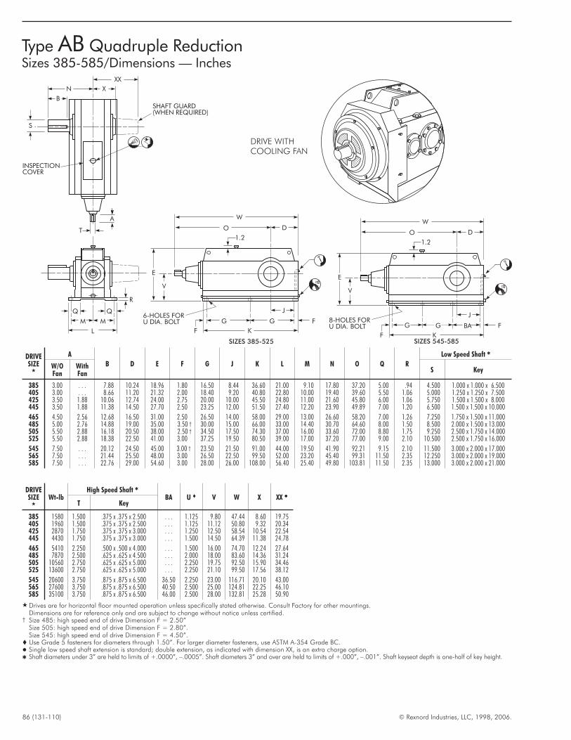
86 (131-110) © Rexnord Industries, LLC, 1998, 2006.
Type AB Quadruple ReductionSizes 385-585/Dimensions — Inches
DRIVESIZE
�
A
B D E F G J K L M N O Q R
Low Speed Shaft �
W/OFan
WithFan
S Key
385 3.00 . . . 7.88 10.24 18.96 1.80 16.50 8.44 36.60 21.00 9.10 17.80 37.20 5.00 .94 4.500 1.000 x 1.000 x 6.500405 3.00 . . . 8.66 11.20 21.32 2.00 18.40 9.20 40.80 22.80 10.00 19.40 39.60 5.50 1.06 5.000 1.250 x 1.250 x 7.500425 3.50 1.88 10.06 12.74 24.00 2.75 20.00 10.00 45.50 24.80 11.00 21.60 45.80 6.00 1.06 5.750 1.500 x 1.500 x 8.000445 3.50 1.88 11.38 14.50 27.70 2.50 23.25 12.00 51.50 27.40 12.20 23.90 49.89 7.00 1.20 6.500 1.500 x 1.500 x 10.000
465 4.50 2.56 12.68 16.50 31.00 2.50 26.50 14.00 58.00 29.00 13.00 26.60 58.20 7.00 1.26 7.250 1.750 x 1.500 x 11.000485 5.00 2.76 14.88 19.00 35.00 3.50 † 30.00 15.00 66.00 33.00 14.40 30.70 64.60 8.00 1.50 8.500 2.000 x 1.500 x 13.000505 5.50 2.88 16.18 20.50 38.00 2.50 † 34.50 17.50 74.30 37.00 16.00 33.60 72.00 8.80 1.75 9.250 2.500 x 1.750 x 14.000525 5.50 2.88 18.38 22.50 41.00 3.00 37.25 19.50 80.50 39.00 17.00 37.20 77.00 9.00 2.10 10.500 2.500 x 1.750 x 16.000
545 7.50 . . . 20.12 24.50 45.00 3.00 † 23.50 21.50 91.00 44.00 19.50 41.90 92.21 9.15 2.10 11.500 3.000 x 2.000 x 17.000565 7.50 . . . 21.44 25.50 48.00 3.00 26.50 22.50 99.50 52.00 23.20 45.40 99.31 11.50 2.35 12.250 3.000 x 2.000 x 19.000585 7.50 . . . 22.76 29.00 54.60 3.00 28.00 26.00 108.00 56.40 25.40 49.80 103.81 11.50 2.35 13.000 3.000 x 2.000 x 21.000
DRIVESIZE
�
Wt-lbHigh Speed Shaft �
BA U � V W X XX �T Key
385 1580 1.500 .375 x .375 x 2.500 . . . 1.125 9.80 47.44 8.60 19.75405 1960 1.500 .375 x .375 x 2.500 . . . 1.125 11.12 50.80 9.32 20.34425 2870 1.750 .375 x .375 x 3.000 . . . 1.250 12.50 58.54 10.54 22.54445 4430 1.750 .375 x .375 x 3.000 . . . 1.500 14.50 64.39 11.38 24.78
465 5410 2.250 .500 x .500 x 4.000 . . . 1.500 16.00 74.70 12.24 27.64485 7870 2.500 .625 x .625 x 4.500 . . . 2.000 18.00 83.60 14.36 31.24505 10560 2.750 .625 x .625 x 5.000 . . . 2.250 19.75 92.50 15.90 34.46525 13600 2.750 .625 x .625 x 5.000 . . . 2.250 21.10 99.50 17.56 38.12
545 20600 3.750 .875 x .875 x 6.500 36.50 2.250 23.00 116.71 20.10 43.00565 27600 3.750 .875 x .875 x 6.500 40.50 2.500 25.00 124.81 22.25 46.10585 35100 3.750 .875 x .875 x 6.500 46.00 2.500 28.00 132.81 25.28 50.90
� Drives are for horizontal floor mounted operation unless specifically stated otherwise. Consult Factory for other mountings.Dimensions are for reference only and are subject to change without notice unless certified.
† Size 485: high speed end of drive Dimension F = 2.50”Size 505: high speed end of drive Dimension F = 2.80”.Size 545: high speed end of drive Dimension F = 4.50”.
� Use Grade 5 fasteners for diameters through 1.50”. For larger diameter fasteners, use ASTM A-354 Grade BC.� Single low speed shaft extension is standard; double extension, as indicated with dimension XX, is an extra charge option.� Shaft diameters under 3” are held to limits of +.0000”, –.0005”. Shaft diameters 3” and over are held to limits of +.000”, –.001”. Shaft keyseat depth is one-half of key height.
A
B
N X
XX
T
S
INSPECTIONCOVER
SHAFT GUARD(WHEN REQUIRED)
L
M M
R
W
O D
1.2
E
V
G
F K
G F
J6-HOLES FORU DIA. BOLT
SIZES 385-525
W
O D
1.2
E
V
G
F K
BA F
J8-HOLES FORU DIA. BOLT
SIZES 545-585
G
DRIVE WITHCOOLING FAN
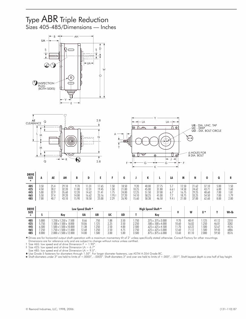
© Rexnord Industries, LLC, 1998, 2006. (131-110) 87
Type ABR Triple ReductionSizes 405-485/Dimensions — Inches
DRIVESIZE
�
A AE AH B D E F G J K L LA M N O Q R
405 3.50 25.4 29.10 9.70 11.31 17.65 1.50 18.50 9.20 40.00 27.75 5.7 12.50 21.62 37.10 5.00 1.50425 4.50 28.2 32.20 11.00 12.31 19.45 1.50 21.00 10.25 45.00 31.80 6.6 ‡ 14.50 24.62 43.71 6.00 1.60445 5.00 32.9 35.60 12.20 14.62 21.41 1.75 24.00 12.25 51.50 37.00 6.7 16.75 29.25 48.60 7.00 1.81465 5.50 37.4 39.20 14.00 16.62 23.16 1.95 † 27.20 14.10 58.25 41.00 7.7 18.75 33.25 54.50 7.00 1.79485 7.00 40.7 43.10 15.90 18.50 25.00 2.29 26.90 15.60 58.38 46.50 9.4 ‡ 21.00 37.00 62.60 8.00 2.00
DRIVESIZE
�
Low Speed Shaft � High Speed Shaft �
V W X � Y Wt-lbS Key UA UB UC UD T Key
405 5.000 1.250 x 1.250 x 7.500 8.66 .750 1.88 3.50 1.750 .375 x .375 x 3.000 9.70 48.41 1.125 41.12 2310425 5.750 1.500 x 1.500 x 8.000 10.06 1.125 2.25 3.50 2.250 .500 x .500 x 4.000 10.60 56.02 1.250 46.01 3282445 6.500 1.500 x 1.500 x 10.000 11.38 1.250 2.50 4.00 2.500 .625 x .625 x 4.500 11.70 63.22 1.500 52.67 4576465 7.250 1.750 x 1.500 x 11.000 12.68 1.250 2.50 4.75 2.750 .625 x .625 x 5.000 12.60 71.12 1.500 59.43 6806485 8.000 2.000 x 1.500 x 12.000 14.00 1.500 3.00 5.00 3.500 .875 x .875 x 6.000 13.60 81.10 2.000 59.50 8576
� Drives are for horizontal output shaft operation with a maximum momentary tilt of 2° unless specifically stated otherwise. Consult Factory for other mountings.Dimensions are for reference only and are subject to change without notice unless certified.
† Size 465: low speed end of drive Dimension F = 1.90”.‡ Size 425: low speed end of drive Dimension LA = 6.7”
Size 485: low speed end of drive Dimension LA = 9.5”.� Use Grade 5 fasteners for diameters through 1.50”. For larger diameter fasteners, use ASTM A-354 Grade BC.� Shaft diameters under 3” are held to limits of +.0000”, –.0005”. Shaft diameters 3” and over are held to limits of +.000”, –.001”. Shaft keyseat depth is one-half of key height.
K
Y
G G
J
FF
6-HOLES FORDIA. BOLTX
UBUCUD
- DIA. UNC. TAP- DEEP- DIA. BOLT CIRCLE
A
LA LA
M
NM
L
AECLEARANCE
Q
QR
2.8
2.8
E
O
W
D
AH
UA
B
V
S S
UA
T
INSPECTIONPLUG(BOTH SIDES)
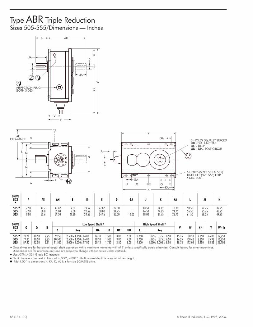
88 (131-110) © Rexnord Industries, LLC, 1998, 2006.
Type ABR Triple ReductionSizes 505-555/Dimensions — Inches
DRIVESIZE
�
A AE AH B D E G GA J K KA L M N
505 � 7.50 43.7 47.62 17.32 19.62 27.87 27.00 . . . 13.50 64.62 18.88 50.50 22.75 39.25535 7.50 50.8 52.00 19.50 22.62 30.00 31.75 . . . 16.50 74.25 21.75 56.50 25.75 45.25555 9.00 55.6 59.30 21.80 24.62 34.95 35.00 10.00 18.00 81.75 23.75 61.50 28.25 49.25
DRIVESIZE
�
O Q RLow Speed Shaft � High Speed Shaft �
V W X � Y Wt-lbS Key UA UB UC UD T Key
505 � 70.71 10.50 2.25 9.250 2.500 x 1.750 x 14.00 16.18 1.500 3.00 6.00 3.750 .875 x .875 x 6.50 15.16 90.33 2.250 65.83 12,250535 77.80 10.50 2.25 10.500 2.500 x 1.750 x 16.00 18.38 1.500 3.00 7.50 3.750 .875 x .875 x 6.50 16.25 100.42 2.250 75.92 16,650555 87.40 12.00 2.31 11.500 3.000 x 2.000 x 17.00 20.12 1.750 3.50 8.00 4.500 1.000 x 1.000 x 8.50 18.75 112.02 2.250 83.32 23,100
� Gear drives are for horizontal output shaft operation with a maximum momentary tilt of 2° unless specifically stated otherwise. Consult factory for other mountings.Dimensions are for reference only and are subject to change without notice unless certified.
� Use ASTM A-354 Grade BC fasteners.
� Shaft diameters are held to limits of +.000”, –.001”. Shaft keyseat depth is one-half of key height.� Add 1.00” to dimensions K, KA, D, W, & Y for size 505ABRJ drive.
Y
G
GA
G
K
J
6-HOLES (SIZES 505 & 535)10-HOLES (SIZE 555) FOR
DIA. BOLTX
N
R
Q
Q
M
ML
AECLEARANCE
UA
O
W
AHB
SUA
S
E
V
A
T
3-HOLES EQUALLY SPACED- DIA. UNC TAP- DEEP- DIA. BOLT CIRCLE
UBUCUD
D
KA
INSPECTION PLUG(BOTH SIDES)
GA
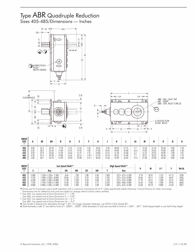
© Rexnord Industries, LLC, 1998, 2006. (131-110) 89
Type ABR Quadruple ReductionSizes 405-485/Dimensions — Inches
K
Y
G G
J
FF
6-HOLES FORDIA. BOLTX
UBUCUD
- DIA. UNC TAP- DEEP- DIA. BOLT CIRCLE
A
LA LA
M
NM
L
AECLEARANCE
Q
QR
2.8
2.8
E
O
W
D
AH
UA
B
V
S S
UA
T
INSPECTIONPLUG(BOTH SIDES)
DRIVESIZE
�
A AE AH B D E F G J K L LA M N O Q R
405 3.00 25.4 29.10 9.70 11.31 17.65 1.50 18.50 9.20 40.00 27.75 5.7 12.50 21.62 39.60 5.00 1.50425 3.50 28.2 32.20 11.00 12.31 19.45 1.50 21.00 10.25 45.00 31.80 6.6 ‡ 14.50 24.62 45.80 6.00 1.60445 3.50 32.9 35.60 12.20 14.62 21.41 1.75 24.00 12.25 51.50 37.00 6.7 16.75 29.25 49.89 7.00 1.81465 4.50 37.4 39.20 14.00 16.62 23.16 1.95 † 27.20 14.10 58.25 41.00 7.7 18.75 33.25 58.20 7.00 1.79485 5.00 40.7 43.10 15.90 18.50 25.00 2.41 † 30.60 15.60 56.90 46.50 9.4 ‡ 21.00 37.00 64.60 8.00 2.00
DRIVESIZE
�
Low Speed Shaft � High Speed Shaft �
V W X � Y Wt-lbS Key UA UB UC UD T Key
405 5.000 1.250 x 1.250 x 7.500 8.66 .750 1.88 3.50 1.500 .375 x .375 x 2.500 9.70 50.91 1.125 41.12 2458425 5.750 1.500 x 1.500 x 8.000 10.06 1.125 2.25 3.50 1.750 .375 x .375 x 3.000 10.60 58.11 1.250 46.01 3286445 6.500 1.500 x 1.500 x 10.000 11.38 1.250 2.50 4.00 1.750 .375 x .375 x 3.000 11.70 64.51 1.500 52.67 4543465 7.250 1.750 x 1.500 x 11.000 12.68 1.250 2.50 4.75 2.250 .500 x .500 x 4.000 12.60 74.82 1.500 59.43 6863485 8.000 2.000 x 1.500 x 12.000 14.00 1.500 3.00 5.00 2.500 .625 x .625 x 4.500 13.60 83.10 2.000 67.04 9057
� Drives are for horizontal output shaft operation with a maximum momentary tilt of 2° unless specifically stated otherwise. Consult Factory for other mountings.Dimensions are for reference only and are subject to change without notice unless certified.
† Size 465: low speed end of drive Dimension F = 1.90”Size 485: low speed end of drive Dimension F = 2.29”.
‡ Size 425: low speed end of drive Dimension LA = 6.7”Size 485: low speed end of drive Dimension LA = 9.5”.
� Use Grade 5 fasteners for diameters through 1.50”. For larger diameter fasteners, use ASTM A-354 Grade BC.� Shaft diameters under 3” are held to limits of +.0000”, –.0005”. Shaft diameters 3” and over are held to limits of +.000”, –.001”. Shaft keyseat depth is one-half of key height.
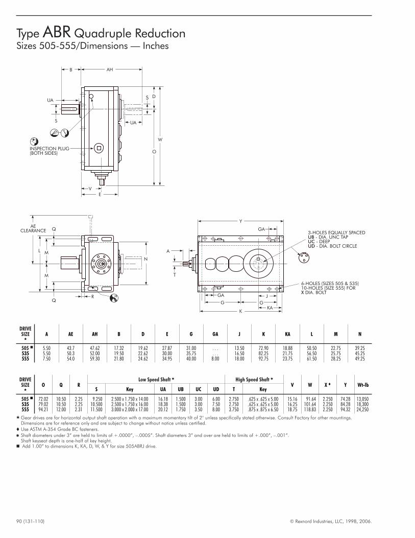
90 (131-110) © Rexnord Industries, LLC, 1998, 2006.
DRIVESIZE
�
A AE AH B D E G GA J K KA L M N
505 � 5.50 43.7 47.62 17.32 19.62 27.87 31.00 . . . 13.50 72.90 18.88 50.50 22.75 39.25535 5.50 50.3 52.00 19.50 22.62 30.00 35.75 . . . 16.50 82.25 21.75 56.50 25.75 45.25555 7.50 54.0 59.30 21.80 24.62 34.95 40.00 8.00 18.00 92.75 23.75 61.50 28.25 49.25
DRIVESIZE
�
O Q RLow Speed Shaft � High Speed Shaft �
V W X � Y Wt-lbS Key UA UB UC UD T Key
505 � 72.02 10.50 2.25 9.250 2.500 x 1.750 x 14.00 16.18 1.500 3.00 6.00 2.750 .625 x .625 x 5.00 15.16 91.64 2.250 74.28 13,050535 79.02 10.50 2.25 10.500 2.500 x 1.750 x 16.00 18.38 1.500 3.00 7.50 2.750 .625 x .625 x 5.00 16.25 101.64 2.250 84.28 18,300555 94.21 12.00 2.31 11.500 3.000 x 2.000 x 17.00 20.12 1.750 3.50 8.00 3.750 .875 x .875 x 6.50 18.75 118.83 2.250 94.32 24,250
� Gear drives are for horizontal output shaft operation with a maximum momentary tilt of 2° unless specifically stated otherwise. Consult Factory for other mountings.Dimensions are for reference only and are subject to change without notice unless certified.
� Use ASTM A-354 Grade BC fasteners.
� Shaft diameters under 3” are held to limits of +.0000”, –.0005”. Shaft diameters 3” and over are held to limits of +.000”, –.001”.Shaft keyseat depth is one-half of key height.� Add 1.00” to dimensions K, KA, D, W, & Y for size 505ABRJ drive.
Y
G
GA
G
K
J
6-HOLES (SIZES 505 & 535)10-HOLES (SIZE 555) FOR
DIA. BOLTX
N
R
Q
Q
M
ML
AECLEARANCE
D
O
W
AHB
UA
S
KA
UA
S
EV
A
T
3-HOLES EQUALLY SPACED- DIA. UNC TAP- DEEP- DIA. BOLT CIRCLE
UBUCUD
GA
INSPECTION PLUG(BOTH SIDES)
Type ABR Quadruple ReductionSizes 505-555/Dimensions — Inches
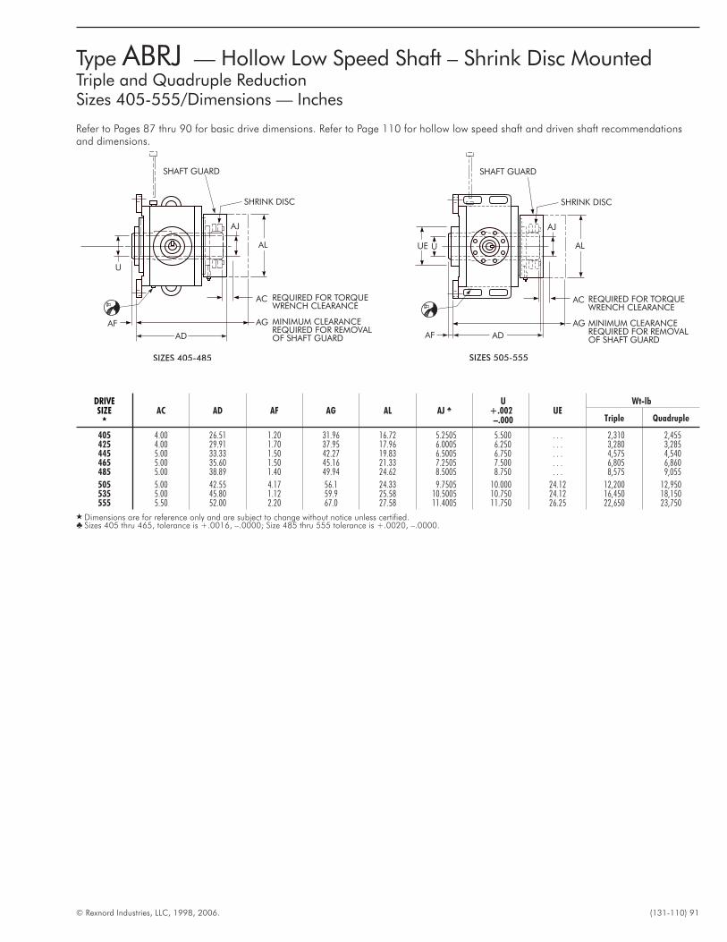
© Rexnord Industries, LLC, 1998, 2006. (131-110) 91
Type ABRJ — Hollow Low Speed Shaft – Shrink Disc MountedTriple and Quadruple ReductionSizes 405-555/Dimensions — Inches
Refer to Pages 87 thru 90 for basic drive dimensions. Refer to Page 110 for hollow low speed shaft and driven shaft recommendationsand dimensions.
AD
ALUE
AG
AC
SHAFT GUARD
SHRINK DISC
U
AJ
MINIMUM CLEARANCEREQUIRED FOR REMOVALOF SHAFT GUARD
REQUIRED FOR TORQUEWRENCH CLEARANCE
AF
SIZES 505-555
DRIVESIZE
�
AC AD AF AG AL AJ �
U+.002–.000
UEWt-lb
Triple Quadruple
405 4.00 26.51 1.20 31.96 16.72 5.2505 5.500 . . . 2,310 2,455425 4.00 29.91 1.70 37.95 17.96 6.0005 6.250 . . . 3,280 3,285445 5.00 33.33 1.50 42.27 19.83 6.5005 6.750 . . . 4,575 4,540465 5.00 35.60 1.50 45.16 21.33 7.2505 7.500 . . . 6,805 6,860485 5.00 38.89 1.40 49.94 24.62 8.5005 8.750 . . . 8,575 9,055
505 5.00 42.55 4.17 56.1 24.33 9.7505 10.000 24.12 12,200 12,950535 5.00 45.80 1.12 59.9 25.58 10.5005 10.750 24.12 16,450 18,150555 5.50 52.00 2.20 67.0 27.58 11.4005 11.750 26.25 22,650 23,750
� Dimensions are for reference only and are subject to change without notice unless certified.� Sizes 405 thru 465, tolerance is +.0016, –.0000; Size 485 thru 555 tolerance is +.0020, –.0000.
AL
AF AG
AC
SHAFT GUARD
SHRINK DISC
U
AJ
MINIMUM CLEARANCEREQUIRED FOR REMOVALOF SHAFT GUARD
REQUIRED FOR TORQUEWRENCH CLEARANCE
AD
SIZES 405-485
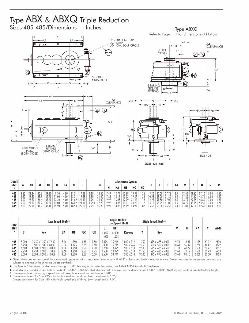
92 (131-110) © Rexnord Industries, LLC, 1998, 2006.
Type ABX & ABXQ Triple ReductionSizes 405-485/Dimensions — Inches
K
G G FF
J
Y
6-HOLESDIA. BOLTX
UBUCUD
- DIA. UNC TAP- DEEP- DIA. BOLT CIRCLE
LA LA
W H
DO
AH
B
E
V
UA
T
INSPECTIONPLUG
(BOTH SIDES)
GREASEFITTING
(ABXD ONLY)
UA
A
AECLEARANCE
S
S
N
HB
MM
L
Q Q
HD
HCHC
R
2.82.8
HA
SIZES 425-485
SIZE 405
HA
HC
HD
HB
DRIVESIZE
�
A AD AE AH B BA D E F GLubrication System
J K L LA M N O Q RH HA HB HC HD
405 3.50 21.34 30.6 29.10 9.70 4.50 11.31 17.65 1.50 18.50 7.47 12.71 10.88 19.99 1.25 9.20 40.00 27.75 5.7 12.50 21.62 37.10 5.00 1.50425 4.50 23.50 33.5 32.20 11.00 4.00 12.31 19.45 1.50 21.00 7.65 13.19 10.03 19.57 1.35 10.25 45.00 31.80 6.6 ‡ 14.50 24.62 43.71 6.00 1.60445 5.00 25.50 36.4 35.60 12.20 4.60 14.62 21.41 1.75 24.00 9.92 16.88 12.09 21.42 1.18 12.25 51.50 37.00 6.7 16.75 29.25 48.60 7.00 1.81465 5.50 27.23 39.2 39.20 14.00 4.60 16.62 23.16 1.95 † 27.20 9.92 18.88 13.34 23.20 1.42 14.10 58.25 41.00 7.7 18.75 33.25 54.50 7.00 1.79485 7.00 29.18 41.9 43.10 15.90 5.40 18.50 25.00 2.29 26.90 9.92 18.88 15.09 24.97 1.87 15.60 58.38 46.50 9.4 ‡ 21.00 37.00 62.60 8.00 2.00
DRIVESIZE
�
Low Speed Shaft � Keyed HollowLow Speed Shaft
High Speed Shaft �
V W X � Y Wt-lb
S Key UA UB UC UD
U
+.002–.000
UE
+.000–.005
Keyway T Key
405 5.000 1.250 x 1.250 x 7.500 8.66 .750 1.88 3.50 5.375 15.249 1.000 x .312 1.750 .375 x .375 x 3.000 9.70 48.41 1.125 41.12 2410425 5.750 1.500 x 1.500 x 8.000 10.06 1.125 2.25 3.50 6.000 15.749 1.500 x .265 2.250 .500 x .500 x 4.000 10.60 56.02 1.250 46.01 3379445 6.500 1.500 x 1.500 x 10.000 11.38 1.250 2.50 4.00 6.750 18.499 1.500 x .510 2.500 .625 x .625 x 4.500 11.70 63.22 1.500 52.67 4697465 7.250 1.750 x 1.500 x 11.000 12.68 1.250 2.50 4.75 7.500 20.999 1.500 x .510 2.750 .625 x .625 x 5.000 12.60 71.12 1.500 59.43 6933485 8.000 2.000 x 1.500 x 12.000 14.00 1.500 3.00 5.00 8.500 23.749 1.500 x .510 3.500 .875 x .875 x 6.000 13.60 81.10 2.000 59.50 8703
� Gear drives are for horizontal floor mounted operation with a maximum momentary tilt of 2° unless specifically stated otherwise. Dimensions are for reference only and aresubject to change without notice unless certified.
� Use Grade 5 fasteners for diameters through 1.50”. For larger diameter fasteners, use ASTM A-354 Grade BC fasteners.
� Shaft diameters under 3” are held to limits of +.0000”, –.0005”. Shaft diameters 3” and over are held to limits of +.000”, –.001”. Shaft keyseat depth is one-half of key height.† Dimension shown is for high speed end of drive. Low speed end of drive is 1.90”.‡ Dimension shown for Size 425 is for high speed end of drive. Low speed end is 6.7”;
Dimension shown for Size 485 is for high speed end of drive. Low speed end is 9.5”.
HD
BEARINGGREASEFITTING
AE
CLEARANCE
SHAFTCOVER
AD
UEBAU
Type ABXQRefer to Page 111 for dimensions of Hollow
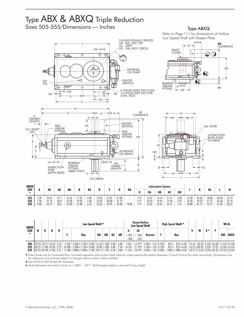
© Rexnord Industries, LLC, 1998, 2006. (131-110) 93
Type ABX & ABXQ Triple ReductionSizes 505-555/Dimensions — Inches
DRIVESIZE
�
A AD AE AH B BA D E G GALubrication System
J K KA L MH HA HB HC HD
505 7.50 33.06 47.1 47.62 17.32 6.80 19.62 27.87 27.00 . . . 9.91 16.82 16.34 27.67 2.80 13.50 64.62 18.88 50.50 22.75535 7.50 35.18 50.8 52.00 19.50 6.80 22.62 30.00 31.75 . . . 9.91 20.00 18.84 29.68 3.05 16.50 74.25 21.75 56.50 25.75555 9.00 40.39 58.5 59.30 21.80 6.60 24.62 34.95 35.00 10.00 9.91 20.00 20.84 34.51 3.41 18.00 81.75 23.75 61.50 28.25
DRIVESIZE
�
N O Q R
Low Speed Shaft � Keyed HollowLow Speed Shaft
High Speed Shaft �
V W X � Y
Wt-lb
S Key UA UB UC UD
U
+.002–.000
UE
+.000–.005
Keyway T Key ABX ABXQ
505 39.25 70.71 10.50 2.25 9.250 2.500 x 1.750 x 14.00 16.18 1.500 3.00 6.00 9.001 24.999 2.000 x .510 3.750 .875 x .875 x 6.50 15.16 90.33 2.250 65.83 12,450 12,500535 45.25 77.80 10.50 2.25 10.500 2.500 x 1.750 x 16.00 18.38 1.500 3.00 7.50 10.501 27.999 2.500 x .760 3.750 .875 x .875 x 6.50 16.25 100.42 2.250 75.92 16,500 16,650555 49.25 87.40 12.00 2.31 11.500 3.000 x 2.000 x 17.00 20.12 1.750 3.50 8.00 11.502 28.999 3.000 x .760 4.500 1.000 x 1.000 x 8.50 18.75 112.02 2.250 83.32 23,500 23,050
� Gear drives are for horizontal floor mounted operation only (output shaft vertical) unless specifically stated otherwise. Consult Factory for other mountings. Dimensions arefor reference only and are subject to change without notice unless certified.
� Use ASTM A-354 Grade BC fasteners.
� Shaft diameters are held to limits of +.000”, –.001”. Shaft keyseat depth is one-half of key height.
HD
UA
UAUSABLELENGTH
B
VENTEDDIPSTICK
SEALGREASEFITTING
ALTERNATEOIL DRAIN
AH
BEARINGGREASEFITTING(ABXD ONLY)
OIL DRAIN
S
D
S
H
EXTERNALOIL PUMP
Y
G
GA
GFA FB
K
J6-HOLES (SIZES 505 & 535)10-HOLES (SIZE 555) FORX DIA. BOLT
KA
OILFILL
VENTEDDIPSTICK
AECLEARANCE
LA LB
W
O
E
V T
SEALGREASEFITTING
AUSEABLELENGTH
H.S. SHAFTKEY
LIFTING EYESBOTH ENDSOF DRIVE
OIL FILTER
N
HA HB
HC
R
MM
L
3-HOLES EQUALLY SPACEDUB - DIA. UNC TAPUC - DEEPUD - DIA. BOLT CIRCLEGA
INSPECTIONPORT(BOTH SIDES)
HD
BEARINGGREASEFITTING
AE
CLEARANCE
SHAFTCOVER
AD
UEBAU
Type ABXQRefer to Page 111 for dimensions of HollowLow Speed Shaft with Keeper Plate.
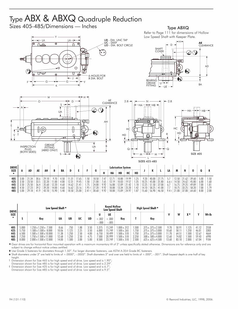
94 (131-110) © Rexnord Industries, LLC, 1998, 2006.
Type ABX & ABXQ Quadruple ReductionSizes 405-485/Dimensions — Inches
K
G G FF
J
Y
6-HOLES FORDIA. BOLTX
UBUCUD
- DIA. UNC TAP- DEEP- DIA. BOLT CIRCLE
LA LA
W H
DO
AH
N
HB
MM
L
B
E
V
UA
T
INSPECTIONPLUG
(BOTH SIDES)
GREASEFITTING
(ABXD ONLY)
A
AECLEARANCE
SIZES 425-485
S
S
Q Q
HD
HC
R
2.82.8
HA
SIZE 405
HA
HC
HD
HB
UA
DRIVESIZE
�
A AD AE AH B BA D E F GLubrication System
J K L LA M N O Q RH HA HB HC HD
405 3.00 21.34 30.6 29.10 9.70 4.50 11.31 17.65 1.50 18.50 7.47 12.71 10.88 19.99 1.25 9.20 40.00 27.75 5.7 12.50 21.62 39.60 5.00 1.50425 3.50 23.50 33.5 32.20 11.00 4.00 12.31 19.45 1.50 21.00 7.65 13.19 10.03 19.57 1.35 10.25 45.00 31.80 6.6 ‡ 14.50 24.62 45.80 6.00 1.60445 3.50 25.50 36.4 35.60 12.20 4.60 14.62 21.41 1.75 24.00 9.92 16.88 12.09 21.42 1.18 12.25 51.50 37.00 6.7 16.75 29.25 49.89 7.00 1.81465 4.50 27.23 39.2 39.20 14.00 4.60 16.62 23.16 1.95 † 27.20 9.92 18.88 13.34 23.20 1.42 14.10 58.25 41.00 7.7 18.75 33.25 58.20 7.00 1.79485 5.00 29.18 41.9 43.10 15.90 5.40 18.50 25.00 2.41 † 30.60 9.92 18.88 15.09 24.97 1.87 15.60 56.90 46.50 9.4 ‡ 21.00 37.00 64.60 8.00 2.00
DRIVESIZE
�
Low Speed Shaft � Keyed HollowLow Speed Shaft
High Speed Shaft �
V W X � Y Wt-lb
S Key UA UB UC UD
U
+.002–.000
UE
+.000–.005
Key T Key
405 5.000 1.250 x 1.250 x 7.500 8.66 .750 1.88 3.50 5.375 15.249 1.000 x .312 1.500 .375 x .375 x 2.500 9.70 50.91 1.125 41.12 2558425 5.750 1.500 x 1.500 x 8.000 10.06 1.125 2.25 3.50 6.000 15.749 1.500 x .265 1.750 .375 x .375 x 3.000 10.60 58.11 1.250 46.01 3383445 6.500 1.500 x 1.500 x 10.000 11.38 1.250 2.50 4.00 6.750 18.499 1.500 x .510 1.750 .375 x .375 x 3.000 11.70 64.51 1.500 52.67 4664465 7.250 1.750 x 1.500 x 11.000 12.68 1.250 2.50 4.75 7.500 20.999 1.500 x .510 2.250 .500 x .500 x 4.000 12.60 74.82 1.500 59.43 6990485 8.000 2.000 x 1.500 x 12.000 14.00 1.500 3.00 5.00 8.500 23.749 1.500 x .510 2.500 .625 x .625 x 4.500 13.60 83.10 2.000 67.04 9184
� Gear drives are for horizontal floor mounted operation with a maximum momentary tilt of 2° unless specifically stated otherwise. Dimensions are for reference only and aresubject to change without notice unless certified.
� Use Grade 5 fasteners for diameters through 1.50”. For larger diameter fasteners, use ASTM A-354 Grade BC fasteners.
� Shaft diameters under 3” are held to limits of +.0000”, –.0005”. Shaft diameters 3” and over are held to limits of +.000”, –.001”. Shaft keyseat depth is one-half of keyheight.
† Dimension shown for Size 465 is for high speed end of drive. Low speed end is 1.90”;Dimension shown for Size 485 is for high speed end of drive. Low speed end is 2.29”.
‡ Dimension shown for Size 425 is for high speed end of drive. Low speed end is 6.7”;Dimension shown for Size 485 is for high speed end of drive. Low speed end is 9.5”.
HD
BEARINGGREASEFITTING
AE
CLEARANCE
SHAFTCOVER
AD
UEBAU
Type ABXQRefer to Page 111 for dimensions of HollowLow Speed Shaft with Keeper Plate.
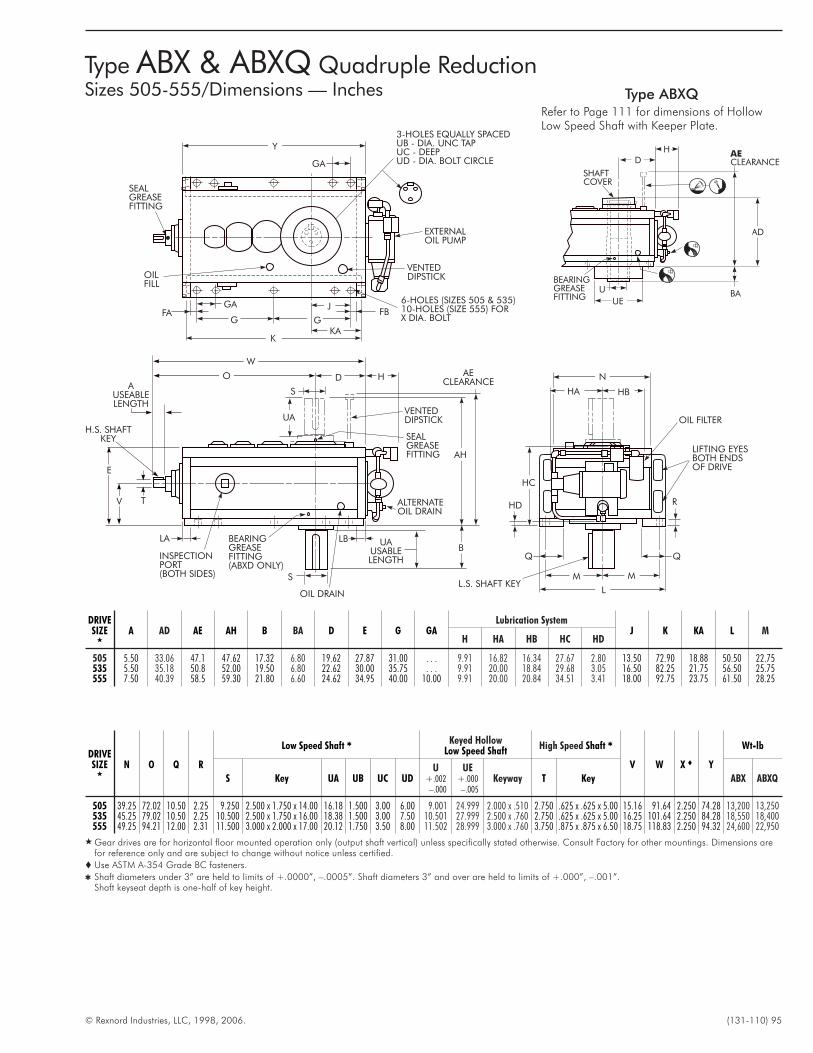
© Rexnord Industries, LLC, 1998, 2006. (131-110) 95
Type ABX & ABXQ Quadruple ReductionSizes 505-555/Dimensions — Inches
DRIVESIZE
�
A AD AE AH B BA D E G GALubrication System
J K KA L MH HA HB HC HD
505 5.50 33.06 47.1 47.62 17.32 6.80 19.62 27.87 31.00 . . . 9.91 16.82 16.34 27.67 2.80 13.50 72.90 18.88 50.50 22.75535 5.50 35.18 50.8 52.00 19.50 6.80 22.62 30.00 35.75 . . . 9.91 20.00 18.84 29.68 3.05 16.50 82.25 21.75 56.50 25.75555 7.50 40.39 58.5 59.30 21.80 6.60 24.62 34.95 40.00 10.00 9.91 20.00 20.84 34.51 3.41 18.00 92.75 23.75 61.50 28.25
DRIVESIZE
�
N O Q R
Low Speed Shaft � Keyed HollowLow Speed Shaft
High Speed Shaft �
V W X � Y
Wt-lb
S Key UA UB UC UDU
+.002–.000
UE+.000–.005
Keyway T Key ABX ABXQ
505 39.25 72.02 10.50 2.25 9.250 2.500 x 1.750 x 14.00 16.18 1.500 3.00 6.00 9.001 24.999 2.000 x .510 2.750 .625 x .625 x 5.00 15.16 91.64 2.250 74.28 13,200 13,250535 45.25 79.02 10.50 2.25 10.500 2.500 x 1.750 x 16.00 18.38 1.500 3.00 7.50 10.501 27.999 2.500 x .760 2.750 .625 x .625 x 5.00 16.25 101.64 2.250 84.28 18,550 18,400555 49.25 94.21 12.00 2.31 11.500 3.000 x 2.000 x 17.00 20.12 1.750 3.50 8.00 11.502 28.999 3.000 x .760 3.750 .875 x .875 x 6.50 18.75 118.83 2.250 94.32 24,600 22,950
� Gear drives are for horizontal floor mounted operation only (output shaft vertical) unless specifically stated otherwise. Consult Factory for other mountings. Dimensions arefor reference only and are subject to change without notice unless certified.
� Use ASTM A-354 Grade BC fasteners.
� Shaft diameters under 3” are held to limits of +.0000”, –.0005”. Shaft diameters 3” and over are held to limits of +.000”, –.001”.Shaft keyseat depth is one-half of key height.
LIFTING EYESBOTH ENDSOF DRIVE
OIL FILTER
N
HA HB
HC
HD R
MM
LL.S. SHAFT KEY
UA
UAUSABLELENGTH
B
VENTEDDIPSTICK
SEALGREASEFITTING
ALTERNATEOIL DRAIN
AH
BEARINGGREASEFITTING(ABXD ONLY)
SEALGREASEFITTING
OIL DRAIN
S
D
S
H
EXTERNALOIL PUMP
Y
G
GA
GFA FB
K
J6-HOLES (SIZES 505 & 535)10-HOLES (SIZE 555) FORX DIA. BOLT
KA
OILFILL
VENTEDDIPSTICK
AECLEARANCE
LA LB
W
O
E
V T
AUSEABLELENGTH
H.S. SHAFTKEY
3-HOLES EQUALLY SPACEDUB - DIA. UNC TAPUC - DEEPUD - DIA. BOLT CIRCLEGA
INSPECTIONPORT(BOTH SIDES)
HD
BEARINGGREASEFITTING
AE
CLEARANCE
SHAFTCOVER
AD
UEBAU
Type ABXQRefer to Page 111 for dimensions of HollowLow Speed Shaft with Keeper Plate.
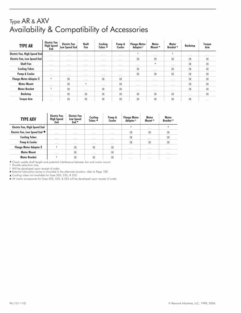
96 (131-110) © Rexnord Industries, LLC, 1998, 2006.
Type AR & AXVAvailability & Compatibility of Accessories
TYPE ARElectric FanHigh Speed
End
Electric FanLow Speed End
ShaftFan
CoolingTubes �
Pump &Cooler
Flange MotorAdapter ‡
MotorMount �
MotorBracket � Backstop
TorqueArm
Electric Fan, High Speed End . . . . . . . . . . . . . . . † . . . † . . . . . .
Electric Fan, Low Speed End . . . . . . . . . . . . . . . OK OK OK OK OK
Shaft Fan . . . . . . . . . . . . . . . . . . � . . . OK OK
Cooling Tubes . . . . . . . . . . . . . . . OK . . . OK OK OK
Pump & Cooler . . . . . . . . . . . . . . . OK OK OK OK OK
Flange Motor Adapter ‡ † OK . . . OK OK . . . . . . . . . OK OK
Motor Mount . . . OK � . . . OK . . . . . . . . . OK OK
Motor Bracket † OK . . . OK OK . . . . . . . . . OK OK
Backstop . . . OK OK OK OK OK OK OK . . . OK
Torque Arm . . . OK OK OK OK OK OK OK OK . . .
TYPE AXVElectric FanHigh Speed
End
Electric FanLow Speed
End �CoolingTubes �
Pump &Cooler
Flange MotorAdapter ‡
MotorMount �
MotorBracket �
Electric Fan, High Speed End . . . . . . . . . . . . † . . . †
Electric Fan, Low Speed End � . . . . . . . . . . . . OK OK OK
Cooling Tubes . . . . . . . . . . . . OK . . . OK
Pump & Cooler . . . . . . . . . . . . OK OK OK
Flange Motor Adapter ‡ † OK OK OK . . . . . . . . .
Motor Mount . . . OK . . . OK . . . . . . . . .
Motor Bracket † OK OK OK . . . . . . . . .
� Check usable shaft length and potential interference between fan and motor mount.† Double reduction only.‡ Will be developed upon receipt of order.� External lubrication pump is mounted in the alternate location, refer to Page 108.
� Cooling tubes not available for Sizes 505, 535, & 555.
� All motor accessories for Sizes 505, 535, & 555 will be developed upon receipt of order.
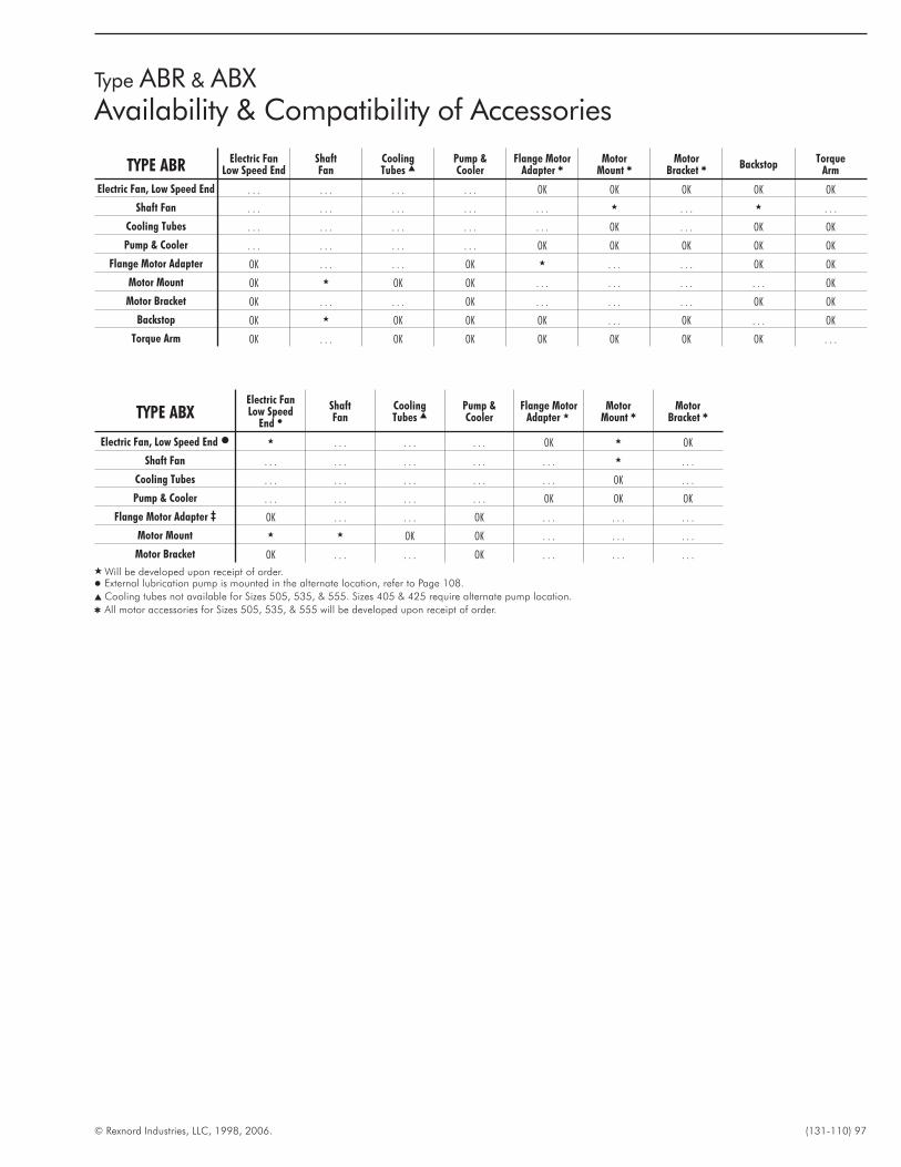
© Rexnord Industries, LLC, 1998, 2006. (131-110) 97
Type ABR & ABXAvailability & Compatibility of Accessories
TYPE ABRElectric Fan
Low Speed EndShaftFan
CoolingTubes �
Pump &Cooler
Flange MotorAdapter �
MotorMount �
MotorBracket � Backstop
TorqueArm
Electric Fan, Low Speed End . . . . . . . . . . . . OK OK OK OK OK
Shaft Fan . . . . . . . . . . . . . . . � . . . � . . .
Cooling Tubes . . . . . . . . . . . . . . . OK . . . OK OK
Pump & Cooler . . . . . . . . . . . . OK OK OK OK OK
Flange Motor Adapter OK . . . . . . OK � . . . . . . OK OK
Motor Mount OK � OK OK . . . . . . . . . . . . OK
Motor Bracket OK . . . . . . OK . . . . . . . . . OK OK
Backstop OK � OK OK OK . . . OK . . . OK
Torque Arm OK . . . OK OK OK OK OK OK . . .
TYPE ABXElectric FanLow Speed
End �ShaftFan
CoolingTubes �
Pump &Cooler
Flange MotorAdapter �
MotorMount �
MotorBracket �
Electric Fan, Low Speed End � � . . . . . . . . . OK � OK
Shaft Fan . . . . . . . . . . . . . . . � . . .
Cooling Tubes . . . . . . . . . . . . . . . OK . . .
Pump & Cooler . . . . . . . . . . . . OK OK OK
Flange Motor Adapter ‡ OK . . . . . . OK . . . . . . . . .
Motor Mount � � OK OK . . . . . . . . .
Motor Bracket OK . . . . . . OK . . . . . . . . .
� Will be developed upon receipt of order.� External lubrication pump is mounted in the alternate location, refer to Page 108.
� Cooling tubes not available for Sizes 505, 535, & 555. Sizes 405 & 425 require alternate pump location.
� All motor accessories for Sizes 505, 535, & 555 will be developed upon receipt of order.
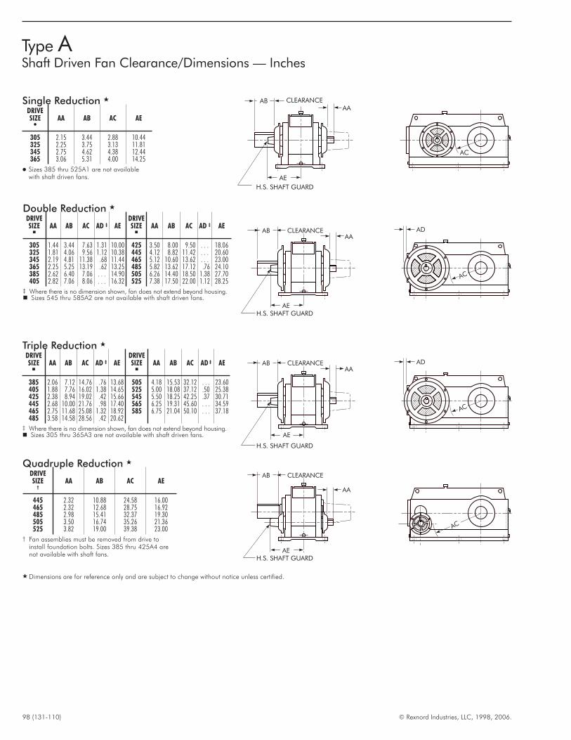
98 (131-110) © Rexnord Industries, LLC, 1998, 2006.
Type AShaft Driven Fan Clearance/Dimensions — Inches
CLEARANCEAB
AEH.S. SHAFT GUARD
AA
AC
CLEARANCEAB
AE
H.S. SHAFT GUARD
AA
AC
AD
CLEARANCEAB
AEH.S. SHAFT GUARD
AA
AC
AD
Single Reduction �
DRIVESIZE�
AA AB AC AE
305 2.15 3.44 2.88 10.44325 2.25 3.75 3.13 11.81345 2.75 4.62 4.38 12.44365 3.06 5.31 4.00 14.25
� Sizes 385 thru 525A1 are not availablewith shaft driven fans.
Double Reduction �
DRIVESIZE�
AA AB AC AD ‡ AEDRIVESIZE�
AA AB AC AD ‡ AE
305 1.44 3.44 7.63 1.31 10.00 425 3.50 8.00 9.50 . . . 18.06325 1.81 4.06 9.56 1.12 10.38 445 4.12 8.82 11.42 . . . 20.60345 2.19 4.81 11.38 .68 11.44 465 5.12 10.60 13.62 . . . 23.00365 2.25 5.25 13.19 .62 13.25 485 5.82 13.62 17.12 .76 24.10385 2.62 6.40 7.06 . . . 14.90 505 6.26 14.40 18.50 1.38 27.70405 2.82 7.06 8.06 . . . 16.32 525 7.38 17.50 22.00 1.12 28.25
‡ Where there is no dimension shown, fan does not extend beyond housing.� Sizes 545 thru 585A2 are not available with shaft driven fans.
Triple Reduction �
DRIVESIZE�
AA AB AC AD ‡ AEDRIVESIZE�
AA AB AC AD ‡ AE
385 2.06 7.12 14.76 .76 13.68 505 4.18 15.53 32.12 . . . 23.60405 1.88 7.76 16.02 1.38 14.65 525 5.00 18.08 37.12 .50 25.38425 2.38 8.94 19.02 .42 15.66 545 5.50 18.25 42.25 .37 30.71445 2.68 10.00 21.76 .98 17.40 565 6.25 19.31 45.60 . . . 34.59465 2.75 11.68 25.08 1.32 18.92 585 6.75 21.04 50.10 . . . 37.18485 3.58 14.58 28.56 .42 20.62
‡ Where there is no dimension shown, fan does not extend beyond housing.� Sizes 305 thru 365A3 are not available with shaft driven fans.
Quadruple Reduction �
DRIVESIZE
†AA AB AC AE
445 2.32 10.88 24.58 16.00465 2.32 12.68 28.75 16.92485 2.98 15.41 32.37 19.30505 3.50 16.74 35.26 21.36525 3.82 19.00 39.38 23.00
† Fan assemblies must be removed from drive toinstall foundation bolts. Sizes 385 thru 425A4 arenot available with shaft fans.
AC
CLEARANCEAB
AE
H.S. SHAFT GUARD
AA
� Dimensions are for reference only and are subject to change without notice unless certified.
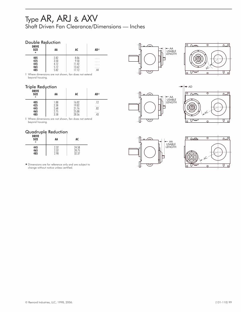
© Rexnord Industries, LLC, 1998, 2006. (131-110) 99
Type AR, ARJ & AXVShaft Driven Fan Clearance/Dimensions — Inches
AC
AC
AC
AAUSABLELENGTH
AAUSABLELENGTH
AAUSABLELENGTH
AD
Double ReductionDRIVESIZE
�
AA AC AD ‡
405 2.82 8.06 . . . .425 3.50 9.50 . . . .445 4.12 11.42 . . . .465 5.12 13.62 . . . .485 5.82 17.12 .44
‡ Where dimensions are not shown, fan does not extendbeyond housing.
Triple ReductionDRIVESIZE
�
AA AC AD ‡
405 1.88 16.02 .12425 2.38 19.02 . . . .445 2.68 21.76 .02465 2.75 25.08 . . . .485 3.58 28.56 .43
‡ Where dimensions are not shown, fan does not extendbeyond housing.
Quadruple ReductionDRIVESIZE
�
AA AC
445 2.32 24.58465 2.32 28.75485 2.98 32.37
� Dimensions are for reference only and are subject tochange without notice unless certified.
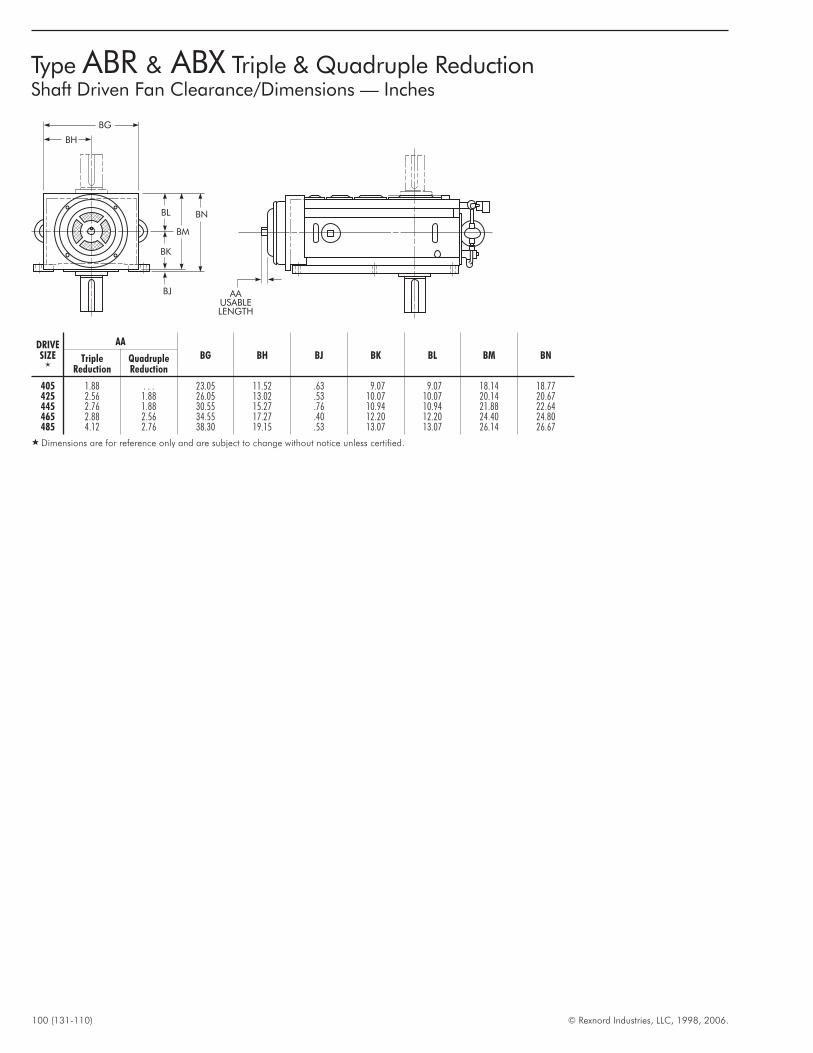
100 (131-110) © Rexnord Industries, LLC, 1998, 2006.
Type ABR & ABX Triple & Quadruple ReductionShaft Driven Fan Clearance/Dimensions — Inches
BG
BH
BL
BK
BJ
BM
BN
AAUSABLELENGTH
DRIVESIZE
�
AA
BG BH BJ BK BL BM BNTripleReduction
QuadrupleReduction
405 1.88 . . . 23.05 11.52 .63 9.07 9.07 18.14 18.77425 2.56 1.88 26.05 13.02 .53 10.07 10.07 20.14 20.67445 2.76 1.88 30.55 15.27 .76 10.94 10.94 21.88 22.64465 2.88 2.56 34.55 17.27 .40 12.20 12.20 24.40 24.80485 4.12 2.76 38.30 19.15 .53 13.07 13.07 26.14 26.67
� Dimensions are for reference only and are subject to change without notice unless certified.
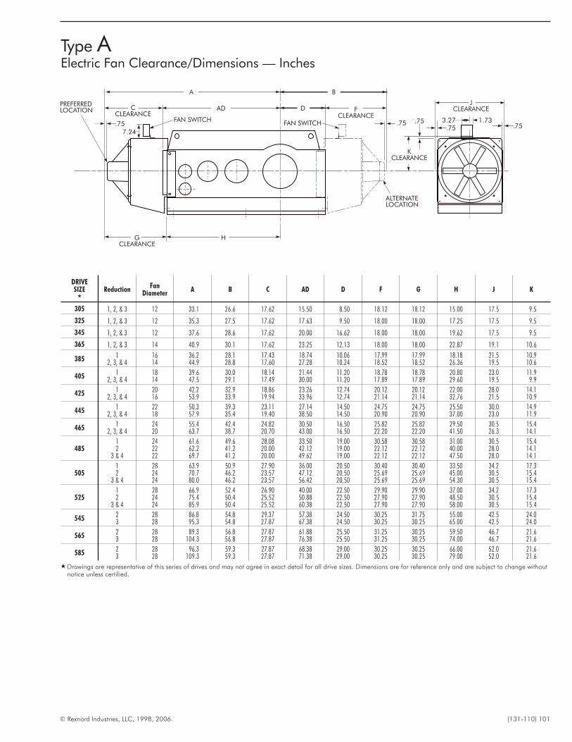
© Rexnord Industries, LLC, 1998, 2006. (131-110) 101
DRIVESIZE
�
ReductionFan
DiameterA B C AD D F G H J K
305 1, 2, & 3 12 33.1 26.6 17.62 15.50 8.50 18.12 18.12 15.00 17.5 9.5
325 1, 2, & 3 12 35.3 27.5 17.62 17.63 9.50 18.00 18.00 17.25 17.5 9.5
345 1, 2, & 3 12 37.6 28.6 17.62 20.00 16.62 18.00 18.00 19.62 17.5 9.5
365 1, 2, & 3 14 40.9 30.1 17.62 23.25 12.13 18.00 18.00 22.87 19.1 10.6
385 1 16 36.2 28.1 17.43 18.74 10.06 17.99 17.99 18.18 21.5 10.92, 3, & 4 14 44.9 28.8 17.60 27.28 10.24 18.52 18.52 26.36 19.5 10.6
405 1 18 39.6 30.0 18.14 21.44 11.20 18.78 18.78 20.80 23.0 11.92, 3, & 4 14 47.5 29.1 17.49 30.00 11.20 17.89 17.89 29.60 19.5 9.9
425 1 20 42.2 32.9 18.86 23.26 12.74 20.12 20.12 22.00 28.0 14.12, 3, & 4 16 53.9 33.9 19.94 33.96 12.74 21.14 21.14 32.76 21.5 10.9
445 1 22 50.3 39.3 23.11 27.14 14.50 24.75 24.75 25.50 30.0 14.92, 3, & 4 18 57.9 35.4 19.40 38.50 14.50 20.90 20.90 37.00 23.0 11.9
465 1 24 55.4 42.4 24.82 30.50 16.50 25.82 25.82 29.50 30.5 15.42, 3, & 4 20 63.7 38.7 20.70 43.00 16.50 22.20 22.20 41.50 26.3 14.1
4851 24 61.6 49.6 28.08 33.50 19.00 30.58 30.58 31.00 30.5 15.42 22 62.2 41.2 20.00 42.12 19.00 22.12 22.12 40.00 28.0 14.1
3 & 4 22 69.7 41.2 20.00 49.62 19.00 22.12 22.12 47.50 28.0 14.1
5051 28 63.9 50.9 27.90 36.00 20.50 30.40 30.40 33.50 34.2 17.32 24 70.7 46.2 23.57 47.12 20.50 25.69 25.69 45.00 30.5 15.4
3 & 4 24 80.0 46.2 23.57 56.42 20.50 25.69 25.69 54.30 30.5 15.4
5251 28 66.9 52.4 26.90 40.00 22.50 29.90 29.90 37.00 34.2 17.32 24 75.4 50.4 25.52 50.88 22.50 27.90 27.90 48.50 30.5 15.4
3 & 4 24 85.9 50.4 25.52 60.38 22.50 27.90 27.90 58.00 30.5 15.4
545 2 28 86.8 54.8 29.37 57.38 24.50 30.25 31.75 55.00 42.5 24.03 28 95.3 54.8 27.87 67.38 24.50 30.25 30.25 65.00 42.5 24.0
565 2 28 89.3 56.8 27.87 61.88 25.50 31.25 30.25 59.50 46.7 21.63 28 104.3 56.8 27.87 76.38 25.50 31.25 30.25 74.00 46.7 21.6
585 2 28 96.3 59.3 27.87 68.38 29.00 30.25 30.25 66.00 52.0 21.63 28 109.3 59.3 27.87 71.38 29.00 30.25 30.25 79.00 52.0 21.6
� Drawings are representative of this series of drives and may not agree in exact detail for all drive sizes. Dimensions are for reference only and are subject to change withoutnotice unless certified.
.75 .75.75.75
A
AD D
B
H
ALTERNATELOCATION
JCLEARANCE
KCLEARANCE
CCLEARANCE
GCLEARANCE
FCLEARANCE
PREFERREDLOCATION
.75
7.24
FAN SWITCHFAN SWITCH 1.733.27
Type AElectric Fan Clearance/Dimensions — Inches
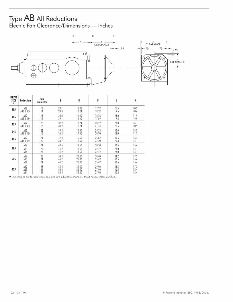
102 (131-110) © Rexnord Industries, LLC, 1998, 2006.
Type AB All ReductionsElectric Fan Clearance/Dimensions — Inches
JCLEARANCE
B
FCLEARANCE
.75
D
.75 .75.75
KCLEARANCE
DRIVESIZE
�
ReductionFan
DiameterB D F J K
385 AB2 16 28.1 10.06 17.99 21.5 10.9AB3 & AB4 14 28.8 10.24 18.52 19.5 10.6
405 AB2 18 30.0 11.20 18.78 23.0 11.9AB3 & AB4 14 29.1 11.20 17.89 19.5 9.9
425 AB2 20 32.9 12.74 20.12 28.0 14.1AB3 & AB4 16 33.9 12.74 21.14 21.5 10.9
445 AB2 22 39.3 14.50 24.75 30.0 14.9AB3 & AB4 18 35.4 14.50 20.90 23.0 11.9
465 AB2 24 42.4 16.50 25.82 30.5 15.4AB3 & AB4 20 38.7 16.50 22.20 26.3 14.1
485AB2 24 49.6 18.50 30.58 30.5 15.4AB3 22 41.2 18.50 22.12 28.0 14.1AB4 22 41.2 18.50 22.12 28.0 14.1
505AB2 28 50.9 20.00 30.40 34.2 17.3AB3 24 46.2 20.00 25.69 30.5 15.4AB4 24 46.2 20.00 25.69 30.5 15.4
525AB2 28 52.4 22.50 29.90 34.2 17.3AB3 24 50.4 22.50 27.90 30.5 15.4AB4 24 50.4 22.50 27.90 30.5 15.4
� Dimensions are for reference only and are subject to change without notice unless certified.
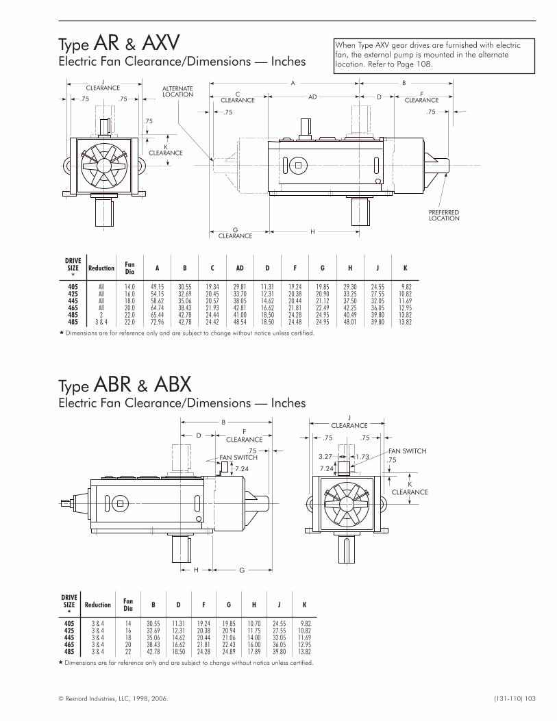
© Rexnord Industries, LLC, 1998, 2006. (131-110) 103
Type AR & AXVElectric Fan Clearance/Dimensions — Inches
JCLEARANCE
.75 .75
.75
KCLEARANCE
B
FCLEARANCE
D
GH
.751.733.27
7.247.24
FAN SWITCHFAN SWITCH
DRIVESIZE
�
ReductionFanDia
B D F G H J K
405 3 & 4 14 30.55 11.31 19.24 19.85 10.70 24.55 9.82425 3 & 4 16 32.69 12.31 20.38 20.94 11.75 27.55 10.82445 3 & 4 18 35.06 14.62 20.44 21.06 14.00 32.05 11.69465 3 & 4 20 38.43 16.62 21.81 22.43 16.00 36.05 12.95485 3 & 4 22 42.78 18.50 24.28 24.89 17.89 39.80 13.82
� Dimensions are for reference only and are subject to change without notice unless certified.
DRIVESIZE
�
ReductionFanDia
A B C AD D F G H J K
405 All 14.0 49.15 30.55 19.34 29.81 11.31 19.24 19.85 29.30 24.55 9.82425 All 16.0 54.15 32.69 20.45 33.70 12.31 20.38 20.90 33.25 27.55 10.82445 All 18.0 58.62 35.06 20.57 38.05 14.62 20.44 21.12 37.50 32.05 11.69465 All 20.0 64.74 38.43 21.93 42.81 16.62 21.81 22.49 42.25 36.05 12.95485 2 22.0 65.44 42.78 24.44 41.00 18.50 24.28 24.95 40.49 39.80 13.82485 3 & 4 22.0 72.96 42.78 24.42 48.54 18.50 24.48 24.95 48.01 39.80 13.82
� Dimensions are for reference only and are subject to change without notice unless certified.
.75
.75
KCLEARANCE
JCLEARANCE
.75
A
CCLEARANCE
AD D FCLEARANCE
B
.75
PREFERREDLOCATION
HGCLEARANCE
ALTERNATELOCATION
.75
When Type AXV gear drives are furnished with electricfan, the external pump is mounted in the alternatelocation. Refer to Page 108.
Type ABR & ABXElectric Fan Clearance/Dimensions — Inches
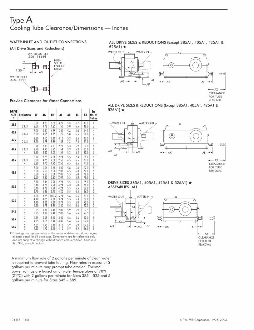
104 (131-110) © The Falk Corporation, 1998, 2003.
Type ACooling Tube Clearance/Dimensions — Inches
AG AK AL
AX
CLEARANCEFOR TUBEREMOVAL
AH
WATER IN
AJ
WATER OUT
AF
1.25.60
WATER INLET.500-14 NPT
WATER OUTLET.500 - 14 NPT
HIGHSPEEDEND OFDRIVE
WATER INLET AND OUTLET CONNECTIONS
(All Drive Sizes and Reductions)
Provide Clearance for Water Connections
DRIVESIZE
�
Reduction AF AG AH AJ AK AL AXStd
No. ofTubes
385 1 3.00 4.20 6.50 4.20 5.3 6.7 41.0 42 & 3 2.50 3.76 4.25 1.50 5.8 5.5 48.0 2
405 1 3.00 5.40 6.75 5.40 5.3 6.0 44.0 42 & 3 3.00 4.05 4.75 1.79 5.8 6.5 54.0 2
425 1 2.50 4.10 7.15 4.10 5.3 6.5 47.0 62 & 3 2.20 4.75 5.55 1.59 7.3 7.3 61.0 4
4451 3.20 7.30 7.71 2.78 5.3 5.9 52.0 6
2 & 3 2.70 4.90 5.95 1.54 5.3 5.3 63.0 44 3.30 3.80 5.05 1.54 5.3 5.3 63.0 2
4651 3.20 7.25 7.68 2.74 5.5 7.3 59.0 6
2 & 3 3.00 4.75 7.00 2.50 6.5 6.5 71.0 44 3.20 4.75 4.95 2.50 6.5 6.5 71.0 2
485
1 3.20 6.56 9.48 4.30 5.8 6.3 62.0 82 3.50 6.60 8.00 2.08 6.5 6.3 72.0 63 3.50 6.60 8.00 2.08 5.5 5.8 78.0 64 3.50 4.30 5.25 2.04 5.5 5.8 78.0 2
505
1 3.70 7.46 9.98 2.94 5.5 5.4 65.0 82 3.40 8.76 7.90 4.24 6.3 6.0 78.0 63 3.40 8.76 7.90 4.24 5.5 5.5 86.0 64 3.70 6.46 5.45 4.20 5.5 5.5 86.0 2
525
1 4.00 8.25 10.35 6.74 5.6 5.6 71.0 82 4.10 8.25 7.60 3.74 5.5 5.3 82.0 63 4.10 8.25 7.60 3.74 5.5 5.8 92.0 64 4.10 5.75 5.85 3.50 5.5 5.8 92.0 2
545 2 3.85 9.81 7.40 2.00 5.9 5.9 87.5 83 3.85 9.81 7.40 2.00 5.6 5.6 97.5 8
565 2 4.85 10.65 8.40 3.40 5.6 5.6 93.0 83 4.85 10.65 8.40 3.40 5.6 5.6 107.0 8
585 2 4.85 11.90 8.40 4.10 5.9 5.9 104.0 83 4.85 11.90 8.40 4.10 5.9 5.9 116.0 8
� Drawings are representative of this series of drives and do not agreein exact detail for all drive sizes. Dimensions are for reference onlyand are subject to change without notice unless certified. Sizes 305thru 365, consult Factory.
A minimum flow rate of 2 gallons per minute of clean wateris required to prevent tube fouling. Flow rates in excess of 5gallons per minute may prompt tube erosion. Thermalpower ratings are based on a water temperature of 70ºF(21ºC) with 2 gallons per minute for Sizes 385 – 525 and 5gallons per minute for Sizes 545 – 585.
ALL DRIVE SIZES & REDUCTIONS (Except 385A1, 405A1, 425A1 &525A1) �
AG AK AL
AX
CLEARANCEFOR TUBEREMOVAL
AH
WATER OUT
AJ
WATER IN
AF
ALL DRIVE SIZES & REDUCTIONS (Except 385A1, 405A1, 425A1 &525A1) �
AG AK AL
AX
CLEARANCEFOR TUBEREMOVAL
AH
WATER IN
AJ
WATER OUT
AF
DRIVE SIZES 385A1, 405A1, 425A1 & 525A1) �
ASSEMBLIES: ALL
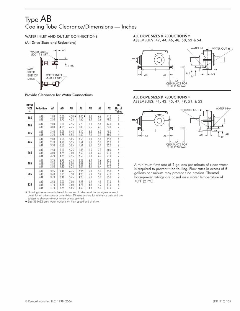
© Rexnord Industries, LLC, 1998, 2006. (131-110) 105
Type ABCooling Tube Clearance/Dimensions — Inches
1.25
.60
WATER INLET.500-14 NPT
WATER OUTLET.500 - 14 NPT
LOWSPEEDEND OFDRIVE
WATER INLET AND OUTLET CONNECTIONS
(All Drive Sizes and Reductions)
Provide Clearance for Water Connections
DRIVESIZE
�
Reduction AF AG AH AJ AK AL AXStd
No. ofTubes
385 AB2 1.88 0.00 4.38 � 4.40 � 5.8 6.6 41.0 3AB3 2.50 3.75 4.25 1.50 5.4 5.6 48.0 2
405 AB2 2.00 0.00 4.95 5.70 6.1 5.6 44.0 4AB3 3.00 4.05 4.75 1.80 5.5 6.3 53.0 2
425 AB2 2.40 2.05 5.45 6.10 6.5 6.3 48.0 4AB3 2.20 4.75 5.55 1.60 7.1 7.1 60.0 4
445AB2 2.80 7.50 5.85 0.50 6.8 5.8 63.0 6AB3 2.70 4.90 5.95 1.54 5.1 5.1 62.0 4AB4 3.30 3.80 5.05 1.54 5.1 5.1 62.0 2
465AB2 2.50 7.60 5.75 1.85 6.5 7.1 60.0 6AB3 3.00 4.75 7.00 2.50 6.3 6.3 71.0 4AB4 3.20 4.75 4.95 2.50 6.3 6.3 71.0 2
485AB2 3.25 6.75 6.75 2.25 6.4 5.6 62.0 6AB3 3.50 6.60 8.00 2.08 6.1 5.9 71.0 6AB4 3.50 4.30 5.25 2.04 5.1 5.4 77.0 2
505AB2 3.25 7.46 6.75 2.96 5.9 5.1 65.0 6AB3 3.40 8.75 7.90 4.25 5.9 5.6 77.0 6AB4 3.70 6.46 5.45 4.20 5.1 5.1 85.0 2
525AB2 3.50 9.00 7.00 2.25 6.2 4.9 71.0 8AB3 4.10 8.25 7.60 3.75 4.9 4.7 81.0 6AB4 4.10 5.75 5.85 3.50 4.9 5.1 91.0 2
� Drawings are representative of this series of drives and do not agree in exactdetail for all drive sizes or assemblies. Dimensions are for reference only and aresubject to change without notice unless certified.
� Size 385AB2 only, water outlet is on high speed end of drive.
A minimum flow rate of 2 gallons per minute of clean wateris required to prevent tube fouling. Flow rates in excess of 5gallons per minute may prompt tube erosion. Thermalhorsepower ratings are based on a water temperature of70ºF (21ºC).
ALL DRIVE SIZES & REDUCTIONS �
ASSEMBLIES: 42, 44, 46, 48, 50, 52 & 54
ALAK
AXCLEARANCE FORTUBE REMOVAL
AGAF
AH
AJ
WATER INWATER OUT �
ALAK
AXCLEARANCE FORTUBE REMOVAL
AGAF
AH
AJ
WATER IN WATER OUT �
ALL DRIVE SIZES & REDUCTIONS �
ASSEMBLIES: 41, 43, 45, 47, 49, 51, & 53
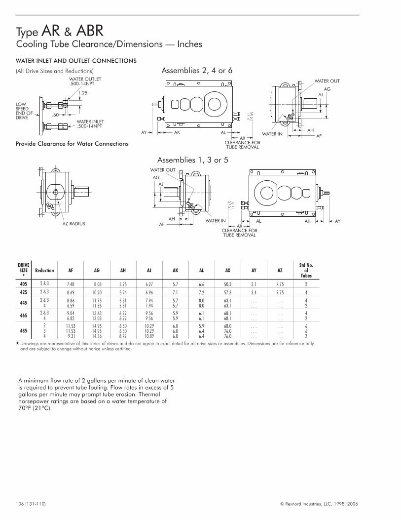
106 (131-110) © Rexnord Industries, LLC, 1998, 2006.
Type AR & ABRCooling Tube Clearance/Dimensions — Inches
AK AY
AFWATER INAH
AJAG
WATER OUT
Assemblies 2, 4 or 6
Assemblies 1, 3 or 5
AK AL
AL
AY
AXCLEARANCE FORTUBE REMOVAL
AXCLEARANCE FORTUBE REMOVAL
AHAF
WATER IN
AG
1.25
.60
LOWSPEEDEND OFDRIVE
WATER OUTLET.500-14NPT
WATER INLET.500-14NPT
AJ
WATER OUT
AZ RADIUS
DRIVESIZE
�
Reduction AF AG AH AJ AK AL AX AY AZStd No.
ofTubes
405 2 & 3 7.48 8.08 5.25 6.27 5.7 6.6 50.3 2.1 7.75 2
425 2 & 3 8.69 10.20 5.24 6.96 7.1 7.2 57.3 3.4 7.75 4
4452 & 3 8.86 11.75 5.81 7.94 5.7 8.0 63.1 . . . . . . 4
4 6.59 11.35 5.81 7.94 5.7 8.0 63.1 . . . . . . 2
4652 & 3 9.04 13.63 6.22 9.56 5.9 6.1 68.1 . . . . . . 4
4 6.82 13.03 6.22 9.56 5.9 6.1 68.1 . . . . . . 2
4852 11.53 14.95 6.50 10.29 6.0 5.9 68.0 . . . . . . 63 11.53 14.95 6.50 10.29 6.0 6.4 76.0 . . . . . . 64 9.31 14.36 8.72 10.89 6.0 6.4 76.0 . . . . . . 2
� Drawings are representative of this series of drives and do not agree in exact detail for all drive sizes or assemblies. Dimensions are for reference onlyand are subject to change without notice unless certified.
Provide Clearance for Water Connections
WATER INLET AND OUTLET CONNECTIONS
(All Drive Sizes and Reductions)
A minimum flow rate of 2 gallons per minute of clean wateris required to prevent tube fouling. Flow rates in excess of 5gallons per minute may prompt tube erosion. Thermalhorsepower ratings are based on a water temperature of70ºF (21ºC).
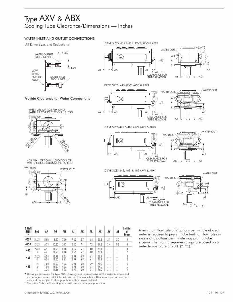
© Rexnord Industries, LLC, 1998, 2006. (131-110) 107
Type AXV & ABXCooling Tube Clearance/Dimensions — Inches
1.25
.60
WATER INLET.500-14 NPT
WATER OUTLET.500 - 14 NPT
LOWSPEEDEND OFDRIVE
SIZE
405
AZRA
DIU
S SIZE425
AZ
RAD
IUS
THIS TUBE ON 405 ABX ONLY(WITH INLET & OUTLET ON L.S. END)
405 ABX - OPTIONAL LOCATION OFWATER CONNECTIONS ON H.S. END
WATER INWATER OUT
AH
AG
AF
AJ
7.4RAD
IUS
AXCLEARANCE FORTUBE REMOVAL
AH
WATER OUTWATER OUT
AGAJ
AFALAKAY
AXCLEARANCE FORTUBE REMOVAL
AH
WATER OUT
AGAJ
AFALAKAY
AXCLEARANCE FORTUBE REMOVAL
ALAK
WATER IN
AF
WATER OUT
AJAG
AH
AXCLEARANCE FORTUBE REMOVAL
ALAK
WATER IN
AH
WATER OUT
AJAG
AF
DRIVE SIZES 465 & 485 AXV2 AXV3 & ABX3
DRIVE SIZES 445 AXV2, AXV3 & ABX3
DRIVE SIZES 405 & 425 AXV2, AXV3 & ABX3
DRIVE SIZES 445, 465 & 485 AXV4 & ABX4
DRIVESIZE
�
Red AF AG AH AJ AK AL AX AY AZStd No.
ofTubes
405 † 2 & 3 5.50 8.50 7.00 7.60 5.7 6.6 50.3 2.1 3.7 2
425 † 2 & 3 5.33 10.20 7.73 10.20 7.1 7.2 57.3 3.4 8.5 4
445 2 & 3 6.31 11.50 8.88 11.19 5.7 8.0 63.1 . . . . . . 44 6.31 11.50 8.88 9.62 5.7 8.0 63.1 . . . . . . 2
465 2 & 3 6.54 12.99 8.95 12.99 5.9 6.1 68.1 . . . . . . 44 6.54 11.00 8.95 12.99 5.9 6.1 68.1 . . . . . . 2
4852 7.00 13.50 9.76 15.94 6.0 5.9 68.0 . . . . . . 63 7.00 13.50 9.76 15.94 6.0 6.4 76.0 . . . . . . 64 6.75 14.46 9.76 12.99 6.0 6.4 76.0 . . . . . . 2
� Drawings shown are for Type ABX. Drawings are representative of this series of drives anddo not agree in exact detail for all drive sizes or assemblies. Dimensions are for referenceonly and are subject to change without notice unless certified.
† Sizes 405 & 425 with cooling tubes will use alternate pump location.
WATER INLET AND OUTLET CONNECTIONS
(All Drive Sizes and Reductions)
Provide Clearance for Water Connections
A minimum flow rate of 2 gallons per minute of cleanwater is required to prevent tube fouling. Flow rates inexcess of 5 gallons per minute may prompt tubeerosion. Thermal horsepower ratings are based on awater temperature of 70ºF (21ºC).
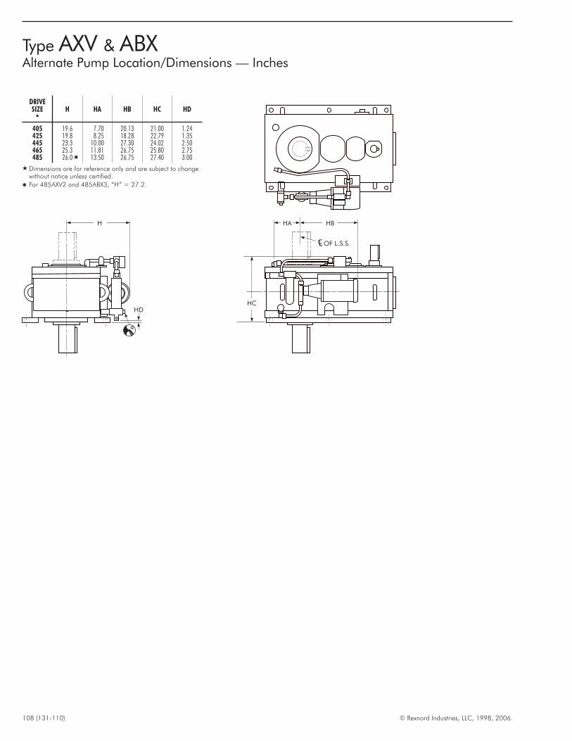
108 (131-110) © Rexnord Industries, LLC, 1998, 2006.
DRIVESIZE
�
H HA HB HC HD
405 19.6 7.70 20.13 21.00 1.24425 19.8 8.25 18.28 22.79 1.35445 23.3 10.00 27.30 24.02 2.50465 25.3 11.81 26.75 25.80 2.75485 26.0 � 13.50 26.75 27.40 3.00
� Dimensions are for reference only and are subject to changewithout notice unless certified.
� For 485AXV2 and 485ABX3, “H” = 27.2.
H HA HB
OF L.S.S.LC
HCHD
Type AXV & ABXAlternate Pump Location/Dimensions — Inches
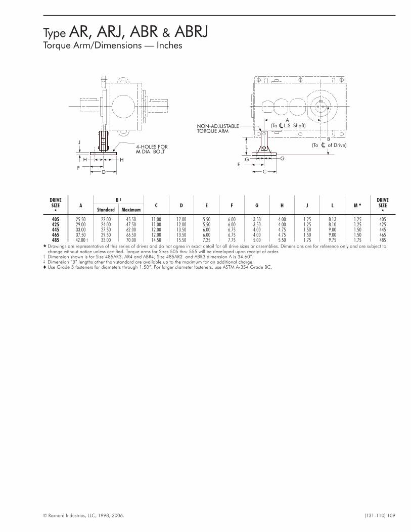
© Rexnord Industries, LLC, 1998, 2006. (131-110) 109
Type AR, ARJ, ABR & ABRJTorque Arm/Dimensions — Inches
GE
G
C
NON-ADJUSTABLETORQUE ARM
F
H
D
H
J4-HOLES FOR
DIA. BOLTM
(To C of Drive)LL
(To C L.S. Shaft)LA
B
DRIVESIZE
�
AB ‡
C D E F G H J L M �
DRIVESIZE
�Standard Maximum
405 25.50 22.00 45.50 11.00 12.00 5.50 6.00 3.50 4.00 1.25 8.13 1.25 405425 29.00 24.00 47.50 11.00 12.00 5.50 6.00 3.50 4.00 1.25 8.10 1.25 425445 33.00 27.50 62.00 12.00 13.50 6.00 6.75 4.00 4.75 1.50 9.00 1.50 445465 37.50 29.50 66.50 12.00 13.50 6.00 6.75 4.00 4.75 1.50 9.00 1.50 465485 42.00 † 33.00 70.00 14.50 15.50 7.25 7.75 5.00 5.50 1.75 9.75 1.75 485
� Drawings are representative of this series of drives and do not agree in exact detail for all drive sizes or assemblies. Dimensions are for reference only and are subject tochange without notice unless certified. Torque arms for Sizes 505 thru 555 will be developed upon receipt of order.
† Dimension shown is for Size 485AR3, AR4 and ABR4; Size 485AR2 and ABR3 dimension A is 34.60”.‡ Dimension ”B” lengths other than standard are available up to the maximum for an additional charge.� Use Grade 5 fasteners for diameters through 1.50”. For larger diameter fasteners, use ASTM A-354 Grade BC.
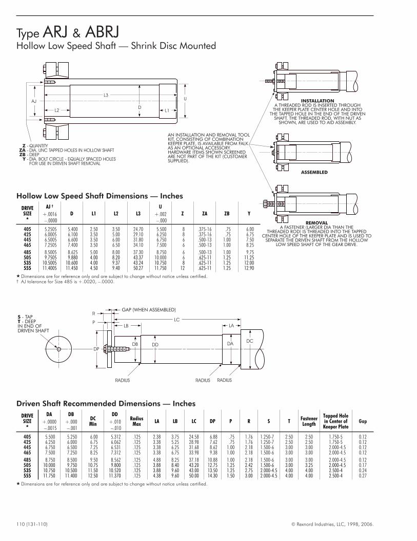
110 (131-110) © Rexnord Industries, LLC, 1998, 2006.
Type ARJ & ABRJHollow Low Speed Shaft — Shrink Disc Mounted
Driven Shaft Recommended Dimensions — Inches
DRIVESIZE
�
DA
+.0000–.0015
DB
+.000–.001
DCMin
DD
+.010–.010
RadiusMax
LA LB LC DP P R S TFastenerLength
Tapped Holein Center ofKeeper Plate
Gap
405 5.500 5.250 6.00 5.312 .125 2.38 3.75 24.58 6.88 .75 1.76 1.250-7 2.50 2.50 1.750-5 0.12425 6.250 6.000 6.75 6.062 .125 3.38 5.25 28.98 7.62 .75 1.76 1.250-7 2.50 2.50 1.750-5 0.12445 6.750 6.500 7.25 6.531 .125 3.38 6.25 31.68 8.62 1.00 2.18 1.500-6 3.00 3.00 2.000-4.5 0.12465 7.500 7.250 8.25 7.312 .125 3.38 6.75 33.98 9.38 1.00 2.18 1.500-6 3.00 3.00 2.000-4.5 0.12
485 8.750 8.500 9.50 8.562 .125 4.88 8.25 37.18 10.88 1.00 2.18 1.500-6 3.00 3.00 2.000-4.5 0.12505 10.000 9.750 10.75 9.800 .125 3.88 8.40 43.20 12.75 1.25 2.42 1.500-6 3.00 3.25 2.000-4.5 0.17535 10.750 10.500 11.50 10.520 .125 3.88 9.60 43.00 13.50 1.25 2.75 2.000-4.5 4.00 4.00 2.500-4 0.24555 11.750 11.400 12.50 11.370 .125 4.38 9.60 50.00 14.30 1.50 3.00 2.000-4.5 4.00 4.00 2.500-4 0.27
� Dimensions are for reference only and are subject to change without notice unless certified.
Hollow Low Speed Shaft Dimensions — Inches
DRIVESIZE
�
AJ †
+.0016–.0000
D L1 L2 L3
U
+.002–.000
Z ZA ZB Y
405 5.2505 5.400 2.50 3.50 24.70 5.500 8 .375-16 .75 6.00425 6.0005 6.100 3.50 5.00 29.10 6.250 8 .375-16 .75 6.75445 6.5005 6.600 3.50 6.00 31.80 6.750 6 .500-13 1.00 7.50465 7.2505 7.400 3.50 6.50 34.10 7.500 6 .500-13 1.00 8.25
485 8.5005 8.625 5.00 8.00 37.30 8.750 6 .500-13 1.00 9.75505 9.7505 9.880 4.00 8.20 43.37 10.000 6 .625-11 1.25 11.25535 10.5005 10.600 4.00 9.37 43.24 10.750 8 .625-11 1.25 12.00555 11.4005 11.450 4.50 9.40 50.27 11.750 12 .625-11 1.25 12.90
� Dimensions are for reference only and are subject to change without notice unless certified.† AJ tolerance for Size 485 is +.0020, –.0000.
L2
AJ
D
U
L1
L3
QUANTITY
DIA. UNC TAPPED HOLES IN HOLLOW SHAFT
DEEP
DIA. BOLT CIRCLE - EQUALLY SPACED HOLES
FOR USE IN DRIVEN SHAFT REMOVAL
Z
ZA
ZB
Y
----
P
RGAP (WHEN ASSEMBLED)
LB
DDDB
DP
LC
LA
DADC
RADIUSRADIUS RADIUS
S
T
- TAP- DEEP
IN END OFDRIVEN SHAFT
ASSEMBLED
REMOVAL
A FASTENER (LARGER DIA THAN THETHREADED ROD) IS THREADED INTO THE TAPPED
CENTER HOLE OF THE KEEPER PLATE AND IS USED TOSEPARATE THE DRIVEN SHAFT FROM THE HOLLOW
LOW SPEED SHAFT OF THE GEAR DRIVE.
AN INSTALLATION AND REMOVAL TOOLKIT, CONSISTING OF COMBINATIONKEEPER PLATE, IS AVAILABLE FROM FALKAS AN OPTIONAL ACCESSORY.HARDWARE ITEMS SHOWN SCREENEDARE NOT PART OF THE KIT (CUSTOMERSUPPLIED).
INSTALLATION
A THREADED ROD IS INSERTED THROUGHTHE KEEPER PLATE CENTER HOLE AND INTO
THE TAPPED HOLE IN THE END OF THE DRIVENSHAFT. THE THREADED ROD, WITH NUT AS
SHOWN, ARE USED TO AID ASSEMBLY.
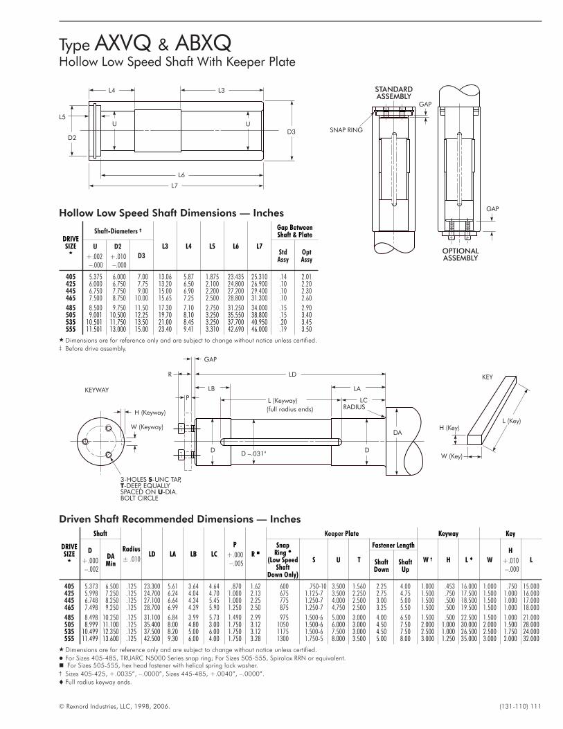
© Rexnord Industries, LLC, 1998, 2006. (131-110) 111
Type AXVQ & ABXQHollow Low Speed Shaft With Keeper Plate
Driven Shaft Recommended Dimensions — Inches
DRIVESIZE
�
Shaft
Radius
± .010LD LA LB LC
P
+.000–.005
R �
Keeper Plate Keyway Key
D
+.000–.002
DAMin
SnapRing �
(Low SpeedShaft
Down Only)
S U T
Fastener Length
W † H L � W
H
+.010–.000
LShaftDown
ShaftUp
405 5.373 6.500 .125 23.300 5.61 3.64 4.64 .870 1.62 600 .750-10 3.500 1.560 2.25 4.00 1.000 .453 16.000 1.000 .750 15.000425 5.998 7.250 .125 24.700 6.24 4.04 4.70 1.000 2.13 675 1.125-7 3.500 2.250 2.75 4.75 1.500 .750 17.500 1.500 1.000 16.000445 6.748 8.250 .125 27.100 6.64 4.34 5.45 1.000 2.25 775 1.250-7 4.000 2.500 3.00 5.00 1.500 .500 18.500 1.500 1.000 17.000465 7.498 9.250 .125 28.700 6.99 4.39 5.90 1.250 2.50 875 1.250-7 4.750 2.500 3.25 5.50 1.500 .500 19.500 1.500 1.000 18.000
485 8.498 10.250 .125 31.100 6.84 3.99 5.73 1.490 2.99 975 1.500-6 5.000 3.000 4.00 6.50 1.500 .500 22.500 1.500 1.000 21.000505 8.999 11.100 .125 35.400 8.00 4.80 3.00 1.750 3.12 1050 1.500-6 6.000 3.000 4.50 7.50 2.000 1.000 30.000 2.000 1.500 28.000535 10.499 12.350 .125 37.500 8.20 5.00 6.00 1.750 3.12 1175 1.500-6 7.500 3.000 4.50 7.50 2.500 1.000 26.500 2.500 1.750 24.000555 11.499 13.600 .125 42.500 9.30 6.00 4.00 1.750 3.28 1300 1.750-5 8.000 3.500 5.00 8.00 3.000 1.250 35.000 3.000 2.000 32.000
� Dimensions are for reference only and are subject to change without notice unless certified.
� For Sizes 405-485, TRUARC N5000 Series snap ring; For Sizes 505-555, Spirolox RRN or equivalent.� For Sizes 505-555, hex head fastener with helical spring lock washer.† Sizes 405-425, +.0035”, –.0000”, Sizes 445-485, +.0040”, –.0000”.
� Full radius keyway ends.
Hollow Low Speed Shaft Dimensions — Inches
DRIVESIZE
�
Shaft-Diameters ‡
L3 L4 L5 L6 L7
Gap BetweenShaft & Plate
U
+.002–.000
D2
+.010–.000
D3StdAssy
OptAssy
405 5.375 6.000 7.00 13.06 5.87 1.875 23.435 25.310 .14 2.01425 6.000 6.750 7.75 13.20 6.50 2.100 24.800 26.900 .10 2.20445 6.750 7.750 9.00 15.00 6.90 2.200 27.200 29.400 .10 2.30465 7.500 8.750 10.00 15.65 7.25 2.500 28.800 31.300 .10 2.60
485 8.500 9.750 11.50 17.30 7.10 2.750 31.250 34.000 .15 2.90505 9.001 10.500 12.25 19.70 8.10 3.250 35.550 38.800 .15 3.40535 10.501 11.750 13.50 21.00 8.45 3.250 37.700 40.950 .20 3.45555 11.501 13.000 15.00 23.40 9.41 3.310 42.690 46.000 .19 3.50
� Dimensions are for reference only and are subject to change without notice unless certified.‡ Before drive assembly.
D3UU
D2
L3
L6
L7
L4
L5
LD
LB LA
LC
DD
DA
L (Keyway)RADIUS
KEYWAY
H (Keyway)
W (Keyway)
3-HOLES -UNC TAP,-DEEP, EQUALLY
SPACED ON -DIA.BOLT CIRCLE
S
T
U
W (Key)
H (Key)L (Key)
D –.031"
R
P
GAP
KEY
(full radius ends)
GAP
OPTIONALASSEMBLY
STANDARDASSEMBLY
GAP
SNAP RING
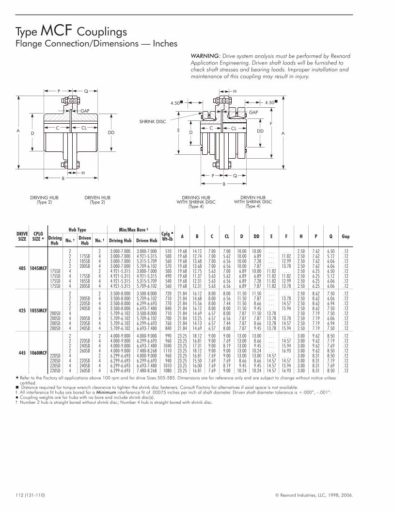
112 (131-110) © Rexnord Industries, LLC, 1998, 2006.
Type MCF CouplingsFlange Connection/Dimensions — Inches
DD
F
GAP
C CLE D
SHRINK DISC
A
P Q
B
HQP
GAP
C CLA
D
BH
DD
DRIVING HUBWITH SHRINK DISC
(Type 4)
DRIVEN HUBWITH SHRINK DISC
(Type 4)
DRIVEN HUB(Type 2)
DRIVING HUB(Type 2)
4.50� 4.50�
WARNING: Drive system analysis must be performed by RexnordApplication Engineering. Driven shaft loads will be furnished tocheck shaft stresses and bearing loads. Improper installation andmaintenance of this coupling may result in injury.
DRIVESIZE
CPLGSIZE �
Hub Type Min/Max Bore ‡
Cplg �
Wt-lbA B C CL D DD E F H P Q GapDriving
HubNo. † Driven
HubNo. † Driving Hub Driven Hub
405 1045MCF
2 2 3.000-7.000 3.000-7.000 510 19.68 14.12 7.00 7.00 10.00 10.00 . . . . . . 2.50 7.62 6.50 .122 175SD 4 3.000-7.000 4.921-5.315 500 19.68 12.74 7.00 5.62 10.00 6.89 . . . 11.82 2.50 7.62 5.12 .122 185SD 4 3.000-7.000 5.315-5.709 560 19.68 13.68 7.00 6.56 10.00 7.28 . . . 12.99 2.50 7.62 6.06 .122 200SD 4 3.000-7.000 5.709-6.102 570 19.68 13.68 7.00 6.56 10.00 7.87 . . . 13.78 2.50 7.62 6.06 .12
175SD 4 2 4.921-5.315 3.000-7.000 500 19.68 12.75 5.63 7.00 6.89 10.00 11.82 . . . 2.50 6.25 6.50 .12175SD 4 175SD 4 4.921-5.315 4.921-5.315 490 19.68 11.37 5.63 5.62 6.89 6.89 11.82 11.82 2.50 6.25 5.12 .12175SD 4 185SD 4 4.921-5.315 5.315-5.709 540 19.68 12.31 5.63 6.56 6.89 7.28 11.82 12.99 2.50 6.25 6.06 .12175SD 4 200SD 4 4.921-5.315 5.709-6.102 560 19.68 12.31 5.63 6.56 6.89 7.87 11.82 13.78 2.50 6.25 6.06 .12
425 1055MCF
2 2 3.500-8.000 3.500-8.000 720 21.84 16.12 8.00 8.00 11.50 11.50 . . . . . . 2.50 8.62 7.50 .122 200SD 4 3.500-8.000 5.709-6.102 710 21.84 14.68 8.00 6.56 11.50 7.87 . . . 13.78 2.50 8.62 6.06 .122 220SD 4 3.500-8.000 6.299-6.693 770 21.84 15.56 8.00 7.44 11.50 8.66 . . . 14.57 2.50 8.62 6.94 .122 240SD 4 3.500-8.000 6.693-7.480 840 21.84 16.12 8.00 8.00 11.50 9.45 . . . 15.94 2.50 8.62 7.50 .12
200SD 4 2 5.709-6.102 3.500-8.000 710 21.84 14.69 6.57 8.00 7.87 11.50 13.78 . . . 2.50 7.19 7.50 .12200SD 4 200SD 4 5.709-6.102 5.709-6.102 700 21.84 13.25 6.57 6.56 7.87 7.87 13.78 13.78 2.50 7.19 6.06 .12200SD 4 220SD 4 5.709-6.102 6.299-6.693 760 21.84 14.13 6.57 7.44 7.87 8.66 13.78 14.57 2.50 7.19 6.94 .12200SD 4 240SD 4 5.709-6.102 6.693-7.480 840 21.84 14.69 6.57 8.00 7.87 9.45 13.78 15.94 2.50 7.19 7.50 .12
445 1060MCF
2 2 4.000-9.000 4.000-9.000 990 23.25 18.12 9.00 9.00 13.00 13.00 . . . . . . 3.00 9.62 8.50 .122 220SD 4 4.000-9.000 6.299-6.693 960 23.25 16.81 9.00 7.69 13.00 8.66 . . . 14.57 3.00 9.62 7.19 .122 240SD 4 4.000-9.000 6.693-7.480 1040 23.25 17.31 9.00 8.19 13.00 9.45 . . . 15.94 3.00 9.62 7.69 .122 260SD 4 4.000-9.000 7.480-8.268 1110 23.25 18.12 9.00 9.00 13.00 10.24 . . . 16.93 3.00 9.62 8.50 .12
220SD 4 2 6.299-6.693 4.000-9.000 960 23.25 16.81 7.69 9.00 13.00 13.00 14.57 . . . 3.00 8.31 8.50 .12220SD 4 220SD 4 6.299-6.693 6.299-6.693 940 23.25 15.50 7.69 7.69 8.66 8.66 14.57 14.57 3.00 8.31 7.19 .12220SD 4 240SD 4 6.299-6.693 6.693-7.480 1010 23.25 16.00 7.69 8.19 9.45 9.45 14.57 15.94 3.00 8.31 7.69 .12220SD 4 260SD 4 6.299-6.693 7.480-8.268 1080 23.25 16.81 7.69 9.00 10.24 10.24 14.57 16.93 3.00 8.31 8.50 .12
� Refer to the Factory all applications above 100 rpm and for drive Sizes 505-585. Dimensions are for reference only and are subject to change without notice unlesscertified.� Distance required for torque wrench clearance to tighten the shrink disc fasteners. Consult Factory for alternatives if axial space is not available.‡ All interference fit hubs are bored for a Minimum interference fit of .00075 inches per inch of shaft diameter. Driven shaft diameter tolerance is +.000”, –.001”.� Coupling weights are for hubs with no bore and include shrink disc(s).† Number 2 hub is straight bored without shrink disc; Number 4 hub is straight bored with shrink disc.
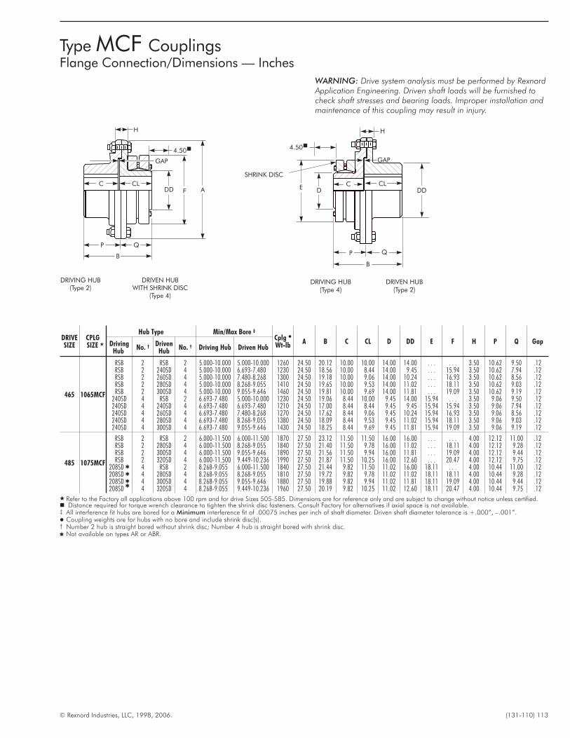
© Rexnord Industries, LLC, 1998, 2006. (131-110) 113
Type MCF CouplingsFlange Connection/Dimensions — Inches
H
4.50�
FDD
GAP
C CL
P Q
B
DRIVING HUB(Type 2)
DRIVEN HUBWITH SHRINK DISC
(Type 4)
A
GAP
CLDD
DRIVING HUB(Type 4)
DRIVEN HUB(Type 2)
CE D
SHRINK DISC
P Q
B
H
4.50�
WARNING: Drive system analysis must be performed by RexnordApplication Engineering. Driven shaft loads will be furnished tocheck shaft stresses and bearing loads. Improper installation andmaintenance of this coupling may result in injury.
DRIVESIZE
CPLGSIZE �
Hub Type Min/Max Bore ‡
Cplg �
Wt-lbA B C CL D DD E F H P Q GapDriving
HubNo. † Driven
HubNo. † Driving Hub Driven Hub
465 1065MCF
RSB 2 RSB 2 5.000-10.000 5.000-10.000 1260 24.50 20.12 10.00 10.00 14.00 14.00 . . . . . . 3.50 10.62 9.50 .12RSB 2 240SD 4 5.000-10.000 6.693-7.480 1230 24.50 18.56 10.00 8.44 14.00 9.45 . . . 15.94 3.50 10.62 7.94 .12RSB 2 260SD 4 5.000-10.000 7.480-8.268 1300 24.50 19.18 10.00 9.06 14.00 10.24 . . . 16.93 3.50 10.62 8.56 .12RSB 2 280SD 4 5.000-10.000 8.268-9.055 1410 24.50 19.65 10.00 9.53 14.00 11.02 . . . 18.11 3.50 10.62 9.03 .12RSB 2 300SD 4 5.000-10.000 9.055-9.646 1460 24.50 19.81 10.00 9.69 14.00 11.81 . . . 19.09 3.50 10.62 9.19 .12
240SD 4 RSB 2 6.693-7.480 5.000-10.000 1230 24.50 19.06 8.44 10.00 9.45 14.00 15.94 . . . 3.50 9.06 9.50 .12240SD 4 240SD 4 6.693-7.480 6.693-7.480 1210 24.50 17.00 8.44 8.44 9.45 9.45 15.94 15.94 3.50 9.06 7.94 .12240SD 4 260SD 4 6.693-7.480 7.480-8.268 1270 24.50 17.62 8.44 9.06 9.45 10.24 15.94 16.93 3.50 9.06 8.56 .12240SD 4 280SD 4 6.693-7.480 8.268-9.055 1380 24.50 18.09 8.44 9.53 9.45 11.02 15.94 18.11 3.50 9.06 9.03 .12240SD 4 300SD 4 6.693-7.480 9.055-9.646 1430 24.50 18.25 8.44 9.69 9.45 11.81 15.94 19.09 3.50 9.06 9.19 .12
485 1075MCF
RSB 2 RSB 2 6.000-11.500 6.000-11.500 1870 27.50 23.12 11.50 11.50 16.00 16.00 . . . . . . 4.00 12.12 11.00 .12RSB 2 280SD 4 6.000-11.500 8.268-9.055 1840 27.50 21.40 11.50 9.78 16.00 11.02 . . . 18.11 4.00 12.12 9.28 .12RSB 2 300SD 4 6.000-11.500 9.055-9.646 1890 27.50 21.56 11.50 9.94 16.00 11.81 . . . 19.09 4.00 12.12 9.44 .12RSB 2 320SD 4 6.000-11.500 9.449-10.236 1990 27.50 21.87 11.50 10.25 16.00 12.60 . . . 20.47 4.00 12.12 9.75 .12
208SD � 4 RSB 2 8.268-9.055 6.000-11.500 1840 27.50 21.44 9.82 11.50 11.02 16.00 18.11 . . . 4.00 10.44 11.00 .12208SD � 4 280SD 4 8.268-9.055 8.268-9.055 1810 27.50 19.72 9.82 9.78 11.02 11.02 18.11 18.11 4.00 10.44 9.28 .12208SD � 4 300SD 4 8.268-9.055 9.055-9.646 1880 27.50 19.88 9.82 9.94 11.02 11.81 18.11 19.09 4.00 10.44 9.44 .12208SD � 4 320SD 4 8.268-9.055 9.449-10.236 1960 27.50 20.19 9.82 10.25 11.02 12.60 18.11 20.47 4.00 10.44 9.75 .12
� Refer to the Factory all applications above 100 rpm and for drive Sizes 505-585. Dimensions are for reference only and are subject to change without notice unless certified.� Distance required for torque wrench clearance to tighten the shrink disc fasteners. Consult Factory for alternatives if axial space is not available.‡ All interference fit hubs are bored for a Minimum interference fit of .00075 inches per inch of shaft diameter. Driven shaft diameter tolerance is +.000”, –.001”.� Coupling weights are for hubs with no bore and include shrink disc(s).† Number 2 hub is straight bored without shrink disc; Number 4 hub is straight bored with shrink disc.� Not available on types AR or ABR.
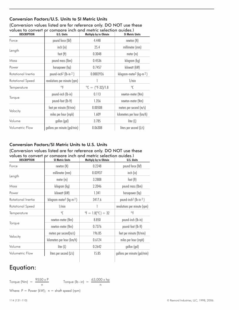
114 (131-110) © Rexnord Industries, LLC, 1998, 2006.
Conversion Factors/U.S. Units to SI Metric Units
(Conversion values listed are for reference only. DO NOT use thesevalues to convert or compare inch and metric selection guides.)
DESCRIPTION U.S. Units Multiply by to Obtain SI Metric Units
Force pound force (lbf) 4.448 newton (N)
Lengthinch (in) 25.4 millimeter (mm)
foot (ft) 0.3048 meter (m)
Mass pound mass (lbm) 0.4536 kilogram (kg)
Power horsepower (hp) 0.7457 kilowatt (kW)
Rotational Inertia pound-inch2 (lb-in 2 ) 0.0002926 kilogram-meter2 (kg-m 2 )
Rotational Speed revolutions per minute (rpm) 1 1/min
Temperature ºF ºC = (ºF-32)/1.8 ºC
Torquepound-inch (lb-in) 0.113 newton-meter (Nm)
pound-foot (lb-ft) 1.356 newton-meter (Nm)
Velocityfeet per minute (ft/min) 0.00508 meters per second (m/s)
miles per hour (mph) 1.609 kilometers per hour (km/h)
Volume gallon (gal) 3.785 liter (L)
Volumetric Flow gallons per minute (gal/min) 0.06308 liters per second (L/s)
Conversion Factors/SI Metric Units to U.S. Units
(Conversion values listed are for reference only. DO NOT use thesevalues to convert or compare inch and metric selection guides.)
DESCRIPTION SI Metric Units Multiply by to Obtain U.S. Units
Force newton (N) 0.2248 pound force (lbf)
Lengthmillimeter (mm) 0.03937 inch (in)
meter (m) 3.2808 foot (ft)
Mass kilogram (kg) 2.2046 pound mass (lbm)
Power kilowatt (kW) 1.341 horsepower (hp)
Rotational Inertia kilogram-meter2 (kg-m 2 ) 3417.6 pound-inch2 (lb-in 2 )
Rotational Speed 1/min 1 revolutions per minute (rpm)
Temperature ºC ºF = 1.8(ºC ) + 32 ºF
Torquenewton-meter (Nm) 8.850 pound-inch (lb-in)
newton-meter (Nm) 0.7376 pound-foot (lb-ft)
Velocitymeters per second(m/s) 196.85 feet per minute (ft/min)
kilometers per hour (km/h) 0.6124 miles per hour (mph)
Volume liter (L) 0.2642 gallon (gal)
Volumetric Flow liters per second (L/s) 15.85 gallons per minute (gal/min)
Equation:
Torque (Nm) =9550 x P
nTorque (lb - in) =
63,000 x hp
n
Where: P = Power (kW); n = shaft speed (rpm)

© Rexnord Industries, LLC, 1998, 2006. (131-110) 115
THIS PAGE INTENTIONALLY LEFT BLANK
For more than 100 years, the dedicated people of Rexnord
have delivered excellence in quality and service to our
customers around the globe. Rexnord is a trusted name when
it comes to providing skillfully engineered products that
improve productivity and efficiency for industrial applications
worldwide. We are committed to exceeding customer
expectations in every area of our business: product design,
application engineering, operations, and customer service.
Because of our customer focus, we are able to thoroughly
understand the needs of your business and have the resources
available to work closely with you to reduce maintenance
costs, eliminate redundant inventories and prevent equipment
down time.
Rexnord represents the most comprehensive portfolio of power
transmission and conveying components in the world with the
brands you know and trust.
World Class Customer Service
AAUUSSTTRRAALLIIAARexnord Australia Pty. Ltd.
Picton, New South Wales
Phone: 61-2-4677-3811
Fax: 61-2-4677-3812
BBRRAAZZIILLRexnord Correntes Ltda.
Sao Leopoldo - RS
Phone: 55-51-579-8022
Fax: 55-51-579-8029
CCAANNAADDAARexnord Canada Ltd.
Scarborough, Ontario
Phone: 1-416-297-6868
Fax: 1-416-297-6873
CCHHIINNAARexnord China
Shanghai, China
Phone: 86-21-62701942
Fax: 86-21-62701943
EEUURROOPPEERexnord NV/SA
Mechelen, Belgium
Phone: 32-15-.443811
Fax: 32-15-443860
Rexnord Kette GmbH
Betzdorf, Germany
Phone: 49-2741-2840
Fax: 49-2741-284-385
LLAATTIINN AAMMEERRIICCAARexnord International, Inc.
Milwaukee, Wisconsin
Phone: 1-414-643-2366
Fax: 1-414-643-3222
E-mail: [email protected]
MMEEXXIICCOORexnord S.A. de C.V.
Queretaro, Qro.
Phone: 52-442-218.5000
Fax: 52-.442-218-1090
SSIINNGGAAPPOORREERexnord International, Inc.
Singapore City, Singapore
Phone: 65-6338-5622
Fax: 65-6338-5422
UUNNIITTEEDD SSTTAATTEESSCustomer Service
Phone: 1-866-REXNORD
(1-866-739-6673)
Fax: 1-614-675-1898
E-mail: rexnordcs(state)@rexnord.com
Example: [email protected]
AALLLL CCOOUUNNTTRRIIEESS NNOOTT LLIISSTTEEDDRexnord International
Milwaukee, Wisconsin
Phone: 1-414-643-2366
Fax: 1-414-643-3222
E-mail: [email protected]
WORLDWIDE CUSTOMER SERVICE
131-110 09/2006 Delzer Litho Printed in USARexnord Industries, LLC, Gear Group, 3001 West Canal Street, Milwaukee, WI 53208-4200 USA
Phone: 414-342-3131 Fax: 414-937-4359
© 2007 Rexnord Industries LLC
A+Plus and Rexnord are registered trademarks of Rexnord Industries, LLC. Viton is a registered trademark of DuPont. Falk
and Magnum are trademarks of Rexnord. All rights reserved.