a practical guide to ‘free energy’ devices - mareasistemi hho generator for car.pdf · a...
TRANSCRIPT
A Practical Guide to ‘Free Energy’ Devices
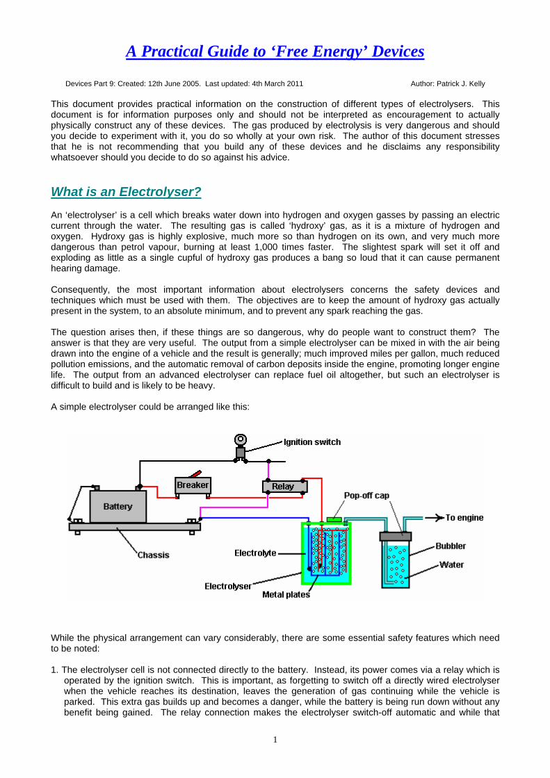
Devices Part 9: Created: 12th June 2005. Last updated: 4th March 2011 Author: Patrick J. Kelly This document provides practical information on the construction of different types of electrolysers. This document is for information purposes only and should not be interpreted as encouragement to actually physically construct any of these devices. The gas produced by electrolysis is very dangerous and should you decide to experiment with it, you do so wholly at your own risk. The author of this document stresses that he is not recommending that you build any of these devices and he disclaims any responsibility whatsoever should you decide to do so against his advice. What is an Electrolyser? An ‘electrolyser’ is a cell which breaks water down into hydrogen and oxygen gasses by passing an electric current through the water. The resulting gas is called ‘hydroxy’ gas, as it is a mixture of hydrogen and oxygen. Hydroxy gas is highly explosive, much more so than hydrogen on its own, and very much more dangerous than petrol vapour, burning at least 1,000 times faster. The slightest spark will set it off and exploding as little as a single cupful of hydroxy gas produces a bang so loud that it can cause permanent hearing damage. Consequently, the most important information about electrolysers concerns the safety devices and techniques which must be used with them. The objectives are to keep the amount of hydroxy gas actually present in the system, to an absolute minimum, and to prevent any spark reaching the gas. The question arises then, if these things are so dangerous, why do people want to construct them? The answer is that they are very useful. The output from a simple electrolyser can be mixed in with the air being drawn into the engine of a vehicle and the result is generally; much improved miles per gallon, much reduced pollution emissions, and the automatic removal of carbon deposits inside the engine, promoting longer engine life. The output from an advanced electrolyser can replace fuel oil altogether, but such an electrolyser is difficult to build and is likely to be heavy. A simple electrolyser could be arranged like this:
While the physical arrangement can vary considerably, there are some essential safety features which need to be noted: 1. The electrolyser cell is not connected directly to the battery. Instead, its power comes via a relay which is
operated by the ignition switch. This is important, as forgetting to switch off a directly wired electrolyser when the vehicle reaches its destination, leaves the generation of gas continuing while the vehicle is parked. This extra gas builds up and becomes a danger, while the battery is being run down without any benefit being gained. The relay connection makes the electrolyser switch-off automatic and while that
1
2
sounds like a minor thing, it most definitely is not. An even better connection for the relay is to wire it across the electrical fuel pump as that powers down automatically if the engine stalls with the ignition on.
2. The electrical supply to the electrolyser then passes through a resettable circuit-breaker. This is also an
important feature because, should any malfunction occur in the electrolyser cell which causes a continuously increasing current to be drawn (such as undue overheating of the cell), then the circuit breaker disconnects the link and prevents any serious problem arising. A light-emitting diode with a current limiting resistor of say, 680 ohms in series with it, can be wired directly across the contacts of the circuit breaker. The Light-Emitting Diode can be mounted on the dashboard. As the contacts are normally closed, they short-circuit the LED and so no light shows. If the circuit-breaker is tripped, then the LED will light up to show that the circuit-breaker has operated. The current through the LED is so low that the electrolyser is effectively switched off.
3. Both the electrolyser and the ’bubbler’ have tightly fitting ‘pop-off’ caps. This is very important. If the
hydroxy gas above the surface of the liquid were to be ignited and the unit were robustly sealed, then the pressure build up inside the unit would be very rapid and it would explode like a grenade. If however, ‘pop-off’ caps are installed, then as the pressure starts to build up, the cap is displaced, maintaining the integrity of the unit, and preventing excessive pressure build-up. Having said that, it is a major objective to avoid gas ignition in the first place.
4. The wires going to the plates inside the electrolyser are both connected well below the surface of the
liquid. This is to avoid the possibility of a connection working loose with the vibration of the vehicle and causing a spark in the gas-filled region.
5. The volume above the surface of the liquid is kept as low as possible to minimise the size of an explosion
in the unlikely event of one occurring in spite of all of the precautions. Some experimenters like to reduce the volume above the liquid surface by filling it with polystyrene ‘beans’. I am not happy with that arrangement as polystyrene is a material with major electrostatic properties. Massive charges build up rapidly on polystyrene, and while the damp conditions inside the electrolyser are not particularly suitable to electrostatic sparks, I feel that the risk of explosion is greater with moving pieces of polystyrene inside the cell.
6. Finally, the hydroxy gas is passed through a ‘bubbler’ before being fed to the engine. A bubbler is just a
tall and narrow container of water with the gas being fed into it near the bottom, and forced to rise through the water before continuing it’s journey to the engine. If, for any reason, the gas in the pipe feeding the engine is ignited, then the gas above the water in the bubbler will be ignited. That will blow the cap off the bubbler, restrict the explosion to a small amount of gas, and the water column in the bubbler prevents the gas in the electrolyser from being ignited. People have suggested using flashback arrestors from gas-welding equipment but these are far too slow to work with hydroxy gas where the flame front moves at a thousand metres per second. So the best practice is to use one, or more, bubblers as they are easy to make and install and are very reliable.
Different Types of Electrolyser There are three main types of electrolyser: 1. 12 Volt Single Cell. 2. 12 Volt Series Cell. 3. High-Voltage Series Cell. Each of these will be covered in detail in the remainder of this document. Certain principles apply to each type and will be covered after the three descriptions. These include the necessary surface area of each electrode, the ‘conditioning’ of the electrodes and dealing with bubbles.

12 Volt Single Cells The most simple electrolyser to construct is the single cell version as shown above. This can use any size and shape of container which makes is convenient for mounting in the engine compartment of the vehicle. Many people opt for a cylindrical container as these are widely available and are easier to mount, possibly as shown here:
Finding space in the engine compartment is one of the more difficult tasks with European cars as their designs tend to pack the engine area tightly to reduce the size of the vehicle to a minimum. The rate of gas production depends on a number of factors: 1. The liquid used for electrolysis. If distilled water is used, then almost no current will flow through the cell as
distilled water has a very high resistance to current flow, and almost no gas will be produced. It is normal practice to add some other substance to the water to increase the rate of gas production.
If salt is added to the water, the rate of electrolysis increases enormously. However, that is not a good choice of additive as the salt forms a corrosive mixture and Chlorine gas is produced along with the Hydrogen and Oxygen gasses. The same goes for battery acid; it does work but it is a very poor choice which causes practical problems over a period of time. Other additives will create the increase in gas production but have similar undesirable effects. Two additives stand out as being the best choices. The first is Sodium Hydroxide (chemical symbol NaOH), sometimes called ‘lye’. The very best choice is Potassium Hydroxide (chemical symbol KOH) which is available in pellet form. Potassium Hydroxide acts as a catalyst in the process of electrolysis in that it promotes the gas production but does not get used up in the process.
2. The spacing of the electrode plates. The closer together the plates are placed, the greater the rate of gas
production. There is a practical limit to this, as bubbles of gas formed between the plates have to be able to escape and rise to the surface. The optimum spacing is generally considered to be 3 mm or 1/8 inch, although some people prefer to have a 5 mm gap between the plates. These plates are typically made from 316 grade stainless steel.
3. The area of the electrode plates and the preparation of the plate surface. The greater the plate area, the
greater the rate of gas production. Some of this effect may be due to the improvement in the chances of bubbles escaping from the plates and not blocking some of the plate area. It is recommended that each face of every electrode plate has an area of between two and four square inches (13 and 25 square centimetres) per amp of current flowing through the cell.
The preparation of the surface of the plates has a major effect on the rate of gas production. A major improvement is achieved if both sides of each plate are sanded in a criss-cross pattern (this produces an increased surface area with thousands of microscopic peaks which help bubbles form and leave the plate). The plates are then assembled and immersed in the electrolyte solution for about three days. This creates a protective white coating on the surface of the plates which helps enhance the electrolysis. The plates are then rinsed off with distilled water and the cell is refilled with a fresh solution of electrolyte.
3

4. The current flowing through the cell. This is an absolutely key factor in gas production, and one of the most difficult to control accurately and economically. The greater the current, the greater the rate of gas production. The current is controlled by the concentration of Potassium Hydroxide in the electrolyte (water plus KOH) and the voltage across the cell. The voltage across the cell has limited effect as it reaches a maximum at just 1.24 volts. Up to that point, an increase in voltage causes an increase in gas production rate. Once the voltage gets over 1.24 volts, increasing it further produces no further increase in the rate of gas production.
If the voltage is increased above 1.24 volts, the extra voltage goes to heat the electrolyte. Assume that the current through the cell is 10 amps. In that case, the power used to produce gas is 10 amps x 1.24 volts = 12.4 watts. When the engine is running, the voltage at the battery terminals will be about 13.8 volts as the alternator provides the extra voltage to drive current into the battery. The excess voltage applied to the cell is about 1.24 less than that, say 12.5 volts. The power which heats the electrolyte is about 12.5 volts x 10 amps = 125 watts. That is ten times the power being used to produce gas. This is very, very inefficient. The following diagram may help you understand the situation:
The best electrode material for the plates is 316L-grade stainless steel. It is hard to believe, but there is a voltage drop across the plate, which makes it necessary to apply about 2 volts to the plates on each side of the cell. So, if you are running off 12 volts, then six cells in a row across the battery gives the maximum possible drive. With the engine running and providing almost 14 volts, seven cells gives the highest possible drive. The electrolyte heating up is a wholly bad thing as it drives a good deal of water vapour out of the electrolyte and this mixes with the gas and is fed to the engine. Injecting water mist, which is a fine spray of water droplets, into an engine increases its performance due to the water expanding when it is heated. This improves both the engine power and the miles per gallon, and it makes the engine run cooler, which improves the life of the engine. But water vapour is a bad thing as it is already fully expanded and just gets in the way of the hydroxy gas, diluting it and lowering the power of the engine with no benefit at all.. As the voltage applied to the cell is pretty much fixed, the current flow is controlled by the concentration of Potassium Hydroxide in the electrolyte and the plate area. Once the cell is built, the plate area is fixed, so the current is adjusted by controlling the amount of KOH added to the water. There is a slight limit to this, in that the gas production increases with KOH concentration until the concentration reaches 28% (by weight). After that point, any increase in the concentration produces a reduction in the rate of gas production. General practice is to have a fairly low concentration of KOH which is found by trial. Bob Boyce, who is very experienced in this field, says that you should never add water to NaOH or KOH. Always start with water, and add the chemical to the water SLOWLY, stirring well and allowing the mixture to cool in between additions. Shelf life depends on how well it is sealed from the atmosphere. Carbon is an enemy to this process. Whether the KOH is in dry or liquid form, it will absorb carbon from CO2 in the atmosphere, or any other source of free carbon. As this happens, the catalytic effect is diminished. The more carbon is absorbed, the less the catalytic efficiency of the electrolyte. So, if you wish to maintain maximum performance, it is crucial to keep air out of your dry or liquid chemical storage containers, AND away from the electrolyte in your cells.
4

5. The temperature of the electrolyte. The hotter the electrolyte, the higher the current carried through it. This can be a snag. Suppose it is decided that the current through the cell is to be 10 amps and the electrolyte concentration adjusted to give that current when the engine is started. As time passes, the 125 watts of excess power drawn from the battery, heats the electrolyte, which in turn causes an increase in the current flowing through the cell, which causes even greater heating, which..... The result is positive feedback which causes a runaway temperature effect.
This effect is aggravated by the water in the cell being used up as the vehicle drives along. This raises the concentration of the electrolyte because the amount of KOH remains the same while the amount of water reduces. There are different ways of dealing with this problem. One is to reduce the concentration of KOH so that the chosen current is only reached when the electrolyte has reached its maximum working temperature. This is a simple solution with the slight disadvantage that the gas production rate when starting is lower than it could be. However, the heating power is so high that it will not be long until the cell is operating at its maximum temperature. A different way to handle the problem is to use an electronic circuit to limit the current through the cell to the chosen value by dropping the voltage applied to the cell. This has the disadvantage that the extra power is being dissipated in the electronics which then has a heat problem. Also, this solution does not improve the overall efficiency of the process. The best way of all is to reduce the voltage applied to the cell by using more than one cell connected in a daisy-chain across the battery. With two cells, each will get about seven volts across it and the gas production will be doubled. If space in the engine compartment allows, a chain of six cells can be used which means each receives about two volts and the waste powers is reduced to some 10.6 watts per cell, while the gas production is six times higher. With the higher rate of gas production, it would probably be possible to reduce the chosen current flowing through the cell. Also, with six cells, the amount of water is six times greater and so there will be less concentrating of the electrolyte due to the water being used up. This is a “Series-Cell” arrangement.
6. The number of bubbles sticking to the surface of the electrode plates. This is generally considered to be a
significant problem. Many methods have been used to deal with it. Some people use magnets, others pump the electrolyte around to dislodge the bubbles, others use buzzers to vibrate the plates and some pulse the voltage to the cell at just the right frequency to vibrate the cell. Once the plates have become fully "conditioned" bubbles break away from them very easily and there is no need for any dislodging mechanism.
12 Volt Series Cells If there is room in the engine compartment, then anything up to seven of these cells may be installed and connected in series across the battery. The pipework is daisy-chained from cell to cell so that the air drawn into the engine passes through each cell, picking up more and more gas on the way, as shown here:
5
The upper diagram shows the electrical connection between the cells while the lower diagram shows how the air/gas pipes are connected. While the cells are shown side by side in the diagram, they can be positioned in any convenient locations in the engine compartment. As the temperature in the engine compartment can be quite high, the cell housings need to be unaffected by high temperatures, which make some plastic containers unsuitable for this use.
The volume of electrolyte contained in the cells of this type is considerable, so topping up the cells would not be an urgent matter. The picture above is expanded to give a better view. The actual gap between the plates will be about 5 mm or so, which means that the plate assembly shown above will only have a vertical height of about 1.5 inches (40 mm). The cell housing is likely to be eight or nine inches tall (200 mm) so the amount of electrolyte above the plates is considerable. The electrode area in this single cell electrolyser is about 6 x 6.4 = 38.4 square inches (248 sq. cm.). For maximum gas output, the electrolyte in each cell only needs 1.24 volts across it. If stainless steel electrodes are used, then the voltage drop across those electrodes makes the ideal voltage applied to the cell to be 2.0 volts. If the vehicle alternator is connected across the cell, then it will be receiving about 13.8 volts. Only 1.24 volts is used to make gas, the rest goes to heat the electrolyte. If the concentration of the electrolyte is adjusted to give 10 amps flowing through the cell, then 1.24 volts x 10 amps = 12.4 watts will be used to produce gas, and (13.8 - 1.24) volts x 10 amps = 125.6 watts will just heat the electrolyte. To put that another way: less than 10% of the power taken from the alternator will be used to make gas. High-Voltage Series Cells The electrolysers discussed above are used to improve the performance and efficiency of internal combustion engines running on fossil fuels. The optimum situation would be where the original fossil fuel can be dispensed with altogether and the engine run on water alone. This is not easy to do. It is not impossible to do. A few people have done it. The electrolyser described below is capable of running a suitable internal combustion engine. Excluding fossil fuels altogether does not cause any additional rust in the exhaust system or elsewhere in the vehicle since burning fossil fuels produces just as much water. Not every engine is suitable for conversion as the current types which have computer control of the amount of fuel passed to the engine, the timing of the spark and which used oxygen sensors to determine how the fuel burn inside the engine is going, are not suitable unless the present ignition-control system is controlled. One reason for this is that hydroxy gas burns a thousand times faster than fossil fuel vapour does. Consequently, the spark inside the cylinder has to occur later in the cycle, definitely after Top Dead Centre and probably about twelve degrees after TDC. The easiest vehicles to convert are the older types with Capacitor Discharge ignition or types which have a contact-breaker in the ignition circuit. These types generally have the ability to manually adjust the timing to whatever setting is needed. Ideally, the engine will have a carburettor and fair amount of spare space in the engine compartment. It would be an advantage if the engine capacity were not large, as the larger the engine, the greater the amount of hydroxy gas needed to run it. To increase the amount of gas produced by a DC electrolyser, it is necessary to increase the current through the cells by a major amount or increase the number of cells in the electrolyser, or both.
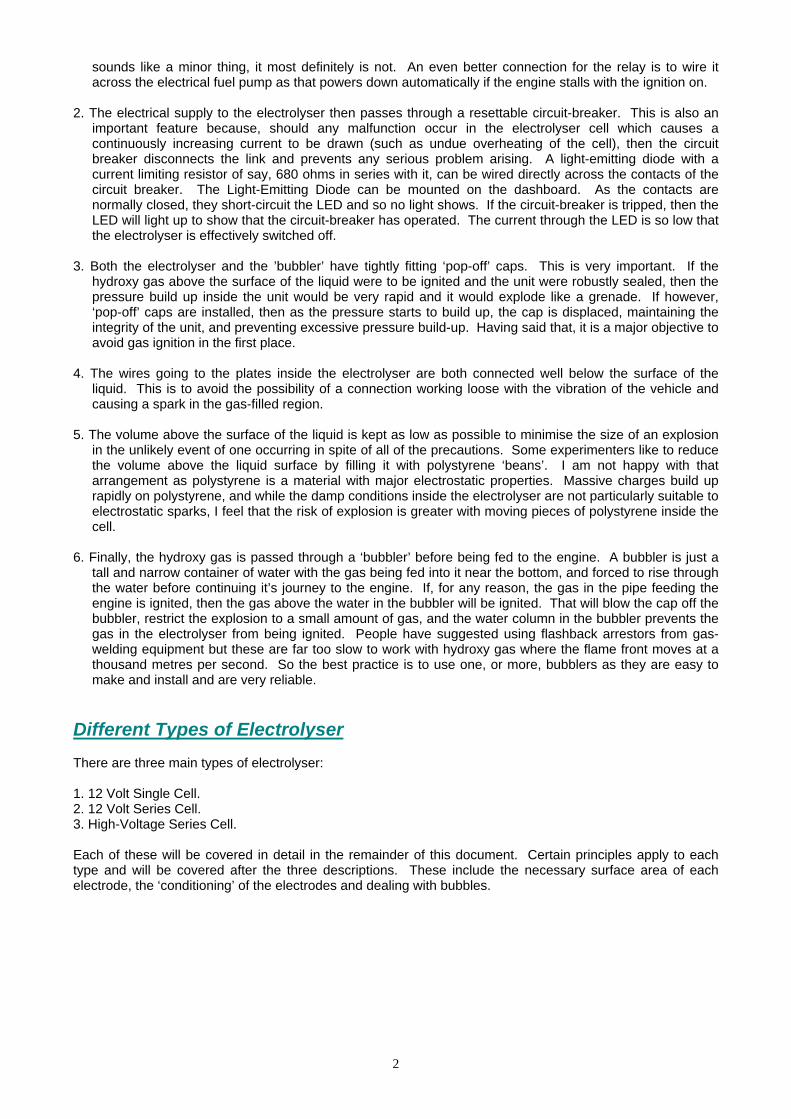
Bob Boyce is easily the most experienced and knowledgeable series-cell designer at the present time, and sincere thanks are due to him for sharing his design freely with everybody and for his continuous help, advice and support of the builders of electrolysers. Bob achieves a massively increased gas production rate by using an electrolyser with a large number of cells in it. Bob’s electrolyser is easily the most effective available at this time. It uses one hundred cells (101 plates) and applies a sophisticated pulsing waveform which raises the operational efficiency far above that envisioned by the science textbooks available today. Units with just 60 cells are inclined more to brute-force DC electrolysis, tending to mask the gains produced by pulsing. As there is a voltage drop across each stainless steel electrode plate, it is usual to allow about 2 volts across each cell for DC operation. However, Bob finds that for high-efficiency pulsing, the optimum voltage for each cell with 316L-grade stainless-steel electrode plates is about 1.5 volts. This means that a voltage of about 1.5 x 100 = 150 volts is needed to power it to its maximum pulsed output.
6
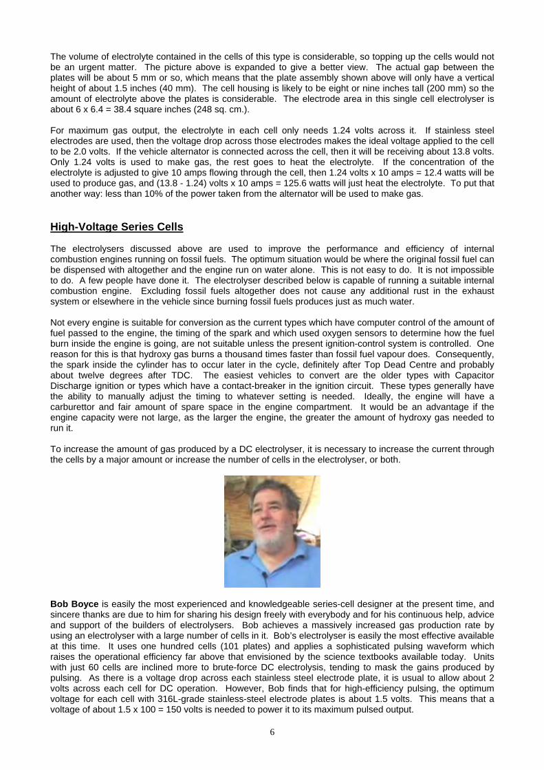
To get this higher voltage, Bob uses a 110 Volt inverter. An inverter is an electronic circuit which has a 12 Volt DC input and generates a 110 Volt AC output. These are readily available for purchase as they are used to run (US) mains equipment from car batteries. The output from the inverter is converted from Alternating Current to pulsing Direct Current by passing the output through four diodes in what is called a ‘Diode Bridge’. These are readily available at very low cost from electronic component suppliers. Obviously, it would not be practical to use a hundred self-contained cells daisy-chained together to act as the series-connected electrolyser cell. There would not be enough physical space in the engine compartment for that, so a different style of cell construction is needed. The view looking down on several separate electrolyser cells could be represented something like this:
Here the plus side of each cell is connected to the minus side of the next cell to provide a set of six interconnected cells acting in series. The current flowing through the electrolyser goes through each cell in turn and so each cell receives exactly the same current as the other cells. This is the same sort of arrangement as using six self-contained cells in a daisy-chain. To reduce the physical size of the unit, it is possible to construct the electrolyser as shown here:
In this arrangement, the individual cells have just one positive plate and one negative plate. The plates slot into the sides and bottom of the housing so that the electrolyte is trapped between the plates and an air gap is formed between the plus plate of one cell and the minus plate of the next cell. These air gaps are wasted space. They contribute nothing to the operation of the electrolyser. Each consists of a metal plate, a gap and a wire connection to the next metal plate. From an electrical point of view, the two metal plates at the opposite ends of these gaps, being connected by a wire link, are effectively the same plate (it is just a very thick, hollow plate). These air gaps might as well be eliminated which would save one metal plate and one wire link per cell. This can be difficult to visualise, but it produces an arrangement as shown here:
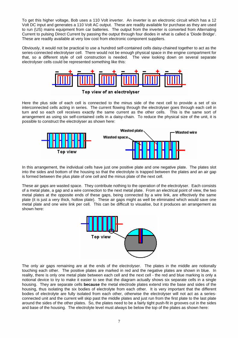
The only air gaps remaining are at the ends of the electrolyser. The plates in the middle are notionally touching each other. The positive plates are marked in red and the negative plates are shown in blue. In reality, there is only one metal plate between each cell and the next cell - the red and blue marking is only a notional device to try to make it easier to see that the diagram actually shows six separate cells in a single housing. They are separate cells because the metal electrode plates extend into the base and sides of the housing, thus isolating the six bodies of electrolyte from each other. It is very important that the different bodies of electrolyte are fully isolated from each other, otherwise the electrolyser will not act as a series-connected unit and the current will skip past the middle plates and just run from the first plate to the last plate around the sides of the other plates. So, the plates need to be a fairly tight push-fit in grooves cut in the sides and base of the housing. The electrolyte level must always be below the top of the plates as shown here:
7
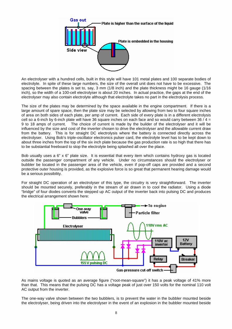
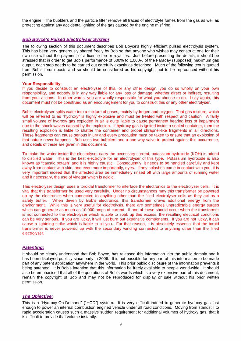
An electrolyser with a hundred cells, built in this style will have 101 metal plates and 100 separate bodies of electrolyte. In spite of these large numbers, the size of the overall unit does not have to be excessive. The spacing between the plates is set to, say, 3 mm (1/8 inch) and the plate thickness might be 16 gauge (1/16 inch), so the width of a 100-cell electrolyser is about 20 inches. In actual practice, the gaps at the end of the electrolyser may also contain electrolyte although that electrolyte takes no part in the electrolysis process. The size of the plates may be determined by the space available in the engine compartment. If there is a large amount of spare space, then the plate size may be selected by allowing from two to four square inches of area on both sides of each plate, per amp of current. Each side of every plate is in a different electrolysis cell so a 6-inch by 6-inch plate will have 36 square inches on each face and so would carry between 36 / 4 = 9 to 18 amps of current. The choice of current is made by the builder of the electrolyser and it will be influenced by the size and cost of the inverter chosen to drive the electrolyser and the allowable current draw from the battery. This is for straight DC electrolysis where the battery is connected directly across the electrolyser. Using Bob’s triple-oscillator electronics pulser card, the electrolyte level has to be kept down to about three inches from the top of the six inch plate because the gas production rate is so high that there has to be substantial freeboard to stop the electrolyte being splashed all over the place. Bob usually uses a 6” x 6” plate size. It is essential that every item which contains hydroxy gas is located outside the passenger compartment of any vehicle. Under no circumstances should the electrolyser or bubbler be located in the passenger area of the vehicle, even if pop-off caps are provided and a second protective outer housing is provided, as the explosive force is so great that permanent hearing damage would be a serious possibility. For straight DC operation of an electrolyser of this type, the circuitry is very straightforward. The inverter should be mounted securely, preferably in the stream of air drawn in to cool the radiator. Using a diode “bridge” of four diodes converts the stepped up AC output of the inverter back into pulsing DC and produces the electrical arrangement shown here:
As mains voltage is quoted as an average figure (“root-mean-square”) it has a peak voltage of 41% more than that. This means that the pulsing DC has a voltage peak of just over 150 volts for the nominal 110 volt AC output from the inverter. The one-way valve shown between the two bubblers, is to prevent the water in the bubbler mounted beside the electrolyser, being driven into the electrolyser in the event of an explosion in the bubbler mounted beside
8
9
the engine. The bubblers and the particle filter remove all traces of electrolyte fumes from the gas as well as protecting against any accidental igniting of the gas caused by the engine misfiring. Bob Boyce’s Pulsed Electrolyser System The following section of this document describes Bob Boyce’s highly efficient pulsed electrolysis system. This has been very generously shared freely by Bob so that anyone who wishes may construct one for their own use without the payment of a licence fee or royalties. Just before presenting the details, it should be stressed that in order to get Bob’s performance of 600% to 1,000% of the Faraday (supposed) maximum gas output, each step needs to be carried out carefully exactly as described. Much of the following text is quoted from Bob’s forum posts and so should be considered as his copyright, not to be reproduced without his permission. Your Responsibility: If you decide to construct an electrolyser of this, or any other design, you do so wholly on your own responsibility, and nobody is in any way liable for any loss or damage, whether direct or indirect, resulting from your actions. In other words, you are wholly responsible for what you choose to do. I say again, this document must not be construed as an encouragement for you to construct this or any other electrolyser. Bob’s electrolyser splits water into a mixture of gases, mainly hydrogen and oxygen. That gas mixture, which will be referred to as “hydroxy” is highly explosive and must be treated with respect and caution. A fairly small volume of hydroxy gas exploded in air is quite liable to cause permanent hearing loss or impairment due to the shock waves caused by the explosion. If hydroxy gas is ignited inside a sealed container, then the resulting explosion is liable to shatter the container and propel shrapnel-like fragments in all directions. These fragments can cause serious injury and every precaution must be taken to ensure that an explosion of that nature never happens. Bob uses two bubblers and a one-way valve to protect against this occurrence, and details of these are given in this document. To make the water inside the electrolyser carry the necessary current, potassium hydroxide (KOH) is added to distilled water. This is the best electrolyte for an electrolyser of this type. Potassium hydroxide is also known as “caustic potash” and it is highly caustic. Consequently, it needs to be handled carefully and kept away from contact with skin, and even more importantly, eyes. If any splashes come in contact with you, it is very important indeed that the affected area be immediately rinsed off with large amounts of running water and if necessary, the use of vinegar which is acidic. This electrolyser design uses a toroidal transformer to interface the electronics to the electrolyser cells. It is vital that this transformer be used very carefully. Under no circumstances may this transformer be powered up by the electronics when connected to anything other than the filled electrolyser cells as they act as a safety buffer. When driven by Bob’s electronics, this transformer draws additional energy from the environment. While this is very useful for electrolysis, there are sometimes unpredictable energy surges which can generate as much as 10,000 amps of current. If one of these should occur when the transformer is not connected to the electrolyser which is able to soak up this excess, the resulting electrical conditions can be very serious. If you are lucky, it will just burn out expensive components. If you are not lucky, it can cause a lightning strike which is liable to hit you. For that reason, it is absolutely essential that the toroid transformer is never powered up with the secondary winding connected to anything other than the filled electrolyser. Patenting: It should be clearly understood that Bob Boyce, has released this information into the public domain and it has been displayed publicly since early in 2006. It is not possible for any part of this information to be made part of any patent application anywhere in the world. This prior public disclosure of the information prevents it being patented. It is Bob’s intention that this information be freely available to people world-wide. It should also be emphasised that all of the quotations of Bob’s words which is a very extensive part of this document, remain the copyright of Bob and may not be reproduced for display or sale without his prior written permission. The Objective: This is a “Hydroxy-On-Demand” (“HOD”) system. It is very difficult indeed to generate hydroxy gas fast enough to power an internal combustion engined vehicle under all road conditions. Moving from standstill to rapid acceleration causes such a massive sudden requirement for additional volumes of hydroxy gas, that it is difficult to provide that volume instantly.

10
A better solution is to use an electric engine for the vehicle. This can be an electric vehicle which was designed from scratch as such, or it can be a standard vehicle which has been adapted for electric engine use. These electric vehicles are usually limited in how far they can travel, but a good solution to this is to use an electrical generator to charge the batteries, both when the vehicle is in use and when it is parked. This electrolyser can be used to run such a generator on water. With this arrangement, there are no CO2 emissions and the vehicle is very environmentally friendly. The batteries provide the necessary sudden acceleration demands and the generator recharges the batteries during normal driving. Overview: Bob’s pulsed system has the following components: 1. An electrical connection to the vehicle’s electrical system (with safety features built in). 2. An “inverter” which raises the electrolyser voltage to 160 volts. 3. Bob’s specially designed circuit board which generates a complicated water-splitting waveform. 4. Bob’s specially designed toroidal transformer which links Bob’s circuit board to the electrolyser. 5. Bob’s specially prepared 101-plate series-connected electrolyser. 6. A dual-protection system for linking the electrolyser safely to the internal combustion engine. None of these items is particularly difficult to achieve, but each needs to be done carefully and exactly as described, paying particular attention to the detailed instructions. Building the Case: The case needs to have very accurate slots cut in it. If you do not have a milling machine, then you should consider getting a fabrication shop to mill the slots for you. The case has two ends, two sides, one base and one lid. Of these, the two sides and the base need 101 accurate grooves cut in them. The grooves are there to hold the electrode plates securely in position, and have to be cut extremely accurately. The groove width is set at 0.0003" less than the actual, measured plate thickness. This prevents any electrical flow around the plates. If you do not have the equipment to do this, then there is an enthusiast who is willing to do the cutting for people in the USA (and possibly elsewhere) at reasonable price. To contact him for pricing and delivery details, send an e-mail to [email protected]. Many people ask about moulding the slotted sides but this is physically impossible to do to the accuracy needed and the cell performance depends on plate spacing to very high accuracy and slot width to even higher accuracy. This is not a backyard construction quality job and there are very, very few people with both the equipment and skill to complete the construction to this degree of accuracy.
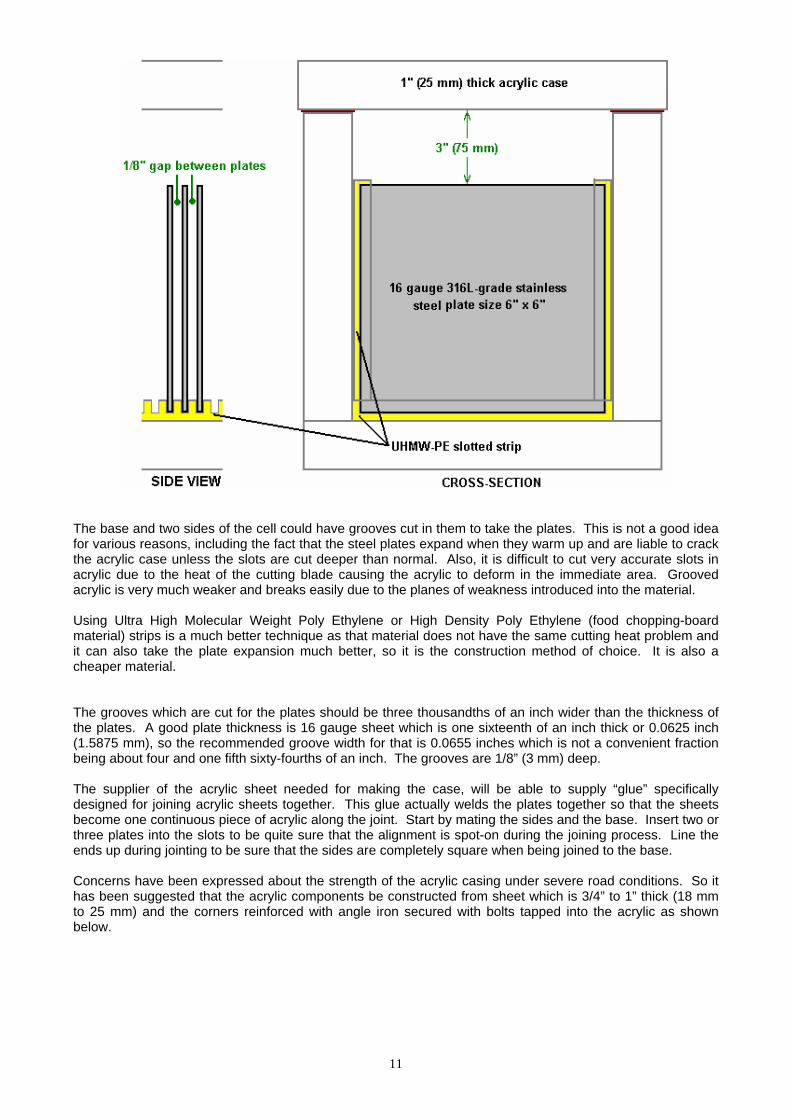
The base and two sides of the cell could have grooves cut in them to take the plates. This is not a good idea for various reasons, including the fact that the steel plates expand when they warm up and are liable to crack the acrylic case unless the slots are cut deeper than normal. Also, it is difficult to cut very accurate slots in acrylic due to the heat of the cutting blade causing the acrylic to deform in the immediate area. Grooved acrylic is very much weaker and breaks easily due to the planes of weakness introduced into the material. Using Ultra High Molecular Weight Poly Ethylene or High Density Poly Ethylene (food chopping-board material) strips is a much better technique as that material does not have the same cutting heat problem and it can also take the plate expansion much better, so it is the construction method of choice. It is also a cheaper material. The grooves which are cut for the plates should be three thousandths of an inch wider than the thickness of the plates. A good plate thickness is 16 gauge sheet which is one sixteenth of an inch thick or 0.0625 inch (1.5875 mm), so the recommended groove width for that is 0.0655 inches which is not a convenient fraction being about four and one fifth sixty-fourths of an inch. The grooves are 1/8” (3 mm) deep. The supplier of the acrylic sheet needed for making the case, will be able to supply “glue” specifically designed for joining acrylic sheets together. This glue actually welds the plates together so that the sheets become one continuous piece of acrylic along the joint. Start by mating the sides and the base. Insert two or three plates into the slots to be quite sure that the alignment is spot-on during the joining process. Line the ends up during jointing to be sure that the sides are completely square when being joined to the base. Concerns have been expressed about the strength of the acrylic casing under severe road conditions. So it has been suggested that the acrylic components be constructed from sheet which is 3/4” to 1” thick (18 mm to 25 mm) and the corners reinforced with angle iron secured with bolts tapped into the acrylic as shown below.
11
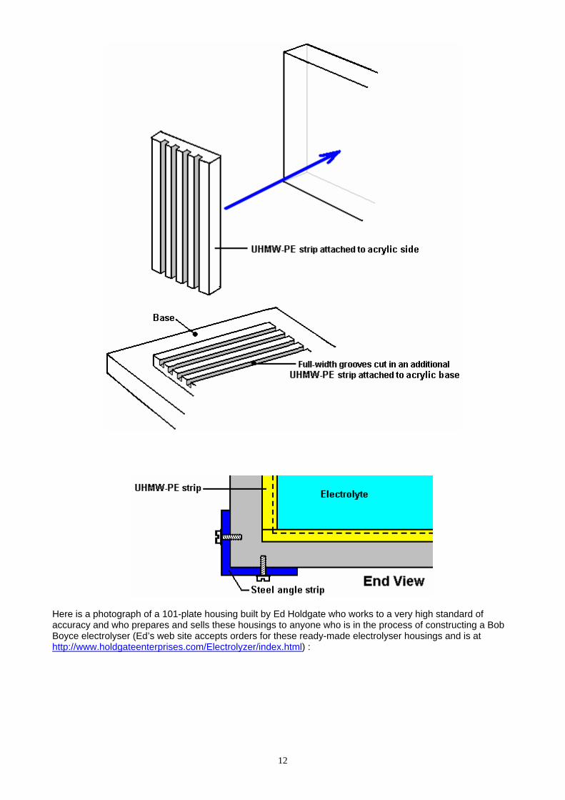
Here is a photograph of a 101-plate housing built by Ed Holdgate who works to a very high standard of accuracy and who prepares and sells these housings to anyone who is in the process of constructing a Bob Boyce electrolyser (Ed’s web site accepts orders for these ready-made electrolyser housings and is at http://www.holdgateenterprises.com/Electrolyzer/index.html) :
12
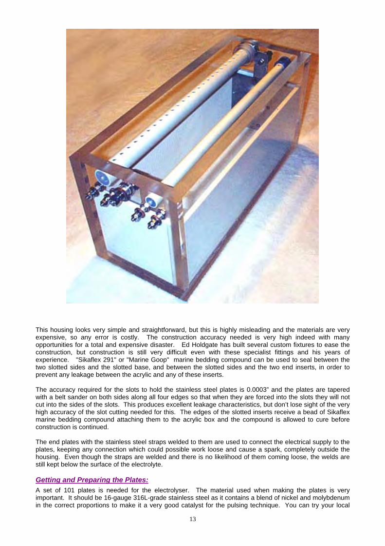
This housing looks very simple and straightforward, but this is highly misleading and the materials are very expensive, so any error is costly. The construction accuracy needed is very high indeed with many opportunities for a total and expensive disaster. Ed Holdgate has built several custom fixtures to ease the construction, but construction is still very difficult even with these specialist fittings and his years of experience. "Sikaflex 291" or "Marine Goop" marine bedding compound can be used to seal between the two slotted sides and the slotted base, and between the slotted sides and the two end inserts, in order to prevent any leakage between the acrylic and any of these inserts. The accuracy required for the slots to hold the stainless steel plates is 0.0003” and the plates are tapered with a belt sander on both sides along all four edges so that when they are forced into the slots they will not cut into the sides of the slots. This produces excellent leakage characteristics, but don’t lose sight of the very high accuracy of the slot cutting needed for this. The edges of the slotted inserts receive a bead of Sikaflex marine bedding compound attaching them to the acrylic box and the compound is allowed to cure before construction is continued. The end plates with the stainless steel straps welded to them are used to connect the electrical supply to the plates, keeping any connection which could possible work loose and cause a spark, completely outside the housing. Even though the straps are welded and there is no likelihood of them coming loose, the welds are still kept below the surface of the electrolyte. Getting and Preparing the Plates: A set of 101 plates is needed for the electrolyser. The material used when making the plates is very important. It should be 16-gauge 316L-grade stainless steel as it contains a blend of nickel and molybdenum in the correct proportions to make it a very good catalyst for the pulsing technique. You can try your local
13
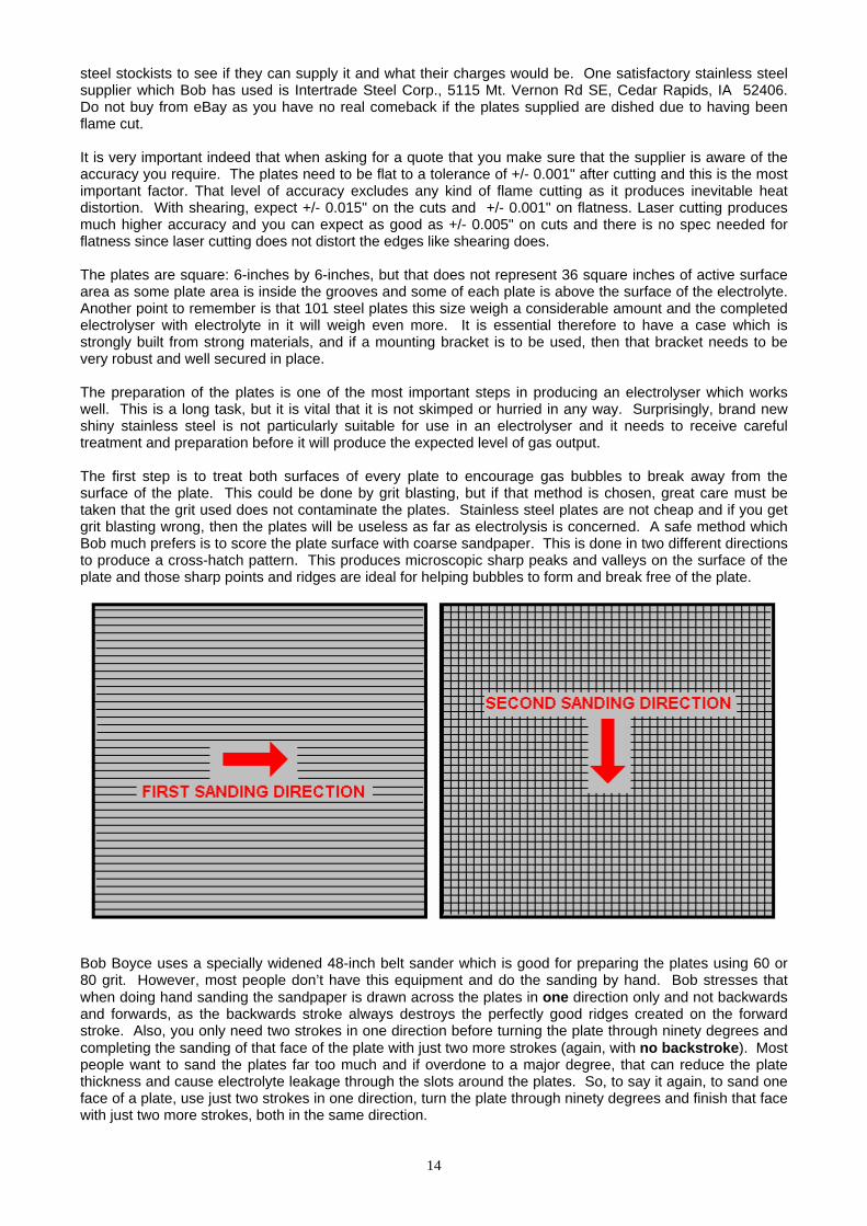
steel stockists to see if they can supply it and what their charges would be. One satisfactory stainless steel supplier which Bob has used is Intertrade Steel Corp., 5115 Mt. Vernon Rd SE, Cedar Rapids, IA 52406. Do not buy from eBay as you have no real comeback if the plates supplied are dished due to having been flame cut. It is very important indeed that when asking for a quote that you make sure that the supplier is aware of the accuracy you require. The plates need to be flat to a tolerance of +/- 0.001" after cutting and this is the most important factor. That level of accuracy excludes any kind of flame cutting as it produces inevitable heat distortion. With shearing, expect +/- 0.015" on the cuts and +/- 0.001" on flatness. Laser cutting produces much higher accuracy and you can expect as good as +/- 0.005" on cuts and there is no spec needed for flatness since laser cutting does not distort the edges like shearing does. The plates are square: 6-inches by 6-inches, but that does not represent 36 square inches of active surface area as some plate area is inside the grooves and some of each plate is above the surface of the electrolyte. Another point to remember is that 101 steel plates this size weigh a considerable amount and the completed electrolyser with electrolyte in it will weigh even more. It is essential therefore to have a case which is strongly built from strong materials, and if a mounting bracket is to be used, then that bracket needs to be very robust and well secured in place. The preparation of the plates is one of the most important steps in producing an electrolyser which works well. This is a long task, but it is vital that it is not skimped or hurried in any way. Surprisingly, brand new shiny stainless steel is not particularly suitable for use in an electrolyser and it needs to receive careful treatment and preparation before it will produce the expected level of gas output. The first step is to treat both surfaces of every plate to encourage gas bubbles to break away from the surface of the plate. This could be done by grit blasting, but if that method is chosen, great care must be taken that the grit used does not contaminate the plates. Stainless steel plates are not cheap and if you get grit blasting wrong, then the plates will be useless as far as electrolysis is concerned. A safe method which Bob much prefers is to score the plate surface with coarse sandpaper. This is done in two different directions to produce a cross-hatch pattern. This produces microscopic sharp peaks and valleys on the surface of the plate and those sharp points and ridges are ideal for helping bubbles to form and break free of the plate.
Bob Boyce uses a specially widened 48-inch belt sander which is good for preparing the plates using 60 or 80 grit. However, most people don’t have this equipment and do the sanding by hand. Bob stresses that when doing hand sanding the sandpaper is drawn across the plates in one direction only and not backwards and forwards, as the backwards stroke always destroys the perfectly good ridges created on the forward stroke. Also, you only need two strokes in one direction before turning the plate through ninety degrees and completing the sanding of that face of the plate with just two more strokes (again, with no backstroke). Most people want to sand the plates far too much and if overdone to a major degree, that can reduce the plate thickness and cause electrolyte leakage through the slots around the plates. So, to say it again, to sand one face of a plate, use just two strokes in one direction, turn the plate through ninety degrees and finish that face with just two more strokes, both in the same direction.
14

Always wear rubber gloves when handling the plates to avoid getting finger marks on the plates. Wearing these gloves is very important as the plates must be kept as clean and as grease-free as possible, ready for the next stages of their preparation. Any particles created by the sanding process should now be washed off the plates. This can be done with clean tap water (not city water though, due to all the chlorine and other chemicals added), but only use distilled water for the final rinse. A point which is often missed by people constructing electrolysers is the fact that electrolysis is not just an electrical process, but it is also a magnetic process. It is important for maximum operating efficiency that the plates are aligned magnetically. In theory, stainless steel is not magnetic, but much of the stainless steel actually supplied to builders is slightly magnetic. When the plates arrive from the supplier each plate may have random magnetic characteristics. The easiest way to deal with this situation is to try to give the plates a mild magnetic orientation. This can be done quite simply by wrapping a few turns of wire around the stack of plates and passing some brief pulses of DC current through the wire.
Obviously, the plates need to be kept in the same direction when being slotted into the case. The next step in the preparation process is to make up a weak solution of potassium hydroxide. This is done by adding small amounts of the potassium hydroxide to water held in a container. The container must not be glass as that is not a suitable material in which to mix the electrolyte. Potassium hydroxide, also called KOH or “Caustic Potash”, which can be bought from various suppliers such as: http://www.essentialdepot.com/servlet/the-13/2-lbs-Potassium-Hydroxide/Detail http://www.organic-creations.com/servlet/the-653/caustic-potassium-hydroxide-KOH/Detail http://www.aaa-chemicals.com/pohy2posa.html or http://www.nuscentscandle.com/PHFLAKES.html While Potassium hydroxide (KOH) and Sodium hydroxide (NaOH) are the very best electrolytes, they need to be treated with care. The handling for each is the same: Always store it in a sturdy air-tight container which is clearly labelled "DANGER! - Potassium Hydroxide". Keep the container in a safe place, where it can’t be reached by children, pets or people who won't take any notice of the label. If your supply of KOH is delivered in a strong plastic bag, then once you open the bag, you should transfer all its contents to sturdy, air-tight, plastic storage containers, which you can open and close without risking spilling the contents. Hardware stores sell large plastic buckets with air tight lids that can be used for this purpose. When working with dry KOH flakes or granules, wear safety goggles, rubber gloves, a long sleeved shirt, socks and long trousers. Also, don’t wear your favourite clothes when handling KOH solution as it is not the best thing to get on clothes. It is also no harm to wear a face mask which covers your mouth and nose. If you are mixing solid KOH with water, always add the KOH to the water, and not the other way round, and use a plastic container for the mixing, preferably one which has double the capacity of the finished mixture. The mixing should be done in a well-ventilated area which is not draughty as air currents can blow the dry KOH around. When mixing the electrolyte, never use warm water. The water should be cool because the chemical reaction between the water and the KOH generates a good deal of heat. If possible, place the mixing container in a larger container filled with cold water, as that will help to keep the temperature down, and if
15
16
your mixture should “boil over” it will contain the spillage. Add only a small amount of KOH at a time, stirring continuously, and if you stop stirring for any reason, put the lids back on all containers. If, in spite of all precautions, you get some KOH solution on your skin, wash it off with plenty of running cold water and apply some vinegar to the skin. Vinegar is acidic, and will help balance out the alkalinity of the KOH. You can use lemon juice if you don't have vinegar to hand - but it is always recommended to keep a bottle of vinegar handy. Plate Cleansing: Plate cleansing is always done with NaOH. Prepare a 5% to 10% (by weight) NaOH solution and let it cool down. A 5% solution ‘by weight’ is 50 grams of NaOH in 950 cc of water. A 10% solution ‘by weight’ is 100 grams of NaOH in 900 cc of water. As mentioned before, never handle the plates with your bare hands, but always use clean rubber gloves. Put the sanded and rinsed plates into the slots in the electrolyser case, keeping them all the same way round so that they remain magnetically matched. Fill the electrolyser with the NaOH solution until the plates are just covered. A voltage is now applied across the whole set of plates by attaching the leads to the outermost two plates. This voltage should be at least 2 volts per cell, but it should not exceed 2.5 volts per cell. Maintain this voltage across the set of plates for several hours at a time. The current is likely to be 4 amps or more. As this process continues, the boiling action will loosen particles from the pores and surfaces of the metal. This process produces hydroxy gas, so it is very important that the gas is not allowed to collect anywhere indoors (such as on ceilings). After several hours, disconnect the electrical supply and pour the electrolyte solution into a container. Rinse out the cells thoroughly with distilled water. Filter the dilute NaOH solution through paper towels or coffee filters to remove the particles. Pour the dilute solution back into the electrolyser and repeat this cleaning process. You may have to repeat the electrolysis and rinsing process many times before the plates stop putting out particles into the solution. If you wish, you can use a new NaOH solution each time you cleanse, but please realise that you can go through a lot of solution just in this cleaning stage if you choose to do it that way. When cleansing is finished (typically 3 days of cleansing), do a final rinse with clean distilled water. It is very important that during cleansing, during conditioning and during use, that the polarity of the electrical power is always the same. In other words, don’t swap the battery connections over as that destroys all the preparation work and requires the cleansing and conditioning processes to be carried out all over again. Plate Conditioning: Using the same concentration of solution as in cleansing, fill the electrolyser with dilute solution up to 1/2" below the tops of the plates. Do not overfill the cells. Apply about 2 volts per cell and allow the unit to run. Remember that very good ventilation is essential during this process. The cells may overflow, but this is ok for now. As water is consumed, the levels will drop. Once the cells stabilise with the liquid level at the plate tops or just below, monitor the current draw. If the current draw is fairly stable, continue with this conditioning phase continuously for two to three days, adding just enough distilled water to replace what is consumed. If the solution changes colour or develops a layer of crud on the surface of the electrolyte, then the cell stack needs more cleansing stages. Do not allow the cells to overfill and overflow at this point. After two to three days of run time, pour out the dilute KOH solution and rinse out the electrolyser thoroughly with distilled water. Cell Operation: Mix up a nearly full-strength solution of potassium hydroxide (280 grams of KOH added to 720 cc of water) as it is 20% more effective in use than is sodium hydroxide. The filling of the electrolyser depends on whether straight DC electrolysis is to be used, or resonant electrolysis is to be used. For straight DC electrolysis, fill the electrolyser to about one inch below the tops of the plates. The DC voltage applied to the electrolyser will be about 2 volts per cell or a little less, so this 100-cell electrolyser will have 180 to 200 volts applied to it. This voltage will be generated with an inverter. For resonant operation, fill the electrolyser to only half the plate height because the hydroxy gas production is so rapid that room has to be left for the gas leaving the plates. With resonant operation, about 1.5 volts per cell is used.
Troubleshooting: 1. Abnormally low current is caused by improper plate preparation or severe contamination. Take the plates
out of the electrolyser and start over again from plate preparation. 2. Abnormally high current is caused by high leakages between cells. This will require re-building or re-
sealing of the electrolyser case. 3. If current starts higher then drops off, this means that the plates are contaminated. Take the plates out of
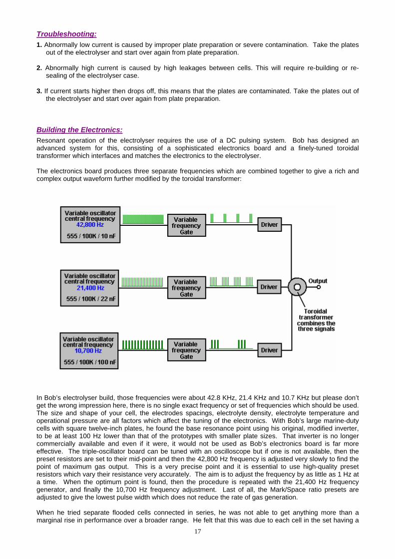
the electrolyser and start over again from plate preparation. Building the Electronics: Resonant operation of the electrolyser requires the use of a DC pulsing system. Bob has designed an advanced system for this, consisting of a sophisticated electronics board and a finely-tuned toroidal transformer which interfaces and matches the electronics to the electrolyser. The electronics board produces three separate frequencies which are combined together to give a rich and complex output waveform further modified by the toroidal transformer:
In Bob’s electrolyser build, those frequencies were about 42.8 KHz, 21.4 KHz and 10.7 KHz but please don’t get the wrong impression here, there is no single exact frequency or set of frequencies which should be used. The size and shape of your cell, the electrodes spacings, electrolyte density, electrolyte temperature and operational pressure are all factors which affect the tuning of the electronics. With Bob’s large marine-duty cells with square twelve-inch plates, he found the base resonance point using his original, modified inverter, to be at least 100 Hz lower than that of the prototypes with smaller plate sizes. That inverter is no longer commercially available and even if it were, it would not be used as Bob’s electronics board is far more effective. The triple-oscillator board can be tuned with an oscilloscope but if one is not available, then the preset resistors are set to their mid-point and then the 42,800 Hz frequency is adjusted very slowly to find the point of maximum gas output. This is a very precise point and it is essential to use high-quality preset resistors which vary their resistance very accurately. The aim is to adjust the frequency by as little as 1 Hz at a time. When the optimum point is found, then the procedure is repeated with the 21,400 Hz frequency generator, and finally the 10,700 Hz frequency adjustment. Last of all, the Mark/Space ratio presets are adjusted to give the lowest pulse width which does not reduce the rate of gas generation. When he tried separate flooded cells connected in series, he was not able to get anything more than a marginal rise in performance over a broader range. He felt that this was due to each cell in the set having a
17

18
slightly different resonant point which did not match very well with the other cells. Bob had to go to the series plate design with accurate spacing and tight tolerance on slots and plates in order to get the resonant responses to line up on all cells. Also, he found that some choices of electrolyte would not produce resonance at any frequency, though he is not sure why. Some worked well while others worked marginally, so Bob stuck with what worked the best for him - sodium hydroxide (NaOH) and potassium hydroxide (KOH). It needs to be stressed here, that every electrolyser build is slightly different from all others, even though they may have been meant to be exactly the same. There will be small differences between the plates in one electrolyser and the plates in other electrolysers. The electrolyte concentration will be slightly different, the plate preparation will be slightly different and the overall magnetic characteristics will be unique to each actual build. For that reason, the tuning of the completed electronics board and the construction of the best possible transformer to match the electronics to the electrolyser, is always different for each electrolyser built. The first step is to build the electronics control board. The methods for doing this are shown clearly in Bob’s document entitled “Boyce Electrolyser Project.pdf” which is in the “Files” section of the WorkingWatercar Yahoo forum. Bob has designed a printed circuit board to simplify the construction of the electronic drive circuitry. To see Bob’s design and to order one of these boards, you need to download and install the free “ExpressPCB” software which is located at http://www.expresspcb.com/ExpressPCBHtm/Download.htm and which can display his design files. The download is just over nine megabytes in size and contains two programs: “ExpressPCB” and “ExpressSCH”. Only the ExpressPCB program needs to be installed for you to be able to place an order for a board. The design files needed for you to be able to order the printed circuit board, are located in the “Bob Boyce Project” folder in the “Files” section of the WorkingWatercar forum. If you are not already a member of this Yahoo Group, then you need to join at http://tech.groups.yahoo.com/group/WorkingWatercar/ which is a good idea anyway as the forum members are always willing to give helpful advice. The “Bob Boyce Project” folder contains the “Boyce Electrolyser Project.pdf” document describing the construction of the electronics. You need to use the ExpressPCB program to access the “PWM3F.pcb” file which is in the “Bob Boyce Project” folder, as this small 50 Kb file contains the design and construction information needed by the manufacturer to construct the board for you. Download the PWM3F.pcb file on to your computer and double-click on it to open it with your newly installed ExpressPCB program. When the file has loaded, click on the “Layout” option at the top of the screen and then click on Click the "Compute Board Cost", enter your location, select the Two-layer Board option, then pick “MiniBoard”. Alternatively, you can get the board from The Hydrogen Garage for just US $20 at: http://stores.homestead.com/hydrogengarage/Categories.bok?category=ELECTRICAL+%2F+CIRCUITS along with other useful items like an ammeter for checking the current flow through the electrolyser. When your new printed circuit board is delivered, you will need the components to be mounted on it. Terry has set up a pre-filled order form for Digikey which you can use without having to key all the information yourself. Just click on this link: http://sales.digikey.com/scripts/ru.dll?action=pb_view&pb_glue=1014385 to order the parts which will cost about US $60 for US mainland shipping. The completed 3G board looks like this:
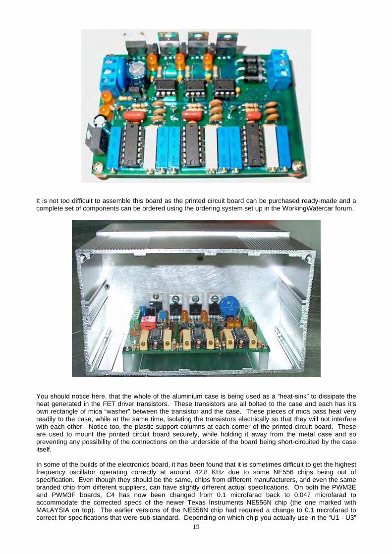
It is not too difficult to assemble this board as the printed circuit board can be purchased ready-made and a complete set of components can be ordered using the ordering system set up in the WorkingWatercar forum.
You should notice here, that the whole of the aluminium case is being used as a “heat-sink” to dissipate the heat generated in the FET driver transistors. These transistors are all bolted to the case and each has it’s own rectangle of mica “washer” between the transistor and the case. These pieces of mica pass heat very readily to the case, while at the same time, isolating the transistors electrically so that they will not interfere with each other. Notice too, the plastic support columns at each corner of the printed circuit board. These are used to mount the printed circuit board securely, while holding it away from the metal case and so preventing any possibility of the connections on the underside of the board being short-circuited by the case itself. In some of the builds of the electronics board, it has been found that it is sometimes difficult to get the highest frequency oscillator operating correctly at around 42.8 KHz due to some NE556 chips being out of specification. Even though they should be the same, chips from different manufacturers, and even the same branded chip from different suppliers, can have slightly different actual specifications. On both the PWM3E and PWM3F boards, C4 has now been changed from 0.1 microfarad back to 0.047 microfarad to accommodate the corrected specs of the newer Texas Instruments NE556N chip (the one marked with MALAYSIA on top). The earlier versions of the NE556N chip had required a change to 0.1 microfarad to correct for specifications that were sub-standard. Depending on which chip you actually use in the “U1 - U3”
19

20
board positions, you may have to adjust the value of C1, C3, and C4 to compensate for variations from the original 556 chip specification, or adjust some of the other timing component tolerances. The TAIWAN and other marked Texas Instruments chips will still work ok in the “U2” and “U3” locations, but there has been a big issue sourcing chips that will reach 43 kHz in the “U1” location. The MALAYSIA chips tested so far have been satisfactory.
Setting up the completed board: Jumper J1: If this is short-circuited it disables all three Pulse-Width Modulators, for oscillator outputs only. Jumper J2: If this is short-circuited it connects the MOSFET Gate Supply TB3 to +DC for a single supply. Jumper J3: If this is short-circuited it connects the MOSFET Source to -DC for a common ground. Jumper J4: If this is short-circuited it enables the input of the Auxiliary TTL Inputs 1, 2 and 3. This is a
convenient test point for measuring the outputs of each of the three signal generator stages. To enable the auxiliary inputs, the on-board generators must be disabled with SW1 switches 1, 2 and 3 as shown here:
Switch SW1: switching 1 on disables the Pulse-Width Modulation of oscillator 1 switching 2 on disables the Pulse-Width Modulation of oscillator 2 switching 3 on disables the Pulse-Width Modulation of oscillator 3 switching 4 on disables the Pulse-Width Modulation of all three oscillators
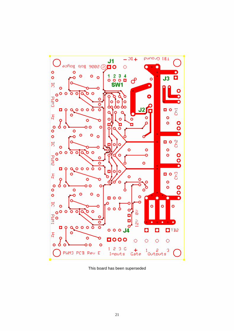
This board has been superseded
21
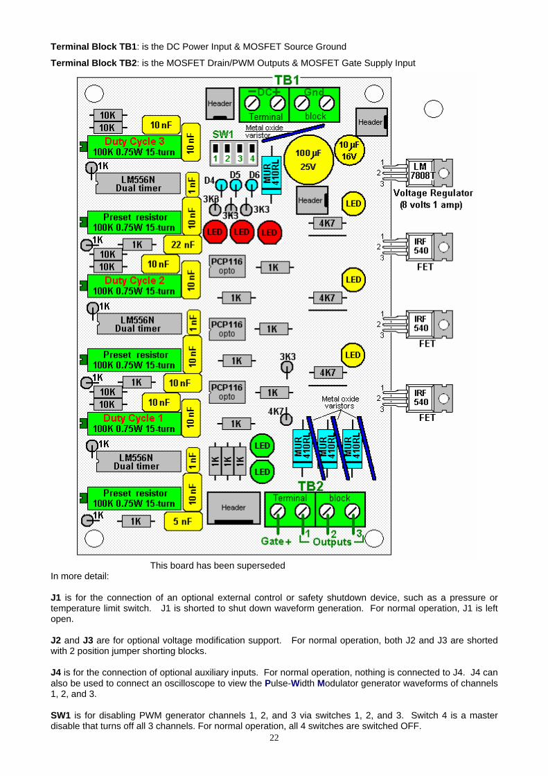
Terminal Block TB1: is the DC Power Input & MOSFET Source Ground
Terminal Block TB2: is the MOSFET Drain/PWM Outputs & MOSFET Gate Supply Input
This board has been superseded In more detail: J1 is for the connection of an optional external control or safety shutdown device, such as a pressure or temperature limit switch. J1 is shorted to shut down waveform generation. For normal operation, J1 is left open. J2 and J3 are for optional voltage modification support. For normal operation, both J2 and J3 are shorted with 2 position jumper shorting blocks. J4 is for the connection of optional auxiliary inputs. For normal operation, nothing is connected to J4. J4 can also be used to connect an oscilloscope to view the Pulse-Width Modulator generator waveforms of channels 1, 2, and 3.
22
SW1 is for disabling PWM generator channels 1, 2, and 3 via switches 1, 2, and 3. Switch 4 is a master disable that turns off all 3 channels. For normal operation, all 4 switches are switched OFF.
23
Terminal Block TB1 has 4 connections as follows; 1. DC Input + is connected to the 13.8 V DC power supply positive connection via a 2-amp fuse or circuit
breaker. 2. DC Input - is connected to the 13.8 V DC power supply negative connection. If a shorting plug is installed
at J3, this wire is optional. 3. and 4. Ground is connected to the 13.8 V DC power supply negative connection via heavy gauge wire.
There are two wire connection terminals available so that two equal length wires may be used to reduce wire resistance losses.
Terminal BlockTB2 has 4 connections which are connected as follows: Gate + is not normally connected when a shorting plug is installed at jumper J2. Output 1 is connected to the “cold” side of primary 1 of the toroidal transformer. Output 2 is connected to the “cold” side of primary 2 of the toroidal transformer. Output 3 is connected to the “cold” side of primary 3 of the toroidal transformer. The “hot” sides of primaries 1, 2, and 3 are brought together, and connected to the 13.8 V DC power supply positive connection via heavy-gauge wire and a 60-amp fuse or DC circuit-breaker. Note: These fuses are for short circuit protection, and are not an indication of system power consumption. Testing the completed board: Do NOT connect the PWM3F outputs to a powered transformer until after the unit tests show it to be fully functional. You may pull the 60-amp fuse out, or trip the DC circuit-breaker, while testing and tuning. Power up the PWM3F board and check the indicator LEDs for proper operation: LED 1 - the Channel 1 output - should be lit in normal operation, off if disabled. LED 2 - the Channel 2 output - should be lit in normal operation, off if disabled. LED 3 - the Channel 3 output - should be lit in normal operation, off if disabled. LED 4 - the PWM channel 1 disable - should be off in normal operation, on if disabled. LED 5 - the PWM channel 2 disable - should be off in normal operation, on if disabled. LED 6 - the PWM channel 3 disable - should be off in normal operation, on if disabled. LED 7 - the 12 volt supply - should be lit in normal operation, off when powered down. LED 8 - the 8 volt supply - should be lit when the power is connected and off when powered down. If all indicators check out, then start the tuning procedure. If everything checks out ok except the output indicators, then try tuning first then test again. Failures may indicate component or soldering problems. Tuning the board: Adjust all 3 of the "DC" marked (Duty Cycle) potentiometers (R25, R27, R29) fully clockwise, for minimum pulse width. Connect a frequency counter or oscilloscope to Jumper J4 pin 1 (Aux Input 3) and adjust the channel 3 "Hz" marked potentiometer (R28) for a reading of 10.7 KHz. Connect a frequency counter or oscilloscope to Jumper J4 pin 2 (Aux Input 2) and adjust the channel 2 "Hz" marked potentiometer (R26) for a reading of 21.4 KHz. Connect a frequency counter or oscilloscope to Jumper J4 pin 3 (Aux Input 1) and adjust the channel 1 "Hz" marked potentiometer (R24) for a reading of 42.8 KHz.
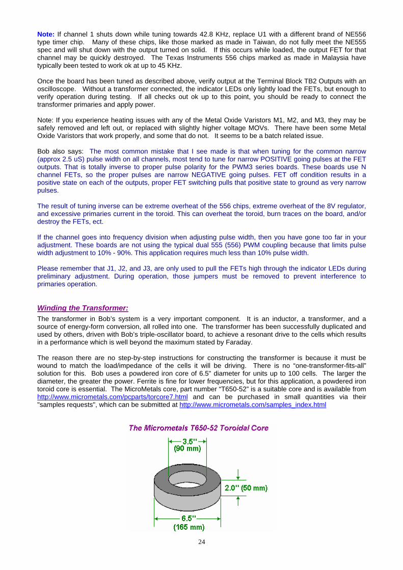
Note: If channel 1 shuts down while tuning towards 42.8 KHz, replace U1 with a different brand of NE556 type timer chip. Many of these chips, like those marked as made in Taiwan, do not fully meet the NE555 spec and will shut down with the output turned on solid. If this occurs while loaded, the output FET for that channel may be quickly destroyed. The Texas Instruments 556 chips marked as made in Malaysia have typically been tested to work ok at up to 45 KHz. Once the board has been tuned as described above, verify output at the Terminal Block TB2 Outputs with an oscilloscope. Without a transformer connected, the indicator LEDs only lightly load the FETs, but enough to verify operation during testing. If all checks out ok up to this point, you should be ready to connect the transformer primaries and apply power. Note: If you experience heating issues with any of the Metal Oxide Varistors M1, M2, and M3, they may be safely removed and left out, or replaced with slightly higher voltage MOVs. There have been some Metal Oxide Varistors that work properly, and some that do not. It seems to be a batch related issue. Bob also says: The most common mistake that I see made is that when tuning for the common narrow (approx 2.5 uS) pulse width on all channels, most tend to tune for narrow POSITIVE going pulses at the FET outputs. That is totally inverse to proper pulse polarity for the PWM3 series boards. These boards use N channel FETs, so the proper pulses are narrow NEGATIVE going pulses. FET off condition results in a positive state on each of the outputs, proper FET switching pulls that positive state to ground as very narrow pulses. The result of tuning inverse can be extreme overheat of the 556 chips, extreme overheat of the 8V regulator, and excessive primaries current in the toroid. This can overheat the toroid, burn traces on the board, and/or destroy the FETs, ect. If the channel goes into frequency division when adjusting pulse width, then you have gone too far in your adjustment. These boards are not using the typical dual 555 (556) PWM coupling because that limits pulse width adjustment to 10% - 90%. This application requires much less than 10% pulse width. Please remember that J1, J2, and J3, are only used to pull the FETs high through the indicator LEDs during preliminary adjustment. During operation, those jumpers must be removed to prevent interference to primaries operation. Winding the Transformer: The transformer in Bob’s system is a very important component. It is an inductor, a transformer, and a source of energy-form conversion, all rolled into one. The transformer has been successfully duplicated and used by others, driven with Bob’s triple-oscillator board, to achieve a resonant drive to the cells which results in a performance which is well beyond the maximum stated by Faraday. The reason there are no step-by-step instructions for constructing the transformer is because it must be wound to match the load/impedance of the cells it will be driving. There is no “one-transformer-fits-all” solution for this. Bob uses a powdered iron core of 6.5" diameter for units up to 100 cells. The larger the diameter, the greater the power. Ferrite is fine for lower frequencies, but for this application, a powdered iron toroid core is essential. The MicroMetals core, part number “T650-52” is a suitable core and is available from http://www.micrometals.com/pcparts/torcore7.html and can be purchased in small quantities via their "samples requests", which can be submitted at http://www.micrometals.com/samples_index.html
24

The primary of the transformer is 3-phase, while the secondary is single-phase. As most current flows along the outside of wires rather than through the middle of the wire, the choice and size of the wire chosen to wind the transformer is most important. Bob uses solid teflon-covered silver-plated copper wire. It is very important that this wire is solid core and not stranded as stranded wire does not work here (due to the generation of inter-strand, phase-differential induced eddy currents). At this time, a supplier of this wire is http://www.apexjr.com. Before any winding is done, the toroid is given a layer of tape. And the materials to be used are collected together, namely, the tape, the wire, the beeswax and the heat gun:
Of paramount importance with the toroid is that unlike traditional transformer design, the secondary is wound first, and the windings must be evenly spaced where they fan out from the center of the core. This means even though they are tightly packed right up against one another at the center hole, they must not be wound so that they bunch up and gap open around the periphery. Mistakes here will cause field errors that will lower the overall efficiency.
25
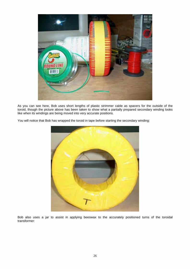
As you can see here, Bob uses short lengths of plastic strimmer cable as spacers for the outside of the toroid, though the picture above has been taken to show what a partially prepared secondary winding looks like when its windings are being moved into very accurate positions. You will notice that Bob has wrapped the toroid in tape before starting the secondary winding:
Bob also uses a jar to assist in applying beeswax to the accurately positioned turns of the toroidal transformer:
26
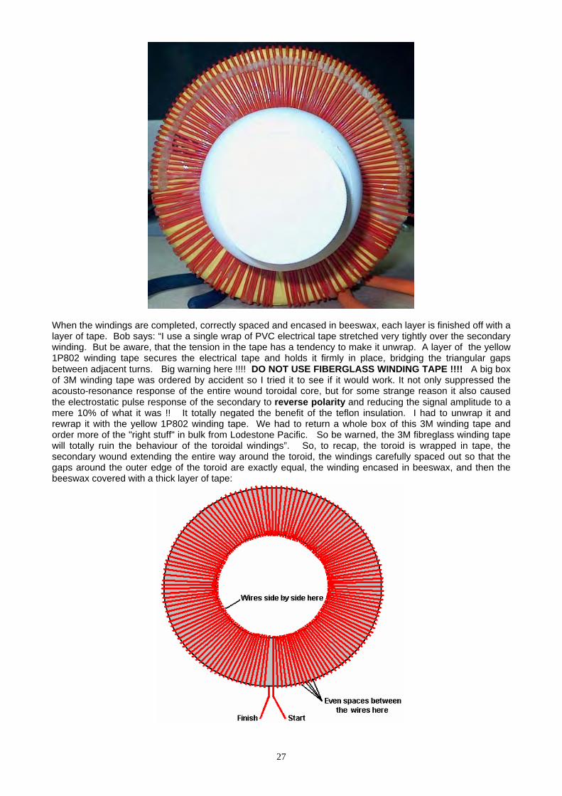
When the windings are completed, correctly spaced and encased in beeswax, each layer is finished off with a layer of tape. Bob says: “I use a single wrap of PVC electrical tape stretched very tightly over the secondary winding. But be aware, that the tension in the tape has a tendency to make it unwrap. A layer of the yellow 1P802 winding tape secures the electrical tape and holds it firmly in place, bridging the triangular gaps between adjacent turns. Big warning here !!!! DO NOT USE FIBERGLASS WINDING TAPE !!!! A big box of 3M winding tape was ordered by accident so I tried it to see if it would work. It not only suppressed the acousto-resonance response of the entire wound toroidal core, but for some strange reason it also caused the electrostatic pulse response of the secondary to reverse polarity and reducing the signal amplitude to a mere 10% of what it was !! It totally negated the benefit of the teflon insulation. I had to unwrap it and rewrap it with the yellow 1P802 winding tape. We had to return a whole box of this 3M winding tape and order more of the "right stuff" in bulk from Lodestone Pacific. So be warned, the 3M fibreglass winding tape will totally ruin the behaviour of the toroidal windings”. So, to recap, the toroid is wrapped in tape, the secondary wound extending the entire way around the toroid, the windings carefully spaced out so that the gaps around the outer edge of the toroid are exactly equal, the winding encased in beeswax, and then the beeswax covered with a thick layer of tape:
27

For the great majority of systems, the secondary winding is a tightly wound, single layer, full-fill wrap of 16 gauge, single-core, silver-plated, teflon-insulated copper wire. There will be about 133 turns in this winding, though it can vary from 127 to 147 turns due to manufacturing tolerances in the insulation. This will need a wire length of about 100 feet, and the whole of the toroid is covered by this ‘secondary’ winding. Count the exact number of turns in your actual winding and make a note of it. This secondary winding is held in place with melted beeswax, and when that has hardened, the winding is then wrapped tightly with a good quality tape. This makes a good base for the primary windings which will be wound on top of the tape layer.
Please note that every winding starts by passing over the toroid, proceeds in a counter-clockwise direction, and finishes by passing under the toroid. Every winding is created in this way and the quality of workmanship is very important indeed when making these windings. Each winding needs to be tight and positioned exactly with turns touching each other in the centre of the toroid and positioned on the outer edge with exactly equal spaces between each turn. Your construction work has to be better than that of a commercial supplier and needs to reach the quality demanded by the military, which would cost thousands of dollars for each toroid if it were to be made up for you by professionals. The three primaries need to be wound on top of the tape wrapping which covers the secondary winding. These three windings are spaced out equally around the toroid, that is, at 120 degree centres and the leads of the secondary winding exit through the gap between two of the primary windings and not in the middle of a secondary winding. The primary windings are held in place with beeswax, and then tightly taped. The primaries may need more than a single layer, and they are wound with the same direction of winds as the secondary, and the same care for even winding spacing as the secondary needed. Tape the entire core well with tightly-stretched PVC electrical tape after winding, to ensure that the primary windings do not move and then add an outer layer of winding tape. Bob uses the 1P802YE type on 3" rolls, both the 1" and 2" widths from: http://www.lodestonepacific.com/distrib/pdfs/tape/1p802.pdf This is where the generic information ends. The exact details of the primary windings must be determined from the operational characteristics of the cells. This means that you must build, cleanse and condition your cells prior to making the operational measurements. This is done as follows: After full plate cleansing as described earlier, condition the plates until the cell stack reaches at least 150% but ideally 200% or more of Faraday’s maximum power efficiency (2.34 Watt-Hours per Litre per Hour). Then, allow the cell stack to cool to room temperature. The cell stack is then powered up with a variable-voltage power supply and the voltage adjusted until the cell current is exactly 2 amps. Write down the voltage needed to give this 2 amp current flow, and do it promptly before the cell starts to warm up again. The objective here is to have the complex waveform generated by the electronics, produce voltages of about 25% of this measured voltage, so divide your measured voltage by four. The output from the electronics board is about 12.5 volts, so divide again by 12.5 to get the turns-ratio for the toroidal transformer. This is normally in the range of 3.0 to 3.5 and that means that the secondary winding needs to have that times as many turns in it as each primary winding does.
28

For example, (and example only) say your measured voltage happens to be 155 volts. Then the turns ratio would be 155 divided by 4 which is 38.75, and then divide that by 12.5 which gives 3.1 which is the turns ratio. If your secondary winding has, say, 134 turns in it, then the number of turns in each of the three primary windings would be 134 / 3.1 which is 43.23 turns. Round this upwards to give 44 turns. If the number of turns which you use is off by one turn, then the tuning of the electronics board can compensate for it. If the number of primary turns is off by two turns, then it is possible that you might just be able to compensate for the error by tuning the board, but it is unlikely that you will. If the number of turns is three or more away from the optimum number calculated, then the impedance of the primary windings will be too far out for the board to tune it. Normally, the diameter of the wire used in the primaries will be greater than that of the secondary because it will be driven by a much lower voltage and so will need a much higher current, but that is not the case here. Now that you have cleansed and conditioned the plates in your electrolyser, power up your inverter with your vehicle engine running at 2000 rpm or so, and measure the DC current taken by the inverter. This is the level of current which the primary windings have to carry, so the wire size can be selected from this measurement. Each primary winding is pulsed, so it is not carrying current all of the time, also, the final primary current is the sum of the three pulsing signals, so a reduction can be allowed for that. While the wire diameter for the primary windings of each toroidal transformer need to be calculated separately, a common diameter turns out to be AWG #20 (21 SWG). The wire length for the primaries will be greater per turn as the turns are now being made over the secondary winding. Forty-eight turns of #20 wire are likely to require at least thirty-five feet and that is for each of the three windings, assuming that all turns can be laid flat side-by-side. If it is necessary to make each a two-layer winding, then the wire length will increase further. If you would like a 360 degree template for marking the positions of the primary windings, then there is one available at http://www.thegsresources.com/files/degree_wheel.pdf
Power Limits: At the present time, the largest available iron-powder toroid commercially available is the Micrometals 6.5" unit. This sets the upper power limit for a Bob Boyce design electrolyser at 32 square inches of plate area. Bob’s present design uses six inch square plates, but the electrolyte level is maintained at just three inches and some area is effectively lost where the plates enter the walls and base of the housing. This 101-plate unit, when built with precision and conditioned and tuned correctly, can generate 50 lpm continuously and short bursts of up to 100 lpm. That is about one litre per minute of hydroxy gas per cell. This should be sufficient to run an internal combustion engine with a one litre engine capacity, but engines vary so much, that there can be no rule of thumb for the gas production rate needed for a given engine size.
29
The optimum operating voltage for his 101-plate electrolyser has been established by Bob as being 1.5 volts per cell. However, the power limitation of the 6.5 inch toroid does not prevent the voltage being raised. So, if we opt for using a 220 volt inverter rather than the 110 volt one already described, then the number of cells can be doubled. This extends the case from about twenty inches in length to around forty inches. This might be suitable for use with vehicles up to two litre engine capacity and the unit can be located on the flatbed of a truck or the boot (trunk) of a car or beside a generator if it is being used to power an electrical generator.
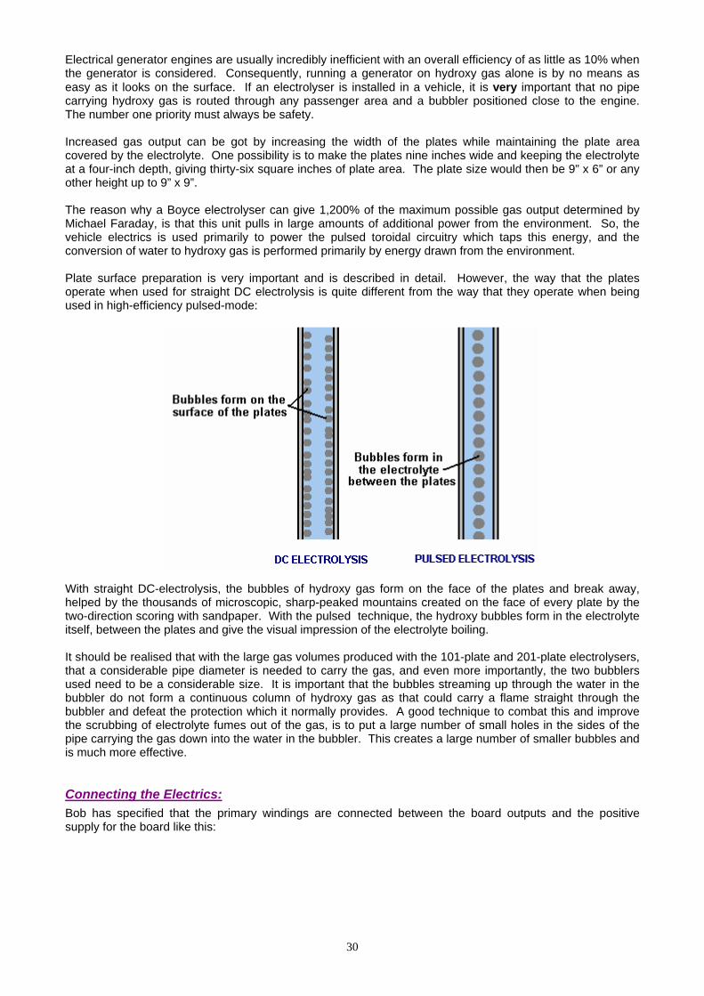
Electrical generator engines are usually incredibly inefficient with an overall efficiency of as little as 10% when the generator is considered. Consequently, running a generator on hydroxy gas alone is by no means as easy as it looks on the surface. If an electrolyser is installed in a vehicle, it is very important that no pipe carrying hydroxy gas is routed through any passenger area and a bubbler positioned close to the engine. The number one priority must always be safety. Increased gas output can be got by increasing the width of the plates while maintaining the plate area covered by the electrolyte. One possibility is to make the plates nine inches wide and keeping the electrolyte at a four-inch depth, giving thirty-six square inches of plate area. The plate size would then be 9” x 6” or any other height up to 9” x 9”. The reason why a Boyce electrolyser can give 1,200% of the maximum possible gas output determined by Michael Faraday, is that this unit pulls in large amounts of additional power from the environment. So, the vehicle electrics is used primarily to power the pulsed toroidal circuitry which taps this energy, and the conversion of water to hydroxy gas is performed primarily by energy drawn from the environment. Plate surface preparation is very important and is described in detail. However, the way that the plates operate when used for straight DC electrolysis is quite different from the way that they operate when being used in high-efficiency pulsed-mode:
With straight DC-electrolysis, the bubbles of hydroxy gas form on the face of the plates and break away, helped by the thousands of microscopic, sharp-peaked mountains created on the face of every plate by the two-direction scoring with sandpaper. With the pulsed technique, the hydroxy bubbles form in the electrolyte itself, between the plates and give the visual impression of the electrolyte boiling. It should be realised that with the large gas volumes produced with the 101-plate and 201-plate electrolysers, that a considerable pipe diameter is needed to carry the gas, and even more importantly, the two bubblers used need to be a considerable size. It is important that the bubbles streaming up through the water in the bubbler do not form a continuous column of hydroxy gas as that could carry a flame straight through the bubbler and defeat the protection which it normally provides. A good technique to combat this and improve the scrubbing of electrolyte fumes out of the gas, is to put a large number of small holes in the sides of the pipe carrying the gas down into the water in the bubbler. This creates a large number of smaller bubbles and is much more effective. Connecting the Electrics: Bob has specified that the primary windings are connected between the board outputs and the positive supply for the board like this:
30
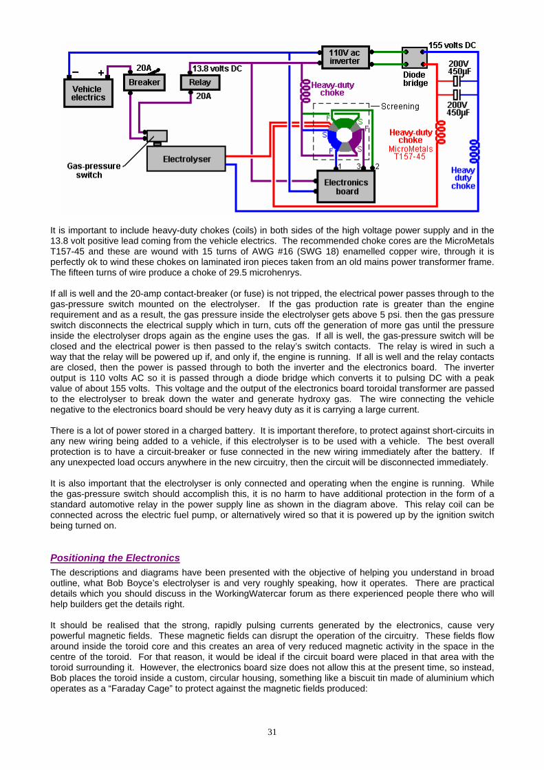
It is important to include heavy-duty chokes (coils) in both sides of the high voltage power supply and in the 13.8 volt positive lead coming from the vehicle electrics. The recommended choke cores are the MicroMetals T157-45 and these are wound with 15 turns of AWG #16 (SWG 18) enamelled copper wire, through it is perfectly ok to wind these chokes on laminated iron pieces taken from an old mains power transformer frame. The fifteen turns of wire produce a choke of 29.5 microhenrys. If all is well and the 20-amp contact-breaker (or fuse) is not tripped, the electrical power passes through to the gas-pressure switch mounted on the electrolyser. If the gas production rate is greater than the engine requirement and as a result, the gas pressure inside the electrolyser gets above 5 psi. then the gas pressure switch disconnects the electrical supply which in turn, cuts off the generation of more gas until the pressure inside the electrolyser drops again as the engine uses the gas. If all is well, the gas-pressure switch will be closed and the electrical power is then passed to the relay’s switch contacts. The relay is wired in such a way that the relay will be powered up if, and only if, the engine is running. If all is well and the relay contacts are closed, then the power is passed through to both the inverter and the electronics board. The inverter output is 110 volts AC so it is passed through a diode bridge which converts it to pulsing DC with a peak value of about 155 volts. This voltage and the output of the electronics board toroidal transformer are passed to the electrolyser to break down the water and generate hydroxy gas. The wire connecting the vehicle negative to the electronics board should be very heavy duty as it is carrying a large current. There is a lot of power stored in a charged battery. It is important therefore, to protect against short-circuits in any new wiring being added to a vehicle, if this electrolyser is to be used with a vehicle. The best overall protection is to have a circuit-breaker or fuse connected in the new wiring immediately after the battery. If any unexpected load occurs anywhere in the new circuitry, then the circuit will be disconnected immediately. It is also important that the electrolyser is only connected and operating when the engine is running. While the gas-pressure switch should accomplish this, it is no harm to have additional protection in the form of a standard automotive relay in the power supply line as shown in the diagram above. This relay coil can be connected across the electric fuel pump, or alternatively wired so that it is powered up by the ignition switch being turned on. Positioning the Electronics The descriptions and diagrams have been presented with the objective of helping you understand in broad outline, what Bob Boyce’s electrolyser is and very roughly speaking, how it operates. There are practical details which you should discuss in the WorkingWatercar forum as there experienced people there who will help builders get the details right. It should be realised that the strong, rapidly pulsing currents generated by the electronics, cause very powerful magnetic fields. These magnetic fields can disrupt the operation of the circuitry. These fields flow around inside the toroid core and this creates an area of very reduced magnetic activity in the space in the centre of the toroid. For that reason, it would be ideal if the circuit board were placed in that area with the toroid surrounding it. However, the electronics board size does not allow this at the present time, so instead, Bob places the toroid inside a custom, circular housing, something like a biscuit tin made of aluminium which operates as a “Faraday Cage” to protect against the magnetic fields produced:
31
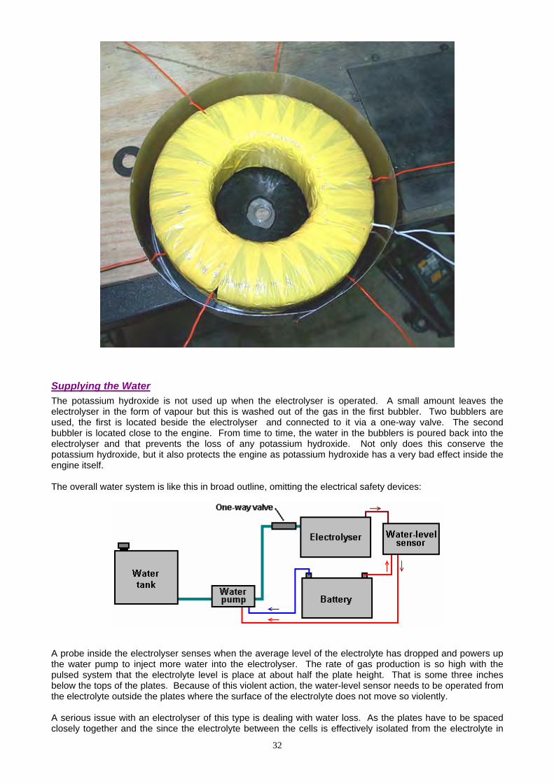
Supplying the Water The potassium hydroxide is not used up when the electrolyser is operated. A small amount leaves the electrolyser in the form of vapour but this is washed out of the gas in the first bubbler. Two bubblers are used, the first is located beside the electrolyser and connected to it via a one-way valve. The second bubbler is located close to the engine. From time to time, the water in the bubblers is poured back into the electrolyser and that prevents the loss of any potassium hydroxide. Not only does this conserve the potassium hydroxide, but it also protects the engine as potassium hydroxide has a very bad effect inside the engine itself. The overall water system is like this in broad outline, omitting the electrical safety devices:
A probe inside the electrolyser senses when the average level of the electrolyte has dropped and powers up the water pump to inject more water into the electrolyser. The rate of gas production is so high with the pulsed system that the electrolyte level is place at about half the plate height. That is some three inches below the tops of the plates. Because of this violent action, the water-level sensor needs to be operated from the electrolyte outside the plates where the surface of the electrolyte does not move so violently. A serious issue with an electrolyser of this type is dealing with water loss. As the plates have to be spaced closely together and the since the electrolyte between the cells is effectively isolated from the electrolyte in
32
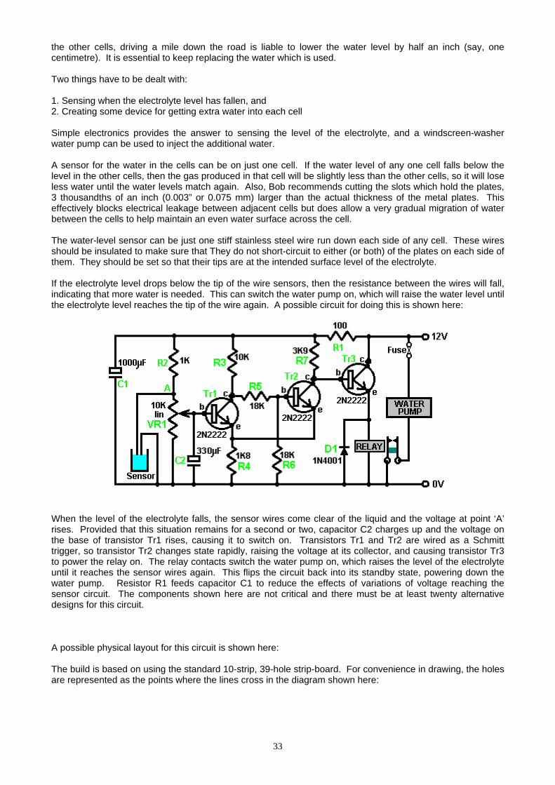
the other cells, driving a mile down the road is liable to lower the water level by half an inch (say, one centimetre). It is essential to keep replacing the water which is used. Two things have to be dealt with: 1. Sensing when the electrolyte level has fallen, and 2. Creating some device for getting extra water into each cell Simple electronics provides the answer to sensing the level of the electrolyte, and a windscreen-washer water pump can be used to inject the additional water. A sensor for the water in the cells can be on just one cell. If the water level of any one cell falls below the level in the other cells, then the gas produced in that cell will be slightly less than the other cells, so it will lose less water until the water levels match again. Also, Bob recommends cutting the slots which hold the plates, 3 thousandths of an inch (0.003” or 0.075 mm) larger than the actual thickness of the metal plates. This effectively blocks electrical leakage between adjacent cells but does allow a very gradual migration of water between the cells to help maintain an even water surface across the cell. The water-level sensor can be just one stiff stainless steel wire run down each side of any cell. These wires should be insulated to make sure that They do not short-circuit to either (or both) of the plates on each side of them. They should be set so that their tips are at the intended surface level of the electrolyte. If the electrolyte level drops below the tip of the wire sensors, then the resistance between the wires will fall, indicating that more water is needed. This can switch the water pump on, which will raise the water level until the electrolyte level reaches the tip of the wire again. A possible circuit for doing this is shown here:
When the level of the electrolyte falls, the sensor wires come clear of the liquid and the voltage at point ‘A’ rises. Provided that this situation remains for a second or two, capacitor C2 charges up and the voltage on the base of transistor Tr1 rises, causing it to switch on. Transistors Tr1 and Tr2 are wired as a Schmitt trigger, so transistor Tr2 changes state rapidly, raising the voltage at its collector, and causing transistor Tr3 to power the relay on. The relay contacts switch the water pump on, which raises the level of the electrolyte until it reaches the sensor wires again. This flips the circuit back into its standby state, powering down the water pump. Resistor R1 feeds capacitor C1 to reduce the effects of variations of voltage reaching the sensor circuit. The components shown here are not critical and there must be at least twenty alternative designs for this circuit. A possible physical layout for this circuit is shown here: The build is based on using the standard 10-strip, 39-hole strip-board. For convenience in drawing, the holes are represented as the points where the lines cross in the diagram shown here:
33
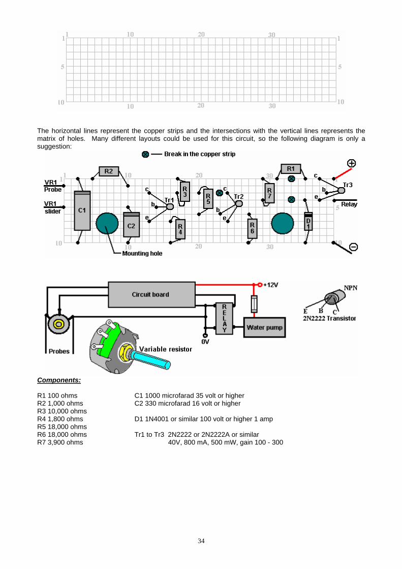
The horizontal lines represent the copper strips and the intersections with the vertical lines represents the matrix of holes. Many different layouts could be used for this circuit, so the following diagram is only a suggestion:
Components: R1 100 ohms C1 1000 microfarad 35 volt or higher R2 1,000 ohms C2 330 microfarad 16 volt or higher R3 10,000 ohms R4 1,800 ohms D1 1N4001 or similar 100 volt or higher 1 amp R5 18,000 ohms R6 18,000 ohms Tr1 to Tr3 2N2222 or 2N2222A or similar R7 3,900 ohms 40V, 800 mA, 500 mW, gain 100 - 300
34
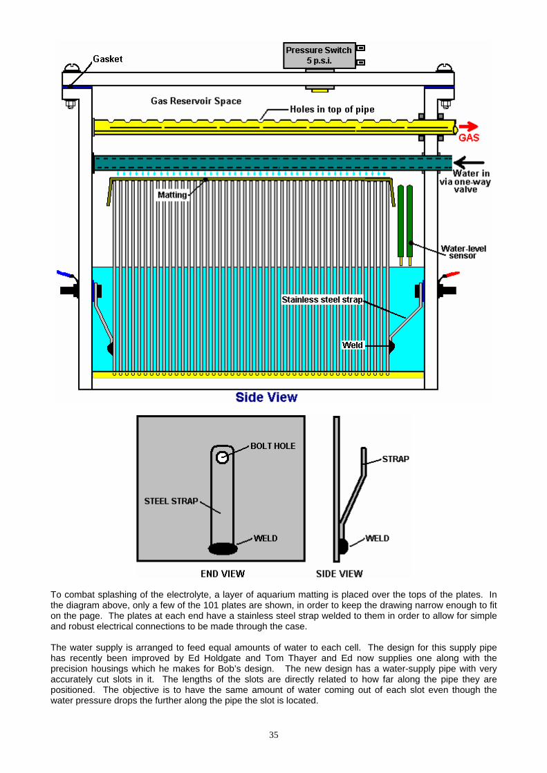
To combat splashing of the electrolyte, a layer of aquarium matting is placed over the tops of the plates. In the diagram above, only a few of the 101 plates are shown, in order to keep the drawing narrow enough to fit on the page. The plates at each end have a stainless steel strap welded to them in order to allow for simple and robust electrical connections to be made through the case. The water supply is arranged to feed equal amounts of water to each cell. The design for this supply pipe has recently been improved by Ed Holdgate and Tom Thayer and Ed now supplies one along with the precision housings which he makes for Bob’s design. The new design has a water-supply pipe with very accurately cut slots in it. The lengths of the slots are directly related to how far along the pipe they are positioned. The objective is to have the same amount of water coming out of each slot even though the water pressure drops the further along the pipe the slot is located.
35
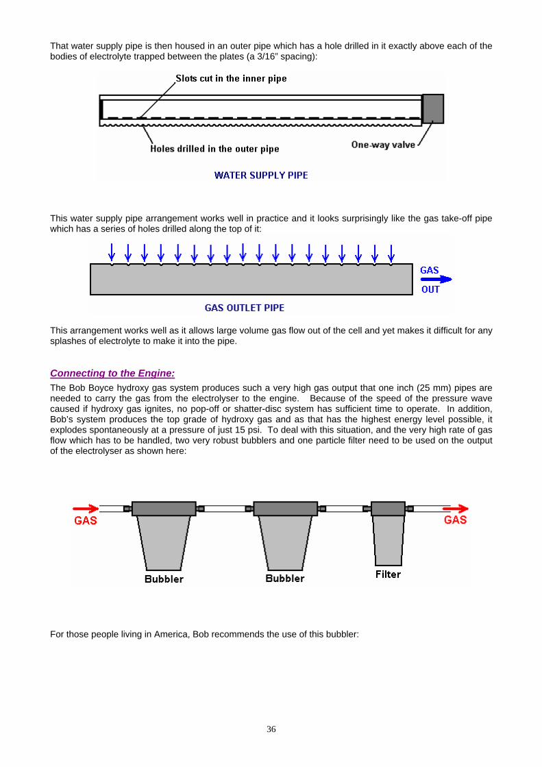
That water supply pipe is then housed in an outer pipe which has a hole drilled in it exactly above each of the bodies of electrolyte trapped between the plates (a 3/16” spacing):
This water supply pipe arrangement works well in practice and it looks surprisingly like the gas take-off pipe which has a series of holes drilled along the top of it:
This arrangement works well as it allows large volume gas flow out of the cell and yet makes it difficult for any splashes of electrolyte to make it into the pipe. Connecting to the Engine: The Bob Boyce hydroxy gas system produces such a very high gas output that one inch (25 mm) pipes are needed to carry the gas from the electrolyser to the engine. Because of the speed of the pressure wave caused if hydroxy gas ignites, no pop-off or shatter-disc system has sufficient time to operate. In addition, Bob’s system produces the top grade of hydroxy gas and as that has the highest energy level possible, it explodes spontaneously at a pressure of just 15 psi. To deal with this situation, and the very high rate of gas flow which has to be handled, two very robust bubblers and one particle filter need to be used on the output of the electrolyser as shown here:
For those people living in America, Bob recommends the use of this bubbler:
36
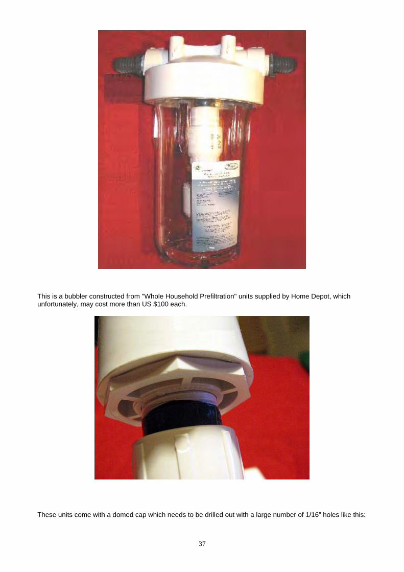
This is a bubbler constructed from "Whole Household Prefiltration" units supplied by Home Depot, which unfortunately, may cost more than US $100 each.
These units come with a domed cap which needs to be drilled out with a large number of 1/16” holes like this:
37
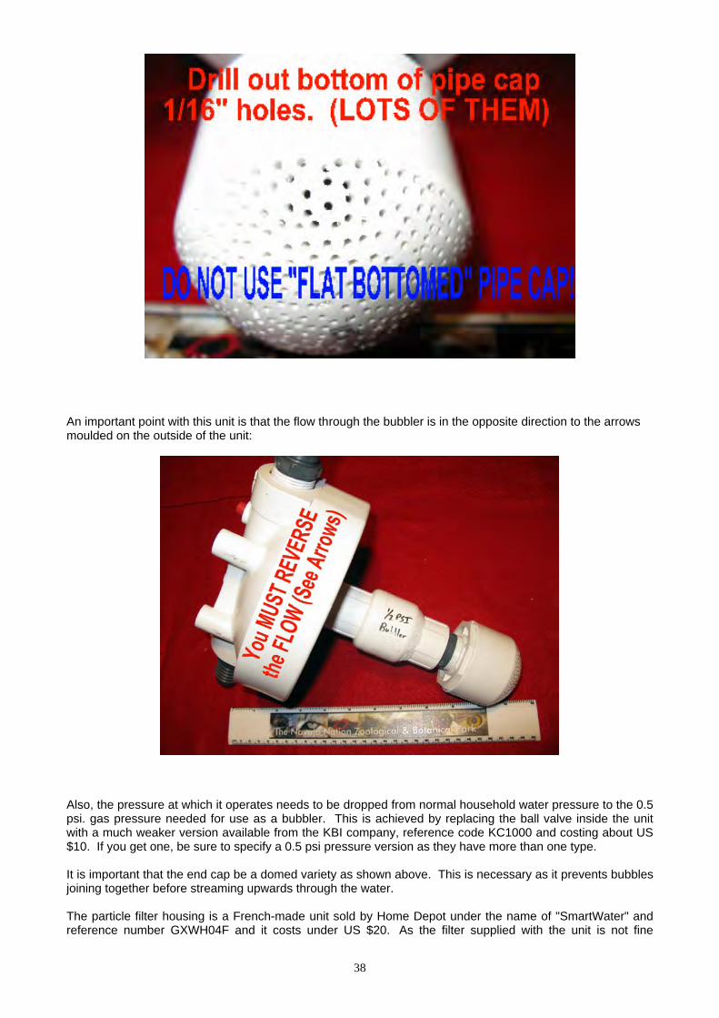
An important point with this unit is that the flow through the bubbler is in the opposite direction to the arrows moulded on the outside of the unit:
Also, the pressure at which it operates needs to be dropped from normal household water pressure to the 0.5 psi. gas pressure needed for use as a bubbler. This is achieved by replacing the ball valve inside the unit with a much weaker version available from the KBI company, reference code KC1000 and costing about US $10. If you get one, be sure to specify a 0.5 psi pressure version as they have more than one type. It is important that the end cap be a domed variety as shown above. This is necessary as it prevents bubbles joining together before streaming upwards through the water. The particle filter housing is a French-made unit sold by Home Depot under the name of "SmartWater" and reference number GXWH04F and it costs under US $20. As the filter supplied with the unit is not fine
38

enough, so a 1-micron filter needs to be bought from Ace Hardware to replace the standard 4-micron filter supplied with the filter housing. This 1-micron adapted filter also acts as a back-flash preventer:
Further building advice and general encouragement can be had from various enthusiast forums, including: http://tech.groups.yahoo.com/group/WorkingWatercar/?yguid=274961312 http://tech.groups.yahoo.com/group/Hydroxy/?yguid=274961312 and http://tech.groups.yahoo.com/group/watercar/?yguid=274961312 Practical Issues No matter which variety of electrolyser cell is used, it is essential to put a bubbler between it and the engine intake. This is to prevent any accidental ignition of the gas reaching the electrolysis cell. Also, no electrolyser should be operated or tested indoors. This is because the gas is lighter than air so any leak of gas will cause the gas to collect on the ceiling where it can cause a major explosion when triggered by the slightest spark (such as is generated when a light switch is turned on or off). Hydrogen gas escapes very easily indeed as its atoms are very, very small and can get through any tiny crack and even directly through many apparently solid materials. Testing electrolysers should be done outdoors or at the very least, in very well-ventilated locations. Using at least one bubbler is an absolutely vital safety measure. A typical bubbler looks like this:
39

Bubbler construction is very simple indeed. It can be any size or shape provided that the outlet of the entry tube has at least five inches (125 mm) of water above it. Plastic is a common choice for the material and fittings are easy to find. It is very important that good sealed joints are made where all pipes and wires enter any container which has hydroxy gas in it. This, of course, includes the bubbler. Bob Boyce’s 101-plate units produce up to 100 lpm of gas, so these need large diameter gas piping to carry that substantial volume and the bubblers need to be big as well. It is also a good idea to drill additional holes in the entry pipe from half way down below the surface of the water, in order to create a larger number of smaller bubbles The anti-slosh filling or a baffle plate in the cap is to prevent the water in the bubbler from splashing up into the exit pipe and being drawn into the engine. Various materials have been used for the filling including stainless steel wool and plastic pot scourers. The material needs to prevent, or at least minimise, any water passing through it, while at the same time allowing the gas to flow freely through it. Let me stress again, that this document does NOT recommend that you actually build any of the items of equipment discussed here. The ‘hydroxy’ gas produced by electrolysis of water is extremely dangerous, explodes instantly and cannot be stored safely, so this document is strictly for information purposes only. However, to understand the process more fully, the following details would need to be considered carefully if somebody decided to actually build one of these high-voltage series-cell devices. There is a considerable difference between a mixture of hydrogen and oxygen gases (‘hydroxy’) and petroleum (gasoline) vapour. While they both can serve as fuel for an internal combustion engine, they have considerable differences. One major difference is that hydroxy gas burns very much faster than petrol vapour. That would not be a problem if the engine was originally designed to burn hydroxy gas. However, most existing engines are arranged to operate on fossil fuels. If using hydroxy gas to improve the burn quality and improve the mpg of a vehicle, no timing adjustments are normally necessary. However, all recent cars in the USA are fitted with an Electronic Mixture Controller and if nothing is done about that, a decrease in mpg may actually occur as the Controller may start pumping more fuel into the engine when it sees a change in the quality of the exhaust. Good information on how to deal with this problem can be found at the web site http://better-mileage.com/memberadx.html which includes details of how to deal with the Controller or in the “D17.pdf” document which is part of this series of documents. If an engine is run without any fossil fuel at all, then timing adjustments need to be made. Hydrocarbon fuels have large molecules which do not burn fast enough to be efficient inside the cylinder of an engine. What happens is that for the first fraction of a second after the spark plug fires, the molecules inside the cylinder split up into much smaller particles, and then these smaller particles burn so fast that it can be described as an explosion:
40
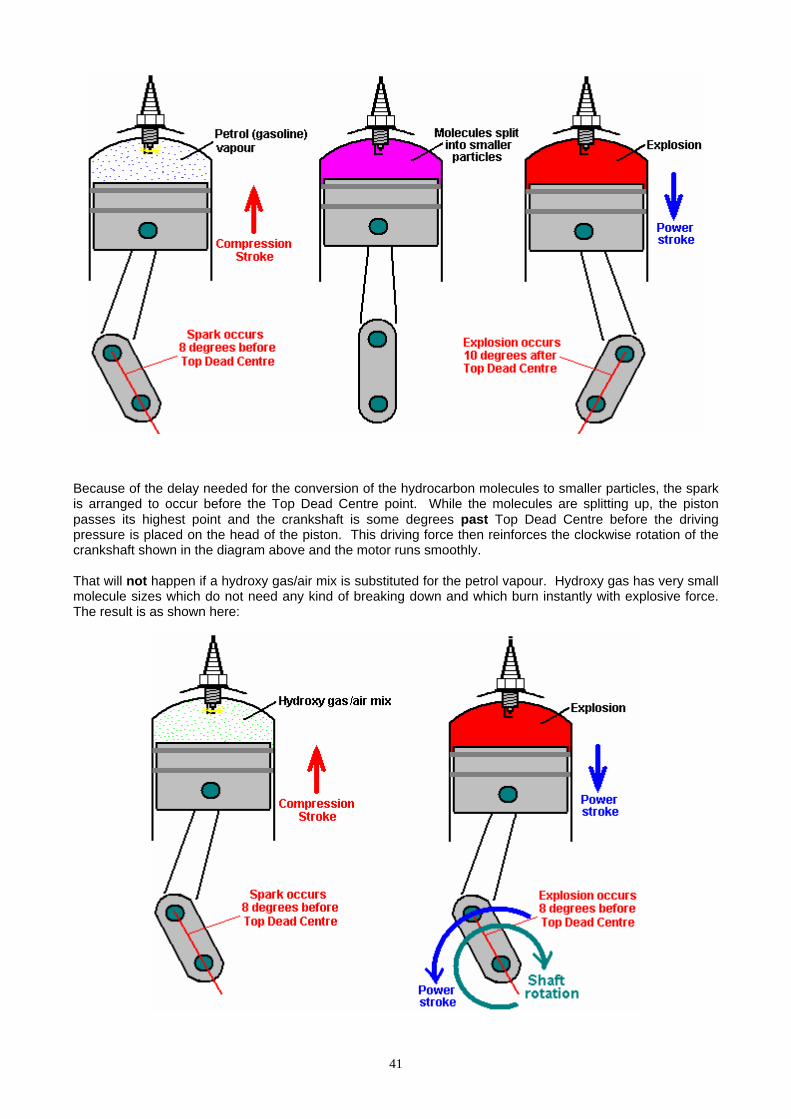
Because of the delay needed for the conversion of the hydrocarbon molecules to smaller particles, the spark is arranged to occur before the Top Dead Centre point. While the molecules are splitting up, the piston passes its highest point and the crankshaft is some degrees past Top Dead Centre before the driving pressure is placed on the head of the piston. This driving force then reinforces the clockwise rotation of the crankshaft shown in the diagram above and the motor runs smoothly. That will not happen if a hydroxy gas/air mix is substituted for the petrol vapour. Hydroxy gas has very small molecule sizes which do not need any kind of breaking down and which burn instantly with explosive force. The result is as shown here:
41

Here, the explosion is almost instantaneous and the explosion attempts to force the piston downwards. Unfortunately, the crankshaft is trying to drive the piston upwards past the Top Dead Centre (‘TDC’) point, so the explosion will not help the engine run. Instead, the explosion will stop the crankshaft rotating, overload the crankshaft and connecting rod and produce excessive pressure on the wall of the cylinder. We do not want that to happen. The solution is to delay the spark until the piston has reached the position in its rotation where we want the explosion to take place - that is, in exactly the same place as it did when using petrol as a fuel. In the example above, the spark would be retarded (delayed) from 8 degrees before TDC to 10 degrees after TDC, or 18 degrees overall. The spark is ‘retarded’ because it needs to occur later in the rotation of the crankshaft. The amount of retardation may vary from engine to engine, but with hydroxy gas, the spark must never occur before TDC and it is preferable that the crankshaft has rotated some degrees past TDC so that most of the push from the piston goes to turn the crankshaft and as little as possible in compressing the crankshaft. Diesel Engines Diesel engines do not have spark plugs and so there is no timing alterations needed with them. Any booster volume of hydroxy gas up to 80% of the cylinder contents can be added into the air entering a diesel engine and it automatically helps the mpg performance. If a really large volume of hydroxy gas is available, then the diesel engine is set to tick over on diesel and hydroxy gas is then added to rev the engine up and provide the power. The amount of hydroxy gas should not exceed four times the amount of diesel as engine overheating will occur if it does. Roy McAlister has been running internal combustion engines on hydrogen and many mixtures of hydrogen and other fuels for forty years now. He advises anybody interested in implementing a system like this, to start with a single-cylinder engine of five horsepower or less. That way, the techniques are easily learnt and experience is gained in tuning a simple engine running on the new fuel. So, let us assume that we are going to convert a small generator engine. How do we go about it? First, we obtain our supply of the new fuel. In this case, let us assume that we will produce hydroxy gas using a multi-cell high-voltage series electrolyser as described earlier. This unit has an electrical cut-off operated by a pressure switch which operates at say, five pounds per square inch. Assuming that the electrolyser is capable of producing a sufficient volume of gas, this is roughly equivalent to a hydrogen bottle with its pressure regulators. In broad outline, the gas supply would look like this:
The physical connection to the engine is via a 6 mm (1/4 inch) stainless steel pipe, fitted with a standard knob-operated needle valve. The carburettor is removed altogether to allow maximum airflow into the engine, (or failing this, the throttle valve of the carburettor is opened wide and secured in that position). The stainless steel gas pipe has its diameter reduced further by the use of a nozzle with an internal diameter of 1 mm or so (1/16 inch or less), about the size of a hypodermic needle used by a vet. Hydroxy gas has very small molecules and will flow very freely through tiny openings. The nozzle tip is pushed close to the intake valve and the gas feed pipe is secured in place to ensure no movement:
42
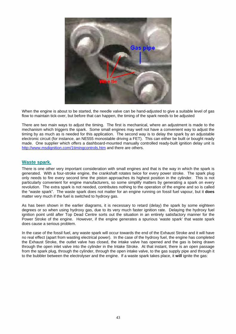
When the engine is about to be started, the needle valve can be hand-adjusted to give a suitable level of gas flow to maintain tick-over, but before that can happen, the timing of the spark needs to be adjusted There are two main ways to adjust the timing. The first is mechanical, where an adjustment is made to the mechanism which triggers the spark. Some small engines may well not have a convenient way to adjust the timing by as much as is needed for this application. The second way is to delay the spark by an adjustable electronic circuit (for instance, an NE555 monostable driving a FET). This can either be built or bought ready made. One supplier which offers a dashboard-mounted manually controlled ready-built ignition delay unit is http://www.msdignition.com/1timingcontrols.htm and there are others. Waste spark. There is one other very important consideration with small engines and that is the way in which the spark is generated. With a four-stroke engine, the crankshaft rotates twice for every power stroke. The spark plug only needs to fire every second time the piston approaches its highest position in the cylinder. This is not particularly convenient for engine manufacturers, so some simplify matters by generating a spark on every revolution. The extra spark is not needed, contributes nothing to the operation of the engine and so is called the “waste spark”. The waste spark does not matter for an engine running on fossil fuel vapour, but it does matter very much if the fuel is switched to hydroxy gas. As has been shown in the earlier diagrams, it is necessary to retard (delay) the spark by some eighteen degrees or so when using hydroxy gas, due to its very much faster ignition rate. Delaying the hydroxy fuel ignition point until after Top Dead Centre sorts out the situation in an entirely satisfactory manner for the Power Stroke of the engine. However, if the engine generates a spurious ‘waste spark’ that waste spark does cause a serious problem. In the case of the fossil fuel, any waste spark will occur towards the end of the Exhaust Stroke and it will have no real effect (apart from wasting electrical power). In the case of the hydroxy fuel, the engine has completed the Exhaust Stroke, the outlet valve has closed, the intake valve has opened and the gas is being drawn through the open inlet valve into the cylinder in the Intake Stroke. At that instant, there is an open passage from the spark plug, through the cylinder, through the open intake valve, to the gas supply pipe and through it to the bubbler between the electrolyser and the engine. If a waste spark takes place, it will ignite the gas:
43
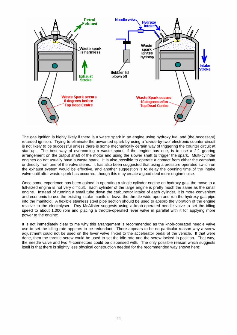
The gas ignition is highly likely if there is a waste spark in an engine using hydroxy fuel and (the necessary) retarded ignition. Trying to eliminate the unwanted spark by using a ‘divide-by-two’ electronic counter circuit is not likely to be successful unless there is some mechanically certain way of triggering the counter circuit at start-up. The best way of overcoming a waste spark, if the engine has one, is to use a 2:1 gearing arrangement on the output shaft of the motor and using the slower shaft to trigger the spark. Multi-cylinder engines do not usually have a waste spark. It is also possible to operate a contact from either the camshaft or directly from one of the valve stems. It has also been suggested that using a pressure-operated switch on the exhaust system would be effective, and another suggestion is to delay the opening time of the intake valve until after waste spark has occurred, though this may create a good deal more engine noise. Once some experience has been gained in operating a single cylinder engine on hydroxy gas, the move to a full-sized engine is not very difficult. Each cylinder of the large engine is pretty much the same as the small engine. Instead of running a small tube down the carburettor intake of each cylinder, it is more convenient and economic to use the existing intake manifold, leave the throttle wide open and run the hydroxy gas pipe into the manifold. A flexible stainless steel pipe section should be used to absorb the vibration of the engine relative to the electrolyser. Roy McAlister suggests using a knob-operated needle valve to set the idling speed to about 1,000 rpm and placing a throttle-operated lever valve in parallel with it for applying more power to the engine: It is not immediately clear to me why this arrangement is recommended as the knob-operated needle valve use to set the idling rate appears to be redundant. There appears to be no particular reason why a screw adjustment could not be used on the lever valve linked to the accelerator pedal of the vehicle. If that were done, then the throttle screw could be used to set the idle rate and the screw locked in position. That way, the needle valve and two Y-connectors could be dispensed with. The only possible reason which suggests itself is that there is slightly less physical construction needed for the recommended way shown here:
44
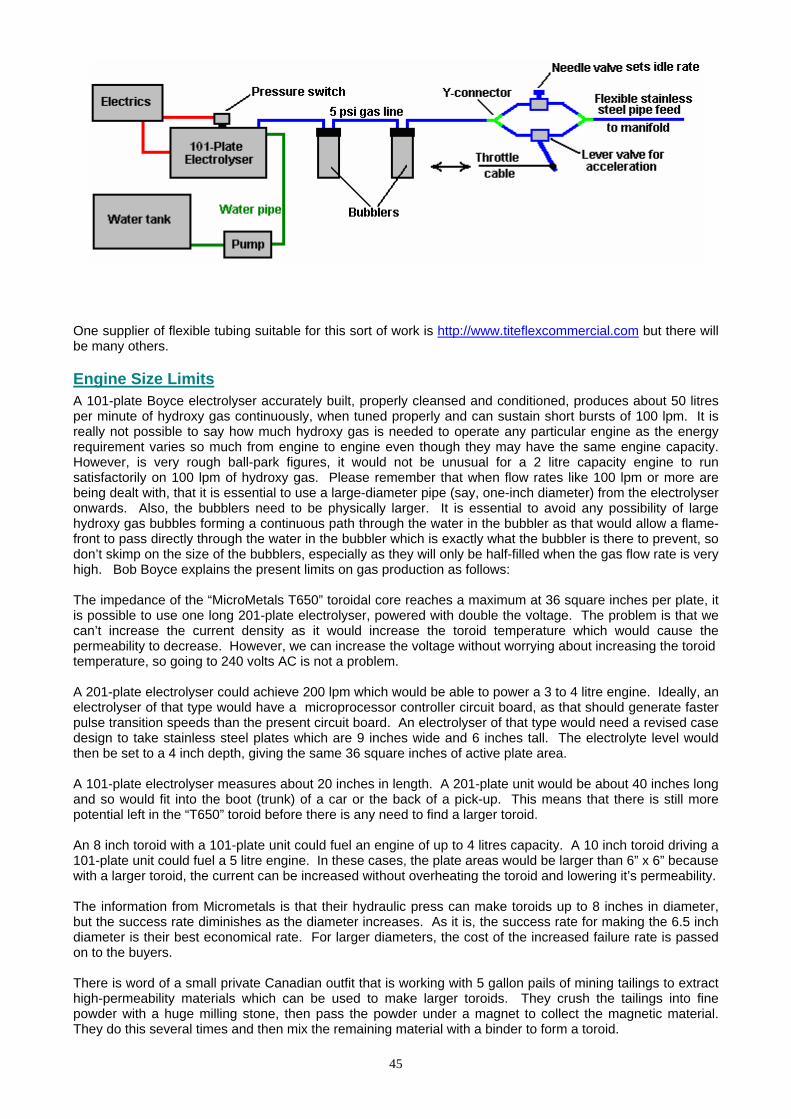
One supplier of flexible tubing suitable for this sort of work is http://www.titeflexcommercial.com but there will be many others. Engine Size Limits A 101-plate Boyce electrolyser accurately built, properly cleansed and conditioned, produces about 50 litres per minute of hydroxy gas continuously, when tuned properly and can sustain short bursts of 100 lpm. It is really not possible to say how much hydroxy gas is needed to operate any particular engine as the energy requirement varies so much from engine to engine even though they may have the same engine capacity. However, is very rough ball-park figures, it would not be unusual for a 2 litre capacity engine to run satisfactorily on 100 lpm of hydroxy gas. Please remember that when flow rates like 100 lpm or more are being dealt with, that it is essential to use a large-diameter pipe (say, one-inch diameter) from the electrolyser onwards. Also, the bubblers need to be physically larger. It is essential to avoid any possibility of large hydroxy gas bubbles forming a continuous path through the water in the bubbler as that would allow a flame-front to pass directly through the water in the bubbler which is exactly what the bubbler is there to prevent, so don’t skimp on the size of the bubblers, especially as they will only be half-filled when the gas flow rate is very high. Bob Boyce explains the present limits on gas production as follows: The impedance of the “MicroMetals T650” toroidal core reaches a maximum at 36 square inches per plate, it is possible to use one long 201-plate electrolyser, powered with double the voltage. The problem is that we can’t increase the current density as it would increase the toroid temperature which would cause the permeability to decrease. However, we can increase the voltage without worrying about increasing the toroid temperature, so going to 240 volts AC is not a problem. A 201-plate electrolyser could achieve 200 lpm which would be able to power a 3 to 4 litre engine. Ideally, an electrolyser of that type would have a microprocessor controller circuit board, as that should generate faster pulse transition speeds than the present circuit board. An electrolyser of that type would need a revised case design to take stainless steel plates which are 9 inches wide and 6 inches tall. The electrolyte level would then be set to a 4 inch depth, giving the same 36 square inches of active plate area. A 101-plate electrolyser measures about 20 inches in length. A 201-plate unit would be about 40 inches long and so would fit into the boot (trunk) of a car or the back of a pick-up. This means that there is still more potential left in the “T650” toroid before there is any need to find a larger toroid. An 8 inch toroid with a 101-plate unit could fuel an engine of up to 4 litres capacity. A 10 inch toroid driving a 101-plate unit could fuel a 5 litre engine. In these cases, the plate areas would be larger than 6” x 6” because with a larger toroid, the current can be increased without overheating the toroid and lowering it’s permeability. The information from Micrometals is that their hydraulic press can make toroids up to 8 inches in diameter, but the success rate diminishes as the diameter increases. As it is, the success rate for making the 6.5 inch diameter is their best economical rate. For larger diameters, the cost of the increased failure rate is passed on to the buyers. There is word of a small private Canadian outfit that is working with 5 gallon pails of mining tailings to extract high-permeability materials which can be used to make larger toroids. They crush the tailings into fine powder with a huge milling stone, then pass the powder under a magnet to collect the magnetic material. They do this several times and then mix the remaining material with a binder to form a toroid.
45
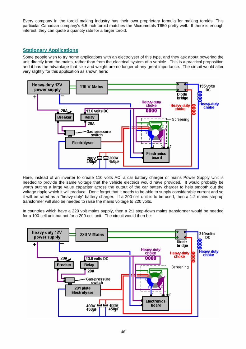
Every company in the toroid making industry has their own proprietary formula for making toroids. This particular Canadian company's 6.5 inch toroid matches the Micrometals T650 pretty well. If there is enough interest, they can quote a quantity rate for a larger toroid. Stationary Applications Some people wish to try home applications with an electrolyser of this type, and they ask about powering the unit directly from the mains, rather than from the electrical system of a vehicle. This is a practical proposition and it has the advantage that size and weight are no longer of any great importance. The circuit would alter very slightly for this application as shown here:
Here, instead of an inverter to create 110 volts AC, a car battery charger or mains Power Supply Unit is needed to provide the same voltage that the vehicle electrics would have provided. It would probably be worth putting a large value capacitor across the output of the car battery charger to help smooth out the voltage ripple which it will produce. Don’t forget that it needs to be able to supply considerable current and so it will be rated as a “heavy-duty” battery charger. If a 200-cell unit is to be used, then a 1:2 mains step-up transformer will also be needed to raise the mains voltage to 220 volts. In countries which have a 220 volt mains supply, then a 2:1 step-down mains transformer would be needed for a 100-cell unit but not for a 200-cell unit. The circuit would then be:
46

47
Bob Boyce’s Experiences: Bob had an electronics business down in south Florida where he owned and sponsored a small boat-race team through his business, starting in 1988. He had a machine shop behind his business, where he did engine work. He worked on engines for other racers and a local minisub research outfit which was building surface-running drone type boats for the DEA. He delved into hydrogen research and started building small electrolysers using distilled water mixed with an electrolyte. He then resonated the plates to improve the efficiency of the units. He discovered that with the right frequencies, He was able to generate ‘monatomic’ Hydrogen and Oxygen rather than the more common ‘diatomic’ versions of these gasses. When the ‘monatomic’ gasses are burnt, they produce about four times the energy output produced by burning the more common diatomic version of these gasses. About 4% of diatomic Hydrogen in air is needed to produce the same power as petrol, while slightly less than 1% of monatomic Hydrogen in air is needed for the same power. The only drawback is that when stored at pressure, monatomic hydrogen reverts to its more common diatomic form. To avoid this, the gas must be produced on-demand and used right away. Bob used modified Liquid Petroleum carburettors on the boat engines to let them run directly on the gas produced by his electrolysers. Bob also converted an old Chrysler car with a slant six-cylinder engine to run on the hydrogen set-up and tested it in his workshop. He replaced the factory ignition with a high energy dual coil system and added an optical pickup to the crankshaft at the oil pump drive tang to allow external ignition timing adjustment. He used Bosch Platinum series spark plugs. Bob never published anything about what he was working on, and he always stated that his boats were running on hydrogen fuel, which was allowed. Many years later that he found that he had stumbled on was already discovered and known as "Browns Gas", and there were companies selling the equipment and plans to make it. Bob’s electrolyser is fairly simple to make but it requires a lot of plates made of 316 stainless steel able to withstand the more exotic electrolytes which are more efficient, a plastic box to contain the plates, 1/8" spacers to keep the rows of plates apart, the electrolyte, and an adjustable-frequency modified pseudo-sinewave inverter for the drive electronics. A total of 101 plates 6 inches square are used to give a large surface area. These have their surfaces scoured with coarse sandpaper in an "X" pattern to give a fine crosshatch grain which added fine sharp points to the surfaces. This is found to improve the efficiency of the electrolysis. The box has two threaded ports, a small one for injecting replacement distilled water, and a larger one for extracting the hydroxy gas. Under the top cover is a piece of plastic matting to prevent sloshing. It is very important to keep the electrolyte level below the tops of the plates to prevent current bypassing any cells and creating excessive water vapour. Bob places a 5 Pounds per Square Inch cut-off switch in a tee on the water injection port that shut the drive electronics down when the pressure in the unit hit 5 PSI. This allows the unit to be able to supply on demand without building up too much pressure in low-demand situations. He builds a bubbler from a large home cartridge type water-filter housing to prevent any backfire from travelling back up the gas feed pipe to the electrolyser. Without some sort of bubbler there is the risk of the electrolyser exploding if a flame front from the engine flows back to it. The copper mesh screens designed for welding gasses will not work as hydrogen has a much higher flame propagation speed which passes straight through the copper mesh. The bubbler should be placed close to the engine so as to limit the amount of recombination of the gasses from monatomic to diatomic varieties. The hydroxy gas should be fed to the vapour portion of a Liquid Petroleum Gas carburettor system. The carburettor will have to be modified for hydrogen use (different mixture rate than propane) and adjusted for best performance with the system running. Bob found that the best electrolytes to use were Sodium Hydroxide (NaOH) and Potassium Hydroxide (KOH). While Sodium Hydroxide works well and is much easier to get (‘Red Devil’ lye found in most department stores) than the slightly more efficient Potassium Hydroxide. Whatever is used, be very careful what construction materials are used. Make absolutely sure that they are compatible with the chosen electrolyte (Plexiglas acrylic sheet was what Bob used). Never use glass containers for mixing or storing Potassium Hydroxide. Bob never had the chance to drive the test Chrysler on the road with this system. Instead, he placed the rear end up on jack-stands and ran the engine under no-load conditions in drive just to test and tune the system and get an idea of how well the engine held up on the hydrogen fuel. The vehicle was run for a milometer recorded distance of one thousand miles in this set-up with the hydrolysis being fully powered by the alternator of the vehicle. With the vehicle running at idle, the drive electronics consumed approximately 4 to
48
4.3 Amps @ 13.8 V DC. With the rear wheels off of the ground, and the engine running with the vehicle speedometer registering 60 mph, the drive electronics drew approximately 10.9 to 11.6 Amps @ 13.8 V DC. The unit does not use "normal brute force" electrolysis when operating in high efficiency mode. It relies mainly on a chemical reaction that takes place between the electrolyte used and the metal plates, which is maintained by electrical energy applied and stimulated into higher efficiency by the application of multiple harmonic resonances which help to "tickle" the molecules apart. Multiple cells in series are used to lower the voltage per cell and limit the current flow in order to reduce the production of water vapour. It relies on the large surface area of the total number of cells to get the required volume of fuel vapour output. In the first prototype of this design, Bob used a custom built controller/driver which allowed a lot of adjustment so that performance could be tested using different frequencies, voltages, and waveforms individually. The result was a pattern of 3 interwoven square waves rich in harmonics that produced optimum efficiency. When Bob had the basics figured out he realised that he could just replace the custom controller/driver unit with a modified inverter (much easier than building a unit from scratch). He experimented using a 300 watt pseudo-sine wave inverter that had been modified so the base frequency could be adjusted between 700 and 800 Hz. The stepped sine wave output was fed through a bridge rectifier which turned each stepped sine wave into two positive stepped half waves. Each of these half waves had 8 steps, so a single cycle was turned into 16 steps. The resulting output, while not consisting of intermixed square waves, was still rich in harmonics, and it was much easier to adjust to the point of resonance than trying to tune 3 separate frequencies. Please note that these inverters are no longer available for purchase and that Bob’s triple oscillator board design is far superior, giving more than double the output produced by the old inverter and is definitely the board to use with Bob’s electrolyser. The frequency range can change depending on the number of steps in the pseudo-sine wave of the inverter you choose since not all inverters are created equal. The desired effect is caused by the multiple harmonic resonances in the inverter output at higher frequencies. You will know when you hit resonance by the dramatic increase in gas output. The frequency does vary a bit depending on what electrolyte is used, the concentration of the electrolyte solution, the temperature of the electrolyte, water purity, etc. Bear in mind that Bob’s electrolyser tank was large enough to hold 61 plates of 316 grade stainless steel which were 6" X 6" each, spaced 1/8" apart, to create 60 cells in series, with the 130 V DC power from the inverter, through the bridge rectifier, applied to the end plates only. That gave 4,320 square inches of surface area, plenty of surface area to produce enough fuel for a vehicle engine. The best electrolyte for efficiency was Potassium Hydroxide, and the electrolyte level must be kept below the tops of the plates to prevent any current from bypassing the plates and creating excess water vapour through heating. Distilled water was used to prevent contamination of the electrolyte which would result in reduced performance and efficiency. The unit had 316 grade stainless steel wires welded to the tops of the end plates. The other ends of the wires were welded to 316-grade stainless steel bolts which passed through holes in the ends of the container, with rubber o-ring gaskets inside and out, located above the liquid level. There was a PVC spray bar attached on the inside of the chamber to the water injection port with tiny holes drilled along its length on the underside to supply replacement water evenly to the cells when the water pump was switched on. A backflow-prevention valve on top of the tee was used to keep the gas from flowing back into the water lines. There was a mat of interwoven plastic fibres (air conditioner filter material) cut and fitted on top of the plates to help prevent sloshing. Do not use fibreglass mat, which could cause a severe reaction with some electrolytes, like Potassium Hydroxide. It is very important to understand that unless an engine is originally designed for, or later modified for, running on vapour fuel such as Liquid Petroleum Gas (natural gas), that water mist injection be added. Unless the engine has the proper valves for vapour fuel, the stock valves will not survive for extended run times on vapour fuel of any kind without additional cooling of some sort. This is an issue of valve design by the vehicle manufacturers, not something detrimental because of hydroxy gas combustion. The manufacturers want to prevent their cars from being adapted to high mileage operation without adverse effects, so they designed the valves to fail if not cooled by excess raw fossil fuel. Newer Vehicles with ECUs One important point which has not been covered in detail, is the effect of Electronic Fuel Injection systems found in newer vehicles. There is a fairly wide range of different types and designs, but basically, newer cars are fitted with an electronic computer which controls the amount of fuel injected into an engine. These systems are designed to sense the content of the exhaust gases and if the analysis indicates that the fuel/air mix is rather lean, then the computer increases the rate of fuel flow into the engine.

49
If the vehicle has been converted to run on hydroxy gas alone, then there is no problem. But, if a hydroxy booster is being used to improve the quality of the fuel burn, then the computer will work to smother any gains in performance and cleanliness, by injecting more fossil fuel to bring the exhaust gas mix back to what it has always been expecting. If nothing is done about this, then the improvements produced by using a booster unit, will be cancelled out by the vehicle’s computer. The details of how the computer works and what can be done to deal with it form a fairly lengthy piece of information, so a separate document “D17.pdf” has been produced to cover the subject. That document, along with a considerable volume of other information on free-energy systems, can be downloaded free from the http://www.free-energy-info.co.uk web site. Patrick Kelly engpjk@yahoo.co.ukwww.free-energy-info.comwww.free-energy-devices.com