a predictive reactive scheduling method for color-coating production
TRANSCRIPT
ORIGINAL ARTICLE
A predictive reactive scheduling method for color-coatingproduction in steel industry
Lixin Tang & Xianpeng Wang
Received: 6 April 2006 /Accepted: 3 August 2006 / Published online: 8 November 2006# Springer-Verlag London Limited 2006
Abstract It is a difficult but challenging task for complexsteel production to find effective schedules in a dynamicenvironment. In this paper, a predictive reactive schedulingmethod for the color-coating production in steel industry isinvestigated. In a practical production environment, theoriginally established schedules often need to be adjusteddue to some unexpected events, which will break down theproduction continuity. Reactive scheduling is, therefore,essential for the production scheduling system to maintainthe production continuity by reconciling the conflictbetween the originally established schedules and the currentproduction status of the factory. To efficiently cope withsuch unexpected events, we propose a matching-up modelwhose objective is to minimize the impact on the originallyestablished schedule and maintain its good quality. Theexperimental results on instances collected from practicalproduction data show that the proposed method can providerobust and high quality schedules under a real-timeproduction environment.
Keywords Color-coating production scheduling .
Matching-up model . Reactive scheduling
1 Introduction
Color-coating production is the last processing procedurefor coils in the cold rolling region in most iron and steel
enterprises. The objects of color-coating production sched-uling are those coils stored at a location before theproduction line and coils that will be released from theupstream production lines in predictive time. The task ofcolor-coating production scheduling is to create productionturns for these steel coils within a given time horizon sothat the productivity and product quality are maximizedwhile the production cost is minimized.
Based on the assumption that the future conditions insteel industry are static and deterministic, a predictivescheduling system for the color-coating production hasbeen developed in our previous research (Tang and Wang,unpublished technical report, 2005) and also implementedin Baosteel, the most advanced iron and steel enterprise inChina. Generally the schedules obtained by the system canbe performed successfully in practical production. Howev-er, the practical scheduling in nature is a dynamic andongoing reactive process, and consequently such schedulesmay become inapplicable due to many unexpected events,which typically include the delayed arrival of coils fromupstream production lines and the failure to meet requiredquality. Such unexpected events may cause time gaps in theoriginally established schedule and thus break down theproduction continuity. Therefore, the reactive schedulingmust be used to reconcile the conflict between the originalschedule and the current production status to maintain theproduction continuity and good quality of the originalschedule.
A great deal of effort has been spent on the research ofreactive scheduling methods. These methods proposed inpublished literatures can be classified into two maincategories [1]: dynamic scheduling and predictive reactivescheduling. Dynamic scheduling does not generate aproduction schedule and is related to the real-time control.Predictive reactive scheduling, which is a common strategy
Int J Adv Manuf Technol (2008) 35:633–645DOI 10.1007/s00170-006-0740-y
L. Tang (*) :X. WangThe Logistics Institute, Northeastern University,Shenyang 110004, Chinae-mail: [email protected]
X. Wange-mail: [email protected]

to rescheduling dynamic manufacturing systems, has twosteps: the first step establishes a production schedule usinga predictive mechanism and the second step updates theschedule in response to disruptions to minimize theirimpacts on the performance of the scheduling system. Theupdate policies can be classified into three categories [2]:periodic, event-driven, and hybrid. The periodic policyupdates the schedule periodically. An event-driven policymakes the rescheduling when specific events occur. Ahybrid policy combines the periodic and event-drivenpolicies and performs the rescheduling periodically or uponthe occurrence of specific events. The periodic and hybridpolicies have drawn special attention under rolling timehorizon approaches [3, 4].
For dynamic scheduling, many kinds of heuristic ruleshave been proposed [5]. For predictive reactive scheduling,Yamamoto and Nof [6] proposed a rescheduling methodbased on a three-phase scheme. The planning phase firstlygenerates an initial schedule, and then the control phasecompares the process of operations to the initial schedulewhenever a new operation begins or finishes. When thedifference exceeds a specified limit, the rescheduling phaseis activated to revise the initial schedule. Wu and Li [7]described rescheduling as an iterative process of three steps:the evaluation step, the solution step, and the revision step.The evaluation step evaluates the impact the disruptionsimpose on the originally established schedule. The solutionstep, which is the most difficult part of rescheduling,determines the best rescheduling solution. The revision stepupdates the existing production schedule or generates a newone. Park et al. [8] developed a knowledge-based systemnamed IOSS to revise an existing schedule in a job shop.Suh et al. [9] evaluated several ordering strategies forconstraint satisfaction reactive scheduling of hot rollingproduction in steel industry. Akturk and Gorgulu [10]proposed a hierarchical reactive scheduling approach inresponse to machine breakdowns. Sun and Xue [11]described a dynamic reactive scheduling mechanism forresponding to changes of production orders and manufac-turing resources. Ouelhadj et al. [12] used several heuristicstrategies to response to the disruptions in steel continuouscasting, and presented utility and stability measures toevaluate these strategies. Among the conclusions drawnabout the reactive scheduling, the general consensus is thatthe performance of a reactive scheduling method is quiteproblem-dependent [13].
As described above, many methods have been proposedfor reactive scheduling in the steel industry. However, thesemethods are essentially greedy heuristics, in which a timegap is repaired by selecting the fittest slab or coil from thecandidate pool to insert into it. When a time gap is repaired,the coils or slabs inserted in it will generally not beconsidered any more. Another time gap is then repaired by
selecting the fittest slab or coil from the remainingcandidate pool. This procedure continues until all timegaps are repaired. Generally the manual reschedulingmethod in most practical productions also belongs to thiskind of greedy procedure. When such a greedy method isapplied in reactive scheduling, it is clear that the followingtime gaps after the first one will become more and moredifficult to be repaired because the number of availablecandidate slabs or coils decreases as the number of repairedtime gaps increases. To avoid the disadvantage suffered bygreedy heuristics, the rescheduling method presented in thispaper for the color-coating production firstly formulates therescheduling problem as a matching-up model, which cansimultaneously repair the time gaps in a global optimalview to minimize the impact on the originally establishedschedule and maintain its good quality. The matching-upcost consists of the penalties for differences between theunavailable coil and its corresponding candidate coil. Toensure the feasibility of the solution obtained from thematching-up model, a feasibility checking and restoringprocedure using heuristic rules will be performed. At last atabu search algorithm developed in the predictive schedul-ing system will be used to improve the feasible schedule.Such a method uses the hybrid policy and only makespartial repairs to the originally established schedules. Basedon the developed intelligent scheduling system, the reactivescheduling method for color-coating production has beentested in Baosteel.
The rest of this paper is organized as follows. Section 2describes the process and the developed predictive sched-uling system of the color-coating production. The typicalunexpected events that cause unavailable coils are intro-duced in Section 3. Section 4 presents the predictivereactive scheduling method in detail. Section 5 gives thecomputational results on instances randomly generatedfrom the data collected from practical color-coatingproduction. Finally, the research presented in this paper issummarized in Section 6.
2 Production and predictive scheduling systemof color-coating
2.1 Production process of color-coating
The production process of color-coated coils is shown inFig. 1. The coils released from the hot strip mill aretransformed into thin coils in the cold mill (CM) aftereliminating the surface oxidation by pickling. Then onepart of these cold rolled coils is further processed throughthe continuous annealing line (CAL) followed by theelectro-galvanizing line (EGL), and the other part isprocessed through the continuous galvanizing line (CGL).
634 Int J Adv Manuf Technol (2008) 35:633–645
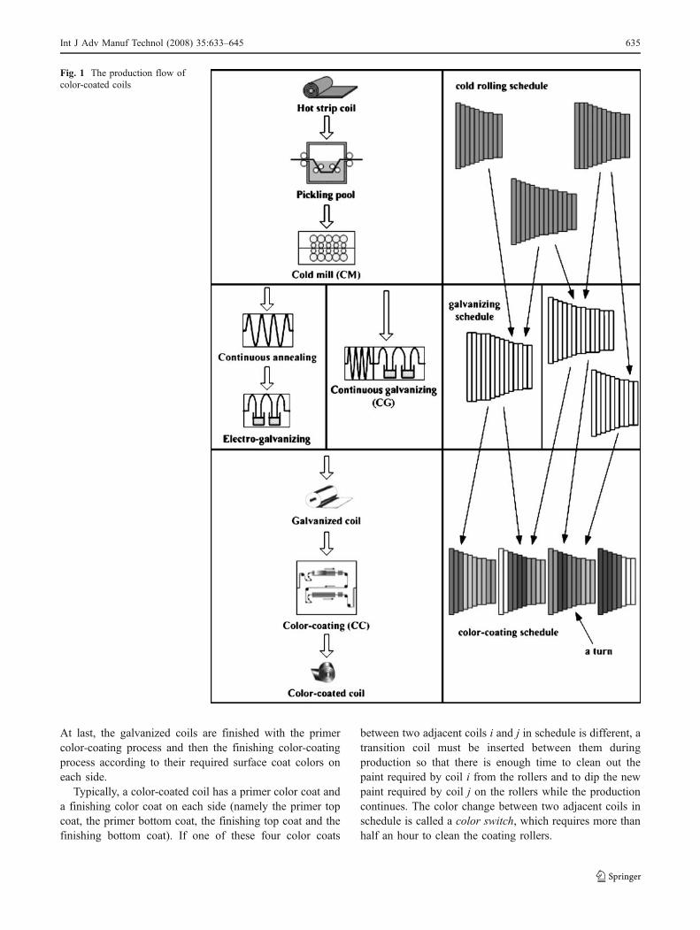
At last, the galvanized coils are finished with the primercolor-coating process and then the finishing color-coatingprocess according to their required surface coat colors oneach side.
Typically, a color-coated coil has a primer color coat anda finishing color coat on each side (namely the primer topcoat, the primer bottom coat, the finishing top coat and thefinishing bottom coat). If one of these four color coats
between two adjacent coils i and j in schedule is different, atransition coil must be inserted between them duringproduction so that there is enough time to clean out thepaint required by coil i from the rollers and to dip the newpaint required by coil j on the rollers while the productioncontinues. The color change between two adjacent coils inschedule is called a color switch, which requires more thanhalf an hour to clean the coating rollers.
Fig. 1 The production flow ofcolor-coated coils
Int J Adv Manuf Technol (2008) 35:633–645 635
2.2 Main constraints of color-coating scheduling
There are three main considerations in color-coatingscheduling: (1) productivity, (2) product quality, and (3)tardiness of orders.
Productivity means gross production per week or monthexcluding coils that cannot be delivered because of flaws orscars. Since the transition coil cannot be sold as finalproduct, the productivity will be greatly reduced if toomany color switches exist in a schedule. It is, therefore,preferred that coils having same colors be adjacent inschedule so as to reduce the color switches. Since the color-coating production line operates in a continuous way, coilsare welded one by one before processing. If the width orthickness transition of adjacent coils exceeds the permittedlimitation, the welded juncture may split during productionand consequently the transition coil will also be required tobe inserted between these two coils to reduce the transition.Therefore, it is also preferred that the width or thicknesstransition of adjacent coils should be as small as possible.
When a coil i is processing, edge marks will appear onthe rollers. If the following coil j is wider than coil i, thencolor scars caused by the edge marks will be left on coil j.Therefore, to guarantee product quality, the width of adjacentwelded coils must strictly transit from wide to narrow.
Besides these technologic constraints, it is also requiredthat the coils should be delivered before their due dates.
2.3 The predictive scheduling system for color-coatingproduction
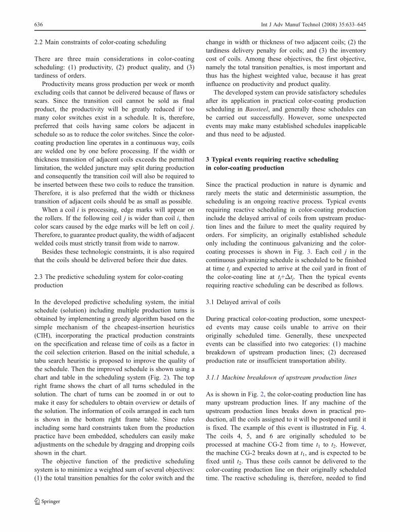
In the developed predictive scheduling system, the initialschedule (solution) including multiple production turns isobtained by implementing a greedy algorithm based on thesimple mechanism of the cheapest-insertion heuristics(CIH), incorporating the practical production constraintson the specification and release time of coils as a factor inthe coil selection criterion. Based on the initial schedule, atabu search heuristic is proposed to improve the quality ofthe schedule. Then the improved schedule is shown using achart and table in the scheduling system (Fig. 2). The topright frame shows the chart of all turns scheduled in thesolution. The chart of turns can be zoomed in or out tomake it easy for schedulers to obtain overview or details ofthe solution. The information of coils arranged in each turnis shown in the bottom right frame table. Since rulesincluding some hard constraints taken from the productionpractice have been embedded, schedulers can easily makeadjustments on the schedule by dragging and dropping coilsshown in the chart.
The objective function of the predictive schedulingsystem is to minimize a weighted sum of several objectives:(1) the total transition penalties for the color switch and the
change in width or thickness of two adjacent coils; (2) thetardiness delivery penalty for coils; and (3) the inventorycost of coils. Among these objectives, the first objective,namely the total transition penalties, is most important andthus has the highest weighted value, because it has greatinfluence on productivity and product quality.
The developed system can provide satisfactory schedulesafter its application in practical color-coating productionscheduling in Baosteel, and generally these schedules canbe carried out successfully. However, some unexpectedevents may make many established schedules inapplicableand thus need to be adjusted.
3 Typical events requiring reactive schedulingin color-coating production
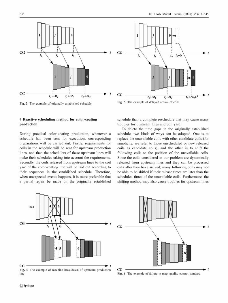
Since the practical production in nature is dynamic andrarely meets the static and deterministic assumption, thescheduling is an ongoing reactive process. Typical eventsrequiring reactive scheduling in color-coating productioninclude the delayed arrival of coils from upstream produc-tion lines and the failure to meet the quality required byorders. For simplicity, an originally established scheduleonly including the continuous galvanizing and the color-coating processes is shown in Fig. 3. Each coil j in thecontinuous galvanizing schedule is scheduled to be finishedat time tj and expected to arrive at the coil yard in front ofthe color-coating line at tj+Δtj. Then the typical eventsrequiring reactive scheduling can be described as follows.
3.1 Delayed arrival of coils
During practical color-coating production, some unexpect-ed events may cause coils unable to arrive on theiroriginally scheduled time. Generally, these unexpectedevents can be classified into two categories: (1) machinebreakdown of upstream production lines; (2) decreasedproduction rate or insufficient transportation ability.
3.1.1 Machine breakdown of upstream production lines
As is shown in Fig. 2, the color-coating production line hasmany upstream production lines. If any machine of theupstream production lines breaks down in practical pro-duction, all the coils assigned to it will be postponed until itis fixed. The example of this event is illustrated in Fig. 4.The coils 4, 5, and 6 are originally scheduled to beprocessed at machine CG-2 from time t1 to t2. However,the machine CG-2 breaks down at t1, and is expected to befixed until t2. Thus these coils cannot be delivered to thecolor-coating production line on their originally scheduledtime. The reactive scheduling is, therefore, needed to find
636 Int J Adv Manuf Technol (2008) 35:633–645
alternative coils from other normal machines or the coilyard to replace these unavailable coils.
3.1.2 Decreased production rate or insufficienttransportation ability
Besides the machine breakdown, some abnormal workconditions in the work floor such as decreased productionrate for disruptions on the control system or insufficienttransportation ability of cranes in coil yards connecting twoconsecutive production lines can also make coils unable tobe delivered on their originally scheduled time. Conse-quently, the color-coating schedule should be adjusted toavoid time gaps caused by the delayed coils. The exampleof delayed arrival of coils can be seen in Fig. 5. Supposethat the arrival time of coil 9 will be delayed to t9+δ, andthen this coil will be delivered to the color-coating line att9+Δt9+δ, which will result in a time gap in the color-
coating schedule. To deal with such a condition, thereactive scheduling method should find other coils ortransition coils in the coil yard and insert them into thesetime gaps.
3.2 Failure to meet the quality required by orders
During practical production, some coils may be unable tomeet their designed quality standard due to instability ofproduction equipments, and thus cannot be continued forfurther color-coating process. Figure 6 gives the example oftime gaps caused by failure to meet the required quality.Due to their failure to meet the quality standard specified bythe corresponding customers, the originally scheduled coils2 and 8 should be removed from the original schedule andreplaced with other coils. Such coils can be stored at thecoil yard for later use to match orders requiring lowerquality or act as transition coils.
Fig. 2 The schedule shown in the color-coating production scheduling system
Int J Adv Manuf Technol (2008) 35:633–645 637
4 Reactive scheduling method for color-coatingproduction
During practical color-coating production, whenever aschedule has been sent for execution, correspondingpreparations will be carried out. Firstly, requirements forcoils in the schedule will be sent for upstream productionlines, and then the schedulers of these upstream lines willmake their schedules taking into account the requirements.Secondly, the coils released from upstream lines to the coilyard of the color-coating line will be laid out according totheir sequences in the established schedule. Therefore,when unexpected events happens, it is more preferable thata partial repair be made on the originally established
schedule than a complete reschedule that may cause manytroubles for upstream lines and coil yard.
To delete the time gaps in the originally establishedschedule, two kinds of ways can be adopted. One is toreplace the unavailable coils with other candidate coils (forsimplicity, we refer to those unscheduled or new releasedcoils as candidate coils), and the other is to shift thefollowing coils to the position of the unavailable coils.Since the coils considered in our problem are dynamicallyreleased from upstream lines and they can be processedonly after they have arrived, many following coils may notbe able to be shifted if their release times are later than thescheduled times of the unavailable coils. Furthermore, theshifting method may also cause troubles for upstream lines
Fig. 3 The example of originally established schedule
Fig. 4 The example of machine breakdown of upstream productionline
Fig. 5 The example of delayed arrival of coils
Fig. 6 The example of failure to meet quality control standard
638 Int J Adv Manuf Technol (2008) 35:633–645
and coil yard even if the following coils can be shiftedbecause the shifting method will reposition many coils andthus make a relatively large change on the originallyestablished schedule. The shifting method is, therefore,not very appropriate for the reactive scheduling of color-coating production, and consequently we adopt the methodthat replaces the unavailable coils with candidate ones.
As described in the introduction section, to avoid thedisadvantage suffered by the greedy heuristics, we present arescheduling method that can simultaneously repair the timegaps in a global optimal view to minimize the impact on theoriginally established schedule and maintain its good quality.The rescheduling method consists of three stages: (1)replacing the unavailable coils with candidate coils basedon a matching-up model; (2) checking and restoring thefeasibility of the schedule using heuristic rules; (3) improv-ing the feasible schedule using a tabu search algorithm.
4.1 Stage 1: replacement based on the matching-up model
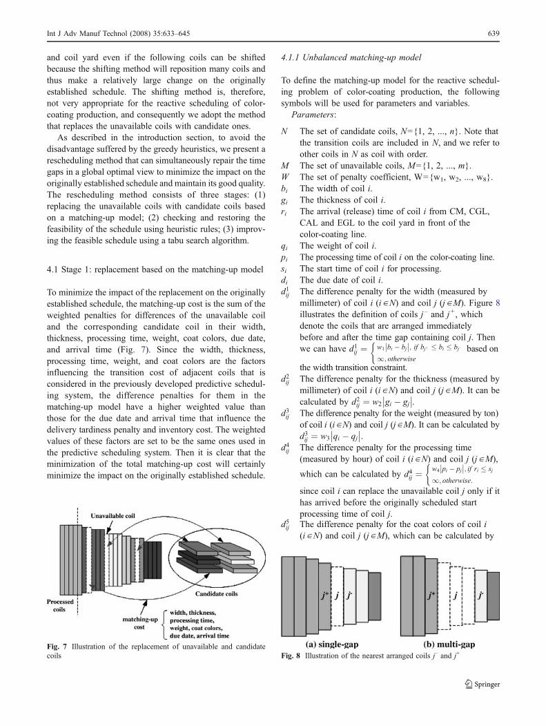
To minimize the impact of the replacement on the originallyestablished schedule, the matching-up cost is the sum of theweighted penalties for differences of the unavailable coiland the corresponding candidate coil in their width,thickness, processing time, weight, coat colors, due date,and arrival time (Fig. 7). Since the width, thickness,processing time, weight, and coat colors are the factorsinfluencing the transition cost of adjacent coils that isconsidered in the previously developed predictive schedul-ing system, the difference penalties for them in thematching-up model have a higher weighted value thanthose for the due date and arrival time that influence thedelivery tardiness penalty and inventory cost. The weightedvalues of these factors are set to be the same ones used inthe predictive scheduling system. Then it is clear that theminimization of the total matching-up cost will certainlyminimize the impact on the originally established schedule.
4.1.1 Unbalanced matching-up model
To define the matching-up model for the reactive schedul-ing problem of color-coating production, the followingsymbols will be used for parameters and variables.
Parameters:
N The set of candidate coils, N={1, 2, ..., n}. Note thatthe transition coils are included in N, and we refer toother coils in N as coil with order.
M The set of unavailable coils, M={1, 2, ..., m}.W The set of penalty coefficient, W={w1, w2, ..., w8}.bi The width of coil i.gi The thickness of coil i.ri The arrival (release) time of coil i from CM, CGL,
CAL and EGL to the coil yard in front of thecolor-coating line.
qi The weight of coil i.pi The processing time of coil i on the color-coating line.si The start time of coil i for processing.di The due date of coil i.d1ij The difference penalty for the width (measured by
millimeter) of coil i (i ∈N) and coil j (j ∈M). Figure 8illustrates the definition of coils j – and j +, whichdenote the coils that are arranged immediatelybefore and after the time gap containing coil j. Thenwe can have d1ij ¼ w1 bi � bj
�� ��; if bjþ � bi � bj�
1; otherwise
(based on
the width transition constraint.d2ij The difference penalty for the thickness (measured by
millimeter) of coil i (i ∈N) and coil j (j ∈M). It can becalculated by d2ij ¼ w2 gi � gj
�� ��.d3ij The difference penalty for the weight (measured by ton)
of coil i (i∈N) and coil j (j∈M). It can be calculated byd3ij ¼ w3 qi � qj
�� ��.d4ij The difference penalty for the processing time
(measured by hour) of coil i (i ∈N) and coil j (j ∈M),
which can be calculated by d4ij ¼w4 pi � pj
�� ��; if ri � sj
1; otherwise:
(
since coil i can replace the unavailable coil j only if ithas arrived before the originally scheduled startprocessing time of coil j.
d5ij The difference penalty for the coat colors of coil i(i ∈N) and coil j (j ∈M), which can be calculated by
Fig. 7 Illustration of the replacement of unavailable and candidatecoils Fig. 8 Illustration of the nearest arranged coils j– and j+
Int J Adv Manuf Technol (2008) 35:633–645 639
d5ij ¼ w5 � a (a is the number of different coat colorsbetween coil i and coil j).
d6ij The difference penalty for the due date (measured byhour) of coil i (i ∈N) and coil j (j ∈M), which can becalculated by d6ij ¼ w6 di � dj
� �. This formulation
means that coils with urgent due date will beencouraged to be selected, which can help to reducethe number of tardiness delivery coils.
d7ij The difference penalty for the arrival time (measuredby hour) of coil i (i ∈N) and coil j (j ∈M), which canbe calculated by d7ij ¼ w7 ri � rj
� �. This formulation
means that coils that arrived earlier will be encouragedto be selected, which can help to reduce the inventorycost of coils.
cij The matching-up penalty of coil i (i ∈N) and coil j(j ∈M), which is the weighted sum of the difference
penalties described above: cij ¼P7k¼1
akdkij where αkis
the weighted value of factor k. If coil i is a transitioncoil, cij =w8 qj, which reflects the penalty for thedecreased productivity cause by this transition coil.
Decision variables:
xij ¼1; if the candidate coil i is selected to
replace the unavailable coil j;
0; otherwise ; i 2 N ; j 2 M :
8<:
In the above parameters, the set of penalty W and thedifference penalties between two coils dkij k ¼ 1; :::; 7ð Þ are
the same ones used in the predictive scheduling system,which are determined based on both the experience ofhuman experts in the steel industry and the practicalproduction constraints. Therefore, it is clear that theminimization of the total matching-up cost will certainlyminimize the impact on the original schedules. With theparameters and the decision variable defined above, thematching-up model for the reactive scheduling problem canthen be formulated as follows.
minimizeXi2N
Xj2M
cijxij ð1Þ
s.t.Xj2M
xij � 1; 8i 2 N ð2Þ
Xi2N
xij ¼ 1; 8j 2 M ð3Þ
xij 2 0; 1f g; 8i 2 N ; 8j 2 M ð4ÞSince the transition coils are generally always available in
practical production, we can assume nQm. Then Eq. (2) en-sures that each candidate coil can match up at most oneunavailable coil. Equation (3) ensures that each unavailablecoil must be matched up exactly by one candidate coil. Equa-tion (4) specifies the integrity conditions on the variables.
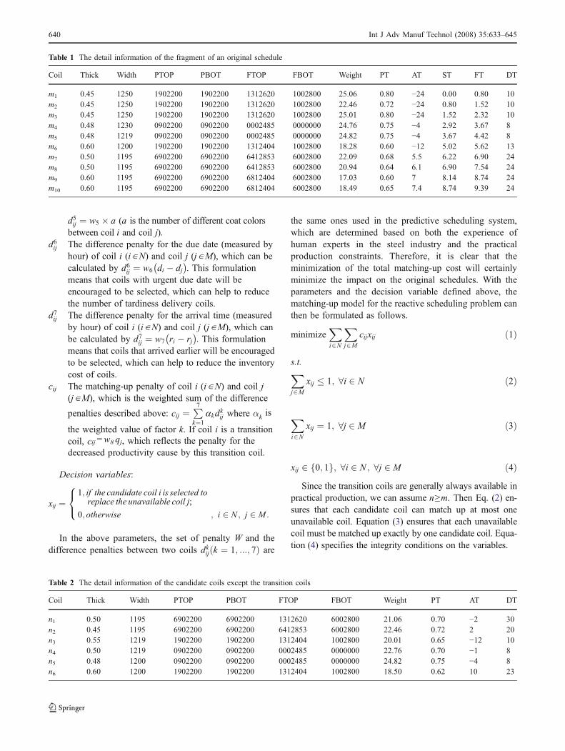
Table 1 The detail information of the fragment of an original schedule
Coil Thick Width PTOP PBOT FTOP FBOT Weight PT AT ST FT DT
m1 0.45 1250 1902200 1902200 1312620 1002800 25.06 0.80 −24 0.00 0.80 10m2 0.45 1250 1902200 1902200 1312620 1002800 22.46 0.72 −24 0.80 1.52 10m3 0.45 1250 1902200 1902200 1312620 1002800 25.01 0.80 −24 1.52 2.32 10m4 0.48 1230 0902200 0902200 0002485 0000000 24.76 0.75 −4 2.92 3.67 8m5 0.48 1219 0902200 0902200 0002485 0000000 24.82 0.75 −4 3.67 4.42 8m6 0.60 1200 1902200 1902200 1312404 1002800 18.28 0.60 −12 5.02 5.62 13m7 0.50 1195 6902200 6902200 6412853 6002800 22.09 0.68 5.5 6.22 6.90 24m8 0.50 1195 6902200 6902200 6412853 6002800 20.94 0.64 6.1 6.90 7.54 24m9 0.60 1195 6902200 6902200 6812404 6002800 17.03 0.60 7 8.14 8.74 24m10 0.60 1195 6902200 6902200 6812404 6002800 18.49 0.65 7.4 8.74 9.39 24
Table 2 The detail information of the candidate coils except the transition coils
Coil Thick Width PTOP PBOT FTOP FBOT Weight PT AT DT
n1 0.50 1195 6902200 6902200 1312620 6002800 21.06 0.70 −2 30n2 0.45 1195 6902200 6902200 6412853 6002800 22.46 0.72 2 20n3 0.55 1219 1902200 1902200 1312404 1002800 20.01 0.65 −12 10n4 0.50 1219 0902200 0902200 0002485 0000000 22.76 0.70 −1 8n5 0.48 1200 0902200 0902200 0002485 0000000 24.82 0.75 −4 8n6 0.60 1200 1902200 1902200 1312404 1002800 18.50 0.62 10 23
640 Int J Adv Manuf Technol (2008) 35:633–645
4.1.2 Transformation of the unbalanced matching-up model
To transform the unbalanced matching-up model to bebalanced, we introduce n–m dummy coils into M M 0 ¼ M[ðmþ 1; :::; nf gÞ and let cij=L (L is a very big number) for
i ∈N and j ∈ {m+1,...,n} so that |M′|=|N|. Then the balancedmatching-up model can be presented as follows.
minimizeXi2N
Xj2M'
cij xij ð5Þ
s.t.Xj2M 0
xij ¼ 1; 8i 2 N ð6Þ
Xi2N
xij ¼ 1; 8j 2 M 0 ð7Þ
xij 2 0; 1f g; 8i 2 N ; 8j 2 M 0 ð8ÞAfter initializing the information of the unavailable and
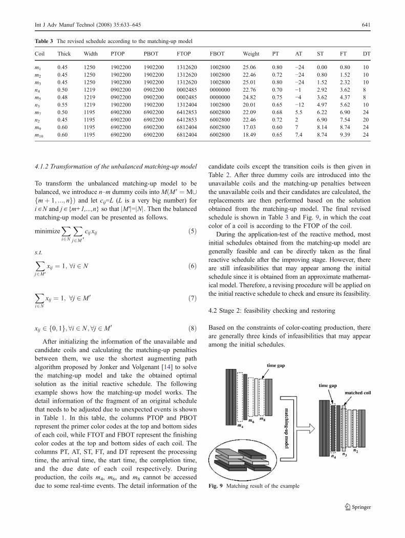
candidate coils and calculating the matching-up penaltiesbetween them, we use the shortest augmenting pathalgorithm proposed by Jonker and Volgenant [14] to solvethe matching-up model and take the obtained optimalsolution as the initial reactive schedule. The followingexample shows how the matching-up model works. Thedetail information of the fragment of an original schedulethat needs to be adjusted due to unexpected events is shownin Table 1. In this table, the columns PTOP and PBOTrepresent the primer color codes at the top and bottom sidesof each coil, while FTOT and FBOT represent the finishingcolor codes at the top and bottom sides of each coil. Thecolumns PT, AT, ST, FT, and DT represent the processingtime, the arrival time, the start time, the completion time,and the due date of each coil respectively. Duringproduction, the coils m4, m6, and m8 cannot be accesseddue to some real-time events. The detail information of the
candidate coils except the transition coils is then given inTable 2. After three dummy coils are introduced into theunavailable coils and the matching-up penalties betweenthe unavailable coils and their candidates are calculated, thereplacements are then performed based on the solutionobtained from the matching-up model. The final revisedschedule is shown in Table 3 and Fig. 9, in which the coatcolor of a coil is according to the FTOP of the coil.
During the application-test of the reactive method, mostinitial schedules obtained from the matching-up model aregenerally feasible and can be directly taken as the finalreactive schedule after the improving stage. However, thereare still infeasibilities that may appear among the initialschedule since it is obtained from an approximate mathemat-ical model. Therefore, a revising procedure will be applied onthe initial reactive schedule to check and ensure its feasibility.
4.2 Stage 2: feasibility checking and restoring
Based on the constraints of color-coating production, thereare generally three kinds of infeasibilities that may appearamong the initial schedules.
Table 3 The revised schedule according to the matching-up model
Coil Thick Width PTOP PBOT FTOP FBOT Weight PT AT ST FT DT
m1 0.45 1250 1902200 1902200 1312620 1002800 25.06 0.80 −24 0.00 0.80 10m2 0.45 1250 1902200 1902200 1312620 1002800 22.46 0.72 −24 0.80 1.52 10m3 0.45 1250 1902200 1902200 1312620 1002800 25.01 0.80 −24 1.52 2.32 10n4 0.50 1219 0902200 0902200 0002485 0000000 22.76 0.70 −1 2.92 3.62 8m5 0.48 1219 0902200 0902200 0002485 0000000 24.82 0.75 −4 3.62 4.37 8n3 0.55 1219 1902200 1902200 1312404 1002800 20.01 0.65 −12 4.97 5.62 10m7 0.50 1195 6902200 6902200 6412853 6002800 22.09 0.68 5.5 6.22 6.90 24n2 0.45 1195 6902200 6902200 6412853 6002800 22.46 0.72 2 6.90 7.54 20m9 0.60 1195 6902200 6902200 6812404 6002800 17.03 0.60 7 8.14 8.74 24m10 0.60 1195 6902200 6902200 6812404 6002800 18.49 0.65 7.4 8.74 9.39 24
Fig. 9 Matching result of the example
Int J Adv Manuf Technol (2008) 35:633–645 641

The first one is the discontinuity of production, which iscaused by time gaps between adjacent coils. Figure 10illustrates this kind of infeasibility. The processing time ofthe unavailable coil Sj is 50 min while the processing timeof its substitute S′i is 30 min. Then a time gap will appearbetween coils S′i and Sj+ because the earliest start time ofcoil Sj+ is sj+50. To repair such time gap infeasibility, threekinds of ways can be adopted: (1) Replace S′i with anothercandidate coil S′k which has the minimum matching-uppenalty with S′i and the processing time pk Q pj; (2) Find thebest combination of two or three candidate coils whose totalprocessing time can fill the time gap, and replace S′i withthem; (3) Find the best combination of another candidatecoil and a transition coil whose total processing time can fillthe time gap, and replace S′i with them. During thefeasibility restoring procedure, we evaluate all the threemethods and select the best one to be performed.
The second kind of infeasibility is the increasing patternof width transition. Such infeasibility only appears in thereplacement of continuous unavailable coils. To repair suchinfeasibility, two kinds of conditions should be considered:(1) if the infeasibility only involves two adjacent coils, then
replace one of them with another candidate coil orexchange these two adjacent coils to ensure the decreasingpattern of width transition (Fig. 11); (2) if the infeasibilityinvolves several continuous coils, then rearrange them orreplace some of them with other candidate coils when thesecoils cannot be rearranged to ensure the decreasing patternof width transition (Fig. 12).
The third kind of infeasibility is that the width orthickness transition between the selected candidate coil andits adjacent coils in the original schedule exceed thepermitted limitations. To deal with such a situation, wecan choose the best one from three ways: (1) replace theselected candidate coil with another one; (2) replace theselected candidate coil with a combination of another twoor three candidate coils; (3) insert appropriate transitioncoils at positions where the infeasibility appears.
Since in practical production appropriate transition coilscan always be available to replace those substitute coils thatcannot be available at its position specified by thefeasibility restoring procedure, feasible solutions canalways be obtained.
Fig. 11 Illustration of singleinfeasibility of width increasingand its repair methods
Fig. 10 Illustration of time gapinfeasibility and its repairmethods
642 Int J Adv Manuf Technol (2008) 35:633–645

4.3 Stage 3: improving the feasible schedule
4.3.1 A tabu search algorithm
After the feasibility of the reactive schedule is restored, atabu search algorithm with standard mechanism developedin the predictive scheduling system will be applied toimprove the schedule. The neighborhood of our tabu searchalgorithm is based on four edge-swapping operators: (1)Swap: swap two coils between two different turns or withinone turn; (2) Outer-relocate: remove a coil from a turn andthen insert it into another turn; (3) Inner-relocate: remove acoil from its current position in a turn and then insert it atanother position in this turn; (4) 2-opt: replace two edgeswith another two new edges. Note that the 2-opt operator isonly used for the post-improvement on the local optimaobtained by local searches in the neighborhoods specifiedby the first three operators.
4.3.2 Interactive adjustment
With the help of a graphical user interface shown in Fig. 2,the schedulers can easily obtain the information about theunavailable and candidate coils and then modify theobtained reactive schedule interactively with the schedulingsystem. Such modifications may include inserting candidate
coils into the schedule, deleting coils from the schedule,and repositioning coils in the schedule. For each modifica-tion, the scheduler can judge the quality of the modifiedschedule by using the evaluating function of the schedulingsystem, which will show a frame where relative objectiveitems concerned in production such as the number of colorswitches are given in detail.
5 Experimental results
To evaluate the performance of our proposed reactivescheduling method, we adopt the utility and stability measuresproposed by Ouelhadj et al. [12] and Cowling and Johansson[15]. The utility measures the improvement gained in theoriginal schedule objective function by using the reactivescheduling method, while the stability is used to measure thedeviation from the originally established schedule caused byschedule revision. Let S and S′ respectively denote theoriginal near-optimal schedule and the revised one. Let Edenote the real-time information obtained at time t. Then theutility measure can be expressed by Utility S; S0;E; tð Þ ¼ðf Sð Þ � f S0ð ÞÞ f Sð Þ= , where f (S) is the objective value of Sobtained by the predictive scheduling system under theassumption that no unexpected events will occur. The stabil-
Fig. 13 Performance of the utility and stability measures
Table 4 Experimental results on practical 60 instances
Instancegroup
Instancesize
Reactive method Manual
Utility Stability Utility Stability
1 373 −0.0453 0.0114 −0.2652 0.02302 312 −0.0235 0.0102 −0.2687 0.03203 386 −0.0311 0.0105 −0.234 0.04004 325 0.0387 0.0116 −0.2424 0.02175 329 0.0198 0.0198 −0.2537 0.06076 338 0.001 0.0168 −0.0637 0.0362Average −0.0067 0.0134 −0.2213 0.0356
Fig. 12 Illustration of continu-ous infeasibility of width in-creasing and its repair methods
Int J Adv Manuf Technol (2008) 35:633–645 643
ity measure can be expressed by Stability S; S0;E; tð Þ ¼PKi¼1
si � s0i�� ��
�PKi¼1
si, in which K is the number of coils in
the original schedule and s′i is the new start time of coil i forprocessing. Note that s′i is the start time of the selectedcandidate coil if coil i belongs to unavailable coils.
With the help of the developed predictive schedulingsystem that has been implemented in Baosteel, we havecollected six original schedules from practical color-coatingproduction, and based on these original schedules we use arandom strategy to generate the test instances for our reactivescheduling method. For one run of the random strategy, allthe real-time events described in Section 3, where each eventinvolves up to 10 coils, are generated at random positions ofan original schedule. We perform 10 runs of the randomstrategy on each original schedule, and thus, a total of 60 testinstances are generated and used in the experiment. To testthe performance of our reactive method, the generatedschedules with unexpected events are also given to theexperienced schedulers of Baosteel and then revised by thecurrent manual rescheduling system. The experimentalresults on the performance of the utility and stabilitymeasures of the proposed reactive scheduling method andthe current manual rescheduling system, which is essentiallya greedy procedure, on these instances are presented inTable 4 and Fig. 13. Note that each instance group includes10 instances and the results given are the average values ofeach group. Based on the results shown in Table 4 andFig. 13, we can make the following observations.
(1) With comparison to the original schedule, the pro-posed reactive scheduling method can provide satis-factory reschedules with only 0.67% deviation inobjective and 1.34% deviation in the scheduled timeof coils. Moreover, our method can even improvesome original schedules because more candidate coilshave been released from upstream lines when thereactive scheduling method is performed than whenthese original schedules are generated.
(2) The proposed reactive scheduling method outperformsthe current manual rescheduling system in both theutility and stability measures for all instances.
(3) The result nodes of the current manual reschedulingsystem in Fig. 13 are more dispersive than those of theproposed reactive scheduling method, which meansthat the proposed reactive scheduling method is morestable and robust than the current manual reschedulingsystem.
Furthermore, our proposed reactive scheduling methodcan provide satisfactory reschedules within one minuteduring the practical tests, while the current manualscheduling system generally takes about half an hour.
6 Conclusion
To efficiently deal with unexpected events during practicalcolor-coating production, we propose a predictive reactivescheduling method. Different from the previous greedystrategies proposed in the published literatures, the reactivemethod proposed in this paper is based on a matching-upmodel that can simultaneously repair the time gaps in aglobal optimal view. To ensure the feasibility of theschedule obtained by the matching-up model, a feasibilitychecking and restoring procedure using heuristic rules isthen performed. At last a tabu search algorithm developedin the previously predictive scheduling system is used toimprove the feasible schedule. With the help of thepredictive scheduling system, the proposed reactive sched-uling method has been tested in practical color-coatingproduction scheduling in Baosteel, the most advanced ironand steel enterprise in China. The experimental results oninstances randomly generated based on original schedulescollected from practical production show that the proposedreactive scheduling method can efficiently deal with theunexpected events and provide more robust and higherquality schedules under a real-time production environmentthan the current manual rescheduling system.
Since similar unexpected events exist in many produc-tion scheduling problems of the iron and steel industry, thefuture work will extend the investigation of the predictivereactive scheduling within other production schedulingsuch as the hot rolling production scheduling and thecontinuous galvanizing production scheduling.
Acknowledgements We thank the reviewers very much for theirhelpful comments and suggestions.
This research is supported by the practical project of Baosteel onthe Color-Coating Production Scheduling Research (Grant No.2004Z146BZ), and also supported by National Natural ScienceFoundation for Distinguished Young Scholars of China (Grant No.70425003), and National Natural Science Foundation of China (GrantNo. 60274049 and 60674084).
References
1. Matsuura H, Tsubone H, Kanezashi M (1993) Sequencing,dispatching, and switching in a dynamic manufacturing environ-ment. Int J Prod Res 31(7):1671–1688
2. Vieira GE, Herrmann JW, Lin E (2003) Rescheduling manufacturingsystems: a framework of strategies, policies, and methods. J Sched6:39–62
3. Church LK, Uzsoy R (1992) Analysis of periodic and event-driven rescheduling policies in dynamic shops. Int J ComputIntegr Manuf 5(3):153–163
4. Fang J, Xi Y (1997) A rolling horizon job shop reschedulingstrategy in the dynamic environment. Int J Adv Manuf Technol13:227–232
644 Int J Adv Manuf Technol (2008) 35:633–645

5. Naroska E, Schwiegelshohn U (2002) On an on-line schedulingproblem for parallel jobs. Inf Process Lett 81(6):297–304
6. Yamamoto M, Nof SY (1985) Scheduling/rescheduling in themanufacturing operation system environment. Int J Prod Res 23(4):705–722
7. Wu HH, Li RK (1995) A new rescheduling method for computerbased scheduling systems. Int J Prod Res 33(8):2097–2110
8. Park J, Kang M, Lee K (1996) Intelligent operations schedulingsystem in a job shop. Int J Adv Manuf Technol 11:111–119
9. Suh MS, Lee A, Lee YJ, Ko YK (1998) Evaluation of orderingstrategies for constraint satisfaction reactive scheduling. DecisSupport Syst 22:187–197
10. Akturk MS, Gorgulu E (1999) Match-up scheduling under amachine breakdown. Eur J Oper Res 112(1):81–97
11. Sun J, Xue D (2001) A dynamic reactive scheduling mechanismfor responding to changes of production orders and manufacturingresources. Comput Ind 46:189–207
12. Ouelhadj D, Cowling P, Petrovic S (2003) Utility and stabilitymeasures for agent-based dynamic scheduling of steel continuouscasting. IEEE International Conference on Robotics and Automation(ICRA 2003), Taipei, Taiwan
13. Sabuncuoglu I, Bayiz M (2000) Analysis of reactive schedulingproblems in a job shop environment. Eur J Oper Res 126(3):567–586
14. Jonker R, Volgenant A (1987) A shortest augmenting pathalgorithm for dense and sparse linear assignment problems.Computing 38:325–340
15. Cowling P, Johansson M (2002) Using real time information foreffective dynamic scheduling. Eur J Oper Res 139:230–244
Int J Adv Manuf Technol (2008) 35:633–645 645