a primer on cable pressurization maintenancea primer on cable pressurization maintenance due to...
TRANSCRIPT
A Primer on Cable PressurizationMaintenance
Due to operating company downsizing, and the resulting re-distribution of personnel,
there is a definite need these days for some basic information on cable pressurization.
While this information may seem obvious to an experienced pressure technician,
there are many people—at various levels of the telco organization—who are unfamil-
iar with pressurization. This primer is intended for anyone who would like to gain an
understanding of the importance, benefits, design characteristics, and basic compo-
nents of a cable pressurization system. It also describes some of the key management
functions required for a successful air pressure operation. To help familiarize you
with the terminology used, a brief glossary is provided at the back of this primer.
Why Are Telephone Cables Pressurized?
Types of Cable
Insulation
The biggest threat to telephone wires (conductor pairs) is moisture. Many of the cop-
per cables use paper or pulp as insulation between the individual conductor pairs.
This type of cable offers excellent insulation characteristics as long as it is main-
tained dry. Pulp insulation has been around for a long time, and for many years it had
essentially no competition. In more recent years plastic insulated conductor (PIC)
cable has encroached upon its popularity and has taken over the number-one spot.
Unfortunately, the integrity of the protective cable sheath (which is made of lead or
polyethylene) is compromised when cracks develop. The cracks in the sheath or as-
sociated splice cases allow water to enter and electrolysis to occur, which results in
faulted pairs within the cable.
All of us are familiar with moisture damage when the morning paper is left in the
rain. The characteristics of the paper change completely with the water damage. This
is the same thing that happens inside the cable sheath when water permeates it. The
first indication of moisture in a cable is noise on the line, followed by complete cable
failure.
Water and Cable
Pressure
In underground pulp insulated cable, a special problem develops due to water pres-
sure being applied to the outside of the protective sheath. And, since the cable is usu-
ally underground (often located several feet deep), a real disaster can occur when
utility holes fill with storm water.
System Studies Incorporated (16123.CPN) 1
A Primer on Cable Pressurization Maintenance

As water rises above a cable, there is approximately 0.43 Pounds per Square Inch
(PSI) of pressure applied for each foot of water level above the cable. So, for exam-
ple, if a cable is 7 feet below the surface and the utility hole fills with water, there
will be 7 x 0.43 (or 3 PSI) of water pressure bearing down on the cable. If there is a
crack in the cable or splice case, water will permeate and cause conductor damage
unless there is positive pressure within the cable that exceeds and counters the 3 PSI
of external force caused by the water.
Minimum Air
Pressure
Standards
This is the basic premise of cable
pressurization: Keep the pressure
within the cable in excess of the
pressure that could be applied by
standing water. To help achieve this
objective, telephone companies es-
tablish minimum air pressure stan-
dards for cables in different
environments. For example, an un-
derground cable (one that goes
through conduit and utility holes un-
derneath the street) might have a
minimum air pressure standard of 5
PSI, enough to protect the cable from
approximately 10 feet of water. A di-
rect buried cable requires less air
pressure protection (usually 3 PSI)
because it is placed only a foot or so
below the surface. Aerial cables typically require only 2 PSI because they are at less
risk from water damage.
Where Does the Air Pressure Come From?
Source Pressure The cable, although filled with individual conductors and associated insulation, is
much like a long garden hose carrying air pressure instead of water. The pressure
comes from a mechanical air compressor and dryer, located somewhere near the
telephone company cable vault. The compressor supplies the air at approximately 10
PSI, while the dryer removes the residual moisture. Essentially, this means that air
with very low humidity is forced into the cables.
How Is the Air Pressure Distributed?
Imagine once again that the cable route is like a garden hose. This hose is made up of
different sections that are many thousands of feet long. Depending upon its age and a
number of other variables, there will typically be leaks at various points along the ca-
ble. Like a hose, the pressure in the cable diminishes as the length increases. The
pressure must be re-established in the system along the route, or the cable will be un-
protected at substantial distances from the central office. Obviously, finding and fix-
2
A Primer on Cable Pressurization Maintenance

ing all of the leaks in the cable will help considerably. But, with technicians
constantly working on cables (opening splices, etc.) and with electrolysis being a
constant threat, air pressure must also be raised.
Benefits of
Air Pipe
One popular way of raising air pressure in the system is by using air pipe that fol-
lows the cable route and introduces pressure at various fixed points (Figure 1). Be-
cause the air pipe does not include conductors (which restrict the passage of air), it is
a far more efficient method of transporting air to the needed areas. The air pipe is
connected to a manifold which distributes air to the cables in the utility hole.
Air Pipe Endpoint
Pressure Standard
To make sure that adequate delivery pressure is supplied to the cables in the field,
most telephone companies set a minimum pipe endpoint pressure standard of 7.5
PSI. If the pipe pressure falls below this standard, cable protection is jeopardized. For
example, it’s impossible to maintain 5 PSI in an underground cable when the deliv-
ery pressure from the air pipe is only 4 PSI. For this reason air pipe delivery pressure
must be carefully monitored. Think of it as a main artery in the system. If pressure in
the air pipe is low, the whole system is low.
Should Maintenance Be Performedon a Routine Basis?
It is commonly thought that, once a cable leak has been found and fixed, the cable
will be safe from moisture. After a repair, there is a natural tendency to conclude that
“everything is okay” and that maintenance can be ignored until more leaks are found
on the cable. This couldn’t be further from the truth.
Maintaining a reliable cable plant is something like maintaining a large building. De-
terioration of the building must be taken seriously—especially the roof—which
should be frequently repaired to ensure extended use. Several parts of the country ex-
System Studies Incorporated (16123.CPN) 3
A Primer on Cable Pressurization Maintenance
CENTRAL OFFICE
CABLES
GROUNDLEVEL
UTILITYHOLE
COVER
AIR PIPEMANIFOLD(source ofpressure)
AIR PIPE
3000’ to 6000’ 3000’ to 6000’
Figure 1—Air Pipe System
damage. There’s no problem for buildings (and cables) when it doesn’t rain, but after
extended periods of neglect, they both require constant attention to fend off the water
problems when the storms come. Maintenance is best performed when the weather’s
dry.
Proactive Cable
Maintenance
Today, this type of routine maintenance is often called proactive maintenance. Many
telephone companies are shifting towards a proactive approach to the outside plant in
order to prevent subscriber calls, Public Utilities Commission (PUC) complaints, and
even catastrophic failure. It’s preventive medicine for the outside plant. Rather than
treating the outcome of poor health (big leaks and low delivery pressure), a good diet
and exercise program (changing out old cable/devices and performing maintenance
on the problematic routes first) will keep future problems from occurring.
Are Cable Leaks Hard to Find?
Air Flow
Analysis
When looking for leaks, an entire cable cannot be held under water (like a tire tube)
to look for bubbles at the point of damage. You have to devise another method. Pres-
sure readings will tell you that a cable is losing air, but they don’t tell you where. Be-
cause there is an inherent amount of air flow in pressurized cables, the best scheme is
to follow the air flow to the leak. By setting up check points and using devices to
measure the air flow, the leak can be quickly located without a foot-by-foot examina-
tion of the cable.
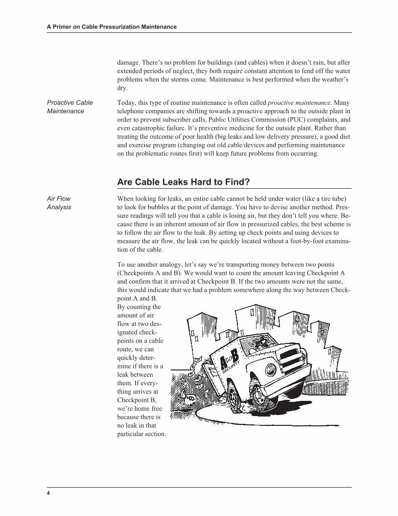
To use another analogy, let’s say we’re transporting money between two points
(Checkpoints A and B). We would want to count the amount leaving Checkpoint A
and confirm that it arrived at Checkpoint B. If the two amounts were not the same,
this would indicate that we had a problem somewhere along the way between Check-
point A and B.
By counting the
amount of air
flow at two des-
ignated check-
points on a cable
route, we can
quickly deter-
mine if there is a
leak between
them. If every-
thing arrives at
Checkpoint B,
we’re home free
because there is
no leak in that
particular section.
4
A Primer on Cable Pressurization Maintenance
How Is Air Flow Measured?
Flow Measurement
Standards
By far, the most accurate way to measure air flow is to count individual molecules.
To make this measurement more manageable, the molecules are measured by the box
full. The box size is a standard cubic foot (12" x 12" x 12"), measured at sea level (a
point of standard atmospheric pressure). The amount of standard cubic feet con-
sumed is measured either per hour or per day. This measurement lets you measure
high consumption rates (air dryer output) or relatively low consumption (air flow into
a cable) in a meaningful way, using Standard Cubic Feet per Day (SCFD) or Stan-
dard Cubic Feet per Hour (SCFH). These measurements help in monitoring for sys-
tem leaks and in cable maintenance.
Allowable Air
Consumption
Because of maintenance activity, cable splices, and the use of pneumatic fittings
along the cable route, all cables tend to leak to some extent. For this reason, an al-
lowable air flow rate, called Optimum Air Usage (OAU) has been established. OAU
is the calculated air consumption rate that an air pressure system should use under
normal operating conditions. It is based on a consumption rate of 1.25 SCFH per
sheath mile of cable.
Like the minimum air pressure standards, OAU is important in dispatching mainte-
nance technicians. A flow increase at an air source is not valuable information unless
you also know the OAU, or what the air source should be flowing. OAU is also im-
portant in the design of an air pressure system and for evaluating system quality.
What About Air Pressure?
Pressure
Measurement
Standards
As mentioned previously, most of the air distributed into a cable system is provided
by a mechanical air compressor/dryer. This central office equipment compresses or
squeezes air molecules together within a given area to create greater air pressure. It’s
kind of like a garbage compactor in some ways, but with a more useful end result.
The amount of compression is measured in Pounds per Square Inch or PSI. For
years, PSI readings were the only measurements being used in air pressure mainte-
nance. They’re still very important, but nowadays people have come to rely on both
pressure and air flow measurements.
And What’s Pneumatic Resistance?
Blockage of Air
Within a Cable
Another important concept in cable maintenance is pneumatic resistance. This is the
amount of resistance that air flow meets as it moves along inside the cable sheath be-
tween conductors. What determines the amount of pneumatic resistance in a particu-
lar section of cable are its length, the gauge of the conductors, the type of insulation
(PIC or pulp), and the number of pairs in the cable.
Pneumatic resistance must be taken into account when using pressure and flow meas-
urements when leak locating along a route. Together these three components com-
System Studies Incorporated (16123.CPN) 5
A Primer on Cable Pressurization Maintenance
prise the important information needed to perform many of the successful leak
locating formulas being used today.
What Is the Best Design for Protecting Cables?
In some ways, cable pressure systems are similar to municipal water systems. They
have main feeder routes and lateral sections of cable which branch off and serve cus-
tomers along the way. If you’re in an outlying residential area, far from the pumping
station, your water pressure is not going to be as great as the pressure on the main
feeder route. The water pipe serving your house is going to be much smaller than the
water main leaving the main station.
Lower Pressure
at the End of
a Route
Pressurized air is not supplied to the cables in an air pressure system by different size
pipes. Still, the pressure at the end of a cable route is always going to be less than at
the delivery source due to cable leaks and the pneumatic resistance of the cable.
When a leak occurs in a cable, it can result in a section of cable being totally unpro-
tected, depending upon the size of the leak and whether or not there is additional air
being supplied to the cable.
Design Types There are three basic engineering designs for protecting cables: a static system, a sin-
gle feed system and a dual feed system. Static systems were used before there was a
good method of supplying a continuous source of air to a cable (before air compres-
sors/dryers). They’re like bicycle tires—they hold pressure for a while, but eventu-
ally they will go flat.
Single feed systems pump air into the cables from one direction (one air source, such
as a central office air dryer). They provide adequate cable protection as long as there
are no serious leaks in the system. If you have a big leak, one that drops the cable
pressure to 0 PSI, the entire section of cable beyond the leak (on the side opposite the
air source) will have no air protection at all (Figure 2).
Dual feed systems prevent this from happening. They introduce air into the system at
different points along the cable route. As described previously, the most efficient
way to do this is with an air pipe. In a dual feed system, pressurized air converges on
a leak from opposite directions, supplying positive pressure protection to the sections
of cable between the leak and the two air sources (Figure 3).
What Makes Up an Air Pressure System?
System
Components
We’ve already mentioned some of the key system components: air compressors, air
pipe and air pipe manifolds. In the central office, where air is introduced into the sys-
tem, there are a number of other important system components. Distribution or meter
panels (referred to by either name) are rack-mountable equipment panels that regu-
late pressure from the air compressor and distribute it to the cables in the vault. Pipe
alarm panels provide the same function for air pipe leaving the central office. Both
panels are equipped with flow raters for physically checking outgoing flow rates.
6
A Primer on Cable Pressurization Maintenance

Cable Protection
Jeopardized by
Zero Leak
Improved Cable
Protection Even
With Leaks
Central Office
Monitoring
Devices
In well-designed systems, the central office panels are also equipped with pressure
and flow monitoring devices. These sensors, called transducers, monitor delivery
pressure and flow rates at the point of installation, but they cannot perform this func-
System Studies Incorporated (16123.CPN) 7
A Primer on Cable Pressurization Maintenance
CENTRAL OFFICE
CABLES0 PSILEAK
10
0
PR
ES
SU
RE
ADEQUATEPRESSURE
PROTECTION
PRESSURE GRAPH
DISTANCE
NO PRESSURE PROTECTION
Figure 2—Single Feed System
CENTRAL OFFICE
CABLES
AIR PIPE
0 PSILEAK
10
0
PR
ES
SU
RE
ADEQUATEPRESSURE
PROTECTION
ADEQUATEPRESSURE
PROTECTION
PRESSURE GRAPH
DISTANCE
Figure 3—Dual Feed System

tion by themselves. They must be wired to a central office monitor so that continual
device readings can be taken throughout the day and night.
Field Monitoring
Devices
In the field, pressure transducers are typically installed at the ends of cables and at
designated points along the cable route. The placement of these devices is critical in
the leak locating process. Flow transducers are also installed wherever air is intro-
duced in to the system. The most obvious field location is at an air pipe manifold.
Some systems use remote air dyers in the field to provide a boost in cable pressure.
These air sources are also monitored for pressure and for flow.
What’s the Current Status ofAir Pressure Management?
Over the years there have been a number of changes in the management of air pres-
sure systems. In order to be successful today, air pressure managers need to know the
quality of the cable pressurization system and what it costs to maintain that particular
level of quality. With this information they can make intelligent decisions regarding
where to dispatch technicians and, just as importantly, where not to dispatch them.
Cost Analysis
Controls
Keeping track of the labor hours spent on cable maintenance per sheath mile of cable
is a key cost analysis control. It may take some effort initially to obtain sheath mile-
age data, but once this information is known maintenance tasks can be evaluated to
determine labor hour efficiency. When this information is compared with a rating of
the quality of the system, effective management decisions can be made.
How is Monitoring Being Improved?
New instrumentation and computer programs, such as the PressureMAP™ Manage-
ment Analysis Program, have simplified cable maintenance and given management
much greater control over dispatching and labor hours. This software program ob-
tains monitoring device data from office monitors, analyzes it, and provides valuable
management and maintenance reports.
Management
Analysis Software
One of PressureMAP’s most valuable tools is its
“high five” report. In the past managers would
have to manually pour over
pages and pages of monitor-
ing system printouts each
morning in order to deter-
mine where to dispatch
technicians. PressureMAP
eliminates this function by
carefully analyzing pressure
and flow conditions and prioritizing the five most important leak
locating tasks in each office. This capability frees up manage-
8
A Primer on Cable Pressurization Maintenance
ment time and eliminates the stress and confusion of “on-the-spot” dispatching.
System Quality
Rating
PressureMAP also provides an early warning alarm system wherein damaged cable
problems can be detected before conductors get wet. Alarms are received from office
monitors, evaluated to determine if they need immediate response, automatically
verified if determined to be of alarm status, and distributed to assigned centers or
personnel for immediate response. This type of reactive capability is a vast improve-
ment from the monitoring systems of old, where an alarm status represented a drop
below or a step above a programmed device threshold.
PressureMAP’s System Quality Index (SQI) uses pressure readings and air flow rates
per sheath mile of cable to provide an accurate measurement of the status of a sys-
tem—both by office and by route. The standard SQI rating is between 80 and 85. In-
dexes above the optimum represent excessive maintenance (“goldplating”). Low
indexes are the result of one or more factors: too few labor hours being spent in an
office/route, inadequate/inaccurate engineering, poor dispatching, and/or a lack of
proper leak locating skills.
But what’s even more important for today’s telephone operations is the software’s
proactive capabilities. Not only does PressureMAP identify system-threatening con-
ditions and dispatch technicians accordingly, it also offers the tools to systematically
improve the cable pressurization system. This proactive function helps eliminate ex-
pensive after-hour alarm response time and makes it possible to schedule key mainte-
nance activities. To use an earlier analogy, this is the difference between making
needed repairs to your roof at your convenience, or having to do the work in the
pouring rain.
Summary
The reasons behind cable pressurization are basically easy to understand. The main
goal of pressurization is to protect the cables from water damage—keep cable pres-
sures above the minimum standards established for the various cable environments.
When cable pressure is low, it’s typically the result of two things: low delivery pres-
sure or actual cable leaks.
Monitoring devices in the central office and field help make it possible to identify
both types of problems and determine the cause of low cable pressure. In the case of
cable leaks, air flow analysis makes it possible to prioritize which leaks are doing the
most damage to the system. With a knowledge of Optimum Air Usage, you can eas-
ily distinguish between a good flow and a bad flow. And once you know this, air
flow leak locating techniques can be used to help locate the large, system damaging
leaks.
Air pressure design is an important factor in the success of an air pressure operation.
Certain designs, such as dual feed, offer better cable protection than others. An air
pipe system is one of the best means for providing dual feed protection to cables, but
it is not cost effective for every type of air pressure operation. For this reason, there
System Studies Incorporated (16123.CPN) 9
A Primer on Cable Pressurization Maintenance
are alternative dual feed design systems available which provide many of the same
protection and monitoring capabilities of the more expensive systems.
Improvements in air pressure monitoring have made it easier to analyze system con-
ditions and perform important management and maintenance functions. These soft-
ware programs offer greater tools and controls for today’s cable pressurization
managers and maintenance technicians. They emphasize a proactive approach to ca-
ble maintenance while, at the same time, providing superior alarming and dispatch-
ing capabilities.
Cable pressurization is an important part of today’s telephone operations. The tech-
nology being used in this field has evolved rapidly in the past decade, and improve-
ments are continually being made. For more information on basic cable pressuriza-
tion, system design components, proactive maintenance and alarming, please contact
System Studies Incorporated.
10
A Primer on Cable Pressurization Maintenance

Pressurization Glossary
The following terms are provided to assist in the understanding of key pressurization
terms as they are used today by various engineering, maintenance and construction
personnel. It is essential in the development and upkeep of a cable pressurization sys-
tem that all participating departments be familiar with these terms.
Actual Air Usage (AAU) AAU is a measurement of the total air consumption that
an individual air source (such as an air pipe manifold) is using at a given time. AAU
can be compared with Optimum Air Usage (OAU).
Aerial An elevated or overhead cable, or transducer that is associated with an ele-
vated cable.
Air Dryer See Central Office Compressor.
Air Flow Calculation A formula used to determine how much air is passing through
a section of cable at a given point in time.
Air Pipe Plastic CA 3131 pipe used to distribute pressurized air from the central of-
fice compressors to the air pipe manifolds in the field. Typical air pipe is a 12 inch in
diameter, and has an aluminum lining to prevent vaporization.
Air Pipe Manifold A cable pressurization hardware device located in the field.
Pneumatically connected to an air pipe, a single air pipe manifold distributes air to as
many as five individual cables.
Air Pipe Purification The systematic identification of all air consumption on an air
pipe, section by pipe section.
Air Pressure Index See System Quality Index.
Air Pressure Record See Pressure Record.
Air Source Any of a number of types of equipment designed to introduce pressur-
ized air into a cable pressurization system. This equipment includes central office
compressors or air dryers, air pipe manifolds, and remote air dryers.
Alarm The notification by an air pressure monitor or monitoring software of an un-
desirable condition existing within the pressurized cable network that requires cor-
rection.
Auxiliary Air Source A supplementary (other than central office) source of pressur-
ized air, such as a remote dryer or nitrogen cylinder.
B-Meter Panel See Distribution Panel.
Back Projection A formula used in single feed cable sections to determine the dis-
tance (in feet) to leak from an air source (or bypass valve).
System Studies Incorporated (16123.CPN) 11
A Primer on Cable Pressurization Maintenance
Buffering A supplemental and temporary source of air supplied to a cable system in
order to maintain pressure in a cable during splicing activity.
Buried A cable, transducer, or other pressurization device that is direct-buried, with
no protective conduit.
Butterfly Map A field verification aid used to systematically list the contents and
position of all pressurization items in a utility hole. The butterfly map provides the
means of organizing and recording air pipe and cable duct assignments, air pipe
manifolds, transducers, splice cases, load coils, pressurization hardware, etc.
Bypass Valve An arrangement of tubing designed to circumvent a pneumatic plug
in a cable. The bypass has a shutoff valve so that air flow around the plug can be
controlled.
Cable Paired and insulated conductors (fiber optics, quads, videos or coaxials)
formed into a compact core and covered with a protective sheath.
Cable Network All pressurized cable within a specified geographical area.
Cable Pressurization Automatic Monitoring System (CPAMS) Microprocessor-
based equipment designed to remotely monitor a pressurized cable network. It is a
user-programmable monitor that interfaces with standard teletype printers or com-
puter terminals to provide pressure and flow information upon request or at predeter-
mined intervals.
Cable Route A defined cable path out of a central office used to organize and group
telephone cables. Cables are generally associated with an air pipe and grouped by
route according to the direction in which they are headed.
Central Office (CO) The starting point, or “hub” of a cable pressurization sys-
tem—the inside plant.
Central Office Compressor A mechanical device that compresses ambient air
molecules, extracts the moisture from the air, and pumps the dry air into the cable
network via the central office panels.
Central Office Manifold A collecting tube which combines either the low or high
side air outputs of two air dryers into a single air source. The air is then directed to
the pipe alarm panels.
Central Office Sector The circular area surrounding the central office that contains
all the cables fed by distribution panels. The boundary of the CO sector is located at
a point approximately half-way to the first air source in a dual feed system, or ap-
proximately 3,000 feet out from the office in a single feed office.
Check Valve A valve that allows air to flow in one direction only. The check valve
is commonly installed in-line on tubing connecting the manifold to the air pipe.
Conductor Insulation Material surrounding a wire conductor that protects it from
electrical interference. the two types of insulation are paper (pulp) or PIC.
12
A Primer on Cable Pressurization Maintenance
Contactor A remote pressure sensor used to signal a drop in air pressure to a preset
level. The contactor is a simple on/off device with a resistive output of 540 kilohms
in the normal condition and 270 kilohms in the alarm condition.
Dedicated Pair A pair of wires exclusively assigned to report data from a transducer
to an office CPAMS.
Delivery Pressure A pressure measurement at a point where air enters the pressur-
ized cable network.
Device See Monitoring Device.
Device Type A device designation based on the device’s position and function
within the pressurization system.
Distribution Panel A central office panel used in an air pipe system. Usually con-
sidered the first manifold on the cable run, the distribution panel is often referred to
as the meter or B-meter panel.
Dual Feed System A cable pressurization system that provides pressurized air to
both ends of a pneumatic section.
Electrolysis Damage to cable pairs caused by the interaction of moisture and electri-
cal current.
End Point The pneumatic end of an air pipe or cable.
Flow Range A flow transducer’s factory-calibrated flow measuring parameters.
Typical flow ranges are 0–10 SCFH, 0–19 SCFH, 0–50 SCFH, and 0–100 SCFH.
Flow Rate The amount of air flow in a pressurized cable system over a period of
time. This flow is commonly measured in Standard Cubic Feet per Hour (SCFH) or
in Standard Cubic Feet per Day (SCFD).
Flow Transducer An electronic device which measures the rate of air flow at its
point of installation and transmits this information back to a CPAMS. Flow transduc-
ers are commonly installed at pipe alarm panels, air pipe manifolds, and at remote
dryers. Two basic types of flow transducers are in use: mechanical, resistive devices,
and 4–20 milliamperes, solid-state devices.
Frame Interconnect Block The apparatus in the central office where individual
transducer circuits are wired. The connection from the frame interconnect block to an
automatic monitoring system is completed by use of 25 pair cables.
Hardware The physical components of a cable pressurization system, and/or spe-
cific computer equipment. Cable pressurization hardware may be classified as field
hardware or central office hardware.
Interlacing The pneumatic connection of one cable to another, originally designed
to increase pair capability. However, an unfortunate leak-masking side effect results
System Studies Incorporated (16123.CPN) 13
A Primer on Cable Pressurization Maintenance
when pressurized cables are interlaced—air pressures equalize. All interlacing should
be plugged.
Junction A point within a cable network where two or more pressurized cables meet
(not a point where one cable is extended with another of the same gauge, size, and
distribution).
Labor Efficiency Indicator (LEI) A rating system used to gauge the efficiency of
cable pressurization maintenance efforts. The LEI is a comparison of an office’s Sys-
tem Quality Index (SQI) and the number of labor hours that have been expended to
maintain the office at the SQI level.
Labor Hours The number of hours used to maintain the air pressure systems (ex-
cluding hours for system installation).
Lateral A single fed pneumatic cable section that branches out from a main feeder
cable.
Manifold See Air Pipe Manifold.
Meter Panel See Distribution Panel.
Minimum Air Pressure Standards The minimum amount of internal pressure
needed to protect a cable. Generally, the minimum pressure for underground cable is
5 PSI, 3 PSI for buried cable, and 2 PSI for aerial cable.
Modem An acronym for MOdulator/DEModulator, a modem is a device that con-
verts digital data into audio tones suitable for transmission over regular telephone
lines.
Monitor See Cable Pressurization Automatic Monitoring System.
Monitoring Device A remote electronic sensing device that monitors pressure, flow,
or other conditions. Monitoring device data is accessed by a CPAMS.
Optimum Air Usage (OAU) A standard air flow rate per sheath mile of cable. The
OAU indicates what consumption should be under ideal conditions. OAU can be
computed for any air source.
Office Index See System Quality Index.
Open An open circuit. When monitoring pressure and flow transducers and contac-
tors, any measurement exceeding 6.5 megohms in resistance is considered an open
circuit. A trunk/toll cable loop resistance reading greater than 8190 ohms is an open.
Pipe Panel A regulating and monitoring device located in a central office. The pipe
panel regulates air pressure from the central office dryer(s) and monitors air flow to
an air pipe.
Pipe Purification Procedure This procedure verifies the location of all air consum-
ers along an air pipe run. It also helps to identify all pneumatic sections on an air pipe
run in order to ensure complete monitoring. See Air Pipe Purification.
14
A Primer on Cable Pressurization Maintenance

Plastic Insulated Cable (PIC) Cable containing conductors that are insulated with a
coating of either polyethylene or polypropylene.
Pneumatic Plug See Pressure Plug.
Pneumatic Resistance The characteristic restriction of air flow through a cable. The
resistance is a function of the gauge of the conductor, the insulation surrounding the
conductors, and the number of conductors.
Pneumatic Section The basic unit of cable pressurization. A section of cable whose
pneumatic boundaries are defined by air sources or pneumatic plugs. The introduc-
tion of a new air source at any point in an existing pneumatic section (other than one
of the end points) creates at least one additional pneumatic section.
Pressure The force exerted by compressed air against its enclosure—the interior
wall of a cable, air pipe or air dryer. Pressure is commonly measured in Pounds per
Square Inch (PSI).
PressureMAP Monitoring software used for cable pressurization alarming and
analysis.
Pressure Plug An intentional blockage of air flow through a cable. The plug creates
a pneumatic dam within the cable sheath.
Pressure Record A finished stickmap or cable map that graphically displays the ar-
rangements of the various parts of a cable pressurization system. It includes detail
boxes containing air pipe, cable, and monitoring device information. Depending
upon the specific design, there can be several types of pressure records for each of-
fice.
Pressure Transducer A device used to remotely measure air pressure in the pres-
surized cable network. The transducer has an electrical output that varies with
changes in pressure. Generally, the pressure transducer is calibrated in Pounds per
Square Inch Gauge (PSIG). Two basic types of pressure transducers are in use: me-
chanical, resistive devices, and 4–20 milliamperes, solid-state devices.
Pressurization System A pressurized cable network contained within a specific
geographical area, made up of the following three essential components:
n Hardware Used to introduce air and maintain air pressure, system hardware
includes air dryers, air pipe manifolds, central office panels, and pneumatic
plugs.
n Monitoring Equipment Used to sense changes in air activity, this equipment
includes CPAMS, transducers, and contactors.
n Tools Instruments and procedures used to maintain pressure within a cable
network.
Proactive Maintenance Performing maintenance on a routine basis in order to pre-
vent serious air pressure problems from occurring in the future.
System Studies Incorporated (16123.CPN) 15
A Primer on Cable Pressurization Maintenance

Pulp Cable Paper insulated cable. Each conductor is wrapped in paper insulation to
inhibit electrical interference. Pulp cable has a relatively high pneumatic resistance.
Remote Air Dryer A compressor located outside the central office. The remote air
dryer is designed to pump dry air into a cable pressurization system. It is generally
used when air feed out of the central office is impractical.
Remote Air Source A source of air supply to a pressurization system outside the
central office. These sources supplement pressure feed from the central office. Re-
mote air dryers and nitrogen cylinders are examples of remote air sources.
Riser Pole The pole or other point at which a cable emerges from the underground
into an aerial environment.
Routining A systematic, proactive approach to leak locating in a pressure route or
zone. When a cable route is routined, all air leaks are identified and repaired section
by cable section.
Splice Location along cable where pairs have been joined together or altered in
some manner.
Splice Case Protective case on cable allowing access to telephone conductor pairs.
Standard Cubic Foot per Hour (SCFH) A common measure of air flow rate based
on the standard cubic foot—a “box” of air measuring 1 foot on each side. The meas-
urement indicates the rate of air (of number of standard cubic foot boxes) flowing
past a given point in a pressurization system in 1 hour.
Standard Cubic Foot per Day (SCFD) A measurement of the rate of air flowing
past a given point in a pressurization system in one day.
Sheath A casing made of polyethylene or lead that surrounds and protects a cable
from the elements.
Sheath Mile A unit of cable measurement equal to 5,280 feet used to calculate Opti-
mum Air Usage.
Single Feed System A cable pressurization system in which air is supplied to a ca-
ble, or cables, from only one source.
Sphere of Influence The section of cable or cables most directly affected by an air
source delivery pressure. In a dual feed system, the area of pressurization encompass-
ing all pressurized cables extending in both directions and ending at a point on the
cable midway between manifolds.
Stickmap The initial engineering drawing of a complete cable route showing the
number of air pipes, utility hole locations, number of cables in a utility hole, air pipe
manifolds, transducers, and other pressurization equipment. It is a working drawing
intended to be updated as information is compiled.
16
A Primer on Cable Pressurization Maintenance
Subscriber Pair A pair of wires assigned for subscriber service on which monitor-
ing device equipment is sometimes installed.
System Quality Index (SQI) A measurement of the quality of cable protection in a
given route, office, or district. The System Quality Index (SQI) is a formula based on
average cable pressures and air flow per sheath mile of cable. The output of the SQI
is a relative number where 90 is standard.
Underground A cable or transducer that is located in conduit or ducts. It is not bur-
ied directly in the ground.
Vault Underground compartment where cables leaving the central office are housed.
Zero Leak Projection A formula that limits the area of search when a section of ca-
ble is being investigated for a leak. The calculation is used to determine the farthest
point on a cable that a leak could be from an air source or measurement location.
System Studies Incorporated (16123.CPN) 17
A Primer on Cable Pressurization Maintenance

18
A Primer on Cable Pressurization Maintenance