a product model to support plm-based variant planning …
TRANSCRIPT

SYSTEMS ENGINEERING AND DESIGN 1741
INTERNATIONAL DESIGN CONFERENCE - DESIGN 2012 Dubrovnik - Croatia, May 21 - 24, 2012.
A PRODUCT MODEL TO SUPPORT PLM-BASED VARIANT PLANNING AND MANAGEMENT
M. Kreimeyer
Keywords: product structure, product architecture, early phases of engineering design, variant management
1. Introduction Product Data Management (PDM) and Product Lifecycle Management (PLM) are an essential part of the necessary infrastructure to enable efficient variant management and engineering collaboration in any larger firm [Arnold et al. 2005]. An important part of developing such a system is the concept of how the different artefacts are handled. This concept typically takes shape as a general and later a detailed business blueprint that is based on the product structure or product architecture template, i.e., the different levels the product is (abstractly) broken down into and the rules of configuration that guide the assembly and the linkup to other departments and their views, e.g., production or sales. This paper details the general concept for a generic product structure at MAN Truck & Bus AG (below referred to as “MAN”), Munich, Germany, and the experiences made during its development. The interest of the paper is to show the industrial shape that product structure takes as the basis of a PLM implementation. It therefore takes up the results of architecture and PLM focused research and applies it to the specific circumstances at MAN. Thus, it regards, first, the background of this work (section 1), briefly reviews the state of the art (section 2) and the existing context and boundary conditions at the company that set the scope for the product architecture in focus (section 3), to then develop a three-layer product architecture model that is intended to handle the product structure of both heavy and light trucks, buses and engines, the three main divisions at MAN (section 4). A case study from bus development is used to illustrate the use and review the practicability (section 5) before the paper is concluded (section 6).
1.1 Background and project context
MAN is a major producer of commercial vehicles, selling light and heavy duty trucks, city and long distance buses and components thereof, e.g., engines. The primary niche MAN occupies is that of mass customization for specialized markets. As such, MAN vehicles are built on a highly modular architecture that supports a wide range of applications, e.g., trucks for different uses (e.g., wood transport, military, etc.) and market segments (such as long-haul, distribution or traction). While trucks cater for variants necessary for these different vehicles from a mostly pre-documented (i.e., pre-developed) set of components, buses are developed to order to a certain degree, especially for customers from the public segment. As for now, variant management (i.e., documenting components and their configurability into overall vehicles) is executed mostly ex-post by the departments responsible for the bill of material. The bill of material itself is a complex host-based IT system that manages approximately 100,000 different parts and their relationships (Fig. 6 shows a screenshot). In a current initiative, a more targeted variant management is being introduced with the goal to develop and document only those parts that are, in fact, needed from a customer’s point of view. To this end, new processes to support the early phase are being introduced, namely a specification phase

SYSTEMS ENGINEERING AND DESIGN 1742
to generate a set of product specifications in a formal manner, a product architecture phase to translate the functional specifications into consistent vehicle architecture, and a package phase to ensure the product architecture is collision-free for the intended variant models. As these processes do not have any specific IT-support yet, they are the main scope of the introduction of a Product Data Management (PDM) system intended to support both a more targeted variant management and the global collaboration between the company’s engineering sites. This paper shows the initial concept for a product structure that supports the processes in the early phases of design. It was developed as part of a feasibility study, which preceded the main PDM introduction project in collaboration with several engineering and IT departments at MAN and supported by Mieschke Hofmann und Partner as a consulting agency.
1.2 Process implementation in an industrial context
History has shown that many introductions of PDM/PLM systems have failed, mostly due to a lack of alignment with processes in the company or due to a lack of acceptance in the different engineering departments [Sosa et al. 2004]. In a similar manner, literature and experience from practice points out that abstract methods often cannot be applied “as is” in industry and thus only find their application to a limited extent. Industrial experience shows that a process, however, cannot be developed “by PowerPoint”, but that its implementation is only possible through organizational measures such as forms, workflows and a dedicated IT support to guarantee repeatability, precision and completeness. At the same time, limited flexibility is needed without permitting too many workarounds that cancel out the overall effect the support system has. For the introduction of a PDM/PLM system, this reflects in the separation of a primary product structure managed solely in the PDM system, while secondary structures coexist in different (and thus specialized) departments and systems, offering a localized degree of freedom to staff. The differentiation is made from an entrepreneurial point of view: While those elements of interest to the overall company (e.g., as synchronization points) remain in the primary structure, secondary structures are those that are more dynamic or localized, e.g., the assembly structures within the 3D-CAD system or the breakdown structure of properties regarded in product benchmarks.
1.3 “Structure” in this context
“Structure” regards, in this context, the pattern in the network formed by dependencies (edges) between the product architecture’s entities (nodes) as well as their taxonomies (i.e., generic decompositions). It reflects the semantics of this network; the structure of a system therefore always contributes – in its decomposition – to the purpose of the system [Boardman and Sauser 2006], i.e., the description of different product variants, their constituents and how these are configured to form individual products. The structure thus emerges, to a large part, from existing products [Koppel 1987].
2. State of the art Product architectures and their linkup to efficient process design have shown a long history.
2.1 Representations of product architectures
Different means of representing product architectures exist. Most commonly in engineering design research, the Design Structure Matrix (DSM) and related methods are used [Ulrich and Eppinger 1995], [Bonjour 2008]. Using a square matrix (or a related set of matrices such as shown in the Multiple-Domain Matrix [Kreimeyer and Lindemann 2011]), the entities of the product and their relationships are modelled to derive structural characteristics, such as tightly coupled clusters that can then be transferred into modules or such as bridges that can serve as interfaces between two modules of a product. To handle variants in a company at a larger scale, they are not appropriate, as e.g., large examples from process management show [Kreimeyer and Lindemann 2011]. However, the matrices are very suitable for high-level architectures and general systems integration. In many respects, methods like Quality-Function-Deployment or the House of Quality follow this approach, too.

SYSTEMS ENGINEERING AND DESIGN 1743
Another modelling scheme is to use variant trees that show a decomposition of a product based on its variant characteristics (e.g., left hand steering and right hand steering) to determine the rules of variant generation and the ultimate set of possible configurations [Eversheim and Korreck 2001]. Such models can be applied either to analyse an existing portfolio of components to identify variant drivers and their economic impact or to plan new variants as part of a product family [Blees et al. 2010]. Further means of representing and managing product architectures include functional modelling or graph based methods (e.g., graph grammars) that are not regarded here (see e.g., [Zagel 2007]).
2.2 Product data management and product lifecycle management
As opposed to the methods shown in the previous section, product architecture modeling for PDM/PLM applications and IT is focused more on the meta-level, i.e., taxonomies and relationship types or configuration rules. A common model in industry is the SAP iPPE model (see e.g., [Sendler 2009]). The modeling approach in this paper makes use of parts of this model, therefore. Furthermore, several “neutral” formats exist that embed product architecture data; in automotive industry, especially STEP AP 214 based on ISO 10303 is a common means [Sendler 2009]; a more generic set is provided by STEP AP 233, which is closely related to SysML. Callahan [2006] details such an architecture model for Boeing that serves as a basis for its embedding in an IT system. Using UML, the structure shown is intended to enable the consistent management of variants, supporting the consistent data management based on a high-level architecture. [Sendler 2009] provides a wider overview of PDM/PLM approaches at Audi, Blohm + Voss, Claas, Heidelberger, Voith and Siemens Transportation. All these companies set different foci but concentrate on engineering processes with their solutions, based on a detailed model of the product structure. E.g. Claas follows a very similar approach to the one shown below. The main common aspects that are modeled are, usually, three levels of a product structure, a portfolio level, a configuration level, and a part level. According to the markets served and business model used, the methods behind these levels vary from company to company. Companies with stable product topologies (i.e., limited geometrical variance but a high variance in materials, surfaces, and the like) will approach a more geometry-oriented configuration, as those geometrical modules will not change much and provide a stable basis. Passenger vehicle manufacturers, therefore, model the occurrence of a geometrical location as a direct entity in their variant structures, whereas commercial vehicle manufacturers will change the positioning of their components according to the overall setup a vehicle’s configuration. Other drivers are, for example, the product and sales philosophy. While some manufacturers only adapt their portfolio in the market once per year, others do so more often. This impacts, in particular, the portfolio layer and how the models or types of a product that organize the overall portfolio are aggregated and transferred into downstream processes.
3. The rationale for a product structure at MAN With the above goals, the following section shows the basic rationale that was used to develop a product architecture model for MAN. Further details on the existing company structures are, in particular, available through the company service portal www.manted.de. To reduce the effort of introducing a new PDM system and to make use of existing structures at MAN, a detailed analysis was run on how variants and, more generally, design documentation is managed. The driver was, on the one hand, to make use of existing structures and templates at MAN to absorb the experience embedded therein, and, on the other hand, to facilitate the transition process to the new system by being able to argue that it only extends but does not replace existing data structures. In retrospective, this was one of the most important enables for a fast acceptance within the organization, as both the understanding of how the product structure is set up and why it is extended can be argued starting from data that most engineers are already aware of. Essentially, there are two types of structures present – product oriented structures and process / project oriented ones. Below, both are explained in more detail. However, for a first concept, in particular the product oriented structures were regarded to embed these in an overall product structure model. This will later be extended and refined to integrate with project management, too.

SYSTEMS ENGINEERING AND DESIGN 1744
3.1 Existing structures at MAN that form the basis for a product structure
As of now, only few formal structures are used throughout the MAN design process. These structures build the basis for the setup of the product structure model shown below, because the existing structures are not to be replaced but integrated. The process is, essentially, characterized by three major milestones. During the definition phase, the development project and its input data are specified, generating the project ID and the set of specifications. During the concept phase, these specifications are used to generate a technical concept for the product to be developed. This concept is then detailed and verified in the design and simulation/testing departments during the design phase to generate release packages (i.e., the sets of geometry etc. that go into individual releases), regrouping part numbers, the 3D CAD models and respective drawings for each part number and the sales assembly groups, i.e., the bills of material for individual modules a customer can order when configuring a desired vehicle. These sales assembly groups are later codified, i.e., they are linked to sales codes that serve as a basis for the sales system and that carry the constraints and dependencies among the assemblies and the vehicle; as such, they define the codes (i.e., what options that a customer can select, e.g., the capacity of the fuel reservoir) that can be chosen for a vehicle and what sales assembly group (representing the specific bill of material for geometry, parameters, handbooks etc.) is applicable to build the vehicle accordingly.
Figure 1. Different structures and their interdependencies from a sales’ perspective
Figure 1 shows how these different structures interact from a sales perspective. Overall, the structures can be grouped into three layers – a product portfolio layer that regroups the available vehicles at a coarse level of detail, a property layer that independently classifies the properties any vehicle could (theoretically) have and that serves as a basis for the vehicle configuration for the customer, and the solution layer that collects the part numbers (and therefore the underlying engineering elements) that serve as the overall solution portfolio that MAN offers. The sales assembly group connects these three layers by generating small modular bills of material for each code that specifies a property class; an example for a property class would, e.g., be the vehicle’s air conditioning system, and a specific code would therefore point to the choice of an auxiliary heating system that a customer could choose (none, low-power, high-power, automatic,...). For different basic vehicles, this heating system could take different shapes (piping, cabin size, etc.). Similarly, on the context of other coexisting codes, the heating could use different mounts or be placed in a different position. Therefore, the sales assembly group combines the variant context as specified by the basic vehicle (given by approx. ten codes, e.g., maximum permissible load, arrangement of axles, cabin size, engine type,...), the chosen property (as given by the code), and the part numbers including the positioning (as given by the assembly drawing that is connected to the sales assembly group.

SYSTEMS ENGINEERING AND DESIGN 1745
3.2 Separating variant characteristics
The complexity of vehicles is driven by three characteristics on the engineering side. Firstly, the functional variance that is provided to the market drives complexity; e.g., for a truck, about 5,000 options are theoretically possible, although they never occur all for one vehicle (typically, a customer specifies 400 to 600 properties to generate a complete vehicle). Secondly, these properties are embodied using different components (e.g., components by different suppliers). Lastly, the positioning of the components in the vehicle context varies importantly for otherwise comparable vehicles; e.g., the installation of a fuel reservoir depends on many other components, such as the existence of a spare wheel, as well as on the vehicle setting (e.g., a road tanker cannot have a fuel reservoir on the right hand side of the vehicle, as this is where the fuel hoses for the tanker are installed). These three aspects (function, technical alternative, positioning) are managed in combination using the sales assembly groups, i.e., if one of the aspects changes (or is impacted through other coexisting sales assembly groups), a new sales assembly group has to be created and thus managed to cater for this change. While such a process is manageable for the later phases of engineering design, it does not support the early phases, as often the above aspects are not fully determined yet, while the product is concretized only little by little. In the new product architecture model, it was therefore decided to separate these aspects and their management. This builds the basic foundation for the architecture model that is shown below and illustrates why the existing structures were not used as-is.
3.3 Supporting downstream processes
The above criteria all relate to the determination of the configuration logic used to configure vehicles or parts thereof; thus, to support processes, relevant data is associated to the nodes of the product structure [Sendler 2009]. At the same time, the overall architecture model is intended to be as lean as possible, as only a structure that can be controlled as such will persist over a longer period (i.e., support different future process models or forms of organization). Therefore, the criterion whether specific information is part of the primary structure (as shown in this paper) or the secondary structures (as existing in different departments) is determined by the need for this information in downstream processes. If, e.g., the static radius of a wheel is later needed for homologation, it is carried as an attribute at the level of the primary structure; if, however, it is only needed locally in the homologation process, it is not part of the primary structure. The separation of the primary and secondary structures, however, is an ongoing process and only mentioned in the following where needed.
3.4 Extending collaboration scenarios
Lastly, an important characteristic of the product architecture model is to support the designation of responsibilities in a finely granular manner to support different collaboration scenarios with other partners, such as MAN Latin America or with joint venture partners in China or India. To this end, a change management process across all entities of the product architecture model as well as designation of roles and responsibilities at different levels of granularity of the product architecture is currently being designed. This, however, is not part of this paper.
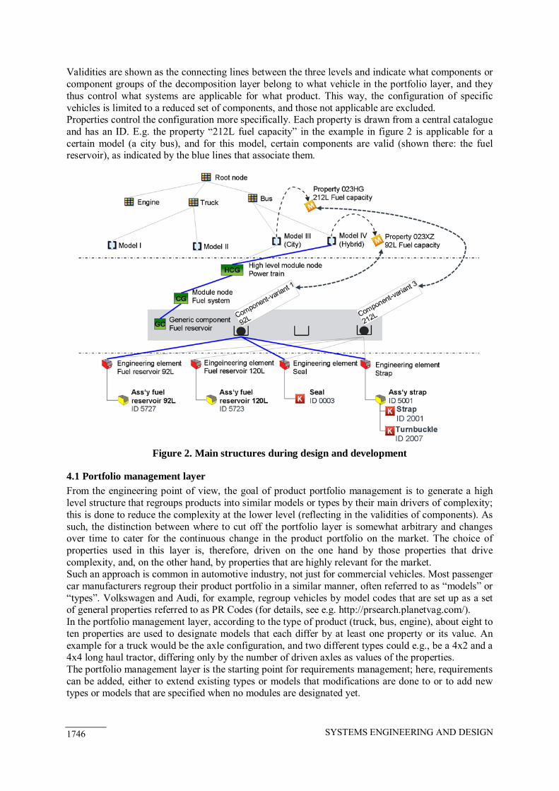
4. The concept for a product structure The overall product structure is separated into four layers (specifically, three layers and the connecting properties that link the layers). The first layer supports the management of the product portfolio by regrouping different types of products across the overall range of products. Specifically, the three divisions of MAN – truck, bus, and engine development and production – are supported here through a common template. The second layer, the product decomposition layer, provides a generic taxonomy for the different systems that are used to build each vehicle, i.e., it regroups assemblies and components, electric systems and parameters, and so on. Lastly, the lowest layer, the solution space, collects the different engineering elements, such as parts or parameters, and their documentation, e.g., CAD files or drawings. The three layers are connected, on the one hand, via validities and via properties that control the configuration, on the other hand.
SYSTEMS ENGINEERING AND DESIGN 1746
Validities are shown as the connecting lines between the three levels and indicate what components or component groups of the decomposition layer belong to what vehicle in the portfolio layer, and they thus control what systems are applicable for what product. This way, the configuration of specific vehicles is limited to a reduced set of components, and those not applicable are excluded. Properties control the configuration more specifically. Each property is drawn from a central catalogue and has an ID. E.g. the property “212L fuel capacity” in the example in figure 2 is applicable for a certain model (a city bus), and for this model, certain components are valid (shown there: the fuel reservoir), as indicated by the blue lines that associate them.
Figure 2. Main structures during design and development
4.1 Portfolio management layer
From the engineering point of view, the goal of product portfolio management is to generate a high level structure that regroups products into similar models or types by their main drivers of complexity; this is done to reduce the complexity at the lower level (reflecting in the validities of components). As such, the distinction between where to cut off the portfolio layer is somewhat arbitrary and changes over time to cater for the continuous change in the product portfolio on the market. The choice of properties used in this layer is, therefore, driven on the one hand by those properties that drive complexity, and, on the other hand, by properties that are highly relevant for the market. Such an approach is common in automotive industry, not just for commercial vehicles. Most passenger car manufacturers regroup their product portfolio in a similar manner, often referred to as “models” or “types”. Volkswagen and Audi, for example, regroup vehicles by model codes that are set up as a set of general properties referred to as PR Codes (for details, see e.g. http://prsearch.planetvag.com/). In the portfolio management layer, according to the type of product (truck, bus, engine), about eight to ten properties are used to designate models that each differ by at least one property or its value. An example for a truck would be the axle configuration, and two different types could e.g., be a 4x2 and a 4x4 long haul tractor, differing only by the number of driven axles as values of the properties. The portfolio management layer is the starting point for requirements management; here, requirements can be added, either to extend existing types or models that modifications are done to or to add new types or models that are specified when no modules are designated yet.

SYSTEMS ENGINEERING AND DESIGN 1747
4.2 Product decomposition layer
The product decomposition layer addresses, essentially, a configuration-oriented decomposition of all existing products at MAN down to the level of functionally similar subsystems. While a purely functional description (such as e.g., “store energy” instead of “fuel tank”) was discussed extensively as it offers the possibility to design solutions with fewer restrictions, the factual decomposition follows the considerations for a modular kit the product is set up from, i.e. each component group or generic component shown represents a subsystem of the overall vehicle that can explicitly be selected or deselected when configuring a specific variant model. The product decomposition layer makes use of different classes of information. Generic components, and their grouping into component groups, refer to functions that are embedded by a subsystem. Component-variants describe the different technical implementations that can be used for each generic component, e.g., from a conceptual point (left/right hand steering, for example), a technological point (e.g., steel or aluminium tank) or other. The layer therefore does not designate the usage of a component variant, but all assemblies of this modular kit are, first, independent of their application in a vehicle. The usage only comes in later as a result of the configuration – in other terms, all component variants are modelled independently, and they are filtered into specific variants only by “applying” them to, on the one hand, types or models of the portfolio layer and, on the other hand, associating them with the appropriate properties that drive a component-variant.
Figure 3. Variant specification
The purpose is to generate a structure that serves as a common language across all the company’s divisions that, so far, still use different ways to document and structure their products. To be able to do so and to generate a structure that outlasts reorganization efforts in the company or new process templates, it needs to be independent of both the organizational and the process setup. Furthermore, it needs to be more abstract than the factual solution layer, i.e., the description embedded in the part numbers, as the structure is meant to serve not only as a taxonomy for existing part numbers but also for parts that are being designed and therefore do not follow the numbering scheme yet. On the other hand, the product decomposition layer and its structure are intended to allow for the variant configuration of vehicles in the early phases of the design process. This is done to allow both the design in context for adaptations of parts of a product in the overall variant spectrum as well as to allow for the early specification of variants necessary from a customer’s point of view without “overdeveloping” variant models that are, in fact, not needed. Figure 3 shows the basic mechanism for this configuration approach. On the left hand side of the figure the specification phase is shown and the right hand side visualizes how a concrete design is made out of this specification. During the specification phase, a set of (by then still preliminary) models are specified, e.g., a 2-wheel-drive truck and a 4-wheel-drive one. For each of these models, properties are defined that serve as collectors for the requirements related to a property the customer can later order; thus, the specifications from a customer’s point of view from his desires to possible configurations of a vehicle are anticipated. The figure shows two possible models (I and II) and four properties (P 1 to P 4) that are specified in the example. The properties are, furthermore, related to each other using Boolean
SYSTEMS ENGINEERING AND DESIGN 1748
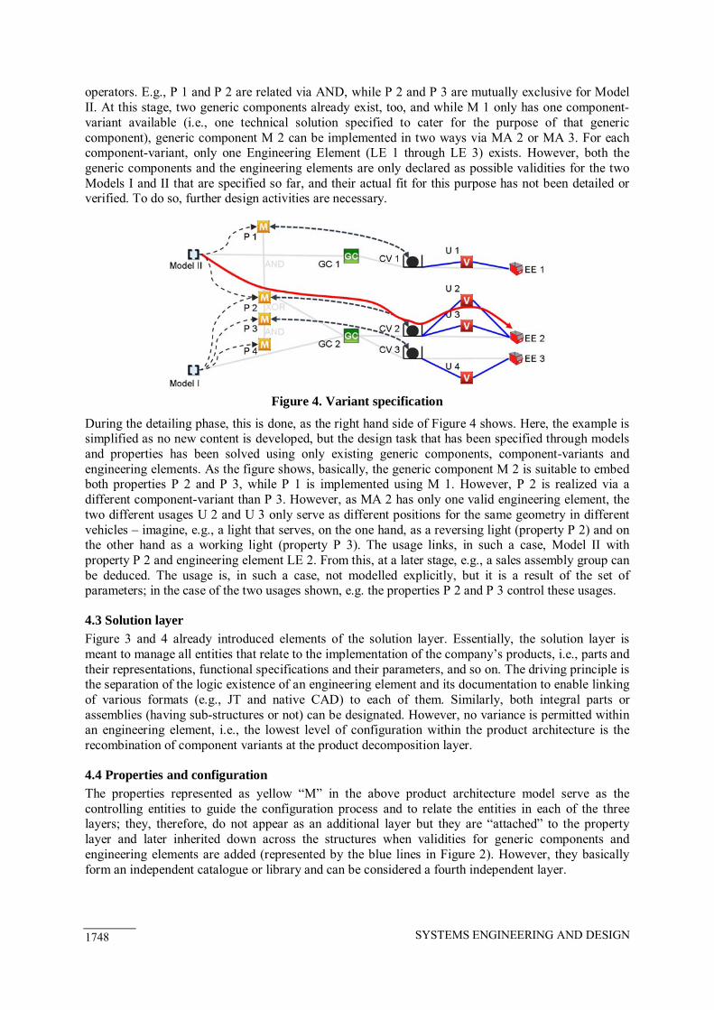
operators. E.g., P 1 and P 2 are related via AND, while P 2 and P 3 are mutually exclusive for Model II. At this stage, two generic components already exist, too, and while M 1 only has one component-variant available (i.e., one technical solution specified to cater for the purpose of that generic component), generic component M 2 can be implemented in two ways via MA 2 or MA 3. For each component-variant, only one Engineering Element (LE 1 through LE 3) exists. However, both the generic components and the engineering elements are only declared as possible validities for the two Models I and II that are specified so far, and their actual fit for this purpose has not been detailed or verified. To do so, further design activities are necessary.
Figure 4. Variant specification
During the detailing phase, this is done, as the right hand side of Figure 4 shows. Here, the example is simplified as no new content is developed, but the design task that has been specified through models and properties has been solved using only existing generic components, component-variants and engineering elements. As the figure shows, basically, the generic component M 2 is suitable to embed both properties P 2 and P 3, while P 1 is implemented using M 1. However, P 2 is realized via a different component-variant than P 3. However, as MA 2 has only one valid engineering element, the two different usages U 2 and U 3 only serve as different positions for the same geometry in different vehicles – imagine, e.g., a light that serves, on the one hand, as a reversing light (property P 2) and on the other hand as a working light (property P 3). The usage links, in such a case, Model II with property P 2 and engineering element LE 2. From this, at a later stage, e.g., a sales assembly group can be deduced. The usage is, in such a case, not modelled explicitly, but it is a result of the set of parameters; in the case of the two usages shown, e.g. the properties P 2 and P 3 control these usages.
4.3 Solution layer
Figure 3 and 4 already introduced elements of the solution layer. Essentially, the solution layer is meant to manage all entities that relate to the implementation of the company’s products, i.e., parts and their representations, functional specifications and their parameters, and so on. The driving principle is the separation of the logic existence of an engineering element and its documentation to enable linking of various formats (e.g., JT and native CAD) to each of them. Similarly, both integral parts or assemblies (having sub-structures or not) can be designated. However, no variance is permitted within an engineering element, i.e., the lowest level of configuration within the product architecture is the recombination of component variants at the product decomposition layer.
4.4 Properties and configuration
The properties represented as yellow “M” in the above product architecture model serve as the controlling entities to guide the configuration process and to relate the entities in each of the three layers; they, therefore, do not appear as an additional layer but they are “attached” to the property layer and later inherited down across the structures when validities for generic components and engineering elements are added (represented by the blue lines in Figure 2). However, they basically form an independent catalogue or library and can be considered a fourth independent layer.

SYSTEMS ENGINEERING AND DESIGN 1749
The properties are based on the codes shown in Figure 1, existing currently only to formalize the configuration process in the sales IT systems. These codes are only available late in the design process; in the early phases, a similar construct is available through the product properties, where early product features that a customer is expected to order are created. The property as shown in the product architecture model serves, thus, as an overarching structure that guides the transition from the anticipated feature as specified in the early phases via the engineering code that guides the development of generic components and component-variants to the final transfer into the production BOM and the sales system that embeds the finalized product into codes. These codes are, therefore, the essential backbone of the design process, as Figure 5 shows.
4.5 Consequences in process application
Figure 5 visualizes how the transition from the product specification to the finalized design reflects in the filling level of the product architecture model. At first, during the definition phase, the design project is concretized, and the requirements are specified. Therefore, new models (where necessary) as well as the properties these models are to have are detailed; the properties also carry the detailed requirements, possible target values and the required way of measuring these target values and thus serve as a connection point to the requirements management process. During this first phase, generic components and, where applicable, carry-over-parts can be specified already, too.
Figure 5. “Filling” the structure during the different phases of design and development
During the concept phase, the requirements are transferred down to generic components and component-variants including the interfaces between these generic components (i.e. the first high-level configuration that does not yet relate to part numbers). As such, either existing component-variants are assigned to the structure, or new generic components and component-variants are designated that, in a next step, need to be designed. Lastly, during the design phase, engineering elements and the respective sub-structures (CAD files etc.) are added and specified; this also refines the relevant properties assigned to the component-variants, thus detailing the possible usages that a component variant is applicable to. This way, the final vehicle BOM is implicitly set up during the design process.
5. An illustrative example In this section, a short illustrative example from the design of a city bus (Lion’s City solo bus) is shown. It regards the example of the sales assembly group of a fuel reservoir and how its elements are distributed in the product architecture model regarded in this paper. Figure 6 shows, on the right, a reduced screenshot (for nondisclosure reasons, some elements were removed) of the current BOM system and the entities that are collected in such a BOM; the screenshot regards one individual sales assembly group (ID 1146 – IDs have been altered from the original denomination for the purpose of this paper). On the left hand side, this assembly is shown including

SYSTEMS ENGINEERING AND DESIGN 1750
the entities it contains, i.e., the assembly drawing that contains the positioning of the parts, different assemblies (with and without substructures) as well as individual components (i.e., their serial numbers). The assembly group is related to a property class that regroups all properties related to, in this case; fuel reservoirs (class 0230). For each of these elements, one or more pieces of documentation exist, e.g., different CAD files that relate to the components, as well as drawings for each component. These are accessible within the company through the serial number. Figure 2 shows the same model, linking up with the IDs listed in the original BOM as shown in Figure 6. The example shows a scenario of reusing a set of engineering elements from an existing city bus that has a specified fuel capacity of 212 litres, available in the sales system via the order code 023HG. This code is embedded in the sales group 1146 that, in the product structure, reflects in usage 1146 (this is coincidental, a sales group and a usage do not always need to be fully analogous). This usage is not shown in the figure, but it reflects, in this case, in the three engineering elements selected by the leftmost component variant.
Figure 6. Sales assembly group (left) and its bill of material (screenshot current system)
The scenario in Figure 6 also shows this reuse as a new bus model IV, representing a hybrid bus with a smaller fuel volume represented through code 023XY, which is not yet embedded at that time. It makes use of the existing product decomposition to come to a new generic component that has only been generated out of the finer repartition of engineering elements that, now, are recombined to produce a new usage 11XZ re-assigning some existing entities. Of course, this way, also a new positioning of the parts and new assembly documentation is generated, stored as position ID 85XZ.
6. Conclusion and further work The paper presents an industrial approach for a harmonized product architecture across the different divisions at MAN Truck & Bus AG, allowing for a targeted variant management by enabling the early configuration of variant models in a given product context. As such, it presents a high-level concept, created top down making use of existing structures in the company. It is based on the existing state of the art, customized to meet demands in the company; the orientation on the state of the art primarily of how modern PDM/PLM IT systems are programmed serves, above all, to lower IT costs that would, otherwise, be induced through maintenance and customization.
6.1 General reflexion
Overall, the design of the illustrated structure was done over approximately two years, and the concept was reworked several times over; yet, over time, the show aspects (three levels, configuration mechanism, separation of positioning concept, decomposition methodology) have stabilized over time and have been sharpened, but not changed substantially. From a conceptual point of view, the concept is therefore considered stable. In the separation of the aspects of variance reflected (function, technical implementation, positioning) reflects a difference to passenger vehicle business, where the positioning of components is less of an

SYSTEMS ENGINEERING AND DESIGN 1751
issue; as, however, a commercial vehicle is largely based on a spectrum of wheel bases and other positions, and this, thus, is an important driver of complexity that needs to be taken into account. The separation of the different aspects of complexity has been well received in the company; the original planning methodology using sales assemblies has, overall, been perceived as more complex, as the criteria as to when a new sales assembly was to be created were more manifold. The installation of properties as the guiding entities throughout the design process is another advance that has come out of the presented conceptual work, as thereby, the transition from the specifications to a technical concept to the final bill of material now has a guiding entity. From a PLM point of view this helps setting up the data model, as the configuration of different products is always driven by a similar set of properties that are the backbone of the design process. The fact that these properties mirror the sales process (essentially, the specification process is the same as the sales process but run “upside down”) further aids the acceptance in the company, as no new structures were introduced. Lastly, the finer splitting of components as compared to the original sales group now allows to compute different views (as “secondary” structures) based on the presented structure; e.g. the positioning is an example, as the individual solution elements first need to assigned to their respective coordinate system (and these may not be in a 1:1 relationship to the product decomposition). Another example is, e.g. the allocation of target costs to groups of components.
6.2 Reflexion on the implementation at MAN
The presented structure is currently being implemented at MAN at a larger scale; all larger design projects use it as a publication structure for their concept design and as a framework to transfer and apply the specifications to the concept design phase. This, of course, implies a major change, as up to now project teams were much less formally constrained in how they wanted to structure their design tasks. Obviously, such a change is difficult to implement in a larger company, and it is, therefore, accompanied by a professional change management approach with e.g. various information and training sessions throughout all impacted divisions and departments. The awareness and need is, in most cases, not easy to explain, especially as long as only theoretical concepts exist. Real cases studies and an increasing number of users acting as change agents are, thus, the most important enablers to convince the staff of adopting the provided new product structure. Another enabler was to colour the structures – the decomposition is internally known as “the green structure”, as a consistent colour scheme was used for all elements in the overall model. The biggest change, to this end, is the strong formalization of the design phase; here, the individual, often very creative approaches existing so far, now need to be aligned to follow a general architecture design. While most engineers recognize that having a common decomposition that improves the precision of the common language (what is part of an assembly, what is not?), the higher effort for documentation and the need to respect the boundaries set by the decomposition are, often, perceived as a hindrance. Therefore, a large part of the training is to make the business need for such an approach more transparent; in summary, the higher data quality and the consistent documentation are the two most acceptable arguments to this end. At the same time, the formalization of the process in the early phases and its documentation also implies the need for a formal change process to ensure that the structure stays “clean” and is not adapted as needed. This challenge is not finally solved yet but is currently in focus. The common language goes hand in hand with a common configuration approach; again, in the past, the configuration was described individually on the drawings, not following a specific method, which introduced a higher number of errors. Little by little, now, a more consistent description is being introduced, which aids the overall quality of design documentation. The most complex undertaking was the initial setup of the product decomposition in a way that it serves as a harmonized structure across the whole company; overall, a bottom up approach in a more “democratic” manner failed, as the large number of participants needed (stakeholders from all major departments) could not come to a common conclusion and as many members were faced with a lack of time to tackle such an abstract problem on their own. In consequence, a top-down design of the decomposition was generated and discussed individually with all stakeholders (about 200 over 10 months); the final state of this decomposition has been formally released by the CTO and is now in

SYSTEMS ENGINEERING AND DESIGN 1752
use. However, this decomposition still is not final, as details (such as piping, shared components, and more depend on the new technical concepts (e.g. steer by wire needs different components than a conventional steering system). Therefore, all larger design projects are accompanied by architects, who follow up on such changes and who improve the decomposition accordingly. With the model being designed to be applicable to MAN, the scalability to other partners has not been verified yet; however, the use of properties as a generic layer and the finer decomposition of assemblies indicate that other structures could be incorporated; however, this has not been verified yet. For the initial time of implementing the structure (roughly the next five years, as an estimate), no effects on cost or lead times are expected; rather, the relevant business case is focused on enabling new processes, such as DMU and package processes that, previously, were not possible in depth.
6.3 Scientific implications and further work
Lastly, a few new questions have come up during the design of the presented product structure model. Above all, the question of modularity or modular kits has come up often. However, it was decided to keep this issue out of the product structure for now, as no clear understanding across the company could be generated yet. The clear designation of standardized modules is, from the industrial point, not conclusively clear, yet. The understanding that was taken in the model for now is that, essentially, modules can occur at any level of the product decomposition or in the solution space. The next step will, therefore, be a detailed review of how platform and modular design take shape for commercial vehicle design – it will, most likely, reflect in standards for the topology of certain classes of vehicles, e.g. fixed positions, spaces, packages, and the like.
References Arnold, V., Dettmering, H., Engel, T. and Karcher, A., “Product Lifecycle Management”, Springer, Berlin, 2005. Blees, C., Jonas, H. and Krause, D., “Development of Modular Product Families”, 12th International DSM Conference 2010, Cambridge, England. Boardman, J. and Sauser, B., “System of Systems – the Meaning of of”, IEEE/SMC International Conference on System of Systems Engineering. Los Angeles. pp. 6-12 (IEEE, 2006). Bonjour, E., “Contributions à l'instrumentation du métier d'architecte système : De l'architecture modulaire du produit à l'organisation du système de conception”, Université de Franche-Comté, Besançon, 2008. Callahan, S., “Extended Generic Product Structure: An Information Model for Representing Product Families”, Journal of Computing and Information Science in Engineering, 2006, 6(3), pp. 263-276. Eversheim, W. and Korreck, A., “Variant Management - Management of complexity between market and production”, International Conference on Competitive Manufacturing COMA 2001, University of Stellenbosh, RSA. pp. 479-492. Koppel, M., Complexity, depth and sophistication. Complex Systems, 1987, 1(6), pp. 1087-1091. Kreimeyer, M. and Lindemann, U., “Complexity Metrics in Engineering Design”, Springer, Berlin, 2011. Lindemann, U., “Human Behaviour in Design”, Springer, Berlin, 2003. Sendler, U., “Referenzbuch des Produkt-Lebenszyklus-Managements“, Springer, Berlin, 2009. Sosa, M., Eppinger, S.D. and Rowles, C.M., “The Misalignment of Product Architecture and Organizational Structure in Complex Product Development”, Management Science, 2004, 50(12), pp1674–1689. Ulrich, K. and Eppinger, S., “Product Design and Development”, McGraw-Hill, New York, 1995. Zagel, M.,“Übergreifendes Konzept zur Strukturierung variantenreicher Produkte und Vorgehensweise zur iterativen Produktstruktur-Optimierung“, Universität Kaiserslautern, Kauserslautern, 2007. Dr. Matthias Kreimeyer MAN Truck & Bus AG Dachauer Str. 667, 80995 Munich, Germany Telephone: +49 89 158063958 Email: [email protected]