a proofing, templating and purposing engine in java and c#/ · a proofing, templating and purposing...
TRANSCRIPT

A Proofing, Templating and Purposing Engine in Java and C#/.NET Margaret Sturgill, Steven Simske HP Laboratories Palo Alto HPL-2002-272(R.1) January 31, 2006* publishing, templating, proofing, .NET, Java, repurposing
A UI-controlled application for proofing, template definition, groundtruth determination, and enabling of multi-purposing/re-purposing was simultaneously engineered in JAVA and in C#/ .NET incorporating, asneeded, legacy C++ libraries. Fulfilling the quality assurance requirements of a print-on-demand (printing, publishing & metadata tagging) process, the application also provides a ready means fortemplating, ground truthing & repurposing capabilities by allowingborders and region (bit depth, type) specification. Its output is in XML in accordance with a general schema written to provide sufficient metadatafor publishing, repurposing & template definition. This user-defined data set also comprises "ground truth" of the viewed image and thus is bydefinition a 100% accurate representation of the current image layout.We also compare and contrast the implementation in the Java andC#/.NET programming environments.
* Internal Accession Date Only Published in and presented at the ACM Symposium on Document Engineering (DocEng 2003), 20-22 November 2003, Grenoble, France Approved for External Publication © Copyright 2003 ACM

A Proofing, Templating and Purposing Engine in Java and C#/.NET Margaret Sturgill, Steven Simske Intelligent Enterprise Technologies Lab HP Laboratories Palo Alto ABSTRACT A UI-controlled application for proofing, template definition, ground truth determination, and enabling of multi-purposing/re-purposing was simultaneously engineered in JAVA and in C# / .NET incorporating, as needed, legacy C++ libraries. Fulfilling the quality assurance requirements of a print-on-demand (printing, publishing & metadata tagging) process, the application also provides a ready means for templating, ground truthing & repurposing capabilities by allowing borders and region (bit depth, type) specification. Its output is in XML in accordance with a general schema written to provide sufficient metadata for publishing, repurposing & template definition. This user-defined data set also comprises “ground truth” of the viewed image and thus is by definition a 100% accurate representation of the current image layout. We also compare and contrast the implementation in the Java and C#/.NET programming environments. Keywords: Publishing, Templating, Proofing, Repurposing, .NET, Java
Page 1

1. OVERVIEW A UI-driven application for proofing, template definition, ground truth definition, and repurposing was simultaneously engineered using JAVA (with JAI, Swing, and Castor extensions/projects); and in C# in Visual Studio.NET incorporating, as needed, legacy C++ libraries. The application was designed to fulfill the quality assurance (QA) requirements of a print-on-demand process: any pages failing automated QA can be proofed for printing, publishing & subsequent metadata tagging. Slight expansion of original design provided templating, ground truthing & repurposing capabilities by allowing borders and region (bit depth, type) specification. UI implementation comprises providing a view of the image along with various (hot key, mouse, menu) built-in commands (and various automated zoning engines) to facilitate zoning & proofing of the image. Its output is in XML in accordance with a general schema written to provide sufficient metadata for publishing, repurposing & template definition. This user-defined data set also comprises “ground truth” of the viewed image and thus is by definition a 100% accurate representation of the image layout (and a full solution to any residual QA errors). The second part of this article compares and contrasts the implementation of the profiling application in Java and C#. UML, availability and ease of integration of existing APIs, testing and prototyping, UI, imaging and XML specification issues are considered on the two development platforms. We found that while Java was consistently an easier platform for which to find existing APIs (e.g. JAI and Castor), C# offered an advantage in overall integration. Java is a more mature technology and for this certain advantages in image processing and ease of XML development were noted (e.g. mapping vs. in-class definition). C#, however, may provide a more consistent method of development that some developers may find more comfortable. We also find no advantage in the use of JNI vs. managed code wrappers incorporating existing native code (e.g. in C++). Overall as a primarily-Java and primarily-C++ development duo, we did not find a broadly significant advantage to development on either platform. The choice of the platform, therefore, should be based on, not surprisingly, the developer’s skill set & deployment platform issues. 2. BACKGROUND As described above, one of the uses of the ground truth information is as a final step in the Quality Assurance (QA) for a print-on-demand system where document layout information cannot be obtained reliably by automated methods. In such case, a human operator will need to examine the document and specify the correct page layout. Table 1 shows pass rates for different stages in Auto QA. The AutoQA verifier verifies the images processed through the QA process. In it the PDF of the page gets converted to a TIFF image, which is then compared to the original scan. Large deviation between the two images implies an error in page processing.
Page 2

PODCORE PROCEDURE Pct Passing A. Zoning Analysis 97.0 B. (A.) + OCR Feedback 97.5 C. (B.) + Forced Manhattan layout, feedback after AutoQA failure in (B.) 98.3 D. (C.) + Forced 1 black & white region, feedback after AutoQA failure in (C.) 98.7 E. (D.) + Forced Manhattan layout, with grayscale solid regions only, feedback after AutoQA failure in (D.)
99.3
F. (E.) + Forces 1 gray region, feedback after AutoQA failure in (E.) 99.5 G. Remaining “VisualQA” failures are handled offline w/ GroundTruth application 100.0
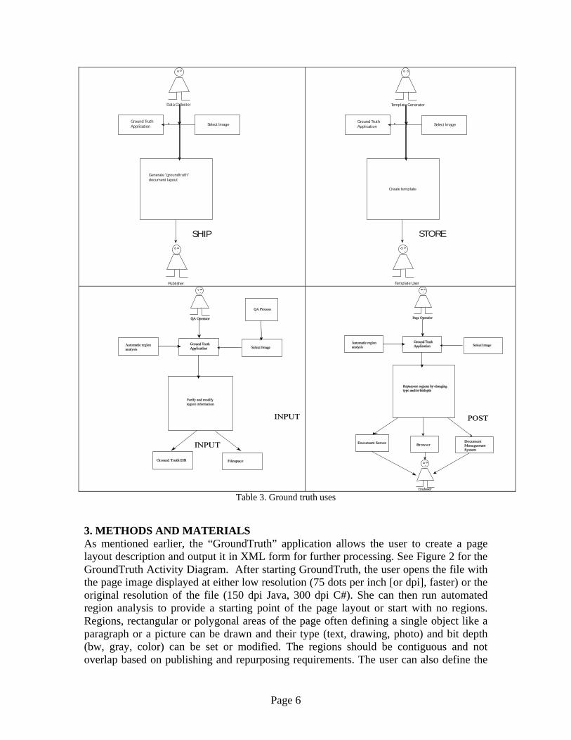
Table 1. Sample results (from > 4000 pages) from AutoQA feedback (closed loop) Forms, templates, specialized scanning adapters, and specific re-purposing applications (i.e. for print-on-demand, web page generation, content delivery to specialized display devices, etc.) require 100% accuracy for layout definition. A 100% accurate description of a document/image/etc. layout is termed “ground truth”. Ground truth specifies exactly where all of the regions on a (possibly composite) image are. It also describes what they are (e.g. “text”, “photo”, “drawing” or even more specialized layout elements such as “header”, “footnote”, “photo credit”, “bulleted list” or “background color”), termed “region type”. Furthermore, it may describe how the region is to be treated (e.g. as binary “BW”, or black & white; “GRAY” or 8-bit typically, and “COLOR” or 24-bit typically), termed “modality”. Ground truthing can be used to ensure proper rendering of a complex scanned document (e.g. to a print- or publishing-related destination such as .PDF, .DOC, .RTF formats). It can also be used to define web page specifications (e.g. .HTML, .XML formats). In defining a template for all other documents in a set, Ground Truth can be used for forms processing, for specialized scanning adapters, such as slides, photo and transparency adapters. These ground truth uses are shown in Table 2: While automated QA techniques provide us with as high as a 99.5% success rate, the remaining 0.5% has to be processed manually. On our more than 1.2 million-page corpus, this turns out to be more than 6,000 pages that have to be looked at by a human operator. Another 1-2% may be necessary to process manually based on the visual appearance of the reconstructed (output) document. These are pages that pass Auto QA but have some (usually small or subtle) visual defect (Visual QA). Such defects include rendering photos in 1-bit and rendering line drawings in grayscale (8-bit). Most are binarization/gray issues, since lost regions and segmentation errors are mainly captured by AutoQA. This means more than 30,000 corpus pages in our set will have to be reviewed with the GroundTruth application. Of course, given different sizes and complexities of corpuses, these percentages and values will differ. Our goal is to limit the review process to 2 pages/minute (the authors, after a few training pages, achieved a throughput of 5 pages/minute). This means our pages could be processed in 15,000 man-minutes (6.25 man-weeks). If this corpus is representative, the manual rate is 1.2 million/ 6.25 pages/week/man or 200, 000 pages/man-week.
Page 3

Purpose Action Description QA Proofing Input This is the original purpose for the ground truth application.
Automatic region generation can generate substantial quantities (up to 2.5% in the case of our document corpus) of incorrectly processed documents. The QA Operator processes each of the incorrect images by verifying and modifying auto generated areas of interest to create metadata description of document page layout. This information can be then combined with the image data to generate the new PDF description of the page.
Template Generation
Store The metadata information extracted from an image can be used as a template for page layout, allowing efficient page storage. Due to the possibility of page scan errors and also some variations in printing the template, the layout might have to be adjusted to generate info for a specific page. The Ground Truth-type application is used to either generate the template, or modify an existing template to a specific image. Only the modified metadata would have to be stored.
Ground truth Definition
Ship Once there is a way to extract areas of interest on a page, those areas can be processed to extract a specific metadata required by the end user. For example, in our project the region information can be combined with the original image and test information extracted by optical character recognition to produce a searchable page in a PDF format that can be provided to a publisher for digital publishing.
Repurposing Post Use of metadata for page description allows us to present the same document in a variety of ways just by changing the region description. For example a change of the bit depth for photo regions can make them more suitable for different media and/or printers. Publishing to print, web or storage can be easily accomplished.
Table 2. Uses for the Ground Truthing Engine
The application (GroundTruth) was written to graphically specify page layout and then generate an XML description of the page. The two engineers involved in the project predominantly develop on two different development platforms – Java and C++. We decided that it would be interesting to use this project to examine the new Visual Studio.NET and C# environment and compare it to the more mature Java platform. GroundTruth is not necessarily a shining example of the type of software for which Java or .NET would be picked. No web or database components are needed, and portability is not a crucial issue (although a preference for UNIX by the end-user was one argument for the initial deployment in Java). Because of the .NET OS requirements, our end-user environment was a Windows 2000 system. The Mono project (http://www.go-mono.com) should provide an open source Linux .NET implementation in the near future.
Page 4

AnalysisForceManhattanRegions()mitprocess -rects -o outdir indir
START
AnalysisForceRectangularPageRegion()mitprocess -1bw -0 outdir indir
AnalysisForceManhattanTextAndGrayRegions()mitprocess -rectgray -0 outdir indir
AnalysisNew()AnalysisAlterRegionPresentationAfterZoning()
mitprocess -0 outdir indir
Use GroundTruthing Applicationon File to input desired regions via an XML file
mitprocess -gtxml -0 outdir indir
PassesAutoQA?
PassesAutoQA?
PassesAutoQA?
PassesAutoQA?
STOP
NO
NO
NO
NO
YES
YES
YES
YES
AnalysisForceGrayRectangularPageRegion()mitprocess -1gray -0 outdir indir
PassesAutoQA?
YES
NO
Figure 1. QA Process
Page 5
Data Collector
Generate "groundtruth" document layout
Ground Truth Application Select Image
Publisher
SHIP
Template Generator
Create template
Ground Truth Application Select Image
Template User
STORE
Table 3. Ground truth uses 3. METHODS AND MATERIALS As mentioned earlier, the “GroundTruth” application allows the user to create a page layout description and output it in XML form for further processing. See Figure 2 for the GroundTruth Activity Diagram. After starting GroundTruth, the user opens the file with the page image displayed at either low resolution (75 dots per inch [or dpi], faster) or the original resolution of the file (150 dpi Java, 300 dpi C#). She can then run automated region analysis to provide a starting point of the page layout or start with no regions. Regions, rectangular or polygonal areas of the page often defining a single object like a paragraph or a picture can be drawn and their type (text, drawing, photo) and bit depth (bw, gray, color) can be set or modified. The regions should be contiguous and not overlap based on publishing and repurposing requirements. The user can also define the
Page 6
visible area, which is the smallest rectangle containing all the regions and whatever border around them is also preferred. This is automatically updated to include at least a border of 0 as new regions are added (no negative borders allowed). Prompt UI feedback is necessary for ease-of use and speed of page processing. After all, we should minimize the amount of time the operator spends on each page. Regions should be color-coded for easy, at-a-glance, identification of regions. Standard techniques like rubberbanding should be used for region definition. Context menus (right-clicking) can be easily used for modification of attributes. Once the user is satisfied with the region placement and properties the page description can be saved in an XML format. See XML Section for corresponding dtd. One possible output for the Moose Picture (See Figure 4) is shown in the same section. The metadata generated is sufficient to reproduce the intended layout or reuse it on similar pages as a template. 4. APPLICATION OVERVIEW 4.1. C# Version The C# version of Ground Truth (See Figure 5) application uses the single document model to separate the UI from the application data. All information necessary to output XML data is stored in the GroundTruthDoc class (See Figure 3). This includes the information about the output resolution and an array of regions currently defined on the page. To output the XML information we used .NET’s XML serialization to output the document class. This class also provides region management, making sure that new regions do not overlap old ones and that any new polygon is convex. The automatic region analysis is performed by a legacy C++ DLL. Unfortunately, we cannot directly call its functions from C#. We have created a separate managed C++ DLL that is used to marshal the image information and the resulting region data. This is similar to wrapping API functions using JNI in Java. We will describe this in greater detail below. For drawing support we use the new GDI+, which created some interesting problems – the biggest one being no XOR drawing support. 4.2. Java Version The Java version of the Ground Truth application (See Figure 6) differs from the C# version. Rather than using a large (100k lines of code) legacy C++-native zoning analysis engine (as implemented for the C# application), it uses a smaller native Java zoning analysis engine (20k lines of code) that does not allow overlapping regions. This Java engine was co-developed in C++ for performance comparison (without JIT compiling, the performance was approximately 25% better in native C++ than in Java when running on a Windows 2000 Pentium 4 portable); however, the larger legacy engine was chosen for the C# application as it had better overall zoning accuracy (e.g. it
Page 7

had a mean error rate in segmentation/classification of <0.1% compared to 0.2% for the smaller, 20k lines of code, engine). For imaging support, the Java Advanced Imaging (JAI), version 1_1_1 (http://java.sun.com/products/java-media/jai/index.html), was used. It provides full support of the TIFF directory, and is also useful on BMP input files (Windows), although it provides sparse metadata information for JPEG and GIF files (i.e. resolution is not provided). For the latter file formats, the user may have had to manually enter (e.g. into a file containing defaults) the x and y resolutions of the original document. A simple rubberbanding class was generated which took advantage of the XOR capabilities of the Java graphics package; e.g.: Import java.awt.*; … Graphics g = component.getGraphics();
if(g != null) { try { g.setXORMode(component.getBackground());
… } 5. CHOOSING UI TOOLS 5.1 C# Version The UI in Ground Truth (See Figure 5) was created in Visual Studio .NET. This is where there is a considerable difference between programming C++ with MFC and C#. Unlike in VS 6, in VS.NET you design your UI graphically with a Forms-based interface. While for a C++ programmer the interface would require some getting used to, for a Visual Basic programmer it is a familiar approach. As you design the layout you drag and drop the controls on the form and change their properties and events in property sheets. The corresponding C# code is generated automatically. It’s quite slick. It is very important, though, to follow the warnings about code modification in the automatically generated comments. Additions in the middle of “Window Form Designer generated code” can make your form unloadable, and what is more alarming, it can cause the compiler to crash. The areas for addition of your own code are clearly marked with comments. There is some tradeoff between ease of use vs. flexibility whenever using the automated tools. Fortunately, handcrafted UI pieces can be also created. In our case the main region definition area is a handcrafted control inheriting from a Picture Box. The drawing in C# is done with GDI+. It is the new interface that shows up with .NET, but unfortunately it is not yet ready for prime time. One of the big issues we ran into was lack of ability to do XOR drawing, which makes rubberbanding rather unpleasant. To get around it we had to create a new rubberbanding class that copies parts of the screen image and bitblits it back to the screen as needed. This is definitely a slower approach that can cause delays in drawing smoothness.
Page 8

5.2 Java Version Many form editors exist in various Java IDEs. Forte Internet Edition was used to develop & test the Java version of the GroundTruth application, and the UI components were readily created using the Form Editor for GUI tools in Forte that “create JFC (Swing) forms that can be designed visually”. Except for the rubberbanding class (which can be modified from any one of several examples on the web: http://www.apl.jhu.edu/~hall/CWP-Sources/CWP-Examples/Chapter14/1.1/Rubberband.java is a good starting point), most UI tools were readily hooked to the menus, right clicks, hotkeys, and other activation methods. Forte CE (Community Edition), of course, is fine for this task, and is available without charge at http://java.sun.com/j2se/1.4/download.html (Forte is now called the SunTM ONE Studio). 6. NATIVE CODE INTEGRATION Unlike the Java version, the C# version of Ground Truth required integration of a legacy DLL that provides the analysis support. The analysis DLL takes a bitmap image (preferably at lower resolution) and returns location and classification of areas of interest on the page. Because the code is written in unmanaged C++, it required us to provide marshaling of data across the code boundaries. To assist us, we created a managed C++ object to do the actual marshaling and invoke the legacy code. While there is an implementation of GDI+ in C++, we found that it does not work very well across mixed languages. Passing Image data from C# to managed C++ caused crashes in ATL. In the end we had to revert to old Windows basics. For our image we extracted the corresponding HBITMAP handle and passed it to managed C++. There the new Image structure is created from the HBITMAP. Once we had the image, we could allocate unmanaged (__nogc) memory for the pixel data, copy it and invoke the legacy code. As a part of the Analysis DLL we create two managed classes that can be then accessed from the C# code: #pragma once #include "aiScanBedAnalysis.h" #include "aiScanBedRegion.h" #include "afxcoll.h" using namespace System; namespace Analysis_DLL { public __value class Pt { public: int x; int y; }; // Analysis Region converts unmanaged ScanBedRegion to a managed object public __gc class AnalysisRegion {
Page 9

public: __value enum RegionType { JUNK = 0, TEXT = 1, PHOTO = 2, DRAWING = 3, HANDWRITING = 4, CARTOON = 5, TABLE = 6, GRAPH = 7, BUSINESSGRAPHIC = 8, BACKGROUND = 9, EQUATION = 10, COMPOSITETEXT = 11 }; __value enum RegionModality { BW =0, GRAY = 1, COLOR =2 }; AnalysisRegion( int RegNum, ScanBedAnalysis *Analysis); Pt GetData()[] {return RegPolygon;} RegionType GetRegType(){ return RegType;} Pt GetPoint( int i ) {return RegPolygon[i];} int PtCount() {return PointCount;} RegionModality GetRegModality() {return RegModality;} private: Pt BBox; int BBox_height; int BBox_width; Pt RegPolygon[]; RegionType RegType; RegionModality RegModality; int IsColor; int PointCount; }; //wrapper around AnalysisAPI, marshals image data. public __gc class AnalysisDllAPI { public: AnalysisDllAPI(); static ScanBedAnalysis *m_pScanBedAnalysisEngine; int InternalizeScannerData( System::IntPtr Bmp, int Resolution ); //int InternalizeScannerData( const __gc CImage *Bmp, int Resolution ); int AnalysisNew(); int RegionCount(); AnalysisRegion *GetRegion(int index);
Page 10
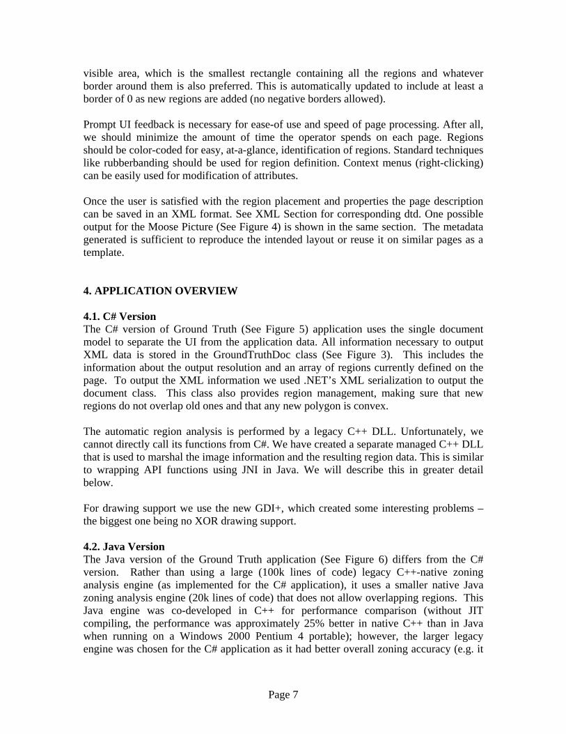
}; } The AnalysisDllAPI does the image marshaling, allocating the unmanaged memory and copying the actual image data. The AnalysisRegion class marshals the region information from analysis to a form accessible by C#. #include "StdAfx.h" #include <atlstr.h> #include <atlimage.h> #include "analysisdllapi.h" using namespace Analysis_DLL; AnalysisDllAPI::AnalysisDllAPI(void) { System::Console::WriteLine("Analysis Api"); if (m_pScanBedAnalysisEngine) delete m_pScanBedAnalysisEngine; m_pScanBedAnalysisEngine = new ScanBedAnalysis; } int AnalysisDllAPI::InternalizeScannerData( System::IntPtr Bmp, int Resolution ) { IMAGE_MAP2* pMap = new IMAGE_MAP2; int Result = 0; unsigned char *data; unsigned char *input; pMap->hImage = NULL; pMap->Address = NULL; pMap->CTable = NULL; CImage bmp; bmp.Attach((HBITMAP)Bmp.ToInt32()); int width = bmp.GetWidth(); int height = bmp.GetHeight(); pMap->BitsPerPixel = 24; pMap->Height = height; pMap->Width = width; pMap->BytesPerLine = width * 3; pMap->XResolution = Resolution; pMap->YResolution = Resolution; pMap->Type = IM_RGB; input = (unsigned char *)bmp.GetBits(); data = new unsigned char[height * width *3]; for ( int i =0; i <height; i++ ) { for ( int j = 0; j < width; j++ ) { COLORREF col = bmp.GetPixel(j,i); data[i*pMap->BytesPerLine+3*j] = GetRValue( col ); data[i*pMap->BytesPerLine+3*j+1] = GetGValue( col ); data[i*pMap->BytesPerLine+3*j+2] = GetBValue( col ); }
Page 11
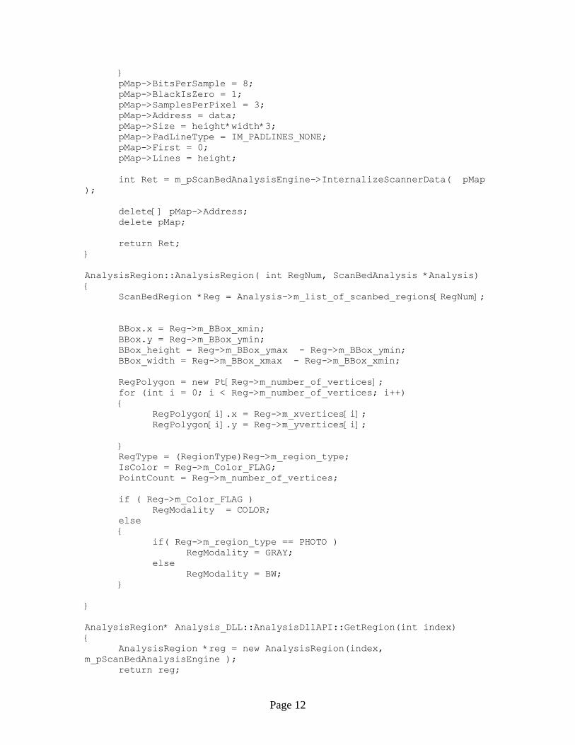
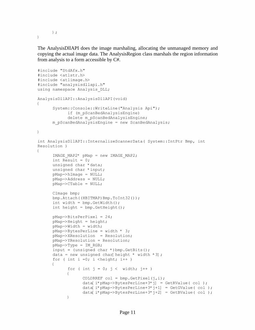
} pMap->BitsPerSample = 8; pMap->BlackIsZero = 1; pMap->SamplesPerPixel = 3; pMap->Address = data; pMap->Size = height*width*3; pMap->PadLineType = IM_PADLINES_NONE; pMap->First = 0; pMap->Lines = height; int Ret = m_pScanBedAnalysisEngine->InternalizeScannerData( pMap ); delete[] pMap->Address; delete pMap; return Ret; } AnalysisRegion::AnalysisRegion( int RegNum, ScanBedAnalysis *Analysis) { ScanBedRegion *Reg = Analysis->m_list_of_scanbed_regions[RegNum]; BBox.x = Reg->m_BBox_xmin; BBox.y = Reg->m_BBox_ymin; BBox_height = Reg->m_BBox_ymax - Reg->m_BBox_ymin; BBox_width = Reg->m_BBox_xmax - Reg->m_BBox_xmin; RegPolygon = new Pt[Reg->m_number_of_vertices]; for (int i = 0; i < Reg->m_number_of_vertices; i++) { RegPolygon[i].x = Reg->m_xvertices[i]; RegPolygon[i].y = Reg->m_yvertices[i]; } RegType = (RegionType)Reg->m_region_type; IsColor = Reg->m_Color_FLAG; PointCount = Reg->m_number_of_vertices; if ( Reg->m_Color_FLAG ) RegModality = COLOR; else { if( Reg->m_region_type == PHOTO ) RegModality = GRAY; else RegModality = BW; } } AnalysisRegion* Analysis_DLL::AnalysisDllAPI::GetRegion(int index) { AnalysisRegion *reg = new AnalysisRegion(index, m_pScanBedAnalysisEngine ); return reg;
Page 12
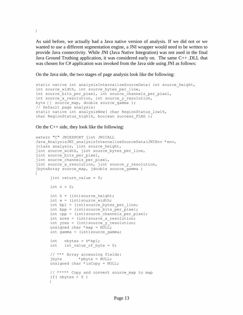
} As said before, we actually had a Java native version of analysis. If we did not or we wanted to use a different segmentation engine, a JNI wrapper would need to be written to provide Java connectivity. While JNI (Java Native Integration) was not used in the final Java Ground Truthing application, it was considered early on. The same C++ .DLL that was chosen for C# application was invoked from the Java side using JNI as follows: On the Java side, the two stages of page analysis look like the following: static native int analysisInternalizeSourceData( int source_height, int source_width, int source_bytes_per_line, int source_bits_per_pixel, int source_channels_per_pixel, int source_x_resolution, int source_y_resolution, byte [] source_map, double source_gamma ); // Default page analysis: static native int analysisNew( char RegionStatus_low16, char RegionStatus_high16, boolean success_FLAG ); On the C++ side, they look like the following: extern "C" JNIEXPORT jint JNICALL Java_AnalysisJNI_analysisInternalizeSourceData(JNIEnv *env, jclass analysis, jint source_height, jint source_width, jint source_bytes_per_line, jint source_bits_per_pixel, jint source_channels_per_pixel, jint source_x_resolution, jint source_y_resolution, jbyteArray source_map, jdouble source_gamma ) { jint return_value = 0; int n = 0; int h = (int)source_height; int w = (int)source_width; int bpl = (int)source_bytes_per_line; int bpp = (int)source_bits_per_pixel; int cpp = (int)source_channels_per_pixel; int xres = (int)source_x_resolution; int yres = (int)source_y_resolution; unsigned char *map = NULL; int gamma = (int)source_gamma; int nbytes = h*bpl; int int_value_of_byte = 0; // *** Array accessing fields: jbyte *pbyte = NULL; unsigned char *isCopy = NULL; // ***** Copy and convert source_map to map if( nbytes > 0 ) {
Page 13

map = new unsigned char[ nbytes ]; if( map == NULL ) return( MEMORY_ALLOCATION_ERROR ); pbyte = env->GetByteArrayElements( source_map, isCopy ); // JNI call to access the jbyte array--isCopy is a // jboolean that is filled with JNI_TRUE if a copy // is made; with JNI_FALSE otherwise if( pbyte == NULL ) return( MEMORY_ALLOCATION_ERROR ); // Experimentally-driven mapping for( n=0; n<nbytes; n++ ) { int_value_of_byte = (int)pbyte[n]; if( int_value_of_byte >= 0 ) map[n] = (unsigned char)int_value_of_byte; // 0...127 in C++ unsigned char are mapped to // 0...127 in Java byte else map[n]=(unsigned char)(256+int_value_of_byte); // 128...255 in C++ unsigned char are mapped to // -128...-1 in Java byte } env->ReleaseByteArrayElements( source_map, pbyte, 0 ); // JNI call to release the jbyte array--mode "0" is // used to free the pbyte buffer after updating // the source_map elements } // ********** Internalize the Scanner Data return_value = scanbed_analysis.InternalizeScannerData( h, w, bpl, bpp, cpp, xres, yres, map, gamma ); // *** Clean up memory if( map != NULL ) { delete [] map; map = NULL; } return return_value; } extern "C" JNIEXPORT jint JNICALL Java_AnalysisJNI_analysisNew__CCZ( JNIEnv *env, jclass analysis, jchar RegionStatus_low16, jchar RegionStatus_high16, jboolean success_FLAG ) { jint return_value = 0; bool successFLAG = TRUE; UINT32 RegionStatusWord = (UINT32)RegionStatus_low16; UINT32 temp = (UINT32)RegionStatus_high16; RegionStatusWord += (temp<<16); if( success_FLAG == FALSE )
Page 14
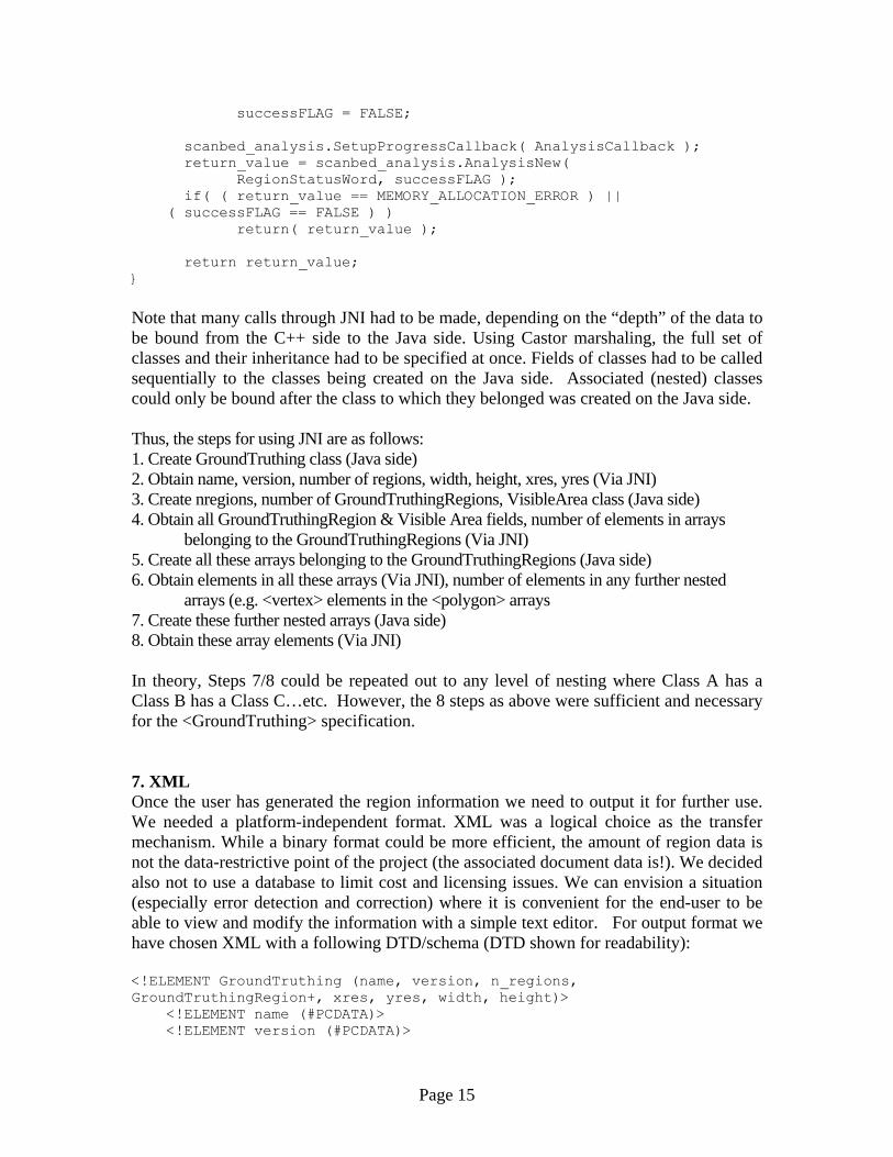
successFLAG = FALSE; scanbed_analysis.SetupProgressCallback( AnalysisCallback ); return_value = scanbed_analysis.AnalysisNew( RegionStatusWord, successFLAG ); if( ( return_value == MEMORY_ALLOCATION_ERROR ) || ( successFLAG == FALSE ) ) return( return_value ); return return_value; } Note that many calls through JNI had to be made, depending on the “depth” of the data to be bound from the C++ side to the Java side. Using Castor marshaling, the full set of classes and their inheritance had to be specified at once. Fields of classes had to be called sequentially to the classes being created on the Java side. Associated (nested) classes could only be bound after the class to which they belonged was created on the Java side. Thus, the steps for using JNI are as follows: 1. Create GroundTruthing class (Java side) 2. Obtain name, version, number of regions, width, height, xres, yres (Via JNI) 3. Create nregions, number of GroundTruthingRegions, VisibleArea class (Java side) 4. Obtain all GroundTruthingRegion & Visible Area fields, number of elements in arrays
belonging to the GroundTruthingRegions (Via JNI) 5. Create all these arrays belonging to the GroundTruthingRegions (Java side) 6. Obtain elements in all these arrays (Via JNI), number of elements in any further nested
arrays (e.g. <vertex> elements in the <polygon> arrays 7. Create these further nested arrays (Java side) 8. Obtain these array elements (Via JNI) In theory, Steps 7/8 could be repeated out to any level of nesting where Class A has a Class B has a Class C…etc. However, the 8 steps as above were sufficient and necessary for the <GroundTruthing> specification. 7. XML Once the user has generated the region information we need to output it for further use. We needed a platform-independent format. XML was a logical choice as the transfer mechanism. While a binary format could be more efficient, the amount of region data is not the data-restrictive point of the project (the associated document data is!). We decided also not to use a database to limit cost and licensing issues. We can envision a situation (especially error detection and correction) where it is convenient for the end-user to be able to view and modify the information with a simple text editor. For output format we have chosen XML with a following DTD/schema (DTD shown for readability): <!ELEMENT GroundTruthing (name, version, n_regions, GroundTruthingRegion+, xres, yres, width, height)> <!ELEMENT name (#PCDATA)> <!ELEMENT version (#PCDATA)>
Page 15
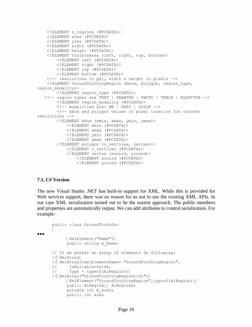
<!ELEMENT n_regions (#PCDATA)> <!ELEMENT xres (#PCDATA)> <!ELEMENT yres (#PCDATA)> <!ELEMENT width (#PCDATA)> <!ELEMENT height (#PCDATA)> <!ELEMENT VisibleArea (left, right, top, bottom)> <!ELEMENT left (#PCDATA)> <!ELEMENT right (#PCDATA)> <!ELEMENT top (#PCDATA)> <!ELEMENT bottom (#PCDATA)> <!-- resolutions in ppi, width & height in pixels --> <!ELEMENT GroundTruthingRegion (bbox, polygon, region_type, region_modality)> <!ELEMENT region_type (#PCDATA)> <!-- region types are TEXT | DRAWING | PHOTO | TABLE | EQUATION --> <!ELEMENT region_modality (#PCDATA)> <!-- modalities are: BW | GRAY | COLOR --> <!-- bbox and polygon values in pixel location for current resolutions --> <!ELEMENT bbox (xmin, xmax, ymin, ymax)> <!ELEMENT xmin (#PCDATA)> <!ELEMENT xmax (#PCDATA)> <!ELEMENT ymin (#PCDATA)> <!ELEMENT ymax (#PCDATA)> <!ELEMENT polygon (n_vertices, vertex+)> <!ELEMENT n_vertices (#PCDATA)> <!ELEMENT vertex (xcoord, ycoord)> <!ELEMENT xcoord (#PCDATA)> <!ELEMENT ycoord (#PCDATA)> 7.1. C# Version The new Visual Studio .NET has built-in support for XML. While this is provided for Web services support, there was no reason for us not to use the existing XML APIs. In our case XML serialization turned out to be the easiest approach. The public members and properties are automatically output. We can add attributes to control serialization. For example: public class GroundTruthDoc { ●●● [XmlElement("Name")] public string m_Name; // If we prefer an array of elements do following: //[XmlArray] //[XmlArrayItem(ElementName= "GroundTruthingRegion", // IsNullable=false, // Type = typeof(AiRegion))] //[XmlArray("GroundTruthingRegionList")] [XmlElement("GroundTruthingRegion",typeof(AiRegion))] public AiRegion[] AiRegions; private int m_xres; public int xres
Page 16
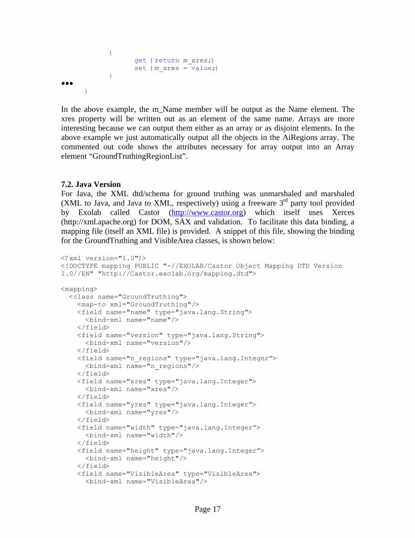
{ get {return m_xres;} set {m_xres = value;} } ●●●
} In the above example, the m_Name member will be output as the Name element. The xres property will be written out as an element of the same name. Arrays are more interesting because we can output them either as an array or as disjoint elements. In the above example we just automatically output all the objects in the AiRegions array. The commented out code shows the attributes necessary for array output into an Array element “GroundTruthingRegionList”. 7.2. Java Version For Java, the XML dtd/schema for ground truthing was unmarshaled and marshaled (XML to Java, and Java to XML, respectively) using a freeware 3rd party tool provided by Exolab called Castor (http://www.castor.org) which itself uses Xerces (http://xml.apache.org) for DOM, SAX and validation. To facilitate this data binding, a mapping file (itself an XML file) is provided. A snippet of this file, showing the binding for the GroundTruthing and VisibleArea classes, is shown below: <?xml version="1.0"?> <!DOCTYPE mapping PUBLIC "-//EXOLAB/Castor Object Mapping DTD Version 1.0//EN" "http://Castor.exolab.org/mapping.dtd"> <mapping> <class name="GroundTruthing"> <map-to xml="GroundTruthing"/> <field name="name" type="java.lang.String"> <bind-xml name="name"/> </field> <field name="version" type="java.lang.String"> <bind-xml name="version"/> </field> <field name="n_regions" type="java.lang.Integer”> <bind-xml name="n_regions"/> </field> <field name="xres" type="java.lang.Integer"> <bind-xml name="xres"/> </field> <field name="yres" type="java.lang.Integer”> <bind-xml name="yres"/> </field> <field name="width" type="java.lang.Integer”> <bind-xml name="width"/> </field> <field name="height" type="java.lang.Integer”> <bind-xml name="height"/> </field> <field name="VisibleArea" type="VisibleArea"> <bind-xml name="VisibleArea"/>
Page 17

</field> <field name="GroundTruthingRegions" type="GroundTruthingRegion" collection="vector"> <bind-xml name="GroundTruthingRegion"/> </field> </class> <class name="VisibleArea"> <map-to xml="VisibleArea"/> <field name="left" type="java.lang.Integer”> <bind-xml name="left"/> </field> <field name="right" type="java.lang.Integer”> <bind-xml name="right"/> </field> <field name="top" type="java.lang.Integer”> <bind-xml name="top"/> </field> <field name="bottom" type="java.lang.Integer”> <bind-xml name="bottom"/> </field> </class> <!—GroundTruthingRegion and its associated classes here--> </mapping> The output for the moose file may look like this: <GroundTruthing> <name>Ground Truthing Engine in JAVA</name> <version>1.0</version> <n_regions>1</n_regions> <xres>75</xres> <yres>75</yres> <width>638</width> <height>875</height> <VisibleArea> <left>0</left> <right>638</right> <top>0</top> <bottom>825</bottom> </VisibleArea> <GroundTruthingRegion> <region_type>PHOTO</region_type> <region_modality>BW</region_modality> <bbox> <xmin>329</xmin> <xmax>593</xmax> <ymin>45</ymin> <ymax>412</ymax> </bbox> <polygon> <n_vertices>5</n_vertices> <vertex> <xcoord>329</xcoord> <ycoord>412</ycoord>
Page 18

</vertex> <vertex> <xcoord>593</xcoord> <ycoord>412</ycoord> </vertex> <vertex> <xcoord>593</xcoord> <ycoord>45</ycoord> </vertex> <vertex> <xcoord>329</xcoord> <ycoord>45</ycoord> </vertex> <vertex> <xcoord>329</xcoord> <ycoord>412</ycoord> </vertex> </polygon> </GroundTruthingRegion> </GroundTruthing> 8. DISCUSSION Part of this exercise was to compare C# and Java programming in a practical environment rather than comparing language features. As with most projects the major factors were: 1. End platform requirement 2. Feature set & robustness 3. Developer preference 8.1. End Platform Requirement In the current incarnation the use of C# is limited to Windows systems. With heterogeneous or non-Windows requirements, Java will be a better choice. Once the Mono project finishes (based on the specification that Microsoft submitted to ECMA) with its open source version of .NET, portability may become a lesser issue. In desktop-type GUI applications, C# can be a reasonable choice due to the ease of GUI design and the prevalence of Windows on the desktop. VisualStudio .NET makes the design of Windows look-and-feel simple with easy access to standard Microsoft controls. Note that Java applications are readily rendered with a Window’s look-and-feel. Corporate culture and budget should be also taken into consideration. The .NET environment is feature rich without necessarily turning to 3rd party tools. In places that have something (like possible legal reprisals!) against using Open Source tools the cost of Java use might become prohibitive in programming time or cost for commercial tools. Often integration costs will outstrip the software cost in large-scale projects. 8.2. Feature Set and Robustness Because Java has been out for several years, and is well-adopted in the programming community, there are large amount of tools and libraries both commercial and free to help with most specialized areas. In our case the Castor project allowed us access to
Page 19

XML without heavy coding of object serialization to XML. Also over time the number of tools available on main Java distribution is increasing. For example, Java 1.4 has now javax.imageio with jpg, gif and png support. JAI needs to be used only for tiff and bmp. The .NET environment is unexpectedly feature rich. We assumed that some features like large number of image formats will not be available to us. Surprisingly they were available. On the other hand, some rudimentary features like XOR drawing were inexplicably not present causing us delays while we create workarounds. Java and Forte( now Sun ONE) provides a very stable environment. A huge free and share community exists for Java & Forte developers. The same can’t be said for the VisualStudio .NET environment. While the C# was very well behaved (as long as we followed Microsoft warnings about not touching automatically generated code) the integration of other languages on the top of CLR (Common Language Runtime) left much to be desired. The managed C++ did not interoperate well with C# and we gave up trying to pass Image objects. 8.3. Developer Preferences Finally, developer preferences and training should be taken in to consideration. In our case, neither one of us was convinced enough to change our development language preference. At this point, if integration of large amount of legacy code is necessary, C++ should be seriously considered. Integration of managed and unmanaged code can be awkward and time-consuming, depending on the number of entry points in the legacy code. C#, like Java, is a pleasant language to program in, but at this point we recommend it only if all of the necessary components are available in a managed form. 8.4. Final Thoughts In addition to its intended purpose as a proofing tool for a print-on-demand service, the GroundTruth application has other valuable applications for HP’s capture, printing and publishing businesses. In defining a template, the application can be used to “ignore” regions not defined by the user, and so, for example, it can be used to capture only the images off of slide adapters (capture), or only the germane parts of a large document (such as headers, titles, etc.) for printing and/or publishing. Additionally, in specifying exactly the zoning region types and modalities, it is an invaluable tool for layout definition, description, and re-purposing.
Page 20

Chart ID : GT Activity Chart Name : GT ActivityChart Type : UML Activity DiagramChart Stereotype : «Activity Diagram»
Region Edit
Start
Load Image
Analysis
Add regions
Output XML
Edit Regions
Branch
Merge
[not all regions specified] [not all regions correct][else]
[not all regions correct]
[automatic region generation] [else]
Activity Diagram: GT Activity
Figure 2. Ground Truth Activity Diagram
Page 21

+GroundTruth::GroundTruthDoc
Regions: ArrayList +m_Name: string +version: string +region_count: int +xres: int +yres: int +width: int +height: int +Mode: RegMode +AiRegions: AiRegion[] +PageFileName: string Analysis: Analysis_dll.AnalysisDllAPI «Constructor» +GroundTruthDoc( ) +SetFile(FileName: string): void +DoAnalysis(Bmp: System.Drawing.Bitmap, Resolution: Double): void+AddRegion(reg: AiRegion): void +Find(reg: Region): int +Find(pt: Point): int +GetRegions( ): ArrayList +SaveXml(FileName: string): int
+XValuesOfScanLineSegments(pyrange: int [], yrange: int, ymin: int, poly_data: ai_polygon, num_vertices: int, xvalues: int [], num_xvalues: int): int
+GroundTruth::AiRegion$Region_Name: string[] $Region_Modality: string[] poly: ai_polygon gp: GraphicsPath start_line: Point begining: Point BBox: bbox m_height: int m_width: int m_return_value: int m_n_xcoordinates: int m_xcoordinates: int[] m_pyrange: int[] used: bool type: Analysis_dll.AnalysisRegion.RegionType +region_type: String points: ArrayList «Property» +polygon( ): ai_polygon «Constructor» +AiRegion( ) «Constructor» +AiRegion(reg: AnalysisRegion) +Close( ): void +Add(pt: Point, end: bool): void +Add(UL: Point, LR: Point): void +Contains(pt: Point): bool +SetType(t: Analysis_dll.AnalysisRegion.RegionType): void+Draw(dc: Graphics, Scale: double): void +CreateScanLineSegments(h: int, w: int): int +NumberOfScanLineSegments(pyrange: int [], yrange: int, ymin: int, poly_data: ai_polygon, num_vertices: int): int
+SortXValuesOfScanLineSegments(pyrange: int [], yrange: int, xvalues: int []): int+IsIntersecting(p1: Point, p2: Point): bool
+GroundTruth::ai_polygon -verts: vertex[] +n_vertices: int «Property» +vertices( ): vertex[] «Constructor» +ai_polygon( ) +Add(v: vertex): void
+Intersects(poly:ai_polygon): bool +IsConcave(): bool
Figure 3. GroundTruthDoc UML
Page 22

Figure 4. Moose picture
Page 23

Figure 5. C# UI
Page 24
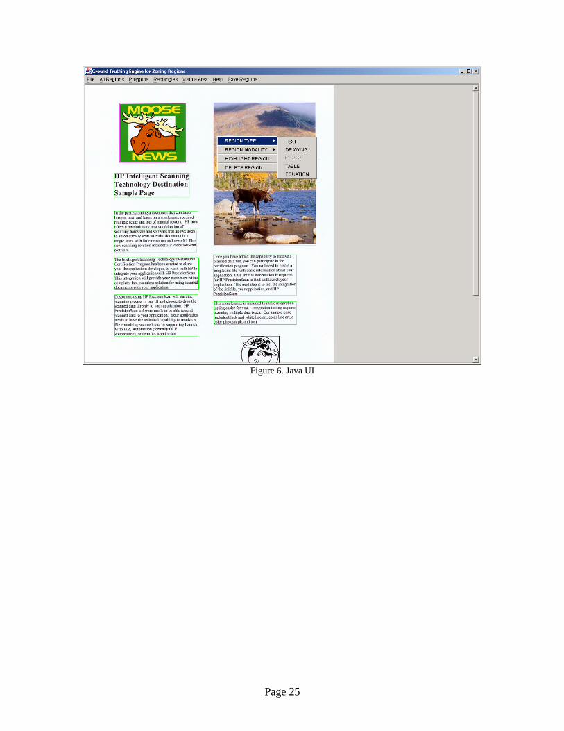
Figure 6. Java UI
Page 25