a qos framework for connection services in parlay · the qos functionality of connection services...
TRANSCRIPT
A QoS Framework for
Connection Services in Parlay
Yusuf Bata
A research report submitted to the Faculty of Engineering and the Built Environment,
University of the Witwatersrand, Johannesburg, in partial fulfilment of the requirements for
the degree of Master of Science in Engineering.
Johannesburg, December 2006
i
Declaration
I declare that this research report is my own, unaided work, except where otherwise ac-
knowledged. It is being submitted for the degree of Master of Science in Engineering to the
University of the Witwatersrand, Johannesburg. It has not been submitted before for any
degree or examination in any other university.
Signed this day of 20
Yusuf Bata.
ii
Abstract
Most applications using network connection services require information to be transferred
within specific constraints (or Quality of Service). Parlay enables applications to access
functionality of underlying networks while preserving network integrity. Connection service
functionality of underlying networks is currently provided to applications by Parlay in the
Call Control and Data Session Control SCFs. Parlay does not however provide access to
the QoS functionality of connection services although this functionality may be provided by
networks. This report presents the design, specification and simulation of a QoS framework
for connection services provided by Parlay. The QoS framework provides applications with
access to the QoS functionality of connection services in the underlying networks. The de-
sign is divided into 3 parts (or models): the object model (defines the objects that make up
the QoS framework), the information model (deals with how objects specify QoS and map-
pings between different QoS specifications), and the interaction model (defines how objects
interact). A formal, technology-independent specification of the QoS framework is presented
using UML. The specification is composed using the three parts of the design. A simulation
of the QoS framework presented in this report is also described to validate the framework.
The simulation is a multi-threaded, distributed CORBA application implemented in JAVA
(Java SDK version 1.5) and is based on the UML specification of the QoS framework. Details
about the simulation design and implementation are summarised in this report. The QoS
framework provides per-application, per-connection QoS support for Parlay’s connection ser-
vices, supports existing and future Parlay connection services, follows existing Parlay design
paradigms, and co-exists with and makes use of existing and future Parlay infrastructure.
Parlay guidelines relating to permitted changes are followed strictly in the design of the QoS
framework, which ensures the backward compatibility of Parlay if the QoS framework is
added to the Parlay API. All Parlay design guidelines are also followed to allow for the easy
integration of the QoS framework into the Parlay API. The simulation validates that the
design of the QoS framework is: complete (in terms of specification), realistic, compatible
with a standard Parlay implementation (JAVA and CORBA), and scalable (easy integration
of new connection services).
iii
Acknowledgements
I would like to thank my supervisor, Professor Hu Hanrahan, for his invaluable assistance
and guidance. I would also like to thank Telkom for granting me a bursary for which I am
truly grateful.
This work was performed in the Centre for Telecommunications Access and Services at
the University of the Witwatersrand. The Centre is funded by Telkom SA Limited, Siemens
Telecommunications, Sun Microsystems and the Department of Trade and Industry’s THRIP
programme. Their financial support is much appreciated.
Thank you to my parents and family for their never ending support, to my pillar of strength,
my loving wife, and to my newborn baby boy who brings unimaginable joy to my life.
Most importantly, all praises and thanks are due only to the Lord of all creation, without
whom nothing could ever be.
CONTENTS iv
Contents
Declaration i
Abstract ii
Acknowledgements iii
Contents iv
List of Figures xi
List of Tables xiv
1 Introduction 1
1.1 Background . . . . . . . . . . . . . . . . . . . . . . . . . . . . . . . . . . . . . 1
1.1.1 Connection Services . . . . . . . . . . . . . . . . . . . . . . . . . . . . 1
1.1.2 Quality of Service (QoS) . . . . . . . . . . . . . . . . . . . . . . . . . . 2
1.1.3 Parlay Overview . . . . . . . . . . . . . . . . . . . . . . . . . . . . . . 2
1.2 Problem Specification . . . . . . . . . . . . . . . . . . . . . . . . . . . . . . . 4
1.3 Scope of this Report . . . . . . . . . . . . . . . . . . . . . . . . . . . . . . . . 5
1.4 Document Overview . . . . . . . . . . . . . . . . . . . . . . . . . . . . . . . . 6
CONTENTS v
2 Connection Services 8
2.1 Introduction . . . . . . . . . . . . . . . . . . . . . . . . . . . . . . . . . . . . . 8
2.2 What is a Connection Service? . . . . . . . . . . . . . . . . . . . . . . . . . . 8
2.3 Entities that Make Up a System that Provides Connection Services . . . . . . 10
2.4 Using Connection Services . . . . . . . . . . . . . . . . . . . . . . . . . . . . . 10
2.5 Requirements from Connection Services . . . . . . . . . . . . . . . . . . . . . 10
2.6 QoS Components . . . . . . . . . . . . . . . . . . . . . . . . . . . . . . . . . . 11
2.6.1 QoS Specification . . . . . . . . . . . . . . . . . . . . . . . . . . . . . . 12
2.6.2 QoS Mechanisms . . . . . . . . . . . . . . . . . . . . . . . . . . . . . . 14
2.7 Conclusion . . . . . . . . . . . . . . . . . . . . . . . . . . . . . . . . . . . . . 15
3 An Analysis of Parlay 16
3.1 Introduction . . . . . . . . . . . . . . . . . . . . . . . . . . . . . . . . . . . . . 16
3.2 Connection Services in Parlay . . . . . . . . . . . . . . . . . . . . . . . . . . . 16
3.3 Entities in Parlay . . . . . . . . . . . . . . . . . . . . . . . . . . . . . . . . . . 18
3.4 Existing QoS Aspects in Parlay . . . . . . . . . . . . . . . . . . . . . . . . . . 19
3.4.1 Enterprise QoS Support (for Virtual Private Networks) . . . . . . . . 19
3.4.2 Definition of QoS Traffic Classes . . . . . . . . . . . . . . . . . . . . . 19
3.5 Changes Permitted to the Parlay API . . . . . . . . . . . . . . . . . . . . . . 21
3.5.1 Changes Permitted to the Parlay Gateway Side . . . . . . . . . . . . . 21
3.5.2 Changes Permitted to the Application Side . . . . . . . . . . . . . . . 21
3.5.3 Changes Permitted to Data Types . . . . . . . . . . . . . . . . . . . . 22
CONTENTS vi
3.6 Conclusion . . . . . . . . . . . . . . . . . . . . . . . . . . . . . . . . . . . . . 22
4 Design Requirements and Approach 23
4.1 Introduction . . . . . . . . . . . . . . . . . . . . . . . . . . . . . . . . . . . . . 23
4.2 System Analysis . . . . . . . . . . . . . . . . . . . . . . . . . . . . . . . . . . 23
4.3 Design Requirements . . . . . . . . . . . . . . . . . . . . . . . . . . . . . . . . 25
4.4 Design Overview . . . . . . . . . . . . . . . . . . . . . . . . . . . . . . . . . . 26
4.5 Analysis of QoS Framework Design . . . . . . . . . . . . . . . . . . . . . . . . 27
4.6 Summary of Design Influences . . . . . . . . . . . . . . . . . . . . . . . . . . . 28
4.6.1 The Quartz Architecture . . . . . . . . . . . . . . . . . . . . . . . . . 28
4.6.2 TINA Service Quality Features (SQFs) . . . . . . . . . . . . . . . . . 29
4.6.3 QoS Cycles . . . . . . . . . . . . . . . . . . . . . . . . . . . . . . . . . 30
4.6.4 The EQoS Framework . . . . . . . . . . . . . . . . . . . . . . . . . . . 30
4.7 Conclusion . . . . . . . . . . . . . . . . . . . . . . . . . . . . . . . . . . . . . 30
5 Design of the Object Model 32
5.1 Introduction . . . . . . . . . . . . . . . . . . . . . . . . . . . . . . . . . . . . . 32
5.2 Design Requirements . . . . . . . . . . . . . . . . . . . . . . . . . . . . . . . . 32
5.3 Parlay’s Design Paradigms . . . . . . . . . . . . . . . . . . . . . . . . . . . . . 33
5.3.1 Parlay’s Object-Oriented Paradigm . . . . . . . . . . . . . . . . . . . . 34
5.3.2 The Service Manager Concept . . . . . . . . . . . . . . . . . . . . . . 35
5.3.3 The Session Model Concept . . . . . . . . . . . . . . . . . . . . . . . . 35
5.3.4 Callback Interfaces . . . . . . . . . . . . . . . . . . . . . . . . . . . . . 36
CONTENTS vii
5.4 Design of the Object Model . . . . . . . . . . . . . . . . . . . . . . . . . . . . 38
5.4.1 A Service Manager for the QoS Framework . . . . . . . . . . . . . . . 38
5.4.2 A Session Model for the QoS Framework . . . . . . . . . . . . . . . . . 39
5.4.3 Callback Interfaces for the QoS Framework . . . . . . . . . . . . . . . 40
5.5 Example: Using the Object Model . . . . . . . . . . . . . . . . . . . . . . . . 40
5.6 Analysis of the Object Model . . . . . . . . . . . . . . . . . . . . . . . . . . . 41
5.7 Conclusion . . . . . . . . . . . . . . . . . . . . . . . . . . . . . . . . . . . . . 42
6 Design of the Information Model 43
6.1 Introduction . . . . . . . . . . . . . . . . . . . . . . . . . . . . . . . . . . . . . 43
6.2 Specification of the Type of Traffic . . . . . . . . . . . . . . . . . . . . . . . . 43
6.2.1 Design Requirements . . . . . . . . . . . . . . . . . . . . . . . . . . . . 44
6.2.2 Design . . . . . . . . . . . . . . . . . . . . . . . . . . . . . . . . . . . . 44
6.2.3 Analysis . . . . . . . . . . . . . . . . . . . . . . . . . . . . . . . . . . . 44
6.3 Specification of QoS Levels . . . . . . . . . . . . . . . . . . . . . . . . . . . . 44
6.3.1 Design Requirements . . . . . . . . . . . . . . . . . . . . . . . . . . . . 45
6.3.2 Design . . . . . . . . . . . . . . . . . . . . . . . . . . . . . . . . . . . . 46
6.3.3 Analysis . . . . . . . . . . . . . . . . . . . . . . . . . . . . . . . . . . . 51
6.4 Conclusion . . . . . . . . . . . . . . . . . . . . . . . . . . . . . . . . . . . . . 51
7 Design of the Interaction Model 53
7.1 Introduction . . . . . . . . . . . . . . . . . . . . . . . . . . . . . . . . . . . . . 53
7.2 Design Requirements . . . . . . . . . . . . . . . . . . . . . . . . . . . . . . . . 53
CONTENTS viii
7.3 Design . . . . . . . . . . . . . . . . . . . . . . . . . . . . . . . . . . . . . . . . 54
7.3.1 Initiation: Request QoS Service . . . . . . . . . . . . . . . . . . . . . . 55
7.3.2 Discovery: Request SQF Menu . . . . . . . . . . . . . . . . . . . . . . 55
7.3.3 Negotiation: Support Entire QoS Cycle . . . . . . . . . . . . . . . . . 56
7.3.4 Reporting: Report Achieved QoS . . . . . . . . . . . . . . . . . . . . . 59
7.4 Analysis . . . . . . . . . . . . . . . . . . . . . . . . . . . . . . . . . . . . . . . 59
7.5 Conclusion . . . . . . . . . . . . . . . . . . . . . . . . . . . . . . . . . . . . . 61
8 UML Specification of the QoS Framework 62
8.1 Introduction . . . . . . . . . . . . . . . . . . . . . . . . . . . . . . . . . . . . . 62
8.2 Requirements of UML Specifications . . . . . . . . . . . . . . . . . . . . . . . 62
8.3 Relation of UML to Design Models . . . . . . . . . . . . . . . . . . . . . . . . 63
8.4 Parlay’s UML Methodologies . . . . . . . . . . . . . . . . . . . . . . . . . . . 64
8.4.1 Tools and Languages . . . . . . . . . . . . . . . . . . . . . . . . . . . . 64
8.4.2 Colours . . . . . . . . . . . . . . . . . . . . . . . . . . . . . . . . . . . 64
8.4.3 Naming Scheme . . . . . . . . . . . . . . . . . . . . . . . . . . . . . . 64
8.4.4 Exception Handling and Passing Results . . . . . . . . . . . . . . . . . 64
8.4.5 References . . . . . . . . . . . . . . . . . . . . . . . . . . . . . . . . . . 65
8.5 Overview of UML Specification of Parlay’s QoS Framework . . . . . . . . . . 65
8.6 QoS Framework Class Relationships . . . . . . . . . . . . . . . . . . . . . . . 66
8.7 QoS Framework Interface Classes . . . . . . . . . . . . . . . . . . . . . . . . . 67
8.7.1 Interface IpConnectivityManager . . . . . . . . . . . . . . . . . . . . . 67
CONTENTS ix
8.7.2 Interface IpQoSSession . . . . . . . . . . . . . . . . . . . . . . . . . . . 68
8.7.3 Interface IpAppConnectivityManager . . . . . . . . . . . . . . . . . . . 71
8.7.4 Interface IpAppQoSSession . . . . . . . . . . . . . . . . . . . . . . . . 71
8.8 QoS Framework Data Definitions . . . . . . . . . . . . . . . . . . . . . . . . . 76
8.8.1 TpSQF . . . . . . . . . . . . . . . . . . . . . . . . . . . . . . . . . . . 77
8.8.2 TpSQFs . . . . . . . . . . . . . . . . . . . . . . . . . . . . . . . . . . . 77
8.9 Conclusion . . . . . . . . . . . . . . . . . . . . . . . . . . . . . . . . . . . . . 77
9 Software Simulation of QoS Framework 79
9.1 Introduction . . . . . . . . . . . . . . . . . . . . . . . . . . . . . . . . . . . . . 79
9.2 Objectives of Simulation . . . . . . . . . . . . . . . . . . . . . . . . . . . . . . 79
9.3 Simulation Design . . . . . . . . . . . . . . . . . . . . . . . . . . . . . . . . . 80
9.4 Implementation Details . . . . . . . . . . . . . . . . . . . . . . . . . . . . . . 82
9.4.1 Hardware Details . . . . . . . . . . . . . . . . . . . . . . . . . . . . . . 82
9.4.2 Tools Used for Simulation . . . . . . . . . . . . . . . . . . . . . . . . . 82
9.4.3 Setting Up the Environment . . . . . . . . . . . . . . . . . . . . . . . 83
9.4.4 Compilation Details . . . . . . . . . . . . . . . . . . . . . . . . . . . . 83
9.4.5 Running the Simulation . . . . . . . . . . . . . . . . . . . . . . . . . . 83
9.5 Conclusion . . . . . . . . . . . . . . . . . . . . . . . . . . . . . . . . . . . . . 84
10 Conclusion 85
10.1 Summary . . . . . . . . . . . . . . . . . . . . . . . . . . . . . . . . . . . . . . 85
10.2 Conclusions . . . . . . . . . . . . . . . . . . . . . . . . . . . . . . . . . . . . . 85

CONTENTS x
10.3 Future Work . . . . . . . . . . . . . . . . . . . . . . . . . . . . . . . . . . . . 86
References 88
LIST OF FIGURES xi
List of Figures
1.1 Video conversation application example. . . . . . . . . . . . . . . . . . . . . . 2
1.2 An overview of Parlay. . . . . . . . . . . . . . . . . . . . . . . . . . . . . . . . 3
1.3 A QoS framework must allow existing and future SCFs to plugin into it. . . . 4
1.4 A map of this report illustrating the dependencies between components. . . . 6
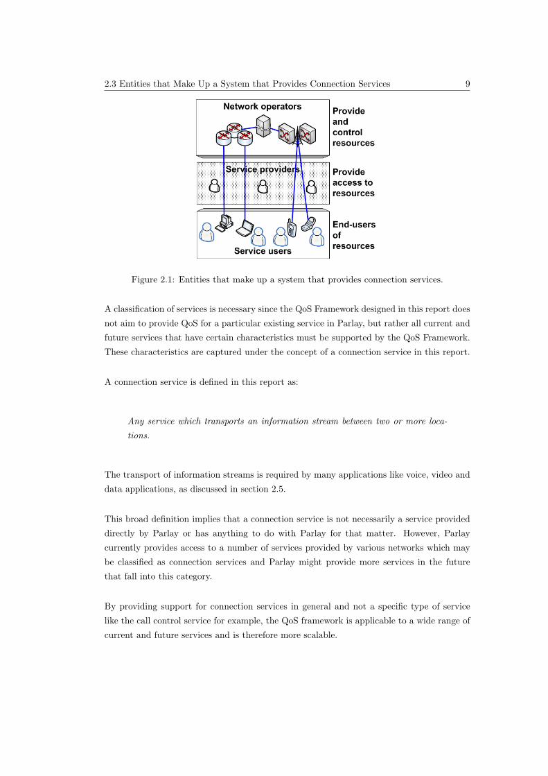
2.1 Entities that make up a system that provides connection services. . . . . . . . 9
2.2 An overview of all QoS components that must be present in a system in order
for the system to provide QoS for connection services. . . . . . . . . . . . . . 12
2.3 QoS dimension values. . . . . . . . . . . . . . . . . . . . . . . . . . . . . . . . 13
2.4 QoS mechanisms . . . . . . . . . . . . . . . . . . . . . . . . . . . . . . . . . . 14
3.1 Connection services that will be provided by Parlay. . . . . . . . . . . . . . . 17
3.2 Mapping components in the Parlay system to entities defined in section 2.3. . 18
4.1 High-level system overview illustrating the focus of the design. . . . . . . . . 24
4.2 Mapping of QoS components and design principles to Parlay entities. . . . . . 25
4.3 Design overview. . . . . . . . . . . . . . . . . . . . . . . . . . . . . . . . . . . 26
4.4 Division of QoS components into design sections. . . . . . . . . . . . . . . . . 27
4.5 The relationship between the three design components and the UML specifi-
cation. . . . . . . . . . . . . . . . . . . . . . . . . . . . . . . . . . . . . . . . . 27
LIST OF FIGURES xii
4.6 Summary of design influences. . . . . . . . . . . . . . . . . . . . . . . . . . . . 29
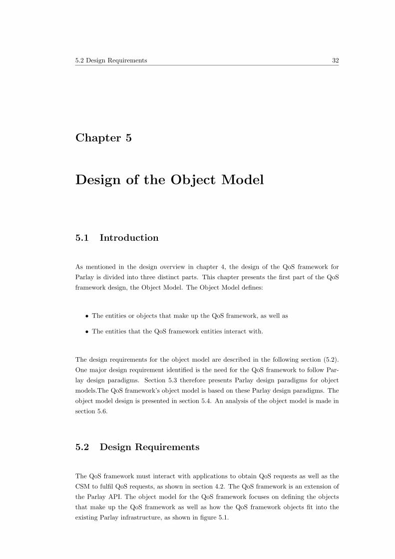
5.1 Required QoS framework object model. . . . . . . . . . . . . . . . . . . . . . 33
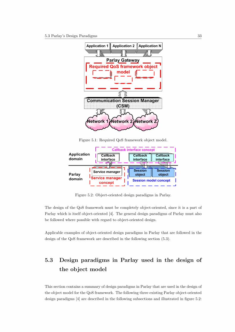
5.2 Object-oriented design paradigms in Parlay. . . . . . . . . . . . . . . . . . . . 33
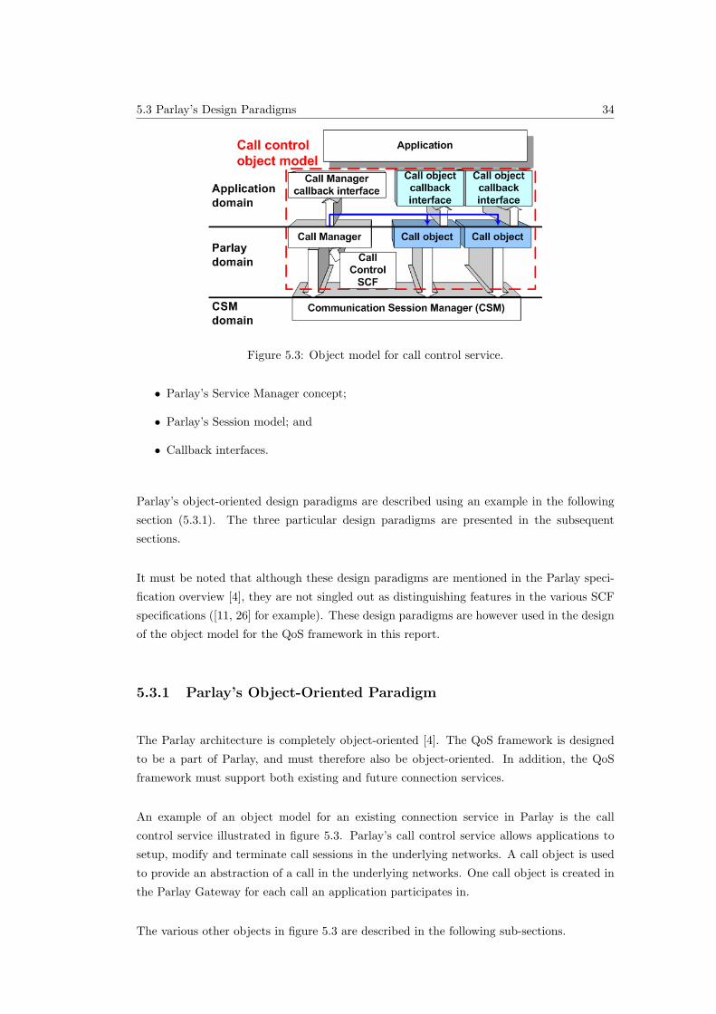
5.3 Object model for call control service. . . . . . . . . . . . . . . . . . . . . . . . 34
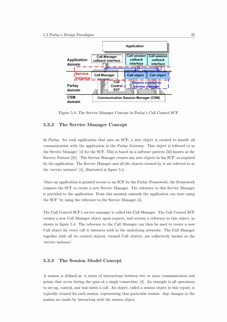
5.4 The Service Manager Concept in Parlay’s Call Control SCF. . . . . . . . . . . 35
5.5 Session model. . . . . . . . . . . . . . . . . . . . . . . . . . . . . . . . . . . . 36
5.6 Callback interfaces in Parlay. . . . . . . . . . . . . . . . . . . . . . . . . . . . 37
5.7 QoS framework’s object model. . . . . . . . . . . . . . . . . . . . . . . . . . . 37
5.8 QoS frameworks service manager. . . . . . . . . . . . . . . . . . . . . . . . . . 38
5.9 QoS frameworks Session model. . . . . . . . . . . . . . . . . . . . . . . . . . . 39
5.10 QoS frameworks Callback interfaces. . . . . . . . . . . . . . . . . . . . . . . . 40
5.11 Example illustrating the use of the QoS framework. . . . . . . . . . . . . . . . 40
6.1 Simple mapping example. . . . . . . . . . . . . . . . . . . . . . . . . . . . . . 47
6.2 A two-step mapping process. . . . . . . . . . . . . . . . . . . . . . . . . . . . 47
6.3 Decomposing services into Service Quality Features (SQFs). . . . . . . . . . . 49
7.1 The four user interaction mechanisms that are addressed in the information
model. . . . . . . . . . . . . . . . . . . . . . . . . . . . . . . . . . . . . . . . . 54
7.2 MSC showing how an application requests a QoS service from the QoS frame-
work. . . . . . . . . . . . . . . . . . . . . . . . . . . . . . . . . . . . . . . . . . 55
7.3 MSC showing how an application requests an SQF menu from a QoS session
object. . . . . . . . . . . . . . . . . . . . . . . . . . . . . . . . . . . . . . . . . 56
7.4 Interactions occurring during the QoS cycle. . . . . . . . . . . . . . . . . . . . 57
LIST OF FIGURES xiii
7.5 MSC showing how an application requests and receives reports from a QoS
session object. . . . . . . . . . . . . . . . . . . . . . . . . . . . . . . . . . . . . 60
8.1 Illustration of the relationship between the three models that make up the
design and the UML specification. . . . . . . . . . . . . . . . . . . . . . . . . 63
8.2 High-level relationships between classes in the QoS framework. . . . . . . . . 66
8.3 The extensions to the IpConnectivityManager interface. . . . . . . . . . . . . 67
8.4 The IpQoSSession interface. . . . . . . . . . . . . . . . . . . . . . . . . . . . . 68
8.5 The existing IpAppConnectivityManager interface has no additional methods
added. . . . . . . . . . . . . . . . . . . . . . . . . . . . . . . . . . . . . . . . . 71
8.6 The IpAppQoSSession interface. . . . . . . . . . . . . . . . . . . . . . . . . . 71
9.1 An overview of the QoS framework simulation design. . . . . . . . . . . . . . 80
9.2 CSM interface used for the simulation. . . . . . . . . . . . . . . . . . . . . . . 81
9.3 CSM callback interface used for the simulation. . . . . . . . . . . . . . . . . . 81
LIST OF TABLES xiv
List of Tables
2.1 High-level application QoS requirements adapted from [1]. . . . . . . . . . . . 11
3.1 Summary of QoS classes defined in [2]. . . . . . . . . . . . . . . . . . . . . . . 20
6.1 Generic QoS parameters, defined in [3]. . . . . . . . . . . . . . . . . . . . . . 48
6.2 The four Service Quality Features (SQFs) of the QoS framework. . . . . . . . 49
8.1 Naming scheme used in Parlay documentation [4]. . . . . . . . . . . . . . . . 65
8.2 The definition of the TpSQF data type. . . . . . . . . . . . . . . . . . . . . . 77
8.3 The definition of the TpSQFs data type. . . . . . . . . . . . . . . . . . . . . . 77
1.1 Background 1
Chapter 1
Introduction
1.1 Background
1.1.1 Connection Services
Many applications require the transport of information between two locations. A video
conversation application, for example, allows two users with the required terminals to have
a conversation in which they can both see and hear each other on their terminals’ screen
and speaker, respectively.
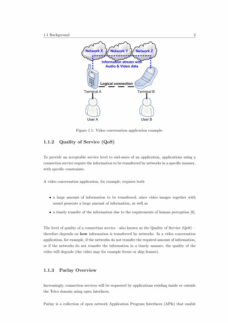
A video conversation example is illustrated in figure 1.1. In this example, users A and
B are having a video conversation, using terminals A and B, respectively. Terminal A
is connected to network X, while terminal B is connected to network Z. Network X and
network Z are not directly connected to each other, but are connected via a third network
– network Y. The networks together provide a logical connection between terminals A and
B – it appears to applications residing on the terminals that information is passed directly
between the terminals. The information transferred between the terminals via the networks
is the audio and video data representing the video images and audio sounds of the video
conversation. This information flow between terminals, and through the networks, is termed
an information stream (or stream flow [5]). An information stream may be uni- or bi-
directional.
The information transport service provided by the networks in this example is termed a
‘connection service’ in this report, and is further discussed in chapter 2.
1.1 Background 2
Figure 1.1: Video conversation application example.
1.1.2 Quality of Service (QoS)
To provide an acceptable service level to end-users of an application, applications using a
connection service require the information to be transferred by networks in a specific manner,
with specific constraints.
A video conversation application, for example, requires both
• a large amount of information to be transferred, since video images together with
sound generate a large amount of information, as well as
• a timely transfer of the information due to the requirements of human perception [6].
The level of quality of a connection service—also known as the Quality of Service (QoS)—
therefore depends on how information is transferred by networks. In a video conversation
application, for example, if the networks do not transfer the required amount of information,
or if the networks do not transfer the information in a timely manner, the quality of the
video will degrade (the video may for example freeze or skip frames).
1.1.3 Parlay Overview
Increasingly, connection services will be requested by applications residing inside or outside
the Telco domain using open interfaces.
Parlay is a collection of open network Application Program Interfaces (APIs) that enable
1.1 Background 3
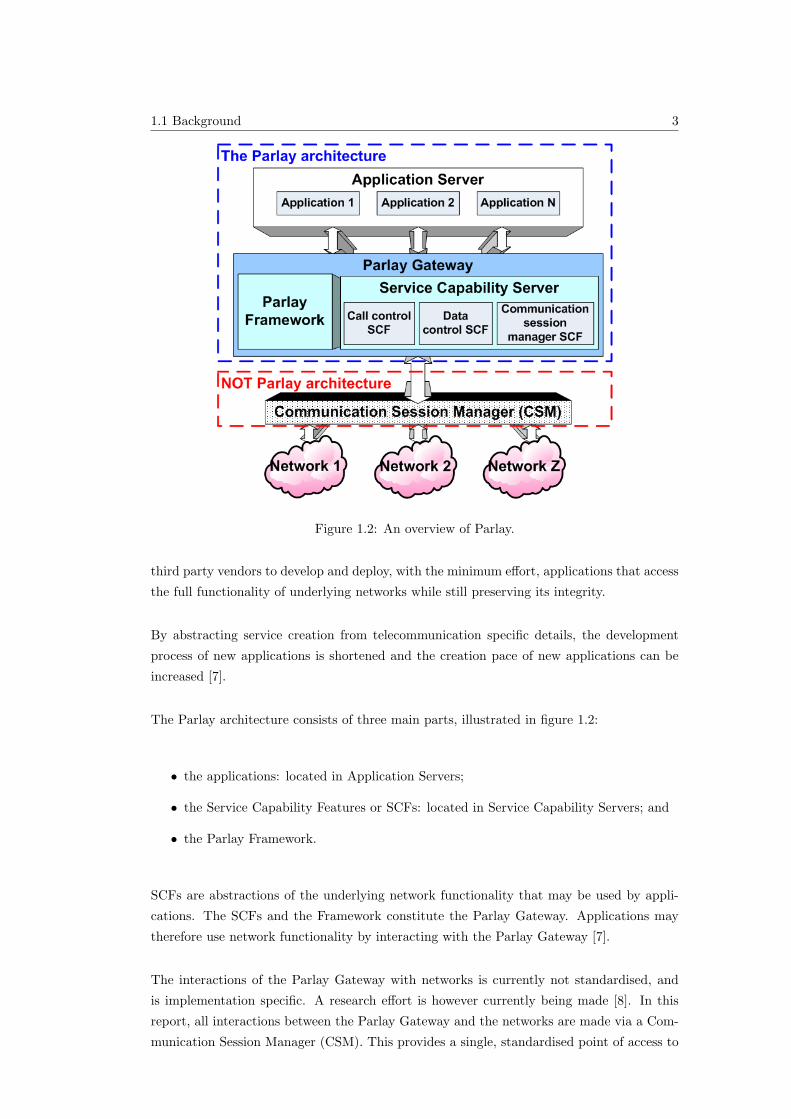
Figure 1.2: An overview of Parlay.
third party vendors to develop and deploy, with the minimum effort, applications that access
the full functionality of underlying networks while still preserving its integrity.
By abstracting service creation from telecommunication specific details, the development
process of new applications is shortened and the creation pace of new applications can be
increased [7].
The Parlay architecture consists of three main parts, illustrated in figure 1.2:
• the applications: located in Application Servers;
• the Service Capability Features or SCFs: located in Service Capability Servers; and
• the Parlay Framework.
SCFs are abstractions of the underlying network functionality that may be used by appli-
cations. The SCFs and the Framework constitute the Parlay Gateway. Applications may
therefore use network functionality by interacting with the Parlay Gateway [7].
The interactions of the Parlay Gateway with networks is currently not standardised, and
is implementation specific. A research effort is however currently being made [8]. In this
report, all interactions between the Parlay Gateway and the networks are made via a Com-
munication Session Manager (CSM). This provides a single, standardised point of access to
1.2 Problem Specification 4
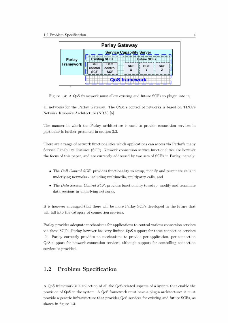
Figure 1.3: A QoS framework must allow existing and future SCFs to plugin into it.
all networks for the Parlay Gateway. The CSM’s control of networks is based on TINA’s
Network Resource Architecture (NRA) [5].
The manner in which the Parlay architecture is used to provide connection services in
particular is further presented in section 3.2.
There are a range of network functionalities which applications can access via Parlay’s many
Service Capability Features (SCF). Network connection service functionalities are however
the focus of this paper, and are currently addressed by two sets of SCFs in Parlay, namely:
• The Call Control SCF : provides functionality to setup, modify and terminate calls in
underlying networks - including multimedia, multiparty calls, and
• The Data Session Control SCF : provides functionality to setup, modify and terminate
data sessions in underlying networks.
It is however envisaged that there will be more Parlay SCFs developed in the future that
will fall into the category of connection services.
Parlay provides adequate mechanisms for applications to control various connection services
via these SCFs. Parlay however has very limited QoS support for these connection services
[9]. Parlay currently provides no mechanisms to provide per-application, per-connection
QoS support for network connection services, although support for controlling connection
services is provided.
1.2 Problem Specification
A QoS framework is a collection of all the QoS-related aspects of a system that enable the
provision of QoS in the system. A QoS framework must have a plugin architecture: it must
provide a generic infrastructure that provides QoS services for existing and future SCFs, as
shown in figure 1.3.
1.3 Scope of this Report 5
This report presents a QoS framework for connection services provided by Parlay. The
QoS framework thus enables the provision and control of QoS by Parlay to applications for
connection services like Parlay’s call and data session control services.
The QoS framework must:
• Provide per-application, per-connection QoS support for connection services provided
by Parlay;
• Support existing and future connection services in Parlay;
• Follow Parlay’s existing design paradigms; and
• Co-exist with and make use of existing and future Parlay infrastructure where possible.
1.3 Scope of this Report
This report presents:
• The design of a QoS framework for connection services in Parlay;
• A formal UML [10] specification of the design, similar to that provided in the Parlay
specifications (see [11] for an example of such a specification); and
• Details of a proof of concept simulation that has been developed to validate the design
presented in this report.
The required interactions of Parlay with networks is abstracted in the design using the
concept of the Communication Session Manager (CSM), as described in section 1.1.3. The
requirements of the QoS framework between Parlay and networks are therefore also identified
only at a high level in this report. A detailed design of these interactions are not presented
however.
The following items regarding the QoS framework presented in this report must be addressed
in future work:
• The mapping of Service Quality Features (SQFs – defined in section 6.3.2) to generic
QoS parameters must be further investigated;
• The validity of the generic QoS parameters defined in Parlay and used in the QoS
framework must also be investigated;
• The addition of exceptions to the UML specification must be made;
1.4 Document Overview 6
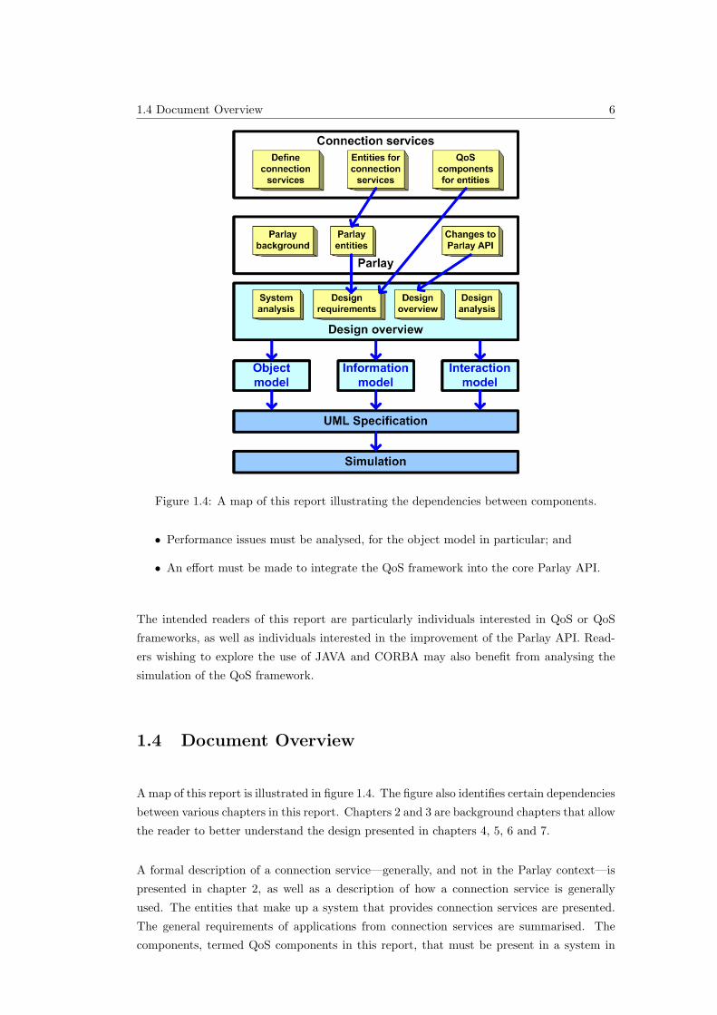
Figure 1.4: A map of this report illustrating the dependencies between components.
• Performance issues must be analysed, for the object model in particular; and
• An effort must be made to integrate the QoS framework into the core Parlay API.
The intended readers of this report are particularly individuals interested in QoS or QoS
frameworks, as well as individuals interested in the improvement of the Parlay API. Read-
ers wishing to explore the use of JAVA and CORBA may also benefit from analysing the
simulation of the QoS framework.
1.4 Document Overview
A map of this report is illustrated in figure 1.4. The figure also identifies certain dependencies
between various chapters in this report. Chapters 2 and 3 are background chapters that allow
the reader to better understand the design presented in chapters 4, 5, 6 and 7.
A formal description of a connection service—generally, and not in the Parlay context—is
presented in chapter 2, as well as a description of how a connection service is generally
used. The entities that make up a system that provides connection services are presented.
The general requirements of applications from connection services are summarised. The
components, termed QoS components in this report, that must be present in a system in
1.4 Document Overview 7
order for the system to be able to provide QoS for connection services are described. The
entity in the system that must implement each QoS component is also identified. This QoS
component concept is used in the design (in chapter 4) to identify what components the
QoS framework must implement, and what components must be implemented by external
entities (and are therefore out of the scope of the QoS framework).
An analysis of Parlay is made in chapter 3. A brief overview of Parlay is given, describing
the Parlay architecture, how Parlay works, and the many services provided by Parlay. Con-
nection services in Parlay are described further, including an analysis of the role Parlay plays
in the complete system in terms of the entities presented in chapter 2. Existing QoS aspects
in Parlay are presented, since these must be considered in the design of the QoS framework.
The changes permitted to the Parlay API are listed, since these are also considered in the
design the QoS framework to ensure backward compatibility of the Parlay API if the QoS
framework is added to it.
An overview of the design is presented in chapter 4. The design requirements are described,
followed by a summary of the three parts of the design presented in chapters 5, 6 and 7.
A formal, technology-independent specification of the complete design composing all three
parts of the design is presented using UML [10] in chapter 8.
Chapter 9 presents the proof of concept or simulation of the design. The details of the
simulation are given, and an analysis of the simulation is made. The simulation, unlike the
UML specification, is technology-specific: it is a multi-threaded [12], distributed CORBA
[13] application implemented in JAVA [14] (Java SDK version 1.5). The source code for the
simulation of the QoS framework may be found in [15], together with the detailed source
code documentation. An on-line, browsable version of the source code documentation may
be found in [16].
A summary of the work followed by an analysis of the QoS framework, and a summary of
the required future work for the QoS framework is presented in chapter 10.
The report is intended to be read in a sequential fashion. The three different parts of the
design may however be read in any order. However, readers only interested in the potential
effect of this report on the Parlay API may refer to the UML specification chapter alone.
Also, readers only interested in a reference implementation of a JAVA/CORBA distributed
application may refer to the simulation chapter alone.
2.2 What is a Connection Service? 8
Chapter 2
Connection Services
2.1 Introduction
The QoS framework presented in this report provides QoS support specifically for connection
services in Parlay. To understand the design of the QoS framework, a basic understanding
of connection services in general is therefore required. This chapter thus presents a formal
description of a connection service in general and not in the Parlay context as a basis for
the design presented in this report.
A formal definition of a connection service is presented in the following section (2.2). The
entities that make up a system that provides connection service are described in section
2.3. The manner in which a connection service is typically used by the various entities is
presented in section 2.4. Section 2.5 summarises the general requirements of applications
from a connection service.
The various components (termed QoS components in this report) that must be present in a
system (generally and not in the Parlay context) in order for the system to provide QoS are
presented in section 2.6. The entity defined in section 2.3 that must implement each QoS
component is also identified.
2.2 What is a Connection Service?
The term connection service does not refer to a particular concrete service in this report,
but rather it is used to classify a range of telecom services that have specific common
characteristics. This classification is used in this report to identify the type of services in
Parlay for which the QoS Framework designed in this report aims to provide QoS services.
2.3 Entities that Make Up a System that Provides Connection Services 9
Figure 2.1: Entities that make up a system that provides connection services.
A classification of services is necessary since the QoS Framework designed in this report does
not aim to provide QoS for a particular existing service in Parlay, but rather all current and
future services that have certain characteristics must be supported by the QoS Framework.
These characteristics are captured under the concept of a connection service in this report.
A connection service is defined in this report as:
Any service which transports an information stream between two or more loca-
tions.
The transport of information streams is required by many applications like voice, video and
data applications, as discussed in section 2.5.
This broad definition implies that a connection service is not necessarily a service provided
directly by Parlay or has anything to do with Parlay for that matter. However, Parlay
currently provides access to a number of services provided by various networks which may
be classified as connection services and Parlay might provide more services in the future
that fall into this category.
By providing support for connection services in general and not a specific type of service
like the call control service for example, the QoS framework is applicable to a wide range of
current and future services and is therefore more scalable.
2.5 Requirements from Connection Services 10
2.3 Entities that Make Up a System that Provides Con-
nection Services
There are 3 primary entities identified in a system providing a connection service shown in
figure 2.1:
• Network operators: provide and control the actual connection service resources like
switches, routers and physical links;
• Service providers: provide service users with access to and control of connection ser-
vices and other resources provided by network operators; and
• Service users: control or use connection services using their terminals.
2.4 Using Connection Services
A connection service is typically provided by a group of networks collectively to applications
running on service users’ terminals. A connection service transports information streams
between two or more service users’ terminals.
Terminals may be either:
• A simple terminal device like a telephone or multimedia device, or
• A computing system in which appropriate applications are deployed.
End-users use their terminals for two primary purposes in the context of a connection service:
• Service control: to setup, modify and terminate connection services provided by net-
works, or
• Service usage: to use the application that requires the connection service, like a video
conversation application, for example – see section 1.1.1.
2.5 Requirements from Connection Services
To provide an acceptable service level to end-users of an application, applications using a
connection service require the information to be transferred by networks in a specific manner,
with specific constraints.
2.6 QoS Components 11
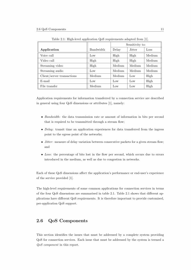
Table 2.1: High-level application QoS requirements adapted from [1].
Sensitivity to:
Application Bandwidth Delay Jitter Loss
Voice call Low High High Medium
Video call High High High Medium
Streaming video High Medium Medium Medium
Streaming audio Low Medium Medium Medium
Client/server transactions Medium Medium Low High
E-mail Low Low Low High
File transfer Medium Low Low High
Application requirements for information transferred by a connection service are described
in general using four QoS dimensions or attributes [1], namely:
• Bandwidth: the data transmission rate or amount of information in bits per second
that is required to be transmitted through a stream flow;
• Delay : transit time an application experiences for data transferred from the ingress
point to the egress point of the networks;
• Jitter : measure of delay variation between consecutive packets for a given stream flow;
and
• Loss: the percentage of bits lost in the flow per second, which occurs due to errors
introduced in the medium, as well as due to congestion in networks.
Each of these QoS dimensions affect the application’s performance or end-user’s experience
of the service provided [1].
The high-level requirements of some common applications for connection services in terms
of the four QoS dimensions are summarised in table 2.1. Table 2.1 shows that different ap-
plications have different QoS requirements. It is therefore important to provide customised,
per-application QoS support.
2.6 QoS Components
This section identifies the issues that must be addressed by a complete system providing
QoS for connection services. Each issue that must be addressed by the system is termed a
QoS component in this report.
2.6 QoS Components 12
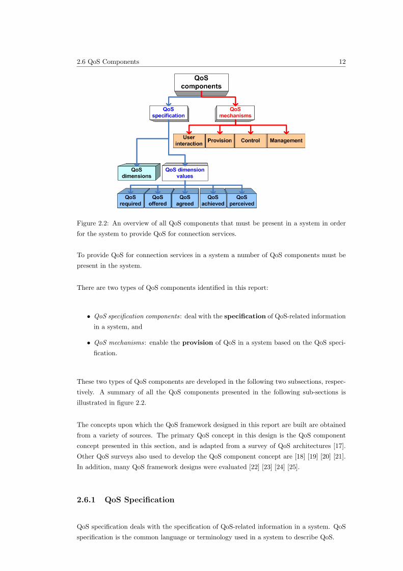
Figure 2.2: An overview of all QoS components that must be present in a system in order
for the system to provide QoS for connection services.
To provide QoS for connection services in a system a number of QoS components must be
present in the system.
There are two types of QoS components identified in this report:
• QoS specification components: deal with the specification of QoS-related information
in a system, and
• QoS mechanisms: enable the provision of QoS in a system based on the QoS speci-
fication.
These two types of QoS components are developed in the following two subsections, respec-
tively. A summary of all the QoS components presented in the following sub-sections is
illustrated in figure 2.2.
The concepts upon which the QoS framework designed in this report are built are obtained
from a variety of sources. The primary QoS concept in this design is the QoS component
concept presented in this section, and is adapted from a survey of QoS architectures [17].
Other QoS surveys also used to develop the QoS component concept are [18] [19] [20] [21].
In addition, many QoS framework designs were evaluated [22] [23] [24] [25].
2.6.1 QoS Specification
QoS specification deals with the specification of QoS-related information in a system. QoS
specification is the common language or terminology used in a system to describe QoS.
2.6 QoS Components 13
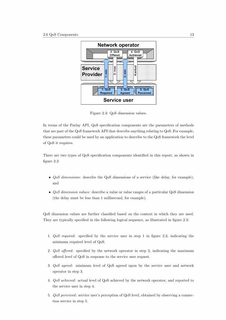
Figure 2.3: QoS dimension values.
In terms of the Parlay API, QoS specification components are the parameters of methods
that are part of the QoS framework API that describe anything relating to QoS. For example,
these parameters could be used by an application to describe to the QoS framework the level
of QoS it requires.
There are two types of QoS specification components identified in this report, as shown in
figure 2.2:
• QoS dimensions: describe the QoS dimensions of a service (like delay, for example),
and
• QoS dimension values: describe a value or value ranges of a particular QoS dimension
(the delay must be less than 1 millisecond, for example).
QoS dimension values are further classified based on the context in which they are used.
They are typically specified in the following logical sequence, as illustrated in figure 2.3:
1. QoS required : specified by the service user in step 1 in figure 2.3, indicating the
minimum required level of QoS.
2. QoS offered : specified by the network operator in step 2, indicating the maximum
offered level of QoS in response to the service user request.
3. QoS agreed : minimum level of QoS agreed upon by the service user and network
operator in step 3.
4. QoS achieved : actual level of QoS achieved by the network operator, and reported to
the service user in step 4.
5. QoS perceived : service user’s perception of QoS level, obtained by observing a connec-
tion service in step 5.
2.6 QoS Components 14
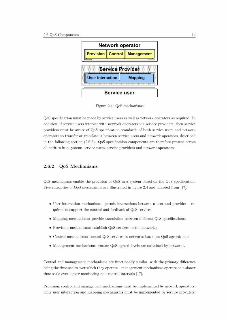
Figure 2.4: QoS mechanisms
QoS specification must be made by service users as well as network operators as required. In
addition, if service users interact with network operators via service providers, then service
providers must be aware of QoS specification standards of both service users and network
operators to transfer or translate it between service users and network operators, described
in the following section (2.6.2). QoS specification components are therefore present across
all entities in a system: service users, service providers and network operators.
2.6.2 QoS Mechanisms
QoS mechanisms enable the provision of QoS in a system based on the QoS specification.
Five categories of QoS mechanisms are illustrated in figure 2.4 and adapted from [17]:
• User interaction mechanisms: permit interactions between a user and provider – re-
quired to support the control and feedback of QoS services;
• Mapping mechanisms: provide translation between different QoS specifications;
• Provision mechanisms: establish QoS services in the networks;
• Control mechanisms: control QoS services in networks based on QoS agreed; and
• Management mechanisms: ensure QoS agreed levels are sustained by networks.
Control and management mechanisms are functionally similar, with the primary difference
being the time-scales over which they operate – management mechanisms operate on a slower
time scale over longer monitoring and control intervals [17].
Provision, control and management mechanisms must be implemented by network operators.
Only user interaction and mapping mechanisms must be implemented by service providers.
2.7 Conclusion 15
2.7 Conclusion
The ‘connection service’ concept is used in this report to classify the range of Parlay services
which are supported by the QoS Framework designed in this report. A formal description of a
connection service is presented in this chapter, together with a summary of how a connection
service is typically used. The Quality of Service (QoS) requirements from connection services
are outlined in this chapter.
In chapter 4 entities in the Parlay system are mapped to the entities identified in section
2.3. The components that must be present in a complete system in order for the system
to provide QoS for connection services are identified in this chapter. These two factors are
used in chapter 4 to identify what components must be implemented by the QoS framework,
which is just one part of a complete system, in order for the complete system to provide
QoS for connection services.
3.2 Connection Services in Parlay 16
Chapter 3
An Analysis of Parlay
3.1 Introduction
The QoS framework presented in this report is designed to provide QoS support for con-
nection services when a Parlay Gateway is used to allow applications to access network
capabilities. An understanding of Parlay is therefore required to understand the design of
the QoS framework. This chapter provides the reader with the information related to Parlay
necessary to understand the design of the QoS framework presented in this report.
A brief overview of Parlay is given in the introductory chapter (section 1.1.3), describing
how Parlay works and the services provided by Parlay, as well as a description of the Parlay
architecture. Connection services in Parlay are described in the following section 3.2. An
analysis of the role Parlay plays in the context of the complete system in terms of the entities
presented in section 2.3 is presented in section 3.3. Existing QoS aspects in Parlay are
identified in section 3.4, since these must be considered in the design of the QoS framework
presented in chapter 4. The permitted and forbidden changes to the Parlay API specification
are summarised in section 3.5.
3.2 Connection Services in Parlay
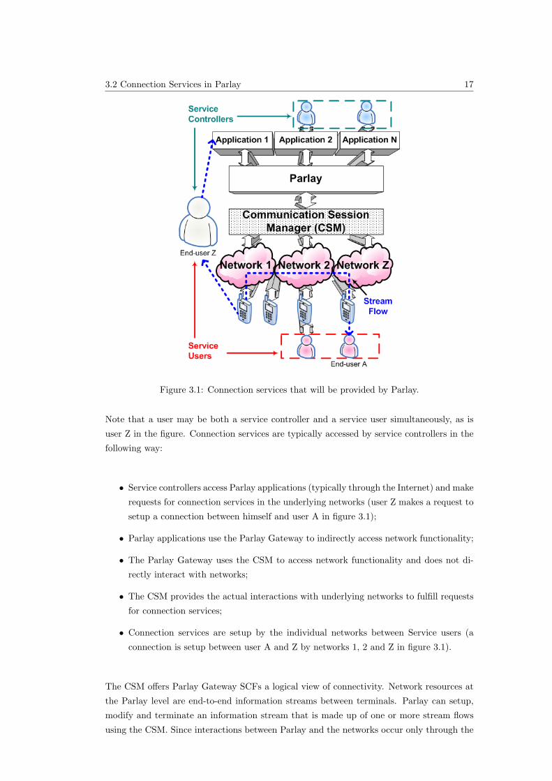
An overview of the use of connection services in Parlay is illustrated in figure 3.1. Two types
of users are identified in Parlay :
• Service controllers: users that setup and control network services (via applications) or
third party applications, and
• Service users: the actual users of network connection services.
3.2 Connection Services in Parlay 17
Figure 3.1: Connection services that will be provided by Parlay.
Note that a user may be both a service controller and a service user simultaneously, as is
user Z in the figure. Connection services are typically accessed by service controllers in the
following way:
• Service controllers access Parlay applications (typically through the Internet) and make
requests for connection services in the underlying networks (user Z makes a request to
setup a connection between himself and user A in figure 3.1);
• Parlay applications use the Parlay Gateway to indirectly access network functionality;
• The Parlay Gateway uses the CSM to access network functionality and does not di-
rectly interact with networks;
• The CSM provides the actual interactions with underlying networks to fulfill requests
for connection services;
• Connection services are setup by the individual networks between Service users (a
connection is setup between user A and Z by networks 1, 2 and Z in figure 3.1).
The CSM offers Parlay Gateway SCFs a logical view of connectivity. Network resources at
the Parlay level are end-to-end information streams between terminals. Parlay can setup,
modify and terminate an information stream that is made up of one or more stream flows
using the CSM. Since interactions between Parlay and the networks occur only through the
3.3 Entities in Parlay 18
Figure 3.2: Mapping components in the Parlay system to entities defined in section 2.3.
CSM, the CSM must also provide per-connection QoS support to Parlay, abstracting the
complexities of the networks. The implementation of the CSM is however not in the scope
of the work presented in this report.
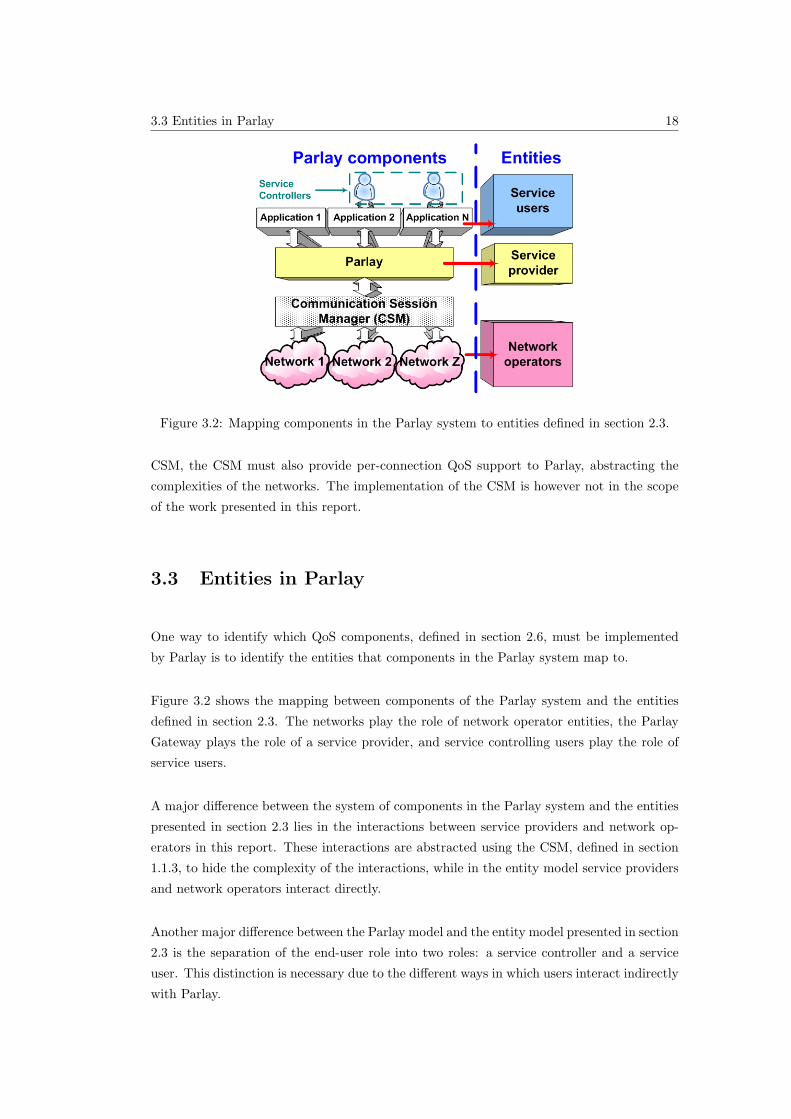
3.3 Entities in Parlay
One way to identify which QoS components, defined in section 2.6, must be implemented
by Parlay is to identify the entities that components in the Parlay system map to.
Figure 3.2 shows the mapping between components of the Parlay system and the entities
defined in section 2.3. The networks play the role of network operator entities, the Parlay
Gateway plays the role of a service provider, and service controlling users play the role of
service users.
A major difference between the system of components in the Parlay system and the entities
presented in section 2.3 lies in the interactions between service providers and network op-
erators in this report. These interactions are abstracted using the CSM, defined in section
1.1.3, to hide the complexity of the interactions, while in the entity model service providers
and network operators interact directly.
Another major difference between the Parlay model and the entity model presented in section
2.3 is the separation of the end-user role into two roles: a service controller and a service
user. This distinction is necessary due to the different ways in which users interact indirectly
with Parlay.
3.4 Existing QoS Aspects in Parlay 19
3.4 Existing QoS Aspects in Parlay
There is at the time of writing limited support for QoS in Parlay. In particular, the following
three QoS features have been identified in the Parlay standards:
• Enterprise QoS support;
• Generic QoS parameters definitions; and
• A data type for Quality of Service classes is defined.
The generic QoS parameters are described in section 6.3.2. The other two existing QoS
features in Parlay are summarised in the following two subsections.
3.4.1 Enterprise QoS Support (for Virtual Private Networks)
As was mentioned before, a limitation in the Parlay API is that there are no methods for
QoS control and management that can be used by external applications. QoS management
has been partly addressed by the Parlay APIs through the introduction of the Connectivity
Manager SCF [4]. This SCF allows an enterprise to enquire about and control aspects of QoS
in a virtual private network provided by the network provider. However, the connectivity
manager SCF was designed with the intention of providing QoS management on an enterprise
scale and not for individual users. The intended user of the connectivity manager SCF is the
enterprise operator administration tool [9]. Therefore, Parlay does not provide any APIs for
a server-centric service application to perform QoS management on behalf of its individual
users [9].
The Connectivity Manager SCF, however, provides an adequate infrastructure for the QoS
framework presented in this report. The Connectivity Manager SCF infrastructure is there-
fore used to build the QoS framework’s object model, as discussed in chapter 5.
3.4.2 Definition of QoS Traffic Classes
The ‘TpDataSessionQosClass’ is a data type specified in Parlay [26]. This data type is
intended for use in a data session or a multi-media call session. The data type defines four
QoS classes, namely:
1. Conversational QoS class,
2. Streaming QoS class,
3.4 Existing QoS Aspects in Parlay 20
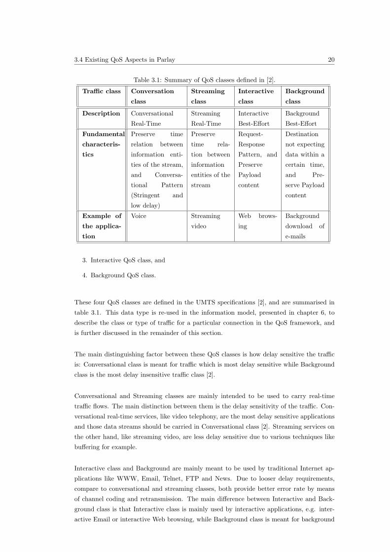
Table 3.1: Summary of QoS classes defined in [2].
Traffic class Conversation
class
Streaming
class
Interactive
class
Background
class
Description Conversational
Real-Time
Streaming
Real-Time
Interactive
Best-Effort
Background
Best-Effort
Fundamental
characteris-
tics
Preserve time
relation between
information enti-
ties of the stream,
and Conversa-
tional Pattern
(Stringent and
low delay)
Preserve
time rela-
tion between
information
entities of the
stream
Request-
Response
Pattern, and
Preserve
Payload
content
Destination
not expecting
data within a
certain time,
and Pre-
serve Payload
content
Example of
the applica-
tion
Voice Streaming
video
Web brows-
ing
Background
download of
e-mails
3. Interactive QoS class, and
4. Background QoS class.
These four QoS classes are defined in the UMTS specifications [2], and are summarised in
table 3.1. This data type is re-used in the information model, presented in chapter 6, to
describe the class or type of traffic for a particular connection in the QoS framework, and
is further discussed in the remainder of this section.
The main distinguishing factor between these QoS classes is how delay sensitive the traffic
is: Conversational class is meant for traffic which is most delay sensitive while Background
class is the most delay insensitive traffic class [2].
Conversational and Streaming classes are mainly intended to be used to carry real-time
traffic flows. The main distinction between them is the delay sensitivity of the traffic. Con-
versational real-time services, like video telephony, are the most delay sensitive applications
and those data streams should be carried in Conversational class [2]. Streaming services on
the other hand, like streaming video, are less delay sensitive due to various techniques like
buffering for example.
Interactive class and Background are mainly meant to be used by traditional Internet ap-
plications like WWW, Email, Telnet, FTP and News. Due to looser delay requirements,
compare to conversational and streaming classes, both provide better error rate by means
of channel coding and retransmission. The main difference between Interactive and Back-
ground class is that Interactive class is mainly used by interactive applications, e.g. inter-
active Email or interactive Web browsing, while Background class is meant for background
3.5 Changes Permitted to the Parlay API 21
traffic, e.g. background download of Emails or background file downloading. Responsiveness
of the interactive applications is ensured by separating interactive and background appli-
cations. Traffic in the Interactive class has higher priority in scheduling than Background
class traffic, so background applications use transmission resources only when interactive
applications do not need them. This is very important in wireless environment where the
bandwidth is low compared to fixed networks [2].
3.5 Changes Permitted to the Parlay API
The design presented in this report aims to extend the Parlay API specifications to provide
QoS support for connection services in Parlay. To enable backward compatibility in the
Parlay API specifications, only certain types of changes may be made to the Parlay APIs.
Anything beyond these changes is not permitted, as described in [4]. A summary of the
changes that are permitted to the Parlay APIs are presented in the following subsections.
These ‘rules’ are carefully considered in the design of the QoS framework presented in this
report.
3.5.1 Changes Permitted to the Parlay Gateway Side
Only the following changes are permitted on the Parlay Gateway side [4]:
• Addition of a new interface.
• Addition of a new method to an existing or new interface.
• Addition and removal of exceptions if the implementation uses the Application ver-
sioning convention specified in [4].
3.5.2 Changes Permitted to the Application Side
Only the following changes are permitted on the Application side [4]:
• Addition of a new interface.
• Addition of a new method.
• Addition and removal of exceptions if the implementation uses the Application ver-
sioning convention specified in [4].
3.6 Conclusion 22
3.5.3 Changes Permitted to Data Types
Only the following changes are permitted to existing Data types [4]:
• Elements may be added to ‘sequence’ data types. Care should be taken when adding
elements to data types that are sent back to the client: The client may be outdated
and thus not be able to interpret the new element. Only information that has not
been available before, and therefore is not expected by the client, may be transferred
in added elements. Information that has been available before, and therefore possibly
expected by the client, may not be modified in any way.
• Elements may be added to ‘tagged choice of data elements’ data types, which evaluate
to one of a choice of data elements, if they are always sent from client to server:
either within a parameter of a server side method, or within the result of a client side
method. For example, the TpCallError data type currently has 5 possible error types
[26]. More error types may be added to this data type because it is a ‘tagged choice
of data elements’ data type.
3.6 Conclusion
This chapter provides the reader with the information related to Parlay necessary to un-
derstand the design of the QoS framework presented in this report. A review of the Parlay
architecture is presented, as well as various other aspects of Parlay relating to connection
services. In particular, the usage of connection services in Parlay is described, together with
an identification of entities in the Parlay model.
The entities that components in the Parlay system map to are used in section 4.3 to identify
which QoS components must be implemented by each Parlay component. The existing QoS
aspects in Parlay identified in section 3.4 are used in the design of the QoS framework,
presented in chapters 4 to 7, where applicable. The permitted changes to the Parlay API
specification identified in section 3.5 are also considered in the various parts of the design
to ensure backward compatibility of the Parlay API to previous versions of the Parlay API
in the event that the QoS framework is added to the API.
4.2 System Analysis 23
Chapter 4
Design Requirements and Approach
4.1 Introduction
An overview of the design requirements and approach to the design of the QoS framework
for Parlay is presented in this chapter. The design of the QoS framework is divided into
three components or models, as discussed in section 4.4:
1. The object model, presented in chapter 5
2. The information model, presented in chapter 6
3. The interaction model, presented in chapter 7
This chapter introduces the high-level design of these three components of the design pre-
sented in the following three chapters, as well as how these components fit together.
An analysis of the complete system in which the QoS framework must be designed is pre-
sented in section 4.2. The requirements of the design are summarised in section 4.3, followed
by an overview of the QoS framework design in section 4.4. A summary of the various con-
cepts which influenced the different parts of the design is given in section 4.6.
A formal specification of the complete design is presented using UML [10] in chapter 8.
4.2 System Analysis
An analysis of the complete system in which the QoS framework must be designed is pre-
sented in this section. This analysis illustrates on a high-level the entities that the QoS
4.2 System Analysis 24
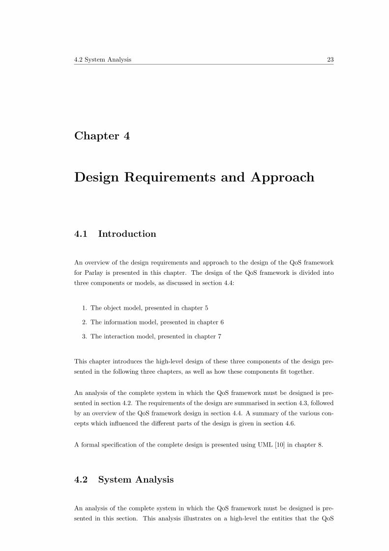
Figure 4.1: High-level system overview illustrating the focus of the design.
framework must interact with to provide QoS services to requesting applications. A high-
level system overview is illustrated in figure 4.1.
The QoS framework is a component of the Parlay API, and must therefore interact with
certain entities within the Parlay API to support existing and future SCFs, a topic examined
in chapter 5.
The QoS framework must interact directly with two external entities:
• Applications: to obtain QoS requests for Parlay services, and
• The CSM: to fulfil QoS requests received from applications.
The CSM, introduced in section 1.1.3, must interact with the various networks involved in
the requested QoS services. The networks interact with the connected user terminals and
other equipment to fulfill the QoS requests from applications.
The focus in this report is on the interactions between:
• Applications and the QoS framework, and
4.3 Design Requirements 25
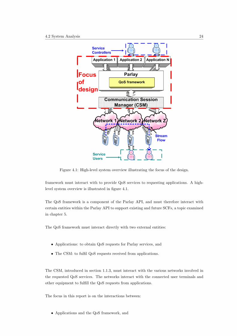
Figure 4.2: Mapping of QoS components and design principles to Parlay entities.
• The QoS framework and the Communication Session Manager (CSM)
The other interactions, between the CSM and networks, and between networks and termi-
nals, are outside the scope of this report. Details about certain interactions between the
CSM and various networks may be found in [8].
4.3 Design Requirements
A QoS framework is a collection of all the QoS-related aspects of a system that enable the
provision of QoS in the system. The QoS components of a system that must be present in
a system’s QoS framework in order for the system to provide QoS for connection services
are presented in section 2.6. The QoS-related aspects, both QoS components and further
design principles, are mapped to entities in the Parlay system in figure 4.2, illustrating the
scope of QoS components and design principles in various Parlay entities. As shown in the
figure, QoS specification components are present across all entities since all entities specify
QoS. User interaction components are present across all entities except network operators in
Parlay because user interaction is primarily performed by applications and not networks
in Parlay. The network operator entity must however perform the actual network control
mechanisms of provision, control and management. The mapping component is only in the
scope of the Parlay Gateway which must map QoS specification between applications and
the CSM.
4.4 Design Overview 26
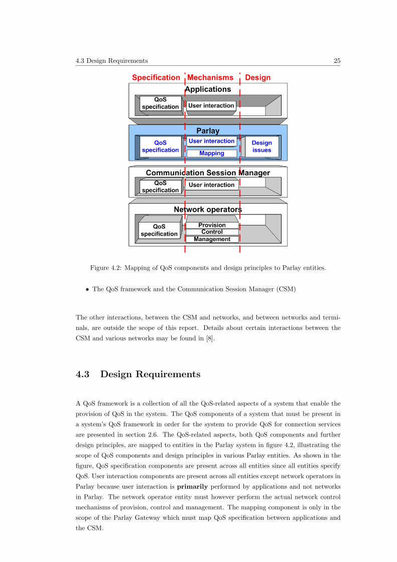
Figure 4.3: Design overview.
QoS specification, mapping and user interaction mechanisms are therefore the only compo-
nents that must be provided by the QoS framework for Parlay. All other components are
outside the scope of the QoS framework. In addition, various design issues must also be
considered in the design of the framework, as identified in section 5.3.
4.4 Design Overview
To reduce the complexity of the design, the divide-and-conquer approach is used. The design
is divided into 3 smaller, more manageable parts.
An overview of the design of the QoS framework is illustrated in figure 4.3. The three
components of the design are:
1. The Object Model: presented in chapter 5, identifies the entities or objects that com-
pose and interact with the QoS framework at the various levels.
4.5 Analysis of QoS Framework Design 27
Figure 4.4: Division of QoS components into design sections.
Figure 4.5: The relationship between the three design components and the UML specifica-
tion.
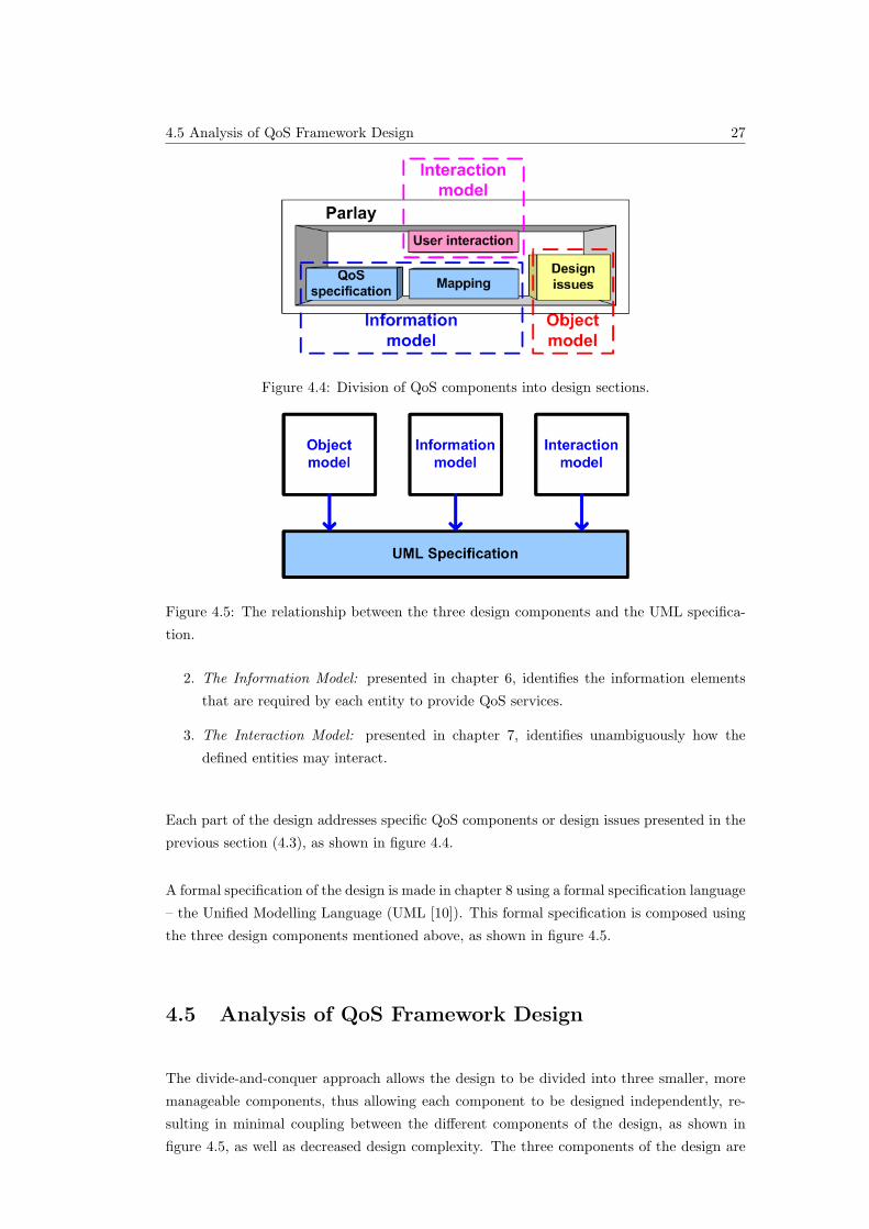
2. The Information Model: presented in chapter 6, identifies the information elements
that are required by each entity to provide QoS services.
3. The Interaction Model: presented in chapter 7, identifies unambiguously how the
defined entities may interact.
Each part of the design addresses specific QoS components or design issues presented in the
previous section (4.3), as shown in figure 4.4.
A formal specification of the design is made in chapter 8 using a formal specification language
– the Unified Modelling Language (UML [10]). This formal specification is composed using
the three design components mentioned above, as shown in figure 4.5.
4.5 Analysis of QoS Framework Design
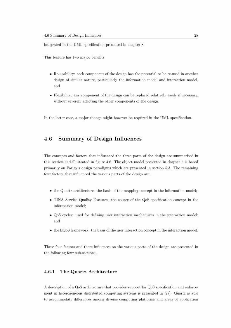
The divide-and-conquer approach allows the design to be divided into three smaller, more
manageable components, thus allowing each component to be designed independently, re-
sulting in minimal coupling between the different components of the design, as shown in
figure 4.5, as well as decreased design complexity. The three components of the design are
4.6 Summary of Design Influences 28
integrated in the UML specification presented in chapter 8.
This feature has two major benefits:
• Re-usability: each component of the design has the potential to be re-used in another
design of similar nature, particularly the information model and interaction model,
and
• Flexibility: any component of the design can be replaced relatively easily if necessary,
without severely affecting the other components of the design.
In the latter case, a major change might however be required in the UML specification.
4.6 Summary of Design Influences
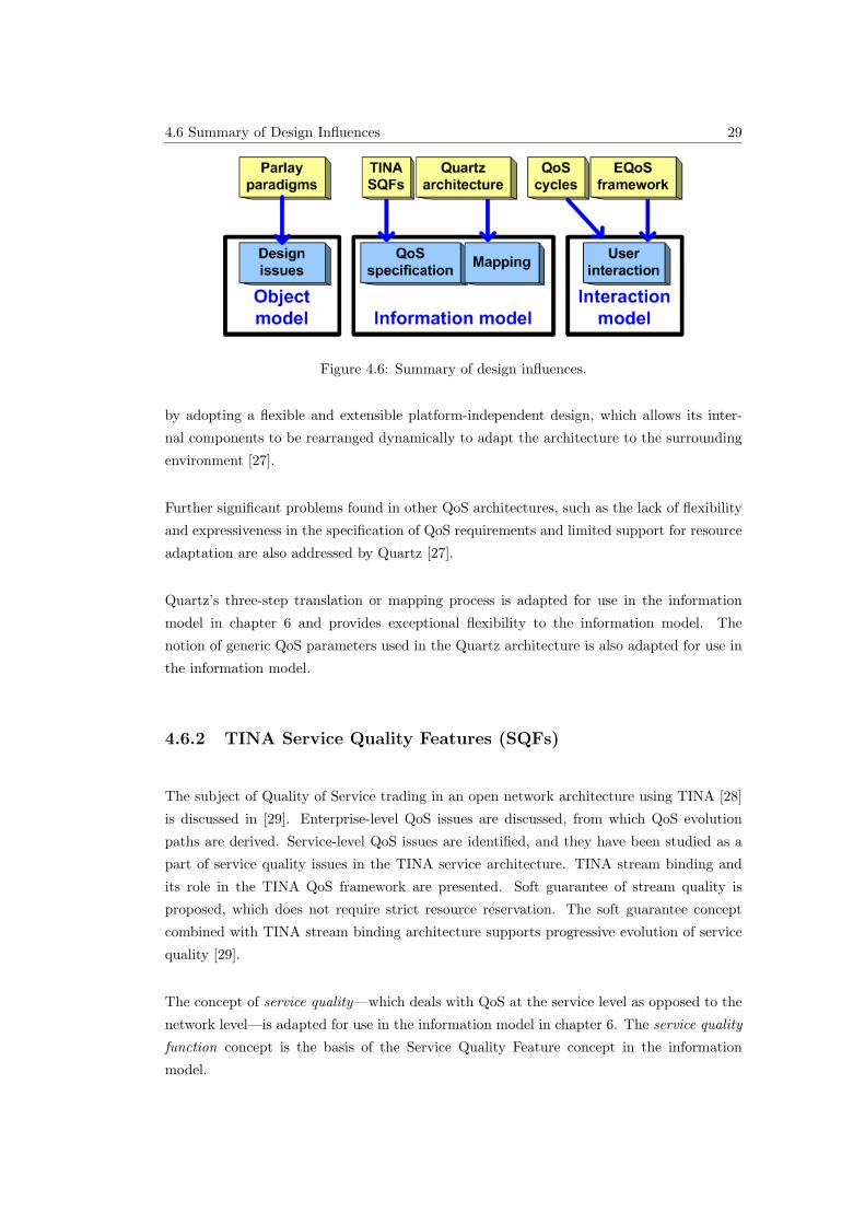
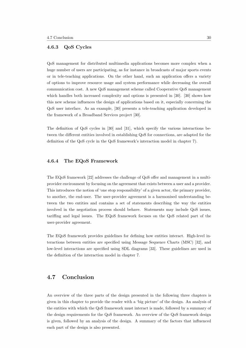
The concepts and factors that influenced the three parts of the design are summarised in
this section and illustrated in figure 4.6. The object model presented in chapter 5 is based
primarily on Parlay’s design paradigms which are presented in section 5.3. The remaining
four factors that influenced the various parts of the design are:
• the Quartz architecture: the basis of the mapping concept in the information model;
• TINA Service Quality Features: the source of the QoS specification concept in the
information model;
• QoS cycles: used for defining user interaction mechanisms in the interaction model;
and
• the EQoS framework: the basis of the user interaction concept in the interaction model.
These four factors and there influences on the various parts of the design are presented in
the following four sub-sections.
4.6.1 The Quartz Architecture
A description of a QoS architecture that provides support for QoS specification and enforce-
ment in heterogeneous distributed computing systems is presented in [27]. Quartz is able
to accommodate differences among diverse computing platforms and areas of application
4.6 Summary of Design Influences 29
Figure 4.6: Summary of design influences.
by adopting a flexible and extensible platform-independent design, which allows its inter-
nal components to be rearranged dynamically to adapt the architecture to the surrounding
environment [27].
Further significant problems found in other QoS architectures, such as the lack of flexibility
and expressiveness in the specification of QoS requirements and limited support for resource
adaptation are also addressed by Quartz [27].
Quartz’s three-step translation or mapping process is adapted for use in the information
model in chapter 6 and provides exceptional flexibility to the information model. The
notion of generic QoS parameters used in the Quartz architecture is also adapted for use in
the information model.
4.6.2 TINA Service Quality Features (SQFs)
The subject of Quality of Service trading in an open network architecture using TINA [28]
is discussed in [29]. Enterprise-level QoS issues are discussed, from which QoS evolution
paths are derived. Service-level QoS issues are identified, and they have been studied as a
part of service quality issues in the TINA service architecture. TINA stream binding and
its role in the TINA QoS framework are presented. Soft guarantee of stream quality is
proposed, which does not require strict resource reservation. The soft guarantee concept
combined with TINA stream binding architecture supports progressive evolution of service
quality [29].
The concept of service quality—which deals with QoS at the service level as opposed to the
network level—is adapted for use in the information model in chapter 6. The service quality
function concept is the basis of the Service Quality Feature concept in the information
model.
4.7 Conclusion 30
4.6.3 QoS Cycles
QoS management for distributed multimedia applications becomes more complex when a
huge number of users are participating, as for instance in broadcasts of major sports events
or in tele-teaching applications. On the other hand, such an application offers a variety
of options to improve resource usage and system performance while decreasing the overall
communication cost. A new QoS management scheme called Cooperative QoS management
which handles both increased complexity and options is presented in [30]. [30] shows how
this new scheme influences the design of applications based on it, especially concerning the
QoS user interface. As an example, [30] presents a tele-teaching application developed in
the framework of a Broadband Services project [30].
The definition of QoS cycles in [30] and [31], which specify the various interactions be-
tween the different entities involved in establishing QoS for connections, are adapted for the
definition of the QoS cycle in the QoS framework’s interaction model in chapter 7).
4.6.4 The EQoS Framework
The EQoS framework [22] addresses the challenge of QoS offer and management in a multi-
provider environment by focusing on the agreement that exists between a user and a provider.
This introduces the notion of ‘one stop responsibility’ of a given actor, the primary provider,
to another, the end-user. The user-provider agreement is a harmonised understanding be-
tween the two entities and contains a set of statements describing the way the entities
involved in the negotiation process should behave. Statements may include QoS issues,
tariffing and legal issues. The EQoS framework focuses on the QoS related part of the
user-provider agreement.
The EQoS framework provides guidelines for defining how entities interact. High-level in-
teractions between entities are specified using Message Sequence Charts (MSC) [32], and
low-level interactions are specified using SDL diagrams [33]. These guidelines are used in
the definition of the interaction model in chapter 7.
4.7 Conclusion
An overview of the three parts of the design presented in the following three chapters is
given in this chapter to provide the reader with a ‘big picture’ of the design. An analysis of
the entities with which the QoS framework must interact is made, followed by a summary of
the design requirements for the QoS framework. An overview of the QoS framework design
is given, followed by an analysis of the design. A summary of the factors that influenced
each part of the design is also presented.

4.7 Conclusion 31
The three parts of the design are presented in the following three chapters in more detail,
followed by a formal UML specification of the complete design in chapter 8. The details of
a software simulation of the design are summarised in chapter 9.
5.2 Design Requirements 32
Chapter 5
Design of the Object Model
5.1 Introduction
As mentioned in the design overview in chapter 4, the design of the QoS framework for
Parlay is divided into three distinct parts. This chapter presents the first part of the QoS
framework design, the Object Model. The Object Model defines:
• The entities or objects that make up the QoS framework, as well as
• The entities that the QoS framework entities interact with.
The design requirements for the object model are described in the following section (5.2).
One major design requirement identified is the need for the QoS framework to follow Par-
lay design paradigms. Section 5.3 therefore presents Parlay design paradigms for object
models.The QoS framework’s object model is based on these Parlay design paradigms. The
object model design is presented in section 5.4. An analysis of the object model is made in
section 5.6.
5.2 Design Requirements
The QoS framework must interact with applications to obtain QoS requests as well as the
CSM to fulfil QoS requests, as shown in section 4.2. The QoS framework is an extension of
the Parlay API. The object model for the QoS framework focuses on defining the objects
that make up the QoS framework as well as how the QoS framework objects fit into the
existing Parlay infrastructure, as shown in figure 5.1.
5.3 Parlay’s Design Paradigms 33
Figure 5.1: Required QoS framework object model.
Figure 5.2: Object-oriented design paradigms in Parlay.
The design of the QoS framework must be completely object-oriented, since it is a part of
Parlay which is itself object-oriented [4]. The general design paradigms of Parlay must also
be followed where possible with regard to object-oriented design.
Applicable examples of object-oriented design paradigms in Parlay that are followed in the
design of the QoS framework are described in the following section (5.3).
5.3 Design paradigms in Parlay used in the design of
the object model
This section contains a summary of design paradigms in Parlay that are used in the design of
the object model for the QoS framework. The following three existing Parlay object-oriented
design paradigms [4] are described in the following subsections and illustrated in figure 5.2:
5.3 Parlay’s Design Paradigms 34
Figure 5.3: Object model for call control service.
• Parlay’s Service Manager concept;
• Parlay’s Session model; and
• Callback interfaces.
Parlay’s object-oriented design paradigms are described using an example in the following
section (5.3.1). The three particular design paradigms are presented in the subsequent
sections.
It must be noted that although these design paradigms are mentioned in the Parlay speci-
fication overview [4], they are not singled out as distinguishing features in the various SCF
specifications ([11, 26] for example). These design paradigms are however used in the design
of the object model for the QoS framework in this report.
5.3.1 Parlay’s Object-Oriented Paradigm
The Parlay architecture is completely object-oriented [4]. The QoS framework is designed
to be a part of Parlay, and must therefore also be object-oriented. In addition, the QoS
framework must support both existing and future connection services.
An example of an object model for an existing connection service in Parlay is the call
control service illustrated in figure 5.3. Parlay’s call control service allows applications to
setup, modify and terminate call sessions in the underlying networks. A call object is used
to provide an abstraction of a call in the underlying networks. One call object is created in
the Parlay Gateway for each call an application participates in.
The various other objects in figure 5.3 are described in the following sub-sections.
5.3 Parlay’s Design Paradigms 35
Figure 5.4: The Service Manager Concept in Parlay’s Call Control SCF.
5.3.2 The Service Manager Concept
In Parlay, ‘for each application that uses an SCF, a new object is created to handle all
communication with the application in the Parlay Gateway. This object is referred to as
the Service Manager’ [4] for the SCF. This is based on a software pattern [34] known as the
Factory Pattern [35]. ‘The Service Manager creates any new objects in the SCF’ as required
by the application. The Service Manager and all the objects created by it are referred to as
the ‘service instance’ [4], illustrated in figure 5.4.
‘Once an application is granted access to an SCF by the Parlay Framework, the Framework
requests the SCF to create a new Service Manager. The reference to this Service Manager
is provided to the application. From this moment onwards the application can start using
the SCF’ by using the reference to the Service Manager [4].
The Call Control SCF’s service manager is called the Call Manager. The Call Control SCF
creates a new Call Manager object upon request, and returns a reference to this object, as
shown in figure 5.4. The reference to the Call Manager can then be used to create a new
Call object for every call it interacts with in the underlying networks. The Call Manager
together with all its created objects, termed Call objects, are collectively known as the
‘service instance’.
5.3.3 The Session Model Concept
A session is defined as ‘a series of interactions between two or more communication end
points that occur during the span of a single connection’ [4]. An example is all operations
to set-up, control, and tear-down a call. An object, called a session object in this report, is
typically created for each session, representing that particular session. Any changes to the
session are made by interacting with the session object.
5.3 Parlay’s Design Paradigms 36
Figure 5.5: Session model.
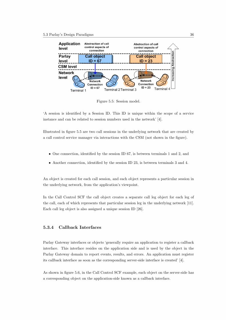
‘A session is identified by a Session ID. This ID is unique within the scope of a service
instance and can be related to session numbers used in the network’ [4].
Illustrated in figure 5.5 are two call sessions in the underlying network that are created by
a call control service manager via interactions with the CSM (not shown in the figure).
• One connection, identified by the session ID 67, is between terminals 1 and 2, and
• Another connection, identified by the session ID 23, is between terminals 3 and 4.
An object is created for each call session, and each object represents a particular session in
the underlying network, from the application’s viewpoint.
In the Call Control SCF the call object creates a separate call leg object for each leg of
the call, each of which represents that particular session leg in the underlying network [11].
Each call leg object is also assigned a unique session ID [26].
5.3.4 Callback Interfaces
Parlay Gateway interfaces or objects ‘generally require an application to register a callback
interface. This interface resides on the application side and is used by the object in the
Parlay Gateway domain to report events, results, and errors. An application must register
its callback interface as soon as the corresponding server-side interface is created’ [4].
As shown in figure 5.6, in the Call Control SCF example, each object on the server-side has
a corresponding object on the application-side known as a callback interface.
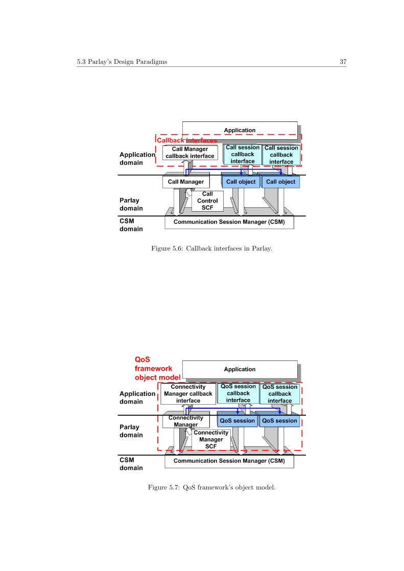
5.3 Parlay’s Design Paradigms 37
Figure 5.6: Callback interfaces in Parlay.
Figure 5.7: QoS framework’s object model.
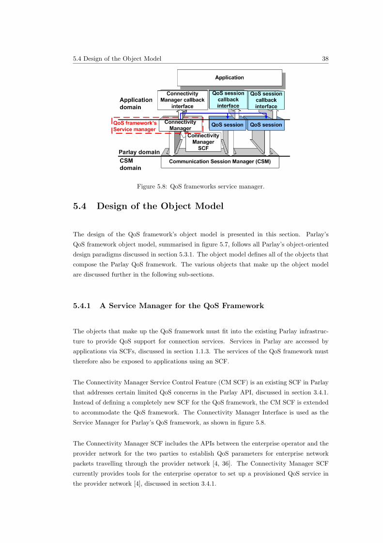
5.4 Design of the Object Model 38
Figure 5.8: QoS frameworks service manager.
5.4 Design of the Object Model
The design of the QoS framework’s object model is presented in this section. Parlay’s
QoS framework object model, summarised in figure 5.7, follows all Parlay’s object-oriented
design paradigms discussed in section 5.3.1. The object model defines all of the objects that
compose the Parlay QoS framework. The various objects that make up the object model
are discussed further in the following sub-sections.
5.4.1 A Service Manager for the QoS Framework
The objects that make up the QoS framework must fit into the existing Parlay infrastruc-
ture to provide QoS support for connection services. Services in Parlay are accessed by
applications via SCFs, discussed in section 1.1.3. The services of the QoS framework must
therefore also be exposed to applications using an SCF.
The Connectivity Manager Service Control Feature (CM SCF) is an existing SCF in Parlay
that addresses certain limited QoS concerns in the Parlay API, discussed in section 3.4.1.
Instead of defining a completely new SCF for the QoS framework, the CM SCF is extended
to accommodate the QoS framework. The Connectivity Manager Interface is used as the
Service Manager for Parlay’s QoS framework, as shown in figure 5.8.
The Connectivity Manager SCF includes the APIs between the enterprise operator and the
provider network for the two parties to establish QoS parameters for enterprise network
packets travelling through the provider network [4, 36]. The Connectivity Manager SCF
currently provides tools for the enterprise operator to set up a provisioned QoS service in
the provider network [4], discussed in section 3.4.1.
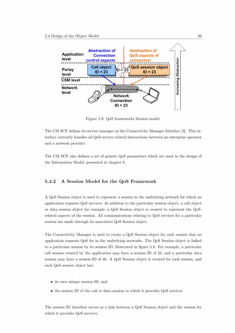
5.4 Design of the Object Model 39
Figure 5.9: QoS frameworks Session model.
The CM SCF defines its service manager as the Connectivity Manager Interface [3]. This in-
terface currently handles all QoS-service related interactions between an enterprise operator
and a network provider.
The CM SCF also defines a set of generic QoS parameters which are used in the design of
the Information Model, presented in chapter 6.
5.4.2 A Session Model for the QoS Framework
A QoS Session object is used to represent a session in the underlying network for which an
application requests QoS services. In addition to the particular session object, a call object
or data session object for example, a QoS Session object is created to represent the QoS-
related aspects of the session. All communications relating to QoS services for a particular
session are made through its associated QoS Session object.
The Connectivity Manager is used to create a QoS Session object for each session that an
application requests QoS for in the underlying networks. The QoS Session object is linked
to a particular session by its session ID, illustrated in figure 5.9. For example, a particular
call session created by the application may have a session ID of 23, and a particular data
session may have a session ID of 46. A QoS Session object is created for each session, and
each QoS session object has:
• its own unique session ID, and
• the session ID of the call or data session to which it provides QoS services
The session ID therefore serves as a link between a QoS Session object and the session for
which it provides QoS services.
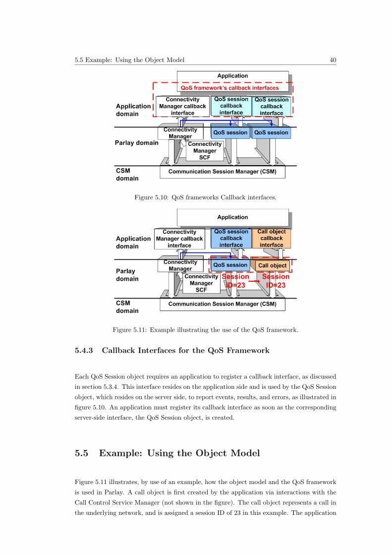
5.5 Example: Using the Object Model 40
Figure 5.10: QoS frameworks Callback interfaces.
Figure 5.11: Example illustrating the use of the QoS framework.
5.4.3 Callback Interfaces for the QoS Framework
Each QoS Session object requires an application to register a callback interface, as discussed
in section 5.3.4. This interface resides on the application side and is used by the QoS Session
object, which resides on the server side, to report events, results, and errors, as illustrated in
figure 5.10. An application must register its callback interface as soon as the corresponding
server-side interface, the QoS Session object, is created.
5.5 Example: Using the Object Model
Figure 5.11 illustrates, by use of an example, how the object model and the QoS framework
is used in Parlay. A call object is first created by the application via interactions with the
Call Control Service Manager (not shown in the figure). The call object represents a call in
the underlying network, and is assigned a session ID of 23 in this example. The application
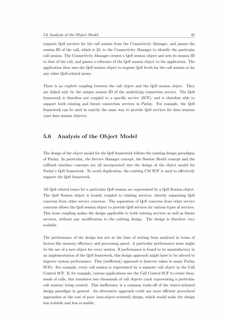
5.6 Analysis of the Object Model 41
requests QoS services for the call session from the Connectivity Manager, and passes the
session ID of the call, which is 23, to the Connectivity Manager to identify the particular
call session. The Connectivity Manager creates a QoS session object and sets its session ID
to that of the call, and passes a reference of the QoS session object to the application. The
application then uses the QoS session object to request QoS levels for the call session or for
any other QoS-related issues.
There is no explicit coupling between the call object and the QoS session object. They
are linked only by the unique session ID of the underlying connection service. The QoS
framework is therefore not coupled to a specific service (SCF), and is therefore able to
support both existing and future connection services in Parlay. For example, the QoS
framework can be used in exactly the same way to provide QoS services for data sessions
(and data session objects).
5.6 Analysis of the Object Model
The design of the object model for the QoS framework follows the existing design paradigms
of Parlay. In particular, the Service Manager concept, the Session Model concept and the
callback interface concepts are all incorporated into the design of the object model for
Parlay’s QoS framework. To avoid duplication, the existing CM SCF is used to effectively
support the QoS framework.
All QoS related issues for a particular QoS session are represented by a QoS Session object.
The QoS Session object is loosely coupled to existing services, thereby separating QoS
concerns from other service concerns. The separation of QoS concerns from other service
concerns allows the QoS session object to provide QoS services for various types of services.
This loose coupling makes the design applicable to both existing services as well as future
services, without any modification to the existing design. The design is therefore very
scalable.
The performance of the design has not at the time of writing been analysed in terms of
factors like memory efficiency and processing speed. A particular performance issue might
be the use of a new object for every session. If performance is found to be unsatisfactory in
an implementation of the QoS framework, this design approach might have to be altered to
improve system performance. This (inefficient) approach is however taken in many Parlay
SCFs. For example, every call session is represented by a separate call object in the Call
Control SCF. If, for example, various applications use the Call Control SCF to create thou-
sands of calls, this translates into thousands of call objects (each representing a particular
call session) being created. This inefficiency is a common trade-off of the object-oriented
design paradigm in general. An alternative approach could use more efficient procedural
approaches at the cost of poor (non-object-oriented) design, which would make the design
less scalable and less re-usable.
5.7 Conclusion 42
5.7 Conclusion
One part of the design of Parlay’s QoS framework is presented in this chapter – the ob-
ject model. The design of the object model incorporates various existing Parlay design
paradigms, including the Service Manager concept, the Session Model concept, and the
callback interface concept. The Connectivity Manager SCF’s service manager, called the
Connectivity Manager, is used as the service manager for the QoS framework. The Connec-
tivity Manager is used to create a QoS Session object that represents all the QoS related
issues with regard to a particular service session.
The design is very scalable, due to the loose coupling between QoS-related issues and other
services. This is accomplished by the introduction of a QoS session object for each service
session, which handles all QoS related issues for that particular service session. This makes
the design of the object model applicable to both existing and future Parlay services.
Performance related issues have not been addressed in this report. If the performance of the
QoS framework is found to be unsatisfactory, the QoS session object concept might require
review to improve the performance of the QoS framework.
This chapter defines the objects that compose the QoS framework. The following chapter
(6) defines the information model for the QoS framework, which describes what information
is required by the objects. The third and last part of the design presented in chapter 7
defines the interaction model for the QoS framework, which describes how the objects pass
information to each other.
The three parts of the design, including the one presented in this chapter, are composed
into a single formal UML specification in chapter 8.
6.2 Specification of the Type of Traffic 43
Chapter 6
Design of the Information Model
6.1 Introduction
As mentioned in the design overview in chapter 4, the design of the QoS framework for
Parlay is divided into three distinct parts. This chapter presents the second part of the QoS
framework design, the Information Model.
The focus in the information model is primarily on the specification of QoS-related informa-
tion in the QoS framework. There are two types of QoS specification required for connection
services in the Parlay context, namely, the specification of:
• The type of traffic that must be carried by the underlying networks – to allow certain
networks to optimise the transport of traffic across the network resources [2], and
• The level of QoS for connection services in the underlying networks.
The information model is divided into two parts, each of which describe one of the above-
mentioned specification types in the QoS framework. The design of the part that deals with
the specification of the type of traffic is described in the following section (6.2). The design
of the part that deals with the specification of the level of QoS is presented in section 6.3.
6.2 Specification of the Type of Traffic
This section presents the part of the design of the information model that deals with the
specification of the type of traffic in the underlying networks. The design requirements are
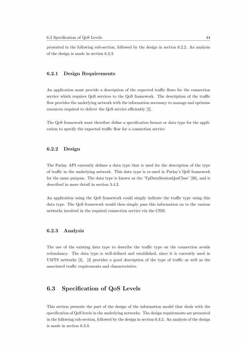
6.3 Specification of QoS Levels 44
presented in the following sub-section, followed by the design in section 6.2.2. An analysis
of the design is made in section 6.2.3.
6.2.1 Design Requirements
An application must provide a description of the expected traffic flows for the connection
service which requires QoS services to the QoS framework. The description of the traffic
flow provides the underlying network with the information necessary to manage and optimise
resources required to deliver the QoS service efficiently [2].
The QoS framework must therefore define a specification format or data type for the appli-
cation to specify the expected traffic flow for a connection service.
6.2.2 Design
The Parlay API currently defines a data type that is used for the description of the type
of traffic in the underlying network. This data type is re-used in Parlay’s QoS framework
for the same purpose. The data type is known as the ‘TpDataSessionQosClass’ [26], and is
described in more detail in section 3.4.2.
An application using the QoS framework could simply indicate the traffic type using this
data type. The QoS framework would then simply pass this information on to the various
networks involved in the required connection service via the CSM.
6.2.3 Analysis
The use of the existing data type to describe the traffic type on the connection avoids
redundancy. The data type is well-defined and established, since it is currently used in
UMTS networks [2]. [2] provides a good description of the type of traffic as well as the
associated traffic requirements and characteristics.
6.3 Specification of QoS Levels
This section presents the part of the design of the information model that deals with the
specification of QoS levels in the underlying networks. The design requirements are presented
in the following sub-section, followed by the design in section 6.3.2. An analysis of the design
is made in section 6.3.3.
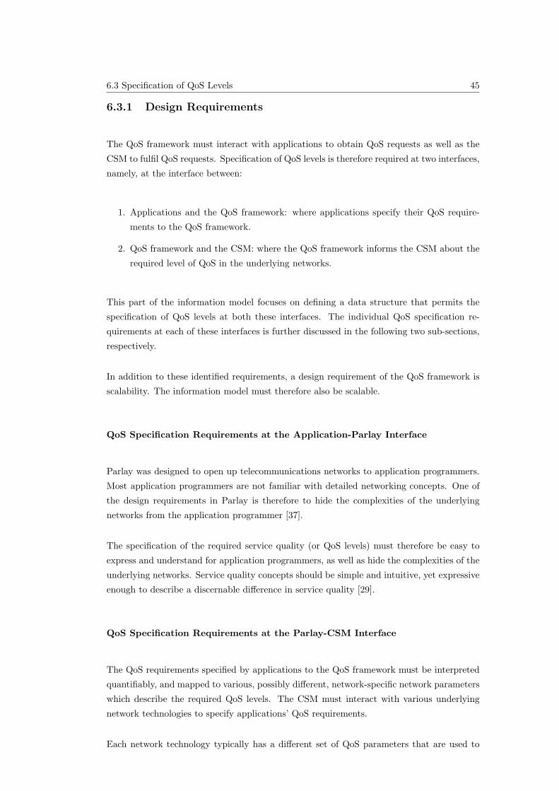
6.3 Specification of QoS Levels 45
6.3.1 Design Requirements
The QoS framework must interact with applications to obtain QoS requests as well as the
CSM to fulfil QoS requests. Specification of QoS levels is therefore required at two interfaces,
namely, at the interface between:
1. Applications and the QoS framework: where applications specify their QoS require-
ments to the QoS framework.
2. QoS framework and the CSM: where the QoS framework informs the CSM about the
required level of QoS in the underlying networks.
This part of the information model focuses on defining a data structure that permits the
specification of QoS levels at both these interfaces. The individual QoS specification re-
quirements at each of these interfaces is further discussed in the following two sub-sections,
respectively.
In addition to these identified requirements, a design requirement of the QoS framework is
scalability. The information model must therefore also be scalable.
QoS Specification Requirements at the Application-Parlay Interface
Parlay was designed to open up telecommunications networks to application programmers.
Most application programmers are not familiar with detailed networking concepts. One of
the design requirements in Parlay is therefore to hide the complexities of the underlying
networks from the application programmer [37].
The specification of the required service quality (or QoS levels) must therefore be easy to
express and understand for application programmers, as well as hide the complexities of the
underlying networks. Service quality concepts should be simple and intuitive, yet expressive
enough to describe a discernable difference in service quality [29].
QoS Specification Requirements at the Parlay-CSM Interface
The QoS requirements specified by applications to the QoS framework must be interpreted
quantifiably, and mapped to various, possibly different, network-specific network parameters
which describe the required QoS levels. The CSM must interact with various underlying
network technologies to specify applications’ QoS requirements.
Each network technology typically has a different set of QoS parameters that are used to
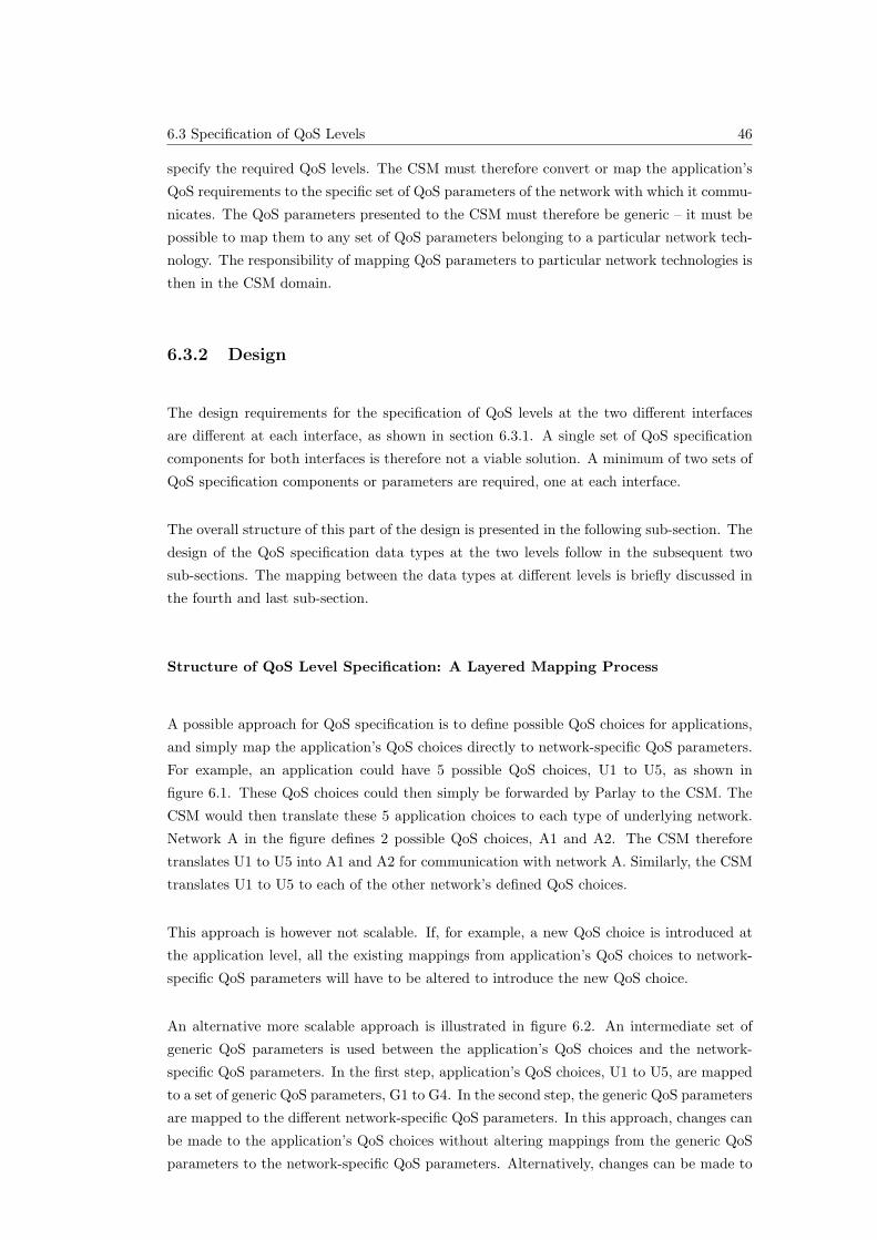
6.3 Specification of QoS Levels 46
specify the required QoS levels. The CSM must therefore convert or map the application’s
QoS requirements to the specific set of QoS parameters of the network with which it commu-
nicates. The QoS parameters presented to the CSM must therefore be generic – it must be
possible to map them to any set of QoS parameters belonging to a particular network tech-
nology. The responsibility of mapping QoS parameters to particular network technologies is
then in the CSM domain.
6.3.2 Design
The design requirements for the specification of QoS levels at the two different interfaces
are different at each interface, as shown in section 6.3.1. A single set of QoS specification
components for both interfaces is therefore not a viable solution. A minimum of two sets of
QoS specification components or parameters are required, one at each interface.
The overall structure of this part of the design is presented in the following sub-section. The
design of the QoS specification data types at the two levels follow in the subsequent two
sub-sections. The mapping between the data types at different levels is briefly discussed in
the fourth and last sub-section.
Structure of QoS Level Specification: A Layered Mapping Process
A possible approach for QoS specification is to define possible QoS choices for applications,
and simply map the application’s QoS choices directly to network-specific QoS parameters.
For example, an application could have 5 possible QoS choices, U1 to U5, as shown in
figure 6.1. These QoS choices could then simply be forwarded by Parlay to the CSM. The
CSM would then translate these 5 application choices to each type of underlying network.
Network A in the figure defines 2 possible QoS choices, A1 and A2. The CSM therefore
translates U1 to U5 into A1 and A2 for communication with network A. Similarly, the CSM
translates U1 to U5 to each of the other network’s defined QoS choices.
This approach is however not scalable. If, for example, a new QoS choice is introduced at
the application level, all the existing mappings from application’s QoS choices to network-
specific QoS parameters will have to be altered to introduce the new QoS choice.
An alternative more scalable approach is illustrated in figure 6.2. An intermediate set of
generic QoS parameters is used between the application’s QoS choices and the network-
specific QoS parameters. In the first step, application’s QoS choices, U1 to U5, are mapped
to a set of generic QoS parameters, G1 to G4. In the second step, the generic QoS parameters
are mapped to the different network-specific QoS parameters. In this approach, changes can
be made to the application’s QoS choices without altering mappings from the generic QoS
parameters to the network-specific QoS parameters. Alternatively, changes can be made to
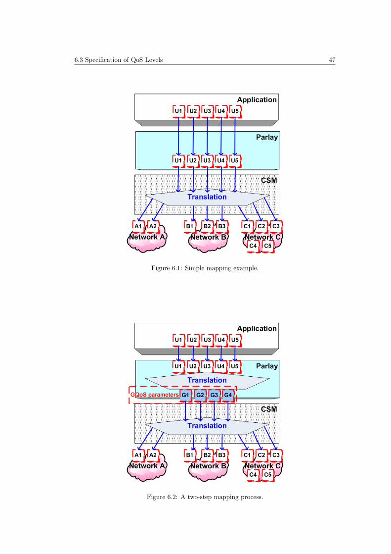
6.3 Specification of QoS Levels 47
Figure 6.1: Simple mapping example.
Figure 6.2: A two-step mapping process.
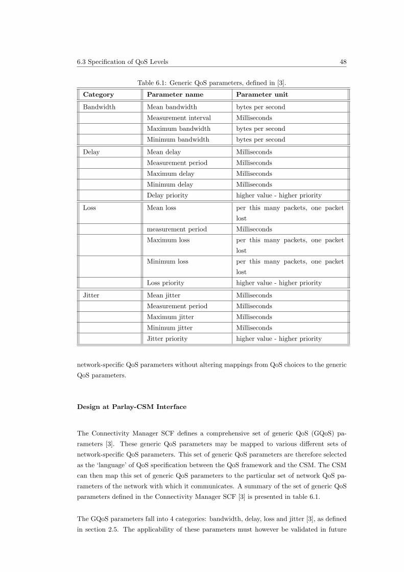
6.3 Specification of QoS Levels 48
Table 6.1: Generic QoS parameters, defined in [3].
Category Parameter name Parameter unit
Bandwidth Mean bandwidth bytes per second
Measurement interval Milliseconds
Maximum bandwidth bytes per second
Minimum bandwidth bytes per second
Delay Mean delay Milliseconds
Measurement period Milliseconds
Maximum delay Milliseconds
Minimum delay Milliseconds
Delay priority higher value - higher priority
Loss Mean loss per this many packets, one packet
lost
measurement period Milliseconds
Maximum loss per this many packets, one packet
lost
Minimum loss per this many packets, one packet
lost
Loss priority higher value - higher priority
Jitter Mean jitter Milliseconds
Measurement period Milliseconds
Maximum jitter Milliseconds
Minimum jitter Milliseconds
Jitter priority higher value - higher priority
network-specific QoS parameters without altering mappings from QoS choices to the generic
QoS parameters.
Design at Parlay-CSM Interface
The Connectivity Manager SCF defines a comprehensive set of generic QoS (GQoS) pa-
rameters [3]. These generic QoS parameters may be mapped to various different sets of
network-specific QoS parameters. This set of generic QoS parameters are therefore selected
as the ‘language’ of QoS specification between the QoS framework and the CSM. The CSM
can then map this set of generic QoS parameters to the particular set of network QoS pa-
rameters of the network with which it communicates. A summary of the set of generic QoS
parameters defined in the Connectivity Manager SCF [3] is presented in table 6.1.
The GQoS parameters fall into 4 categories: bandwidth, delay, loss and jitter [3], as defined
in section 2.5. The applicability of these parameters must however be validated in future
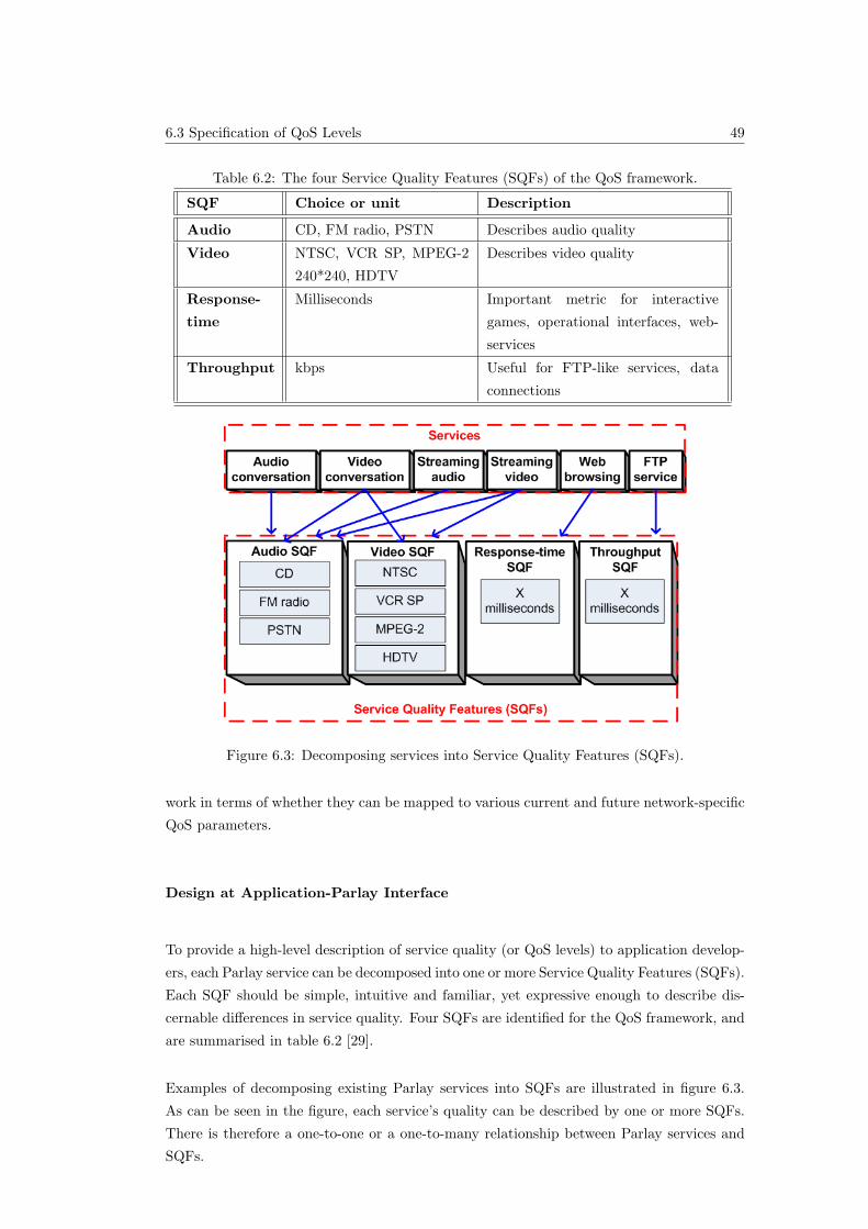
6.3 Specification of QoS Levels 49
Table 6.2: The four Service Quality Features (SQFs) of the QoS framework.
SQF Choice or unit Description
Audio CD, FM radio, PSTN Describes audio quality
Video NTSC, VCR SP, MPEG-2
240*240, HDTV
Describes video quality
Response-
time
Milliseconds Important metric for interactive
games, operational interfaces, web-
services
Throughput kbps Useful for FTP-like services, data
connections
Figure 6.3: Decomposing services into Service Quality Features (SQFs).
work in terms of whether they can be mapped to various current and future network-specific
QoS parameters.
Design at Application-Parlay Interface
To provide a high-level description of service quality (or QoS levels) to application develop-
ers, each Parlay service can be decomposed into one or more Service Quality Features (SQFs).
Each SQF should be simple, intuitive and familiar, yet expressive enough to describe dis-
cernable differences in service quality. Four SQFs are identified for the QoS framework, and
are summarised in table 6.2 [29].
Examples of decomposing existing Parlay services into SQFs are illustrated in figure 6.3.
As can be seen in the figure, each service’s quality can be described by one or more SQFs.
There is therefore a one-to-one or a one-to-many relationship between Parlay services and
SQFs.
6.3 Specification of QoS Levels 50
Mapping SQFs to Generic QoS Parameters
The mapping of SQFs to GQoS parameters is outside the scope of this report, but must be
addressed in future work. This section discusses at a high-level a few guidelines for mapping
SQFs to GQoS parameters.
The mapping from an SQF to generic QoS parameters depends on two primary factors:
• The type of traffic on the connection – specified by the QoS class, discussed in section
6.2, and
• The level of quality chosen for the particular SQF by an application.
For example, an application might use one of Parlay’s Call Control services, like the Generic
Call Control service [11]. The application would discover (by enquiring from the QoS frame-
work) that the call control service has only an audio SQF (since it is a voice only call).
The application could choose CD quality for the call, for example. The QoS framework
would then convert this QoS choice to a set of levels for each of the GQoS parameters. For
example, the SQFs could be mapped to the following primary GQoS parameters:
• Bandwidth: 2.3 kilobits per second;
• Delay: 3 milliseconds;
• Jitter: 0.1 milliseconds; and
• Loss: 4 packets per 1000.
The GQoS parameters would be passed by the QoS framework to the CSM, which would
in turn convert these GQoS parameters to the set of network-specific parameters of each
network with which it communicates.
The mapping of the SQFs to the generic QoS parameters is not unique, since the level of the
SQFs are not completely objective. For example, one implementation of the mapping might
map CD quality to a bandwidth of 2.1 kilobits per second, while another implementation of
the mapping might map CD quality to a bandwidth of 2.0 kilobits per second. The mapping
to each GQoS parameter from the same SQF level could potentially be different for each
implementation of this information model. This mapping process is complex and outside
the scope of this report, but must be further investigated in future work.
6.4 Conclusion 51
6.3.3 Analysis
The decomposition of Parlay services using Service Quality Features (SQFs) makes the
description of the required QoS level by an application developer a simple, intuitive and
familiar process.
The use of the existing generic QoS parameters defined in the Connectivity Manager SCF
avoids redundancy in the information model, building on existing design concepts in the
Parlay API. The feasibility of these parameters must however be verified. In particular,
future work involves verifying whether these parameters are:
• Complete: whether the parameters take advantage of various network features, and
• Applicable: whether the parameters can be mapped, at least to some degree, to various
different network-specific QoS parameters.
The use of a two-step layered mapping process makes the information model more scalable by
reducing the overall number of mappings required in the model. The mappings from SQFs
to the generic QoS parameters are a complex process, and must be further investigated in
future work.
6.4 Conclusion
The second part of three parts of the design of Parlay’s QoS framework is presented in this
chapter – the Information Model. The information model is divided into two distinct parts:
describing the type of traffic, and describing the required QoS.
The description of the type of traffic is made using an existing data structure—‘TpDataSessionQosClass’—
which is defined in [2]. The data type essentially defines four QoS classes, each of which
describes a particular type of traffic.
The description of the required service quality level is simplified for the application program-
mer by decomposing Parlay services into four simple, intuitive and familiar Service Quality
Features (SQFs): Audio quality, Video quality, response-time and throughput.
The description of the required service quality level at the CSM level is made using existing
generic QoS parameters, defined in [3]. The feasibility of this set of parameters must however
be verified in terms of completeness and applicability in future work.
The two-step mapping process makes the design of the information more scalable, and
reduces the number of mappings required in the model. The mappings between SQFs and
6.4 Conclusion 52
generic QoS parameters are complex and must be further investigated in future work. In
addition, the mappings from the generic QoS parameters to network-specific QoS parameters
must be further investigated – this task is in the scope of the CSM.
The previous chapter defined the objects that make up the QoS framework. This chapter
defines the types of information that are required by the objects in the QoS framework to
specify QoS-related information. The third and last part of the design, presented in the
following chapter 7, defines the interaction model for objects in the QoS framework, which
describes exactly how the objects pass information to each other.
The three parts of the design, including the one presented in this chapter, are composed
into a single formal UML specification in chapter 8.
7.2 Design Requirements 53
Chapter 7
Design of the Interaction Model
7.1 Introduction
As mentioned in the design overview in chapter 4), the design of the QoS framework for
Parlay is divided into three distinct parts. This chapter presents the final part of the QoS
framework design, the Interaction Model. The Interaction Model defines:
• How entities in the QoS framework may interact with each other, and
• How entities in the QoS framework may interact with external entities, like applications
and the CSM.
These definitions provide the reader with a practical understanding of how the QoS frame-
work presented in this report operates. The design requirements for the interaction model
are described in the following section (7.2). The design of the interaction model is presented
in section 7.3, followed by an analysis of the design in section 7.4.
7.2 Design Requirements
The QoS framework must interact with applications as well as the CSM, defined in section
1.1.3, to perform the following functions, illustrated in figure 7.1:
• Initiation: The application must initially request to use QoS services from the QoS
framework;
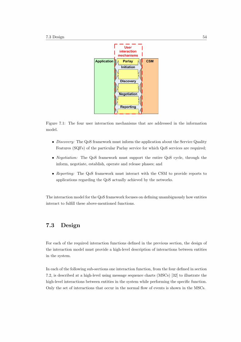
7.3 Design 54
Figure 7.1: The four user interaction mechanisms that are addressed in the information
model.
• Discovery: The QoS framework must inform the application about the Service Quality
Features (SQFs) of the particular Parlay service for which QoS services are required;
• Negotiation: The QoS framework must support the entire QoS cycle, through the
inform, negotiate, establish, operate and release phases; and
• Reporting: The QoS framework must interact with the CSM to provide reports to
applications regarding the QoS actually achieved by the networks.
The interaction model for the QoS framework focuses on defining unambiguously how entities
interact to fulfill these above-mentioned functions.
7.3 Design
For each of the required interaction functions defined in the previous section, the design of
the interaction model must provide a high-level description of interactions between entities
in the system.
In each of the following sub-sections one interaction function, from the four defined in section
7.2, is described at a high-level using message sequence charts (MSCs) [32] to illustrate the
high-level interactions between entities in the system while performing the specific function.
Only the set of interactions that occur in the normal flow of events is shown in the MSCs.
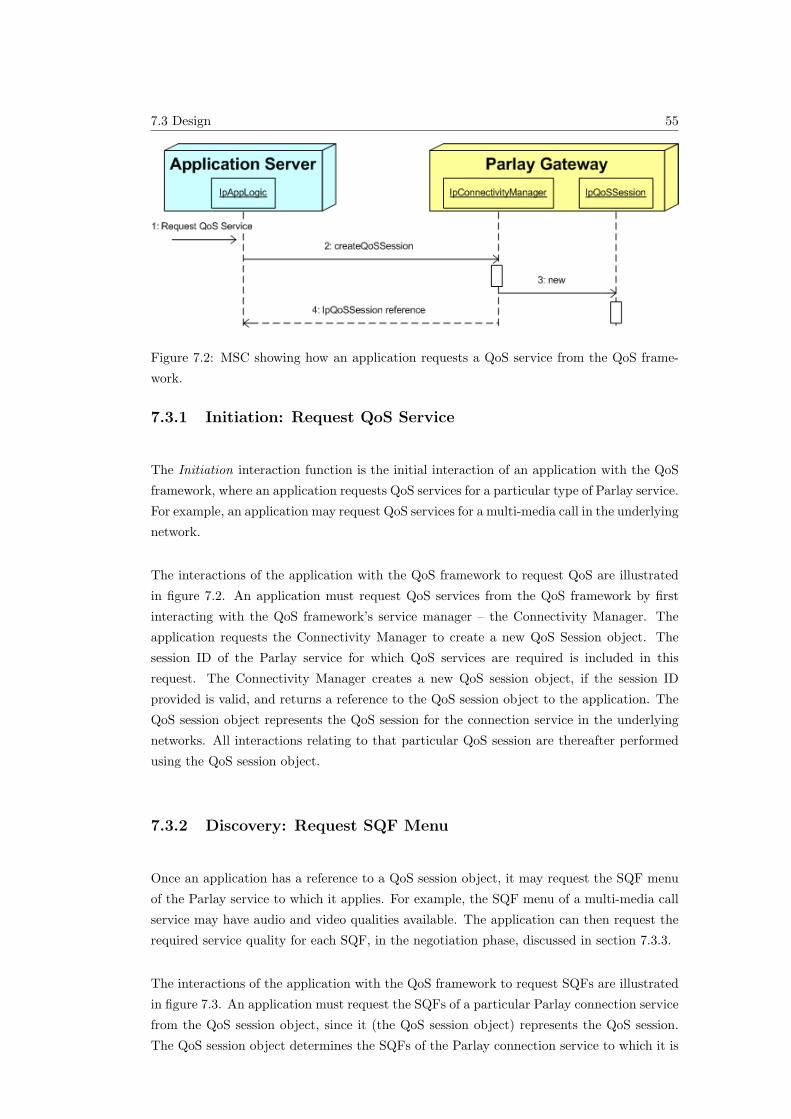
7.3 Design 55
Figure 7.2: MSC showing how an application requests a QoS service from the QoS frame-
work.
7.3.1 Initiation: Request QoS Service
The Initiation interaction function is the initial interaction of an application with the QoS
framework, where an application requests QoS services for a particular type of Parlay service.
For example, an application may request QoS services for a multi-media call in the underlying
network.
The interactions of the application with the QoS framework to request QoS are illustrated
in figure 7.2. An application must request QoS services from the QoS framework by first
interacting with the QoS framework’s service manager – the Connectivity Manager. The
application requests the Connectivity Manager to create a new QoS Session object. The
session ID of the Parlay service for which QoS services are required is included in this
request. The Connectivity Manager creates a new QoS session object, if the session ID
provided is valid, and returns a reference to the QoS session object to the application. The
QoS session object represents the QoS session for the connection service in the underlying
networks. All interactions relating to that particular QoS session are thereafter performed
using the QoS session object.
7.3.2 Discovery: Request SQF Menu
Once an application has a reference to a QoS session object, it may request the SQF menu
of the Parlay service to which it applies. For example, the SQF menu of a multi-media call
service may have audio and video qualities available. The application can then request the
required service quality for each SQF, in the negotiation phase, discussed in section 7.3.3.
The interactions of the application with the QoS framework to request SQFs are illustrated
in figure 7.3. An application must request the SQFs of a particular Parlay connection service
from the QoS session object, since it (the QoS session object) represents the QoS session.
The QoS session object determines the SQFs of the Parlay connection service to which it is
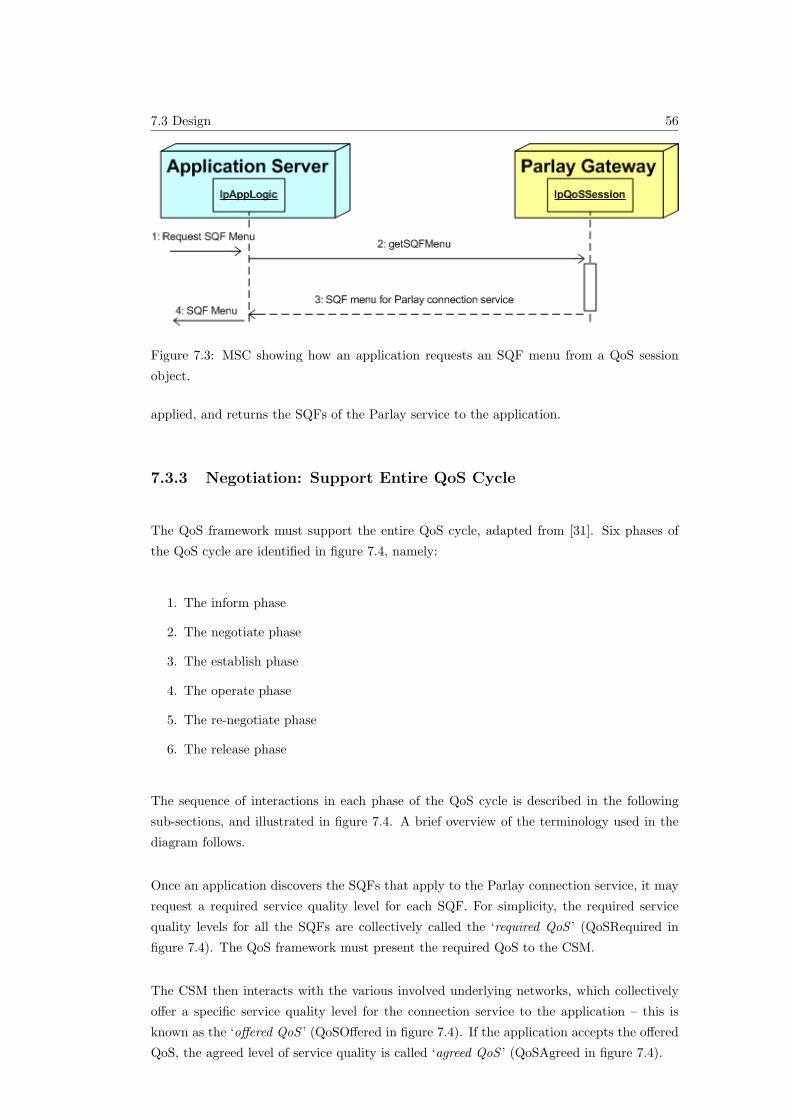
7.3 Design 56
Figure 7.3: MSC showing how an application requests an SQF menu from a QoS session
object.
applied, and returns the SQFs of the Parlay service to the application.
7.3.3 Negotiation: Support Entire QoS Cycle
The QoS framework must support the entire QoS cycle, adapted from [31]. Six phases of
the QoS cycle are identified in figure 7.4, namely:
1. The inform phase
2. The negotiate phase
3. The establish phase
4. The operate phase
5. The re-negotiate phase
6. The release phase
The sequence of interactions in each phase of the QoS cycle is described in the following
sub-sections, and illustrated in figure 7.4. A brief overview of the terminology used in the
diagram follows.
Once an application discovers the SQFs that apply to the Parlay connection service, it may
request a required service quality level for each SQF. For simplicity, the required service
quality levels for all the SQFs are collectively called the ‘required QoS ’ (QoSRequired in
figure 7.4). The QoS framework must present the required QoS to the CSM.
The CSM then interacts with the various involved underlying networks, which collectively
offer a specific service quality level for the connection service to the application – this is
known as the ‘offered QoS ’ (QoSOffered in figure 7.4). If the application accepts the offered
QoS, the agreed level of service quality is called ‘agreed QoS ’ (QoSAgreed in figure 7.4).
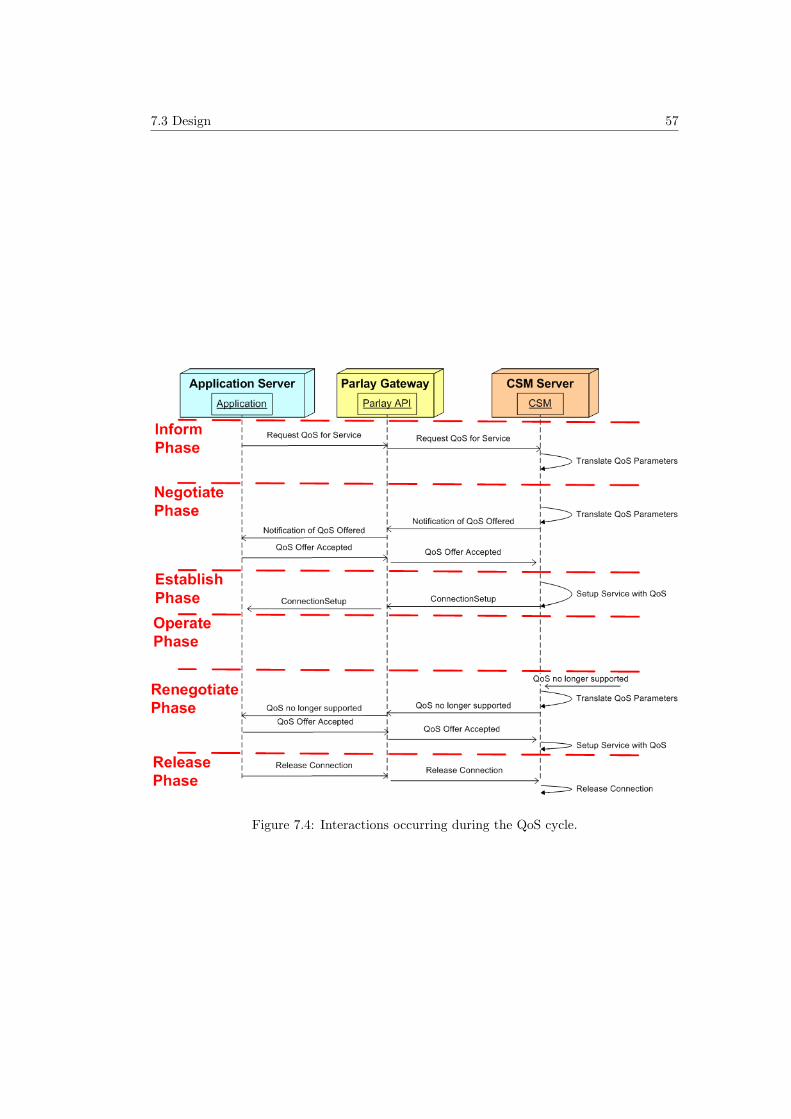
7.3 Design 57
Figure 7.4: Interactions occurring during the QoS cycle.
7.3 Design 58
Inform phase
To start the negotiation process, an application must first request the required QoS from
the QoS session object. The QoS session object converts the QoS request from SQF form
to generic QoS parameter form. The QoS session object forwards the application’s request
to the CSM. The CSM converts the QoS request from generic QoS form to network-specific
QoS form. The CSM forwards the application’s request to the various networks involved.
Negotiate phase
The various networks involved forward their offered QoS to the CSM. The CSM converts the
QoS offered from network-specific QoS form to generic QoS form. The CSM forwards the
QoS offered by the networks to the QoS session object. The QoS session object converts the
QoS offered from the generic QoS form to the SQF form. The QoS session object forwards
the QoS offered by the networks to the application. The application decides to accept the
QoS offered, and forwards a message to the QoS session object to indicate acceptance of the
QoS offer. The QoS session object forwards the acceptance message to the CSM.
Establish phase
The CSM interacts with the various networks involved to setup the required QoS service in
the underlying networks. This typically involves the reservation of resources in the underly-
ing networks for the connection. The various networks involved confirm the establishment
of the QoS service to the CSM. The CSM forwards the confirmation message to the QoS
session object. The QoS session object forwards the confirmation message to the application.
Operate phase
In this phase, the QoS service is operating in the underlying networks, and there are no
interactions between the entities.
Re-negotiate phase
One or more networks involved in the QoS service inform the CSM that the previously
agreed upon QoS can no longer be supported. The new QoS offered is also forwarded to
the CSM. The CSM converts the QoS offered from network-specific QoS form to generic
QoS form. The CSM forwards the QoS offered by the networks to the QoS session object.
The QoS session object converts the QoS offered from the generic QoS form to the SQF
7.4 Analysis 59
form. The QoS session object forwards the QoS offered by the networks to the application.
The application decides to accept the QoS offered, and forwards a message to the QoS
session object to indicate acceptance of the QoS offer. The QoS session object forwards the
acceptance message to the CSM. The establish and operate phases follow once more.
Release phase
The application requests a release of the QoS connection from the QoS session object. The
QoS session object forwards the release request to the CSM. The CSM interacts with the
various networks involved to release the connection. The networks can then release the
resources that were reserved for the QoS connection.
7.3.4 Reporting: Report Achieved QoS
During the operate phase of the QoS cycle or shortly after the release phase, the application
may request a report of the actual achieved QoS in the underlying networks, if this request
is supported in the underlying network. The typical interactions between entities in this
scenario are illustrated in figure 7.5, and described in the following paragraph.
The application puts a request forward to the QoS session object for reports. The QoS
session object forwards this request to the CSM. The CSM forwards the request to the
various networks involved in the QoS service. If the request is supported in the network, the
network indicates the actual achieved QoS to the CSM in the network-specific QoS form.
The CSM converts the QoS achieved from network-specific QoS form to generic QoS form.
The CSM forwards the QoS achieved by the networks to the QoS session object. The QoS
session object converts the QoS achieved from the generic QoS form to the SQF form. The
QoS session object forwards the QoS achieved by the networks to the application.
7.4 Analysis
The design of the Interaction Model for the QoS framework defines on a high-level how
the various entities in the QoS framework interact with each other as well as with external
entities, namely the applications and the CSM.
The interaction model supports the entire QoS cycle through the inform, negotiate, estab-
lish, operate, re-negotiate and release phases. It also supports the various other required
functions.
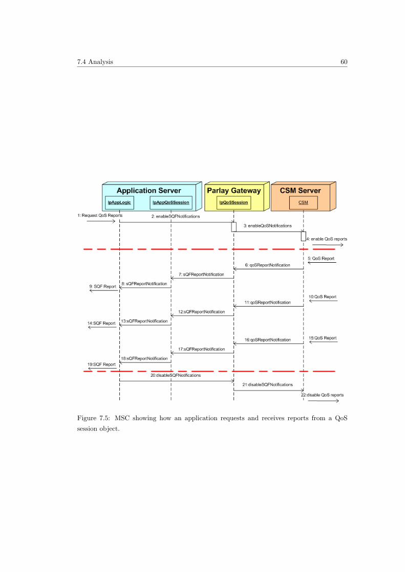
7.4 Analysis 60
Figure 7.5: MSC showing how an application requests and receives reports from a QoS
session object.
7.5 Conclusion 61
7.5 Conclusion
One part of the design of Parlay’s QoS framework is presented in this chapter – the Inter-
action Model. The design of the Interaction Model defines on a high-level how entities that
compose the QoS framework interact with each other as well as with external entities.
The Message Sequence Charts (MSCs) are useful in defining the required functions or meth-
ods of each entity (performed in the next chapter – in the UML Specification).
The interactions of the CSM with the various underlying network technologies identified in
this chapter may be useful in designing the QoS-related aspects of the CSM, but is outside
the scope of this work.
Chapter 5 defines the objects that compose the QoS framework. The previous chapter (6)
defines the information model for the QoS framework, which describes what information is
required by the objects. The third and last part of the design, presented in this chapter,
defines the interaction model for the QoS framework, which describes how the objects inter-
act with each other. The following chapter (8) presents a formal, technology-independent
specification of all three parts of the design using the Unified Modelling Language (UML).
8.2 Requirements of UML Specifications 62
Chapter 8
UML Specification of the QoS
Framework
8.1 Introduction
This chapter presents a formal, technology-independent specification of Parlay’s QoS frame-
work for connection services. The UML specification is composed using all three parts of
the design presented in the preceding three chapters. To provide a technology-independent
specification of the QoS framework, the Unified Modelling Language (UML) [10] is used.
The requirements of the UML specifications are described in the following section (8.2).
Section 8.3 presents the relationships between the different parts of the UML specification
and the three design models presented in the preceding three chapters. Parlay’s UML
methodologies are summarised in section 8.4, followed by the various parts of the UML
specification of the QoS framework in sections 8.5, 8.6, 8.7 and 8.8.
8.2 Requirements of UML Specifications
The requirements of the QoS framework’s UML specification are inferred from various Parlay
UML specifications [11] [3] [4]. The Parlay API specifications are generally structured with
the following components:
• The Sequence diagrams give the reader a practical idea of how each of the service
capability features is implemented.
• The Class relationships clause show how each of the interfaces applicable to the SCF
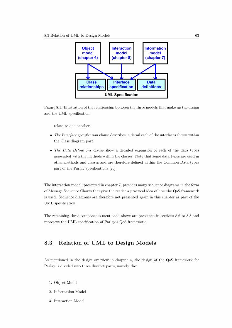
8.3 Relation of UML to Design Models 63
Figure 8.1: Illustration of the relationship between the three models that make up the design
and the UML specification.
relate to one another.
• The Interface specification clause describes in detail each of the interfaces shown within
the Class diagram part.
• The Data Definitions clause show a detailed expansion of each of the data types
associated with the methods within the classes. Note that some data types are used in
other methods and classes and are therefore defined within the Common Data types
part of the Parlay specifications [26].
The interaction model, presented in chapter 7, provides many sequence diagrams in the form
of Message Sequence Charts that give the reader a practical idea of how the QoS framework
is used. Sequence diagrams are therefore not presented again in this chapter as part of the
UML specification.
The remaining three components mentioned above are presented in sections 8.6 to 8.8 and
represent the UML specification of Parlay’s QoS framework.
8.3 Relation of UML to Design Models
As mentioned in the design overview in chapter 4, the design of the QoS framework for
Parlay is divided into three distinct parts, namely the:
1. Object Model
2. Information Model
3. Interaction Model
8.4 Parlay’s UML Methodologies 64
The relationships between these three design components and the various parts of the UML
specification presented in this chapter are illustrated in figure 8.1. The object model is used
to define the entities or classes that make up the QoS framework and certain relationships
between the classes. These classes are used as the framework for the interface specification.
The methods of each interface in the interface specification are defined by analysing the
Message Sequence Charts (MSCs) in the interaction model. The parameters of each method
are defined using the specifications in the information model.
8.4 Parlay’s UML Methodologies
The QoS framework is intended to be an extension of the Parlay API and must therefore
follow Parlay’s UML methodologies. Various applicable Parlay UML methodologies are
presented in the following sub-sections, and are followed by the UML specification of the
QoS framework in section 8.5.
8.4.1 Tools and Languages
The Unified Modelling Language (UML) [10] is used as the means to specify class diagrams
in the Parlay API.
8.4.2 Colours
For clarity, class diagrams follow a certain colour scheme: blue for application interface
packages and yellow for all the others.
8.4.3 Naming Scheme
The three primary Parlay API naming scheme conventions used in this report are sum-
marised in table 8.1. A complete description of the Parlay API naming scheme convention
is presented in [4]. Note that spaces within names are not allowed.
8.4.4 Exception Handling and Passing Results
Parlay methods communicate errors in the form of exceptions. Parlay methods themselves
generally use the return parameter to pass results. If no results are to be returned a void is
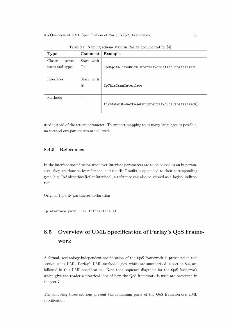
8.5 Overview of UML Specification of Parlay’s QoS Framework 65
Table 8.1: Naming scheme used in Parlay documentation [4].
Type Comment Example
Classes, struc-
tures and types
Start with
Tp TpCapitalizedWithInternalWordsAlsoCapitalized
Interfaces Start with
Ip IpThisIsAnInterface
Methods —
firstWordLowerCaseButInternalWordsCapitalized()
used instead of the return parameter. To support mapping to as many languages as possible,
no method out parameters are allowed.
8.4.5 References
In the interface specification whenever Interface parameters are to be passed as an in param-
eter, they are done so by reference, and the ‘Ref’ suffix is appended to their corresponding
type (e.g. IpAnInterfaceRef anInterface), a reference can also be viewed as a logical indirec-
tion.
Original type IN parameter declaration
IpInterface parm : IN IpInterfaceRef
8.5 Overview of UML Specification of Parlay’s QoS Frame-
work
A formal, technology-independent specification of the QoS framework is presented in this
section using UML. Parlay’s UML methodologies, which are summarised in section 8.4, are
followed in this UML specification. Note that sequence diagrams for the QoS framework
which give the reader a practical idea of how the QoS framework is used are presented in
chapter 7.
The following three sections present the remaining parts of the QoS frameworks’s UML
specification.
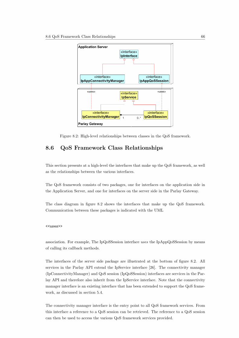
8.6 QoS Framework Class Relationships 66
Figure 8.2: High-level relationships between classes in the QoS framework.
8.6 QoS Framework Class Relationships
This section presents at a high-level the interfaces that make up the QoS framework, as well
as the relationships between the various interfaces.
The QoS framework consists of two packages, one for interfaces on the application side in
the Application Server, and one for interfaces on the server side in the Parlay Gateway.
The class diagram in figure 8.2 shows the interfaces that make up the QoS framework.
Communication between these packages is indicated with the UML
<<uses>>
association. For example, The IpQoSSession interface uses the IpAppQoSSession by means
of calling its callback methods.
The interfaces of the server side package are illustrated at the bottom of figure 8.2. All
services in the Parlay API extend the IpService interface [26]. The connectivity manager
(IpConnectivityManager) and QoS session (IpQoSSession) interfaces are services in the Par-
lay API and therefore also inherit from the IpService interface. Note that the connectivity
manager interface is an existing interface that has been extended to support the QoS frame-
work, as discussed in section 5.4.
The connectivity manager interface is the entry point to all QoS framework services. From
this interface a reference to a QoS session can be retrieved. The reference to a QoS session
can then be used to access the various QoS framework services provided.
8.7 QoS Framework Interface Classes 67
Figure 8.3: The extensions to the IpConnectivityManager interface.
The interfaces of the application side package are illustrated at the top of figure 8.2. All
callback interfaces in the Parlay API inherit from the IpInterface interface [26]. The connec-
tivity manager callback interface (IpAppConnectivityManager) and the QoS session callback
interface (IpAppQoSSession) therefore extend the IpInterface interface. These callback in-
terfaces are used by their corresponding server side services for communications (reports,
results, and errors) with the application side.
Each interface is examined in more detail in the following section.
8.7 QoS Framework Interface Classes
This section describes in more detail each interface described in the previous section. The
interfaces, methods and parameters of the QoS framework API are specified using UML. The
interface specification format defined in section 7 of [3] is followed. Note that the IpService
and IpInterface interfaces are defined in [3] and are therefore not repeated in this section.
The definition of method parameters are presented in section 8.8.
8.7.1 Interface IpConnectivityManager
The connectivity manager interface has been extended to support the QoS framework. Only
the extensions to the connectivity manager relating to the QoS framework and not the com-
plete specification are presented in this section. The existing specification of the connectivity
manager can however be found in [3].
The connectivity manager interface, illustrated in figure 8.3, is the entry point to the QoS
framework. After an application is authenticated and authorised by the Parlay Framework
[38], the client application discovers the Connectivity Manager interface, then the operator
can use this interface to step through the process of using the QoS framework.
Only one method is added to this interface: createQoSSession(). This method is used by
applications to get a reference to a new QoS session object.
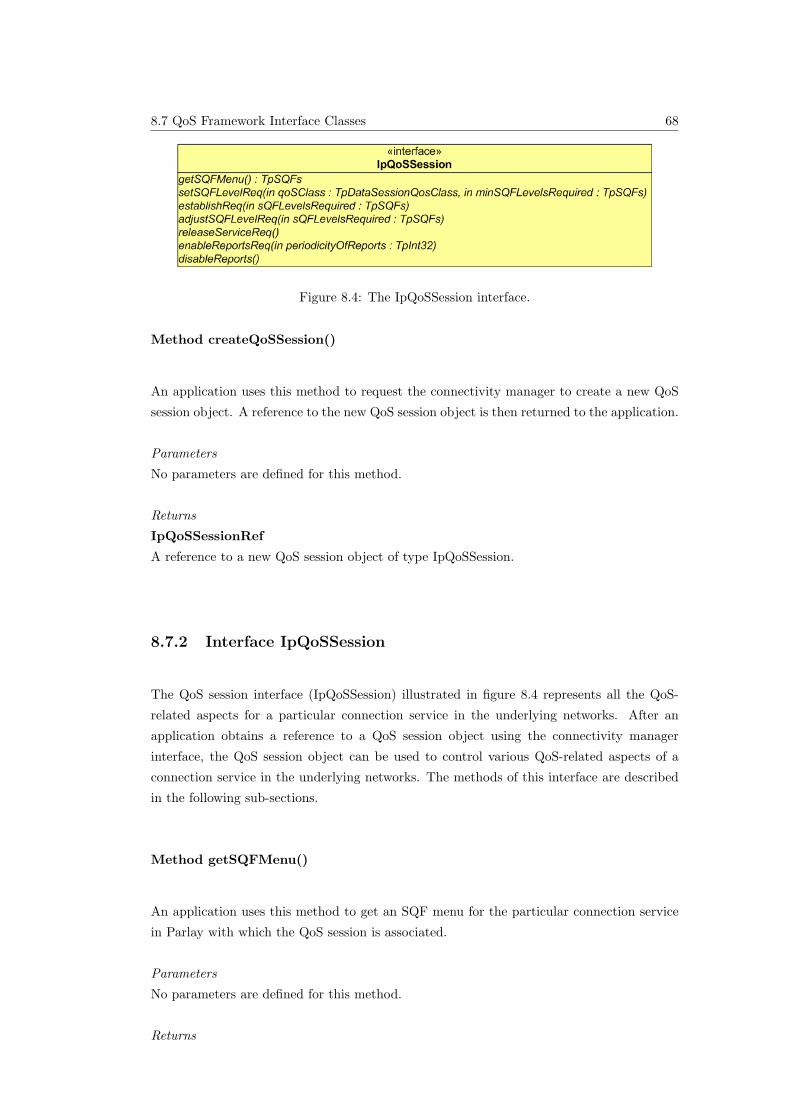
8.7 QoS Framework Interface Classes 68
Figure 8.4: The IpQoSSession interface.
Method createQoSSession()
An application uses this method to request the connectivity manager to create a new QoS
session object. A reference to the new QoS session object is then returned to the application.
Parameters
No parameters are defined for this method.
Returns
IpQoSSessionRef
A reference to a new QoS session object of type IpQoSSession.
8.7.2 Interface IpQoSSession
The QoS session interface (IpQoSSession) illustrated in figure 8.4 represents all the QoS-
related aspects for a particular connection service in the underlying networks. After an
application obtains a reference to a QoS session object using the connectivity manager
interface, the QoS session object can be used to control various QoS-related aspects of a
connection service in the underlying networks. The methods of this interface are described
in the following sub-sections.
Method getSQFMenu()
An application uses this method to get an SQF menu for the particular connection service
in Parlay with which the QoS session is associated.
Parameters
No parameters are defined for this method.
Returns
8.7 QoS Framework Interface Classes 69
TpSQFs
An SQF menu for the connection service with which the QoS session is associated describing
which SQFs are supported.
Method setSQFLevelReq()
An application uses this method to initially request SQF levels for a connection service.
Parameters
qoSClass
Describes the traffic class of the connection service.
minSQFLevelsRequired
The minimum SQF levels required by the application for the connection service.
Returns
Void.
Method establishReq()
An application uses this method to establish SQF levels for a connection service after re-
ceiving receiving a positive response from the setSQFLevelReq() call (setSQFLevelRes).
Parameters
sQFLevelsRequired
The SQF levels requested by the application for the connection service.
Returns
Void.
Method adjustSQFLevelReq()
An application uses this method to adjust SQF levels for a connection service after SQF
levels are already established using the establishReq() method.
Parameters
sQFLevelsRequired
The new SQF levels requested by the application for the connection service.
8.7 QoS Framework Interface Classes 70
Returns
Void.
Method releaseServiceReq()
An application uses this method to release QoS services for the connection with which it is
associated.
Parameters
No parameters are defined for this method.
Returns
Void.
Method enableReportsReq()
An application uses this method to enable reports from the underlying networks regarding
the achieved QoS levels for a connection service.
Parameters
periodicityOfReports
The frequency with which reports are generated in the network in seconds.
Returns
Void.
Method disableReports()
An application uses this method to disable reports from the underlying networks regarding
the QoS levels for a connection service.
Parameters
No parameters are defined for this method.
Returns
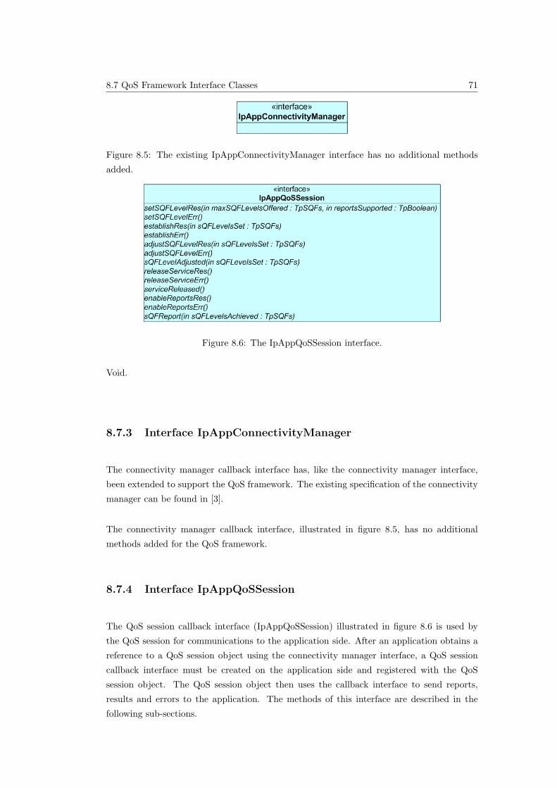
8.7 QoS Framework Interface Classes 71
Figure 8.5: The existing IpAppConnectivityManager interface has no additional methods
added.
Figure 8.6: The IpAppQoSSession interface.
Void.
8.7.3 Interface IpAppConnectivityManager
The connectivity manager callback interface has, like the connectivity manager interface,
been extended to support the QoS framework. The existing specification of the connectivity
manager can be found in [3].
The connectivity manager callback interface, illustrated in figure 8.5, has no additional
methods added for the QoS framework.
8.7.4 Interface IpAppQoSSession
The QoS session callback interface (IpAppQoSSession) illustrated in figure 8.6 is used by
the QoS session for communications to the application side. After an application obtains a
reference to a QoS session object using the connectivity manager interface, a QoS session
callback interface must be created on the application side and registered with the QoS
session object. The QoS session object then uses the callback interface to send reports,
results and errors to the application. The methods of this interface are described in the
following sub-sections.
8.7 QoS Framework Interface Classes 72
Method setSQFLevelRes()
A QoS session object uses this method to respond to the asynchronous setSQFLevelReq()
method call. It indicates that QoS is supported by the underlying networks and the maxi-
mum SQF levels that can be provided.
Parameters
maxSQFLevelsOffered
The maximum SQF levels offered by the underlying networks.
Parameters
reportsSupported
A boolean variable indicating whether reports are supported in the underlying networks.
Returns
Void.
Method setSQFLevelErr()
A QoS session object uses this method to respond to the asynchronous setSQFLevelReq()
method call. It indicates that an error occurred during the asynchronous task.
Parameters
No parameters are defined for this method.
Returns
Void.
Method establishRes()
A QoS session object uses this method to respond to the asynchronous establishReq()
method call. It indicates that the asynchronous request was successful.
Parameters
sQFLevelsSet
The SQF levels actually set for the connection service in the underlying networks.
Returns
Void.
8.7 QoS Framework Interface Classes 73
Method establishErr()
A QoS session object uses this method to respond to the asynchronous establishReq()
method call. It indicates that an error occurred during the asynchronous task.
Parameters
No parameters are defined for this method.
Returns
Void.
Method adjustSQFLevelRes()
A QoS session object uses this method to respond to the asynchronous adjustSQFLevelReq()
method call. It indicates that the asynchronous request was successful.
Parameters
sQFLevelsSet
The new SQF levels actually set for the connection service in the underlying networks.
Returns
Void.
Method adjustSQFLevelErr()
A QoS session object uses this method to respond to the asynchronous adjustSQFLevelReq()
method call. It indicates that an error occurred during the asynchronous task.
Parameters
No parameters are defined for this method.
Returns
Void.
8.7 QoS Framework Interface Classes 74
Method sQFLevelAdjusted()
A QoS session object uses this method to indicate to the application that SQF levels were
adjusted by the underlying networks (without the application requesting an adjustment).
Parameters
sQFLevelsSet
The SQF levels actually set for the connection service in the underlying networks.
Returns
Void.
Method releaseServiceRes()
A QoS session object uses this method to respond to the asynchronous releaseServiceReq()
method call. It indicates that the asynchronous request was successful.
Parameters
No parameters are defined for this method.
Returns
Void.
Method releaseServiceErr()
A QoS session object uses this method to respond to the asynchronous releaseServiceReq()
method call. It indicates that an error occurred during the asynchronous task.
Parameters
No parameters are defined for this method.
Returns
Void.
8.7 QoS Framework Interface Classes 75
Method serviceReleased()
A QoS session object uses this method to indicate that the connection service has been
released without the application requesting release of the service.
Parameters
No parameters are defined for this method.
Returns
Void.
Method enableReportsRes()
A QoS session object uses this method to respond to the asynchronous enableReportsReq()
method call. It indicates that the asynchronous request was successful.
Parameters
No parameters are defined for this method.
Returns
Void.
Method enableReportsErr()
A QoS session object uses this method to respond to the asynchronous enableReportsReq()
method call. It indicates that an error occurred during the asynchronous task.
Parameters
No parameters are defined for this method.
Returns
Void.
8.8 QoS Framework Data Definitions 76
Method sQFReport()
A QoS session object uses this method to report the achieved SQF levels for a connection
service in the underlying networks.
Parameters
sQFLevelsAchieved
The measures SQF levels for the connection service in the underlying networks.
Returns
Void.
8.8 QoS Framework Data Definitions
The data type definitions for the QoS framework are presented in this section. These data
types are used in the methods of the various interfaces of the QoS framework presented in
the interface specification in section 8.7.
Note that the data type definitions for the following data types are defined in the Parlay
specifications [26], and are therefore not repeated in this section.
• TpSessionID
• TpInt32
• TpDataSessionQoSClass – discussed in section 3.4.2
• TpBoolean
Only two additional data types are specified in the QoS framework, namely:
• TpSQF: which represents a single Service Quality Feature (SQF); and
• TpSQFs: which represents a group of SQFs composed of type TpSQF.
These data types are summarised in the following sub-sections.
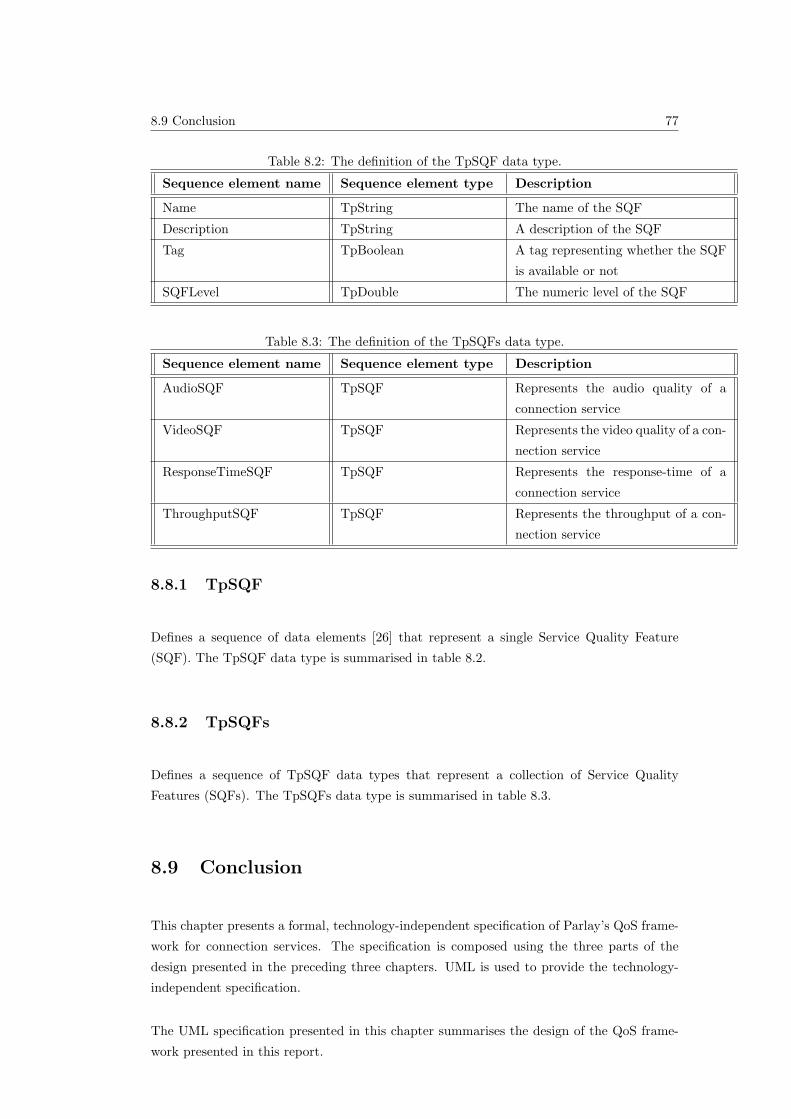
8.9 Conclusion 77
Table 8.2: The definition of the TpSQF data type.
Sequence element name Sequence element type Description
Name TpString The name of the SQF
Description TpString A description of the SQF
Tag TpBoolean A tag representing whether the SQF
is available or not
SQFLevel TpDouble The numeric level of the SQF
Table 8.3: The definition of the TpSQFs data type.
Sequence element name Sequence element type Description
AudioSQF TpSQF Represents the audio quality of a
connection service
VideoSQF TpSQF Represents the video quality of a con-
nection service
ResponseTimeSQF TpSQF Represents the response-time of a
connection service
ThroughputSQF TpSQF Represents the throughput of a con-
nection service
8.8.1 TpSQF
Defines a sequence of data elements [26] that represent a single Service Quality Feature
(SQF). The TpSQF data type is summarised in table 8.2.
8.8.2 TpSQFs
Defines a sequence of TpSQF data types that represent a collection of Service Quality
Features (SQFs). The TpSQFs data type is summarised in table 8.3.
8.9 Conclusion
This chapter presents a formal, technology-independent specification of Parlay’s QoS frame-
work for connection services. The specification is composed using the three parts of the
design presented in the preceding three chapters. UML is used to provide the technology-
independent specification.
The UML specification presented in this chapter summarises the design of the QoS frame-
work presented in this report.

8.9 Conclusion 78
One aspect not addressed in this UML specification is the inclusion of exceptions [39] thrown
by an object providing a service. This must be addressed in future work to render the UML
specification complete.
The following chapter (9) presents a technology-dependent simulation of the design and
UML specification to prove their validity.
9.2 Objectives of Simulation 79
Chapter 9
Software Simulation of QoS
Framework
9.1 Introduction
This chapter presents the proof of concept or simulation of the design of Parlay’s QoS
framework presented in this report.
The simulation is a multi-threaded [12], distributed CORBA [13] application implemented
in JAVA [14] (Java SDK version 1.5).
The objectives of the simulation are summarised in the following section (9.2). Section
9.3 presents the design of the simulation, followed by the implementation details of the
simulation in section 9.4.
9.2 Objectives of Simulation
The primary goals of the simulation presented in this chapter are to prove that the design
of the QoS framework and its UML specification presented in this report are:
• Complete: the interfaces, methods and parameters defined in the UML specification
are sufficient for all required interactions;
• Realistic: It is possible to implement the QoS framework;
• Compatible: The UML specification is compatible with standard Parlay implementa-
tion technologies like JAVA and CORBA; and
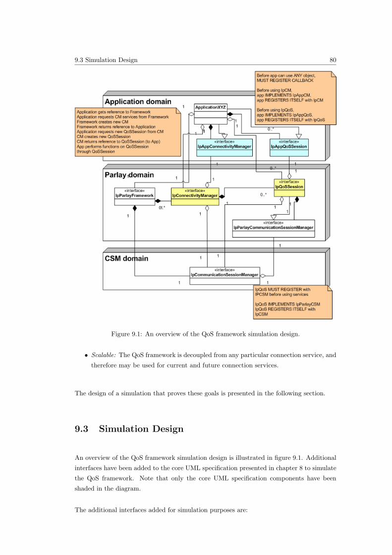
9.3 Simulation Design 80
Figure 9.1: An overview of the QoS framework simulation design.
• Scalable: The QoS framework is decoupled from any particular connection service, and
therefore may be used for current and future connection services.
The design of a simulation that proves these goals is presented in the following section.
9.3 Simulation Design
An overview of the QoS framework simulation design is illustrated in figure 9.1. Additional
interfaces have been added to the core UML specification presented in chapter 8 to simulate
the QoS framework. Note that only the core UML specification components have been
shaded in the diagram.
The additional interfaces added for simulation purposes are:
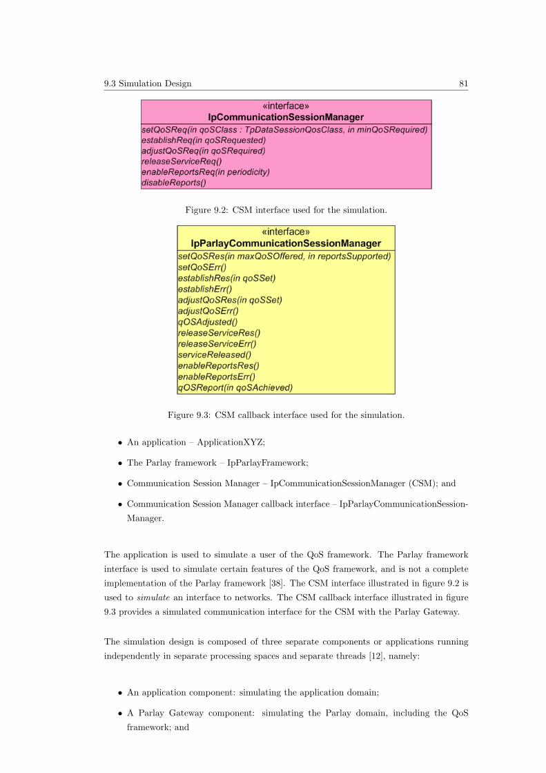
9.3 Simulation Design 81
Figure 9.2: CSM interface used for the simulation.
Figure 9.3: CSM callback interface used for the simulation.
• An application – ApplicationXYZ;
• The Parlay framework – IpParlayFramework;
• Communication Session Manager – IpCommunicationSessionManager (CSM); and
• Communication Session Manager callback interface – IpParlayCommunicationSession-
Manager.
The application is used to simulate a user of the QoS framework. The Parlay framework
interface is used to simulate certain features of the QoS framework, and is not a complete
implementation of the Parlay framework [38]. The CSM interface illustrated in figure 9.2 is
used to simulate an interface to networks. The CSM callback interface illustrated in figure
9.3 provides a simulated communication interface for the CSM with the Parlay Gateway.
The simulation design is composed of three separate components or applications running
independently in separate processing spaces and separate threads [12], namely:
• An application component: simulating the application domain;
• A Parlay Gateway component: simulating the Parlay domain, including the QoS
framework; and
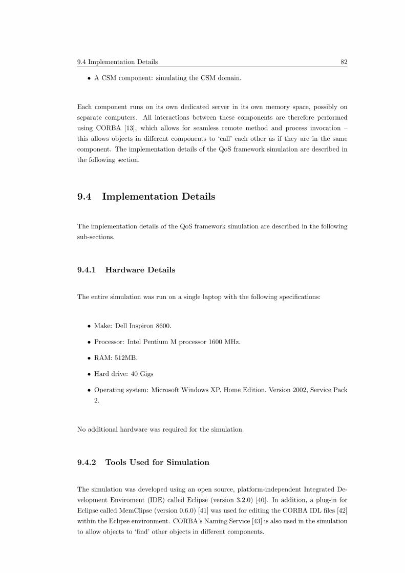
9.4 Implementation Details 82
• A CSM component: simulating the CSM domain.
Each component runs on its own dedicated server in its own memory space, possibly on
separate computers. All interactions between these components are therefore performed
using CORBA [13], which allows for seamless remote method and process invocation –
this allows objects in different components to ‘call’ each other as if they are in the same
component. The implementation details of the QoS framework simulation are described in
the following section.
9.4 Implementation Details
The implementation details of the QoS framework simulation are described in the following
sub-sections.
9.4.1 Hardware Details
The entire simulation was run on a single laptop with the following specifications:
• Make: Dell Inspiron 8600.
• Processor: Intel Pentium M processor 1600 MHz.
• RAM: 512MB.
• Hard drive: 40 Gigs
• Operating system: Microsoft Windows XP, Home Edition, Version 2002, Service Pack
2.
No additional hardware was required for the simulation.
9.4.2 Tools Used for Simulation
The simulation was developed using an open source, platform-independent Integrated De-
velopment Enviroment (IDE) called Eclipse (version 3.2.0) [40]. In addition, a plug-in for
Eclipse called MemClipse (version 0.6.0) [41] was used for editing the CORBA IDL files [42]
within the Eclipse environment. CORBA’s Naming Service [43] is also used in the simulation
to allow objects to ‘find’ other objects in different components.
9.4 Implementation Details 83
9.4.3 Setting Up the Environment
The prerequisites for compiling and running the simulation are:
• A JAVA compiler: to compile the source code;
• A CORBA module: to allow remote method invocation;
• An IDL-to-JAVA compiler: to generate JAVA stubs from IDL files; and
• A CORBA naming service: to allow objects to ‘find’ other CORBA objects.
All these modules are bundled with the JAVA SDK 1.5. To install the JAVA SDK, simply
copy the downloaded folder to any location on the computer, and then set the PATH envi-
ronment variable to the location of the bin folder, which is located in the first level of the
downloaded folder.
9.4.4 Compilation Details
All interfaces that must be accessed remotely, from a different component or application,
must be defined as CORBA objects. To define an object as a CORBA object, an IDL file
must be written to specify the interface in a language-independent way. An IDL-to-JAVA
compiler is then run on the IDL file, the result of which is a JAVA stub for the interface.
This JAVA stub can then be used by a client application to access the object remotely.
All the QoS framework IDL definitions may be found together with the source code in [15].
9.4.5 Running the Simulation
Once the environment is configured as described in section 9.4.3, the simulation of the QoS
framework can be run. All source code for the simulation may be found in [15]. The
instructions for running the simulation presented in this section may be found with the
source code in the
README.txt
file.
Each server uses CORBA’s naming service to get initial references to remote objects, which
means that before the servers are started, the Naming Service must be started.
9.5 Conclusion 84
To start the naming service and run the various parts of the application, a set of batch files
which contain the required commands must be double-clicked in the Windows environment.
The order in which the batch files are clicked are however very important. The batch files
are all located in the same location:
ParlayQoSFrameworkSimulation\ALL-SOURCE\
As can be seen, there are 6 batch files in this folder, all of which are pre-pended with numbers
0 to 5. The first two, 0 and 1, are used to generate JAVA source code from IDL files and to
compile the JAVA files. These two batch files do not need to be clicked since they are
already compiled.
To start the application, double click the remaining batch files in numerical order:
1. 2-StartNamingService.bat
2. 3-StartCSMServer.bat
3. 4-StartParlayServer.bat
4. 5-StartApplicationServer.bat
A different console window pops up for each of these services (to force a window closed, press
CTRL-C). The application presents a menu, which can be followed to test the operation of
the QoS framework.
9.5 Conclusion
This chapter presents the proof of concept or simulation of the design of Parlay’s QoS
framework presented in this report to validate it. The simulation is a multi-threaded, dis-
tributed CORBA application implemented in JAVA (Java SDK version 1.5) and is based
on the UML specification of the QoS framework described in chapter 8. Details about the
simulation design and implementation are also summarised in this chapter.
The simulation presented in this chapter validates that the design of the QoS framework
presented in this report is complete, realistic, Parlay-compatible and scalable, as defined in
section 9.2.
10.2 Conclusions 85
Chapter 10
Conclusion
10.1 Summary
This report presents the design, specification and simulation of a QoS framework for con-
nection services in Parlay. The QoS framework enables applications to specify QoS levels
for connection services like call and data session control services in Parlay.
The design is divided into 3 parts: the object model (which defines the objects that make
up the QoS framework), the information model (which deals with QoS specification and
associated mapping), and the interaction model (which defines user interaction mechanisms).
The design of each component is presented.
A formal, technology-independent specification of Parlay’s QoS framework for connection
services is presented. The specification is composed using the three parts of the design.
UML is used to provide the technology-independent specification.
A proof of concept of the design of Parlay’s QoS framework presented in this report is
also described to validate the framework. The simulation is a multi-threaded, distributed
CORBA application implemented in JAVA (Java SDK version 1.5) and is based on the UML
specification of the QoS framework described in chapter 8. Details about the simulation
design and implementation are also summarised.
10.2 Conclusions
The QoS framework presented in this report:
10.3 Future Work 86
• Supports existing and future connection services in Parlay;
• Provides per-application, per-connection QoS support to applications;
• Follows Parlay’s existing design paradigms; and
• Co-exists with and make use of existing and future Parlay infrastructure.
The simulation presented in the previous chapter also validates that the design of the QoS
framework is:
• Complete: the interfaces, methods and parameters defined in the UML specification
are sufficient for all required interactions;
• Realistic: It is possible to implement the QoS framework;
• Compatible: The UML specification is compatible with standard Parlay implementa-
tion technologies like JAVA and CORBA; and
• Scalable: The QoS framework is decoupled from any particular connection service, and
therefore may be used for current and future connection services.
Parlay guidelines relating to permitted changes to the Parlay API are followed strictly in
the design of the QoS framework, which ensures the backward compatibility of Parlay if the
QoS framework is added to the Parlay API. All Parlay design guidelines are also followed
to allow for the easy integration of the QoS framework into the Parlay API.
10.3 Future Work
The mapping of SQFs to the generic QoS parameters in the information model is not unique,
since the level of the SQFs are not completely objective. The mapping to each GQoS
parameter from the same SQF level could potentially be different for each implementation
of the information model. This mapping process is complex and outside the scope of this
report, but must be further investigated in future work.
The use of the existing generic QoS parameters defined in the Connectivity Manager SCF
avoids redundancy in the information model, building on existing design concepts in the
Parlay API. The feasibility of these parameters must however be verified. In particular,
future work involves verifying whether these parameters are complete and applicable, as
discussed in section [11].
One aspect not addressed in the QoS framework UML specification is the inclusion of ex-
ceptions thrown by an object providing a service. This must be addressed in future work to
render the UML specification complete.

10.3 Future Work 87
The performance of the QoS framework design has not at the time of writing been analysed
in terms of factors like memory efficiency and processing speed. A particular performance
issue might be the use of a new object for every session in the object model. If performance is
found to be unsatisfactory in an implementation of the QoS framework, this design approach
might have to be altered to improve system performance.
An effort must be made to integrate the QoS framework into the core Parlay API, to allow
applications to access the various QoS services.
REFERENCES 88
References
[1] NORTEL, “Introduction to Quality of Service (QoS),” Nortel Networks, Tech. Rep.,
2003.
[2] ETSI, “ETSI TS 123 107,” 3GPP, Technical specification v6.3.0, June 2005, UMTS
Quality of Service (QoS) concept and architecture.
[3] ——, “ETSI ES 203 915-10,” The Parlay Group, OSA API Standards document v1.1.1,
April 2005, Part 10: Connectivity Manager Service Capability Feature.
[4] ——, “ETSI ES 203 915-1,” The Parlay Group, OSA API Standards document v1.1.1,
April 2005, Part 1: Overview.
[5] TINA-C, “Network Resource Architecture,” TINA, Tech. Rep. Version 3, February
1997.
[6] J. Gozdecki, A. Jajszczyk, and R. Stankiewicz, “Quality of Service Terminology in IP
Networks,” IEEE Communications Magazine, pp. 153 – 159, March 2003.
[7] J. K. Andersson, C. Nyberg, and M. Kihl, “Performance analysis and overload control
of an open service access (OSA) architecture,” Department of Communication Systems,
Lund Institute of Technology, Tech. Rep., 2003.
[8] P. Moodley and H. Hanrahan, “Design of a Parlay Network Application Programming
Interface and Associated Architecture,” Submitted to SATNAC 2006, Tech. Rep., 2006.
[9] A. Yew, C. Bohoris, A. Liotta, and G. Pavlou, “Quality of Service Management for
the Virtual Home Environment (VHE),” Centre for Communication Systems Research,
School of Electronics, Computing & Mathematics, University of Surrey, Guildford, Sur-
rey., Tech. Rep., 2001.
[10] Wikipedia contributors, “Unified Modeling Language,” Wikipedia, The Free
Encyclopedia, August 2006. [Online]. Available: http://en.wikipedia.org/wiki/
Unified Modeling Language
[11] ETSI, “ETSI ES 203 915-4-2,” The Parlay Group, OSA API Standards document
v1.1.1, April 2005, Part 4: Call Control; Sub-part 2: Generic Call Control SCF.
[12] Wikipedia contributors, “Thread (computer science),” Wikipedia, The Free
Encyclopedia, July 2006. [Online]. Available: http://en.wikipedia.org/wiki/Thread %
28computer science%29
REFERENCES 89
[13] ——, “Common Object Request Broker Architecture (CORBA),” Wikipedia, The Free
Encyclopedia, August 2006. [Online]. Available: http://en.wikipedia.org/wiki/Corba
[14] ——, “Java programming language,” Wikipedia, The Free Encyclopedia, August 2006.
[Online]. Available: http://en.wikipedia.org/w/index.php?title=Java programming
language&oldid=72644306
[15] Y. Bata, “QoS framework simulation code and documentation.” [Online]. Available:
http://dept.ee.wits.ac.za/∼bata/ParlayQoSFrameworkSimulation.zip
[16] ——, “QoS framework online documentation.” [Online]. Available: http://dept.ee.
wits.ac.za/∼bata/ParlayQoSFrameworkSimulation/doc/index.html
[17] C. Aurrecoechea, A. T. Campbell, and L. Hauw, “A survey of QoS architectures,”
Multimedia Systems, vol. 6, pp. 138–151, 1998.
[18] Z. Cekro, “Quality of Service - Overview of Concepts and Standards,” COST 256, April
1999, university of Brussels, VUB.
[19] A. van Halteren, L. Franken, D. de Vries, I. Widya, G. Tquerres, J. Pouwelse, and
P. Copeland, “Deliverable 3.1.1: QoS architectures and mechanisms - State-of-the-art,”
AMIDST, Tech. Rep. AMIDST/WP3/N005/V09, January 1999.
[20] I. Grgic and C. Hatch, “P1103 - Inter-Operator IP QoS Framework - ToIP and UMTS
Case Studies,” Eurescom, Tech. Rep., June 2001.
[21] C. Aurrecoechea, A. T. Campbell, and L. Hauw, “A Survey of QoS Architectures,”
IEEE, 1998, Center for Telecommunication Research, Columbia University, New York.
[22] U. Jutila, M. Koponen, M. Ranta-aho, P. H. Holder, D. Ubhi, C. Brou, J. Aronsheim-
Grotsch, J. Hall, M. Smirnow, M. Tschichholz, R. Roth, A. Gravey, G. Kovcs,
L. Franken, R. Ligtmans, O. Espvik, I. Grgic, T. Jensen, J.-E. Kosberg, L. S. Cardoso,
P. Arede, F. M. F. Fonseca, R. Roque, J. Rodrigues, B. Rutersten, and H. Sammelin, “A
Common Framework for QoS/Network Performance in a multi-Provider Environment,”
EURESCOM, Tech. Rep., September 1999.
[23] J.-P. Richter and H. de Meer, “Towards Formal Semantics for QoS Support,” IEEE,
pp. 472–479, 1998, University of Hamburg, Computer Science Department, Telecom-
munications and Computer Networks Division.
[24] C. Becker and K. Geihs, “Generic QoS-Support for CORBA,” IEEE, vol. 0-7695-0722,
pp. 60–65, 2000, computer Science Department, University of Frankfurt.
[25] F. Bennani and N. Simoni, “Dynamic Management for End-to-end IP QoS: from Re-
quirements to Offers,” IEEE, vol. 0-7695-072, pp. 353–358, 2000.
[26] ETSI, “ETSI ES 203 915-2,” The Parlay Group, OSA API Standards document v1.1.1,
April 2005, Part 2: Common Data Definitions.
[27] F. Siqueira and V. Cahill, “Quartz: A QoS Architecture for Open Systems,” Master’s
thesis, Distributed Systems Group, Department of Computer Science, Trinity College
REFERENCES 90
Dublin, Ireland, distributed Systems Group, Department of Computer Science, Trinity
College Dublin, Ireland.
[28] The TINA Consortium, “TINA-C.” [Online]. Available: http://www.tinac.com/
[29] T. Hamada, S. Hogg, J. Rajahalme, C. Licciardi, L. Kristiansen, and P. F. Hansen,
“Service Quality in TINA: Quality of Service Trading in Open Network Architecture,”
IEEE Communications Magazine, vol. 0163-6804, pp. 122 – 130, August 1998.
[30] A. van Halteren, “A concept space for modelling QoS aspects,” January 2002, KPN
Presentation.
[31] S. Fischer, M. Vall, O. M. Salem, and G. von Bochmann, “Application Design for
Cooperative QoS Management,” University of Montreal, Departement IRO, Tech. Rep.,
2000.
[32] Wikipedia contributors, “Sequence diagram,” Wikipedia, The Free Encyclopedia, July
2006. [Online]. Available: http://en.wikipedia.org/wiki/Sequence diagram
[33] ——, “Specification and Design Language (SDL),” Wikipedia, The Free Encyclopedia,
August 2006. [Online]. Available: http://en.wikipedia.org/wiki/Specification and
Description Language
[34] ——, “Design pattern (computer science),” Wikipedia, The Free Encyclopedia,
August 2006. [Online]. Available: http://en.wikipedia.org/wiki/Design pattern %
28computer science%29
[35] ——, “Factory method pattern,” Wikipedia, The Free Encyclopedia, August 2006.
[Online]. Available: http://en.wikipedia.org/wiki/Factory design pattern
[36] J. Yan, “Service Demonstration: VPN Provisioning Using the OSA / Parlay Connection
Management Interface,” Master’s thesis, WITS University, April 2006.
[37] Parlay, “The No-Nonsense Guide to Parlay/OSA,” January 2005.
[38] ETSI, “ETSI ES 201 915-3,” The Parlay Group, OSA API Standards document v1.5.1,
April 2005, Part 3: Framework.
[39] Wikipedia contributors, “Exception handling,” Wikipedia, The Free Encyclopedia,
September 2006. [Online]. Available: http://en.wikipedia.org/wiki/Exceptions
[40] Eclipse Foundation Inc., “Eclipse.org home.” [Online]. Available: http://www.eclipse.
org/
[41] M. Berner, “MemClipse 0.6.0,” February 2006. [Online]. Available: http:
//www.mem2b.org/
[42] Object Management Group (OMG), “OMG IDL: Details,” August 2006. [Online].
Available: http://www.omg.org/gettingstarted/omg idl.htm
[43] BEA Systems, Inc., “Overview of the CORBA Name Service,” August 2006. [Online].
Available: http://edocs.bea.com/wle/naming/over.htm