a qos framework to support integrated services in multihop wireless networks with infrastructure...
TRANSCRIPT

Computer Communications 31 (2008) 3253–3266
Contents lists available at ScienceDirect
Computer Communications
journal homepage: www.elsevier .com/locate /comcom
A QoS framework to support integrated services in multihop wireless networkswith infrastructure support
Huiqing Wang *, Kin Choong YowSchool of Computer Engineering, Nanyang Technological University, N4-B2c-06, Nanyang Avenue, Singapore 639798, Singapore
a r t i c l e i n f o a b s t r a c t
Article history:Received 24 February 2007Received in revised form 19 May 2008Accepted 19 May 2008Available online 5 June 2008
Keywords:QoSFairnessLoad-balanceEnd-to-end
0140-3664/$ - see front matter � 2008 Elsevier B.V. Adoi:10.1016/j.comcom.2008.05.023
* Corresponding author. Tel.: +65 9863 1468.E-mail addresses: [email protected], h
Wang), [email protected] (K.C. Yow).
In this paper, we consider a multihop wireless network with infrastructure support (MWNI) which can bebuilt upon existing IEEE 802.11 based WLANs to extend the coverage and provide more flexibility toadapt to the dynamics of the network. To support integrated services in MWNI, a QoS framework is pro-posed to achieve the following objectives: (1) allow more real-time flows to be admitted into the net-work, (2) optimize the performance of best-effort traffic without losing fairness and (3) enhance QoSperformance of admitted real-time traffic. There are three main components in our framework to providecorresponding solutions. First, a new QoS routing protocol that discovers global optimized topology basedon the network interference modeled by flow contention graph. Second, admission control is performedat the access point (AP) so that a flow will be admitted only if the network has enough bandwidth to sup-port its minimum bandwidth requirement. Third, a two-level hierarchical scheduling algorithm based onweighted fair queueing is implemented at the APs. The efficiency of individual component, as well as theQoS framework is evaluated through simulation studies, and the results show our proposed QoS frame-work is able to enhance the QoS of real-time traffic and still achieve high network utilization.
� 2008 Elsevier B.V. All rights reserved.
1. Introduction
Wireless local area network (WLAN) is currently the majorchoice of wireless technologies for many applications due to itseasy administration using access point (AP) as a central entity, has-sle-free set-up (cable-free) and low cost. However, the bandwidththat can be supported in wireless networks is quite limited com-pared to its counterpart, the wired network. The advertised54 Mbp bandwidth for IEEE 802.11a/g is the peak rate that canbe achieved and it drops greatly as the communication range in-creases. In WLANs, only the mobile hosts (MHs) that are withinthe transmission range of the APs can establish a connection tothe backbone. This is likely to cause uneven load distributionamong multiple APs because some APs will be overloaded withtoo many users and the congestion incurred will greatly degradethe network performance. In this paper, we consider a multihopwireless network with infrastructure support (MWNI) which canbe implemented by extending current WLANs with multihoptransmission. In MWNIs, the network coverage can be extendedwith multihop wireless links, which enables the MHs to establishassociation with APs that are out of direct transmission range.
In MWNIs, single NIC with half-duplexing antenna is assumedto be equipped with each MH to keep our proposal compatible
ll rights reserved.
with most of the current wireless devices. The APs are assumedto connect to the network backbone which is connected to theInternet or Intranet. An example of MWNI is shown in Fig. 1. Mostuser traffic in such network is usually to/from the Internet or Intra-net backbone, load-balance can be achieved if the MH can chooseto associate with a less loaded AP. This will alleviate congestionand improve the network utilization. In IEEE 802.11 standards[1], multiple orthogonal frequency channels are defined (3 for IEEE802.11b/g and 12 for IEEE 802.11a). To reduce interference and tomaximize the usage of the channels, neighboring APs usually oper-ate at orthogonal channels. In MWNIs, the flexibility of networkorganization as in ad hoc networks can be achieved and at thesame time, the existence of infrastructure enables further perfor-mance optimization.
In this paper, a QoS framework consisting of various compo-nents is proposed to support integrated services (QFIS) in MWNIs.Traffic with various QoS requirements should be supported. First, aQoS routing algorithm based on a flow contention graph (FCGQR) isproposed to find a route with the highest additional end-to-endachievable share (AEAS) for the flows based on the contentionexperienced by its bottleneck link. Based on the bandwidth ofthe route discovered, admission control for real-time traffic is per-formed at the AP which will keep the contention in the networkbelow the level that is supported by the channel capacity. Consid-ering the coexistence of real-time traffic and best-effort traffic,scheduling policies should be defined to guarantee the QoS forreal-time traffic and to optimize the fairness among the best-effort

backbone
B
AP1 AP2
AC
D
EF
G
Fig. 1. Multihop wireless network with infrastructure support (MWNI).
3254 H. Wang, K.C. Yow / Computer Communications 31 (2008) 3253–3266
flows. However, complex scheduling algorithms are not suitablefor these resource-limited mobile devices because the overhead re-quired for information maintenance is too expensive for them. Inour work, a hierarchical scheduling algorithm based on weightedfair queueing is implemented at the AP which further optimizesthe performance for both real-time traffic and best-effort traffic.With the APs serving as the central scheduling point in each span-ning tree, they can be easily updated to support our algorithms.The MHs can also greatly improve the QoS with little overhead in-curred. Fig. 2 illustrates the whole framework.
The organization of the rest of this paper is as follows: Prelim-inaries and assumptions are first discussed in Section 2. In Section3, an optimized algorithm to estimate the bottleneck bandwidth inMWNIs is proposed. Our proposed QoS framework is then intro-duced in Sections 4–6, followed by the performance evaluation inSection 7. In Section 8, related work in the literature is introduced.Finally, Section 9 summarizes the paper.
2. Preliminaries and assumptions
2.1. Preliminaries
A multihop flow in MWNI can be deemed as several link levelflows where packets are transmitted from one end of the link to
QoS Routing Module
Admission Controller
Hierarchical Scheduler
QoS Frame work for MWNIs
T r a f f i c p r o f i l e
Admitted traffic
Traffic profile
Traffic profile
Fig. 2. QoS framework for MWNIs.
E
C D
B
A
F
F1
F2
F3
F4
F5
(a) Inter-flow interference
Fig. 3. Interference in multi
the other end of the link. To differentiate the link flows from themultihop flow which is from the source to the destination (end-to-end), we will use flow to exclusively denote the multihop flowand use subflow to denote the link flow in rest of our discussion.For example, a multihop flow F2 in Fig. 3(b) consists of 3 subflows,i.e. f2;1 from AP to B, f2;2 from B to C and f2;3 from C to D.
Here we adopt the interference model that is used in [2], wheretwo subflows are defined as contending subflows (or we say onesubflow contends with another subflow) if either end of one sub-flow falls within the transmission range of the nodes in eitherend of another subflow. If we say multiple subflows are contendingflows, we actually mean that each of these subflows is contendingwith all of the other subflows and they form a contention group. Bythis definition, for all the subflows in Fig. 3(b), every distinct pair ofthem are contending subflows and together they form a contentiongroup.
In this paper, a weight wi is used to characterize a flow Fi
which is proportional to its minimum bandwidth requirementbi, i.e. wi ¼ bi=r where r is the bandwidth that represents anavailable QoS level. We assume real-time traffic is sent in con-stant rate in this paper, variable bit rate (VBR) can be also sup-ported by using the average value. For best-effort traffic, they areusually transmitted with flow-controlled protocols like TCP toprovide reliable delivery. The slow-start and congestion avoid-ance mechanisms of such transmission protocol will make thesending traffic bursty and unpredictable. Since no QoS is guaran-teed for a best-effort flow, its weight is declared to zero. Sincethe performance of the flow such as delivery ratio, end-to-enddelay, etc., is measured end-to-end, we define the weight of asubflow to be the same weight of the multihop flow it belongsto.
2.2. Network model
The contention in the network can be modeled as an arbitraryundirected and weighted graph G ¼ ðV ; EÞ, where V is the vertexset of G and E � V � V is the edge set of G. In the subflow conten-tion graph Gfl, all the subflows constitute the vertex set and there isan edge between two subflows in the graph if they are contendingsubflows. Similarly, the flow contention graph GF can be definedbased on the contention relationship of flows. For the scenario inFig. 4, the corresponding subflow contention graph and flow con-tention graph are shown in Figs. 5(a) and (b).
A clique cl in a graph is a subset of V such that for any pair ofdistinct nodes u; v 2 cl, the edge ðu; vÞ 2 E always stands. Theweight of a clique is defined as the sum of the weight of all thenodes in the clique. The clique with the maximum weight in thegraph is called maximum clique bcl. Also we use CLðV 0Þ to refer tothe set of cliques for the set of nodes V 0 � V in the graph, or simplyCL if V 0 ¼ V .
AP D BC
AF1
F2
f2, 1 f2, 3
f1, 1
f2, 2
(b) Intra-flow interference
hop wireless networks.

F2 F1
F3 F4
f4, 1
f1, 2 f2, 1
f1, 1
f2, 2
f3, 1
f3, 3
f3, 2 f4, 2
f4, 3
AP
A
B
C
D
E
J
F
G
H
I
Fig. 4. Contending flows and subflows.
f4, 1 f4, 3
f3, 2
f4, 2
f3, 1 f3, 3
f2, 2
f1, 1
f2, 1
f1, 2
(a) Sub flow contention graph
F1 F2
F3 F4
(b) Flow contention graph
Fig. 5. Model traffic contention in MWNIs.
H. Wang, K.C. Yow / Computer Communications 31 (2008) 3253–3266 3255
We further define that a constraint cliquedscli for a flow Fi is a cli-que in the Gfl (we call this the subflow clique scl to differentiate itfrom the clique found in the flow contention graph GF which is de-noted as flow clique fcl) that contains any subflow fi;j 2 Fi (1 6 i 6 N,1 6 j 6 hi) and has the maximum weight.
2.3. Assumptions
The following assumptions are used for our discussion ofMWNIs in this paper:
� The network is assumed to be combinatorially stable [3], that is,the topology cannot change too fast that no transmission can befinished.
� In MWNIs, we assume that most of the traffic is downlink traffic,i.e. from the APs to the MHs. This assumption is valid for scenar-ios where the backbone traffic constitutes the majority of thetraffic in MWNIs.
� The nodes in MWNIs do not move frequently. Unlike MANETs,where the nodes may move frequently, such assumption usuallydoes not stand in MWNIs. Considering the specific traffic patternin MWNIs and possible applications in reality, like WLANs in lec-ture room, cafe, etc., users normally don’t move frequently whileoccasional leaving and joining are expected.
� The routes used by the multihop flows in MWNIs have no short-cut (we follow the name used in [4]). For the example in Fig. 6(the circle represents the effective transmission range of theMH), there is a shortcut for the multihop flow in Fig. 6(a) thatthe flow can take the shortcut by directly connecting from B toD instead of taking an extra hop through C. Such unnecessaryforwarding will waste network resources and increase theend-to-end delay. In Section 4, our routing algorithm guaranteesonly the route like that in Fig. 6(b) will be used.
� DCF MAC, which is proposed in IEEE 802.11 standard, isassumed to be used as the underlying MAC in our proposal. Inpacket-switched wired networks, only the backlogged flowsfor the same link will contend for the medium access. However,in wireless networks, all the packets are broadcast in the sharedmedium and two transmission in range may cause collision andpacket loss. With DCF MAC, a node will sense the medium andonly make transmission if the medium is idle.
3. Estimate the bottleneck bandwidth in MWNIs
In MWNIs, flows contend not only for the shared link, but also forthe shared medium which is topology-dependent. So unlike in wirednetworks, a bottleneck region should first be identified in the wire-less networks and all the subflows in the region are the correspond-ing bottleneck links for the flows. The contention between thesubflows is modeled with the subflow flow contention graph inwhich a subflow clique represents a set of subflows that mutuallycontend with each other. So the problem of estimating bottleneckbandwidth is abstracted to find the subflow clique with the largestweight (such clique is called maximum clique in graph theory) inthe graph which includes all the subflows covered in the bottleneckregion. However, the problem of finding the maximum clique isknown to be NP-hard [5]. In this section, we first summarize all theprocedures to construct the subflow constraint clique for a flow fromthe subflow contention graph and all the solution space will be ex-plored after these procedures finish. All the procedures are then cat-egorized based on different criteria, based on which an optimizedalgorithm is proposed which greatly relieves the computation com-plexity by reducing the search space from subflows to flows.
3.1. Procedures to construct the subflow constraint clique for a flow
We first categorize all the flows in the network into two groupswith respect to a flow Fx. In the first group F 0x, any flow Fm in F 0xð1 6 m 6 N;m 6¼ xÞ is not a contending flow with Fx. The secondgroup F 0x represents all the other contending flows, including Fx.In Fig. 4, the dotted line separates the two group of flows basedon their contention relationships with F3. Here, F 03 ¼ fF1; F2g, andF 03 ¼ fF3; F4g.
Since all traffic will go through the AP in MWNIs, the first sub-flow starting from the AP to the first hop of the flow will alwaysexperience more contention than the other subflows of the flow,which is thus the bottleneck for the flow since it constrains theend-to-end performance of the flow. For each flow Fx in Gfl
(1 6 x 6 N), we can just check all the subflow cliques that includefx;1, and the one with the maximum weight is the subflow con-straint clique for the flow. For the cliques that contain fx;1, the othersubflows in the same clique must interfere with either the AP orthe first hop of Fx or both according to the definition of contendingsubflows. In a multihop flow, there are at most 3 subflows in thesame clique that will interfere in the transmission since the fourthhop of the flow will be out of the interference range of the first hopaccording to our interference model and the assumption that noshortcut exists in the flow. The search space can thus be character-ized by Proposition 1.

ECA B D
(a) A multihop flow with shortcut
CA B D E
(b) A multihop flow without shortcut
Fig. 6. A multihop flow.
3256 H. Wang, K.C. Yow / Computer Communications 31 (2008) 3253–3266
Proposition 1. To construct the subflow constraint clique dsclx for aflow Fx (1 6 x 6 N), only the contending subflows of fx;1 should beconsidered, i.e. ffm;i : 8Fm 2 F 0x and 1 6 i 6 2g [ ffn;j : 8Fn 2 F 0x and1 6 j 6 3g.
Based on Proposition 1, the following procedures are performed,each searching for the maximum subflow clique in part of the sub-flow contention graph. The search procedure starts with an candi-date subflow clique scl0x that contain fx;1, and we try to maximizethe weight of scl0x by adding subflows from the subflow set scl0x toit. So scl0x represents the search space subject to scl0x and is initial-ized according to Proposition 1. The newly added subflows mustcontend with all the subflows that are previously added to scl0x,and scl0x always contains the candidate subflows that could be fur-ther added to it. A search procedure finishes only if no subflow inscl0x can be added to scl0x. The next procedure will start if can stillfind a different scl0x. After all procedures finish, the subflow con-straint clique can be identified as the subflow clique with the larg-est weight of all those found after each procedure. For thefollowing discussion, we summarize all the procedures based onthree criteria.
Criterion 1. A second subflow in F 0x, i.e. fm;2 (Fm 2 F 0x), is containedin the candidate clique scl0x.
Considering the contention with both subflows fx;1 and fm;2,scl0x is further reduced to ffm;i : 8Fm 2 F 0x and 1 6 i 6 2g [ ffn;1 :
8Fn 2 F 0xg. It is easy to prove that any first subflow fj;1
(1 6 j 6 N) will contend with any subflow in scl0x due to the factthat in MWNIs: (1) all the first subflows share the same source,i.e. the AP; (2) the source of any second subflow is the 1-hopneighbor of the AP. So the candidate clique scl0x could be en-larged to ffi;1 : 1 6 i 6 Ng according to the clique definitionand scl0x becomes ffn;2 : 8Fn 2 F 0xg. By applying Proposition 2,the subflows in the maximum clique for the subflow set scl0xcould be added to scl0x to obtain the maximum clique. It isnoted that the flows including the subflows in the maximumclique for scl0x will be contending flows according to the defini-tion of contending flows. Following the above analysis, themaximum subflow clique cscl that contains fx;1 can be identifiedduring the construction of flow cliques for F 0x and its weightWc1ðcsclÞ can be calculated from Eqs. (1) and (2) after all theprocedures with this criterion finish, where FCLðF 0xÞ is the setof flow cliques for the flow set F 0x and hi is the hop count ofthe flow Fi.
Wc1ðcsclÞ ¼XN
i¼1
wi þmaxXFj2fcl
wjl0j
0@
1A; s:t: 8fcl 2 FCLðF 0xÞ ð1Þ
l0i ¼0; hi ¼ 11; hi > 1
�ð2Þ
In Eq. (1), the first term calculates the sum of the weight of subflowsin ffi;1 : 1 6 i 6 Ng, and the second term counts for the maximumclique for the set of second subflows that belong to F 0x.
Proposition 2. In G ¼ ðV ; EÞ, the maximum clique containing V 0 is theclique in G that includes all the nodes in V 0 and has the maximumweight. If every node in V 0 � V has an edge with all the other nodes inthe graph, i.e. 8v 2 V 0 and 8w 2 fE� vg, there exists ðv;wÞ 2 E, thenthe maximum clique containing V 0 can be constructed as V 0 [ bclðV 0Þ,where bclðV 0Þ is the maximum clique in CLðV 0Þ.
Criterion 2. A first subflow in F 0x, i.e. fm;1 (Fm 2 F 0x), is considered tobe contained in scl0x, but all the second subflows in F 0x are notincluded as been covered using Criterion 1.
Following this criterion, scl0x ¼ ffm;1 : 8Fm 2 F 0xg [ ffn;i : 8Fn 2 F 0xand 1 6 i 6 2g. Following the similar analysis as in Criterion 1,scl0x could be enlarged to ffn;1 : 1 6 n 6 Ng and scl0x ¼ ffn;2 :
8Fn 2 F 0xg. After all the procedures finish, the maximum clique csclcontaining fx;1 could be obtained by including the subflows in themaximum clique for the subflow set scl0x and the weight Wc2ðcsclÞcan be calculated from Eq. (3), where FCLðF 0xÞ is the set of flow cli-ques for the flow set F 0x. The difference from Eq. (1) lies that onlythe second subflows belonging to F 0x are considered in Eq. (3).
Wc2ðcsclÞ ¼XN
i¼1
wi þmaxXFj2fcl
wjl0j
0@
1A; s:t: 8fcl 2 FCLðF 0xÞ ð3Þ
Considering that F 0x and F 0x are non-overlapping, Eqs. (1) and (3)can be combined together as Eq. (4) where FCLðFÞ is the set of flowcliques for all the flows in F. The maximum clique identified fromEq. (4) includes all the first subflows and we denote it as the AP-constraint clique csclAP since all the subflows in it interfere withthe AP.
Wc1[c2ðcsclÞ ¼XN
i¼1
wi þmaxXFj2fcl
wjl0j
0@
1A; s:t: 8fcl 2 FCLðFÞ ð4Þ
Criterion 3. With this criterion, we discuss the rest of the possibleways to construct the constraint clique for Fx, so only the subflowsin F 0x will be included in the clique, i.e. fn;j (Fn 2 F 0x and 1 6 j 6 3).The procedures using Criterions 1 and 2 have already consideredthe cliques that include the first two subflows in F 0x and all thesubflows in F 0x, and what has not been discussed is whether a thirdsubflow in F 0x (if there exist Fm 2 F 0x with hm > 2) is included in scl0,i.e. fn;3 (Fn 2 F 0x), which will be considered in the followingprocedures.
Considering that the traffic in MWNIs is from the AP to the MHs,for two flows that are not contending flows, their second subflowscannot be contending flows, so the third subflow of one flow is un-likely to interfere with the subflows of another flow. So only thesubflows of the contending flows for Fx, i.e. fm;i (Fm and Fx are con-tending flows, 1 6 i 6 3), will be considered and the upper boundof the weight for the maximum clique containing fx;1 can be ob-tained from Eqs. (5) and (6), where fclx is a flow clique in FCLðF 0xÞ

Table 2Notations used in Section 3
F The set of multihop flows starting from the same AP F1; F2; . . . ; FN
Fi The ith flow in Ffi;j The jth subflow of flow Fi , j increases with the hop count to the APhi The hop count of flow Fi
wi The weight of flow Fi , as well as for all the subflows fi;jð1 6 j 6 hiÞr The bandwidth represents an available QoS levelC The capacity of the channelG An arbitrary undirected and weighted graphV The vertex set of GE E � V � V is the edge set of Gcl cl � V is a clique in G, 8u; v 2 clðu 6¼ vÞ, the edge ðu; vÞ 2 Ebcl The clique with the maximum weight in GCLðV 0Þ=CL The set of cliques for the node set V 0 � V in G; if V 0 ¼ VGF=Gfl The flow/subflow contention graph, an edge exists between two flows/
subflows if they are contending flows/subflowsfcli=scli A flow/subflow clique, and [Fi 2 fcli]/[fi;1 2 scli]dscli Constraint clique for a flow Fi and fi;1 2 scliFCLðFÞ The set of flow cliques for the flow set FcsclAP The AP-constraint clique, the weight of which represents the minimum
contention experienced by the APF0x 8Fi 2 F0x , Fi and Fx are not contending flowsWðclÞ The weight of a cliqueWB The weight of any subflow clique is bounded by dC=re
H. Wang, K.C. Yow / Computer Communications 31 (2008) 3253–3266 3257
and Fx 2 fclx, and l00i can be thought as the intra-flow interferencefactor that maximally 3 subflows of the same flow can contendwith each other.
Wc3ðcsclÞ 6maxX
Fi2fclx
wil00i
0@
1A; s:t: 8fclx 2 FCLðF 0xÞ ð5Þ
l00i ¼hi; hi < 33; hi P 3
�ð6Þ
All the subflow clique constructions that will include fx;1 areexamined and a maximum clique is identified after procedureswith each criterion finish. The maximum clique with the largestweight is the subflow constraint clique for Fx which can be calcu-lated during the flow clique construction with Eqs. (4) and (5).For example, if all the flows in Fig. 4 have the same weightwi ¼ 1, we can find the maximum cliques for F3 that include thesubflow f3;1, as is indicated in Table 1 and the weight of the con-straint clique for F3 is 6.
3.2. Optimized algorithm to identify the subflow constraint clique forthe flows
After going through all the procedures to find the subflowconstraint clique from the set of subflows, we can see that byjust constructing the flow cliques instead of subflow cliques,the weight of the subflow constraint clique for a flow can be cal-culated which will be used by FCGQR. By doing so, the computa-tion complexity is dramatically reduced since the search space isreduced from subflows to flows. According to [6], a node canconstruct its local clique if and only if it can obtain the conten-tion tree information from all its neighbors’ neighbors. In ourproposed algorithm, only the first 2-hop contention informationis needed to decide if two flows are contending flows which isenough to construct the flow cliques. Together with the routingalgorithm which will be introduced in the next section, the APwill maintain the information of contention flows and calculatethe weight of the subflow constraint clique for each flowthat starts from it. The notations used in this section are givenin Table 2.
4. QoS routing protocol to support integrated services
Based on the bottleneck bandwidth estimation using the opti-mized algorithm proposed in previous section, a QoS routing pro-tocol (we name it FCGQR since the routing metric use the loadestimation based on flow contention graph) is proposed to sup-port integrated services in MWNIs. The routing problem is ad-dressed together with channel assignment, and the channeldiversity is explored to maximize the effective network utilizationfor both real-time traffic and best-effort traffic. FCGQR relies onthe load estimation to choose the route which will be updatedperiodically with the message exchanging. Based on the localinformation, the MH will perform association or reassociationwith the AP.
Table 1Constraint clique construction for topology in Fig. 5(a)
Procedure Maximum clique contains f3;1 Clique weight
1 ff3;1; f1;1; f1;2; f4;1; f2;1; f2;2g 62 ff1;1; f3;1; f3;2; f2;1; f4;1; f4;2g 63 ff3;1; f3;2; f3;3; f4;1; f4;2; f4;3g 6
4.1. Local state update
In FCGQR, only the sender will switch its channel to send anypacket to an MH with different channel, and only the MHs operat-ing at the exact same channel will be able to correctly interpret theinformation. For each message, the channel used by the sender willalso be piggybacked which will used by the receiver to send reply.
The AP will periodically broadcast a beacon in the spanning treewhich will carry the information like: the AP id, the channel cur-rently being using, the weight of the constraint cliques in the treeand a sequence number. Upon receiving the beacon, the MH willfirst update the route to the AP, and then association or reassocia-tion may be performed based on its current state. The beacon willbe rebroadcast by the MH only if it comes from the previous hop ofroute that is used by the MH to connect to its associated AP. Also,we assume that most MHs in the MWNIs will not move too fre-quently, and a fairly large broadcast interval is used in our proposalto ensure the association algorithm will not introduce too muchoverhead to the network. The beacon will also be sent in all theavailable channels so that all 1-hop neighboring MHs operatingat other channels will be able to hear it.
For the MHs, a routing table will be used to store the routes toall the APs it can connect to, which is updated upon overhearingbeacons from either its home AP (HA) or a foreign AP (FA). TheMHs will also maintain a flow table for those flows going throughit or destined to it (i.e. local flows), where the hop count, weightand the first hop information of the flow as well as the weight ofthe constraint clique for this flow will be updated by the controlmessages received from its neighbors. By overhearing the controlmessages from their neighbors, the 1-hop neighbor MHs of theAP can identify the flows that are contending with its local flows.For the 1-hop neighbor MHs of the AP, the contending flows infor-mation will be piggybacked in the control messages and then prop-agated, which helps the AP to build the flow contention graph.
Similarly, the APs will also maintain a routing table and a flowtable from which the AP is able to generate the flow contentiongraph and construct the flow cliques. The weight of the constraintcliques for each flow can then be calculated as is described in Sec-tion 3. Since the flows going through the same 1-hop neighbor MHof the AP will all fall in the same constraint clique, the AP will pig-gyback the weight of all the constraint cliques indexed by its 1-hopneighbors in the beacon. Based on this each MH can know the bot-tleneck bandwidth of the route from it to the HA.
backbone
B
AP1 AP2
AC
D
E
F
G
31
5
4
1
1 1
1
1 1
1
34
4
6 2
2
4
46
65
66
1
2
3
4
5
6
beacon
ASSO
REASSO
ACCEPT
DISSO
ESTAB
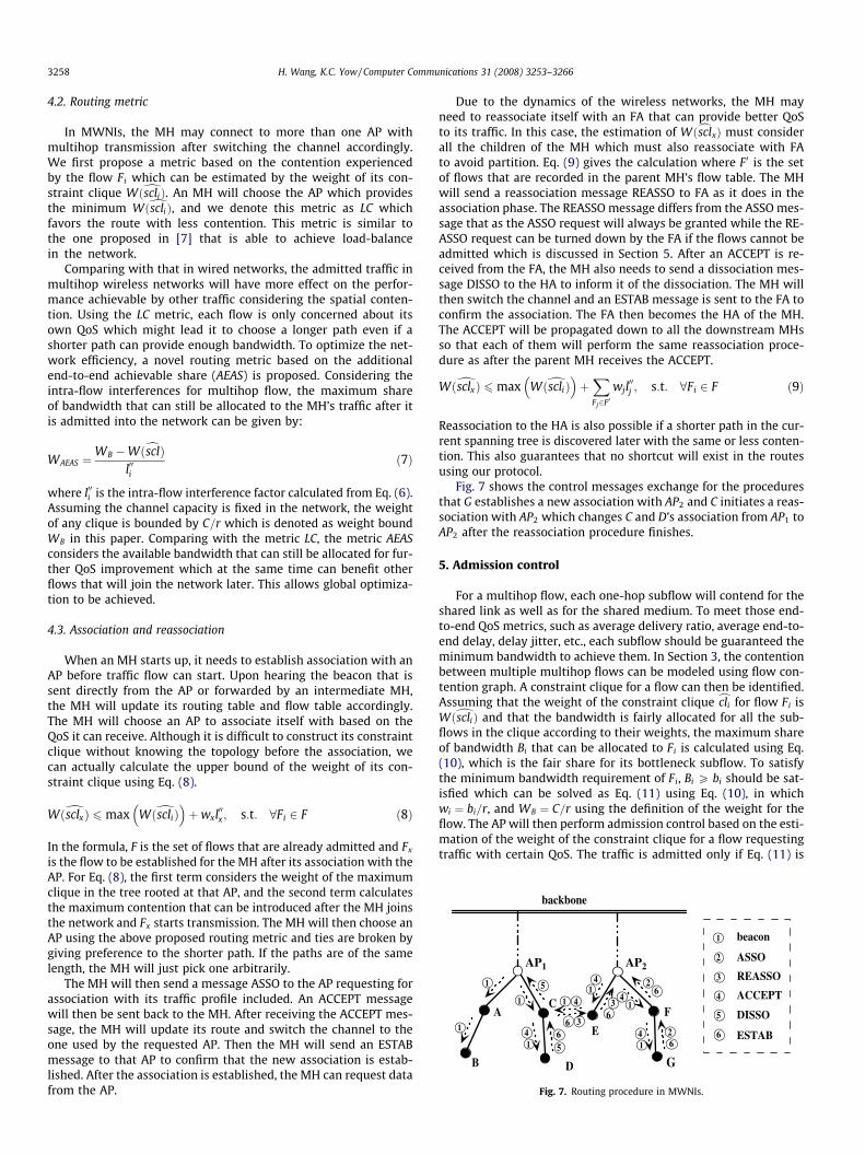
Fig. 7. Routing procedure in MWNIs.
3258 H. Wang, K.C. Yow / Computer Communications 31 (2008) 3253–3266
4.2. Routing metric
In MWNIs, the MH may connect to more than one AP withmultihop transmission after switching the channel accordingly.We first propose a metric based on the contention experiencedby the flow Fi which can be estimated by the weight of its con-straint clique WðdscliÞ. An MH will choose the AP which providesthe minimum WðdscliÞ, and we denote this metric as LC whichfavors the route with less contention. This metric is similar tothe one proposed in [7] that is able to achieve load-balancein the network.
Comparing with that in wired networks, the admitted traffic inmultihop wireless networks will have more effect on the perfor-mance achievable by other traffic considering the spatial conten-tion. Using the LC metric, each flow is only concerned about itsown QoS which might lead it to choose a longer path even if ashorter path can provide enough bandwidth. To optimize the net-work efficiency, a novel routing metric based on the additionalend-to-end achievable share (AEAS) is proposed. Considering theintra-flow interferences for multihop flow, the maximum shareof bandwidth that can still be allocated to the MH’s traffic after itis admitted into the network can be given by:
WAEAS ¼WB �WðcsclÞ
l00ið7Þ
where l00i is the intra-flow interference factor calculated from Eq. (6).Assuming the channel capacity is fixed in the network, the weightof any clique is bounded by C=r which is denoted as weight boundWB in this paper. Comparing with the metric LC, the metric AEASconsiders the available bandwidth that can still be allocated for fur-ther QoS improvement which at the same time can benefit otherflows that will join the network later. This allows global optimiza-tion to be achieved.
4.3. Association and reassociation
When an MH starts up, it needs to establish association with anAP before traffic flow can start. Upon hearing the beacon that issent directly from the AP or forwarded by an intermediate MH,the MH will update its routing table and flow table accordingly.The MH will choose an AP to associate itself with based on theQoS it can receive. Although it is difficult to construct its constraintclique without knowing the topology before the association, wecan actually calculate the upper bound of the weight of its con-straint clique using Eq. (8).
WðdsclxÞ 6 max WðdscliÞ� �
þwxl00x ; s:t: 8Fi 2 F ð8Þ
In the formula, F is the set of flows that are already admitted and Fx
is the flow to be established for the MH after its association with theAP. For Eq. (8), the first term considers the weight of the maximumclique in the tree rooted at that AP, and the second term calculatesthe maximum contention that can be introduced after the MH joinsthe network and Fx starts transmission. The MH will then choose anAP using the above proposed routing metric and ties are broken bygiving preference to the shorter path. If the paths are of the samelength, the MH will just pick one arbitrarily.
The MH will then send a message ASSO to the AP requesting forassociation with its traffic profile included. An ACCEPT messagewill then be sent back to the MH. After receiving the ACCEPT mes-sage, the MH will update its route and switch the channel to theone used by the requested AP. Then the MH will send an ESTABmessage to that AP to confirm that the new association is estab-lished. After the association is established, the MH can request datafrom the AP.
Due to the dynamics of the wireless networks, the MH mayneed to reassociate itself with an FA that can provide better QoSto its traffic. In this case, the estimation of WðcsclxÞ must considerall the children of the MH which must also reassociate with FAto avoid partition. Eq. (9) gives the calculation where F 0 is the setof flows that are recorded in the parent MH’s flow table. The MHwill send a reassociation message REASSO to FA as it does in theassociation phase. The REASSO message differs from the ASSO mes-sage that as the ASSO request will always be granted while the RE-ASSO request can be turned down by the FA if the flows cannot beadmitted which is discussed in Section 5. After an ACCEPT is re-ceived from the FA, the MH also needs to send a dissociation mes-sage DISSO to the HA to inform it of the dissociation. The MH willthen switch the channel and an ESTAB message is sent to the FA toconfirm the association. The FA then becomes the HA of the MH.The ACCEPT will be propagated down to all the downstream MHsso that each of them will perform the same reassociation proce-dure as after the parent MH receives the ACCEPT.
WðdsclxÞ 6max Wðdscli Þ� �
þXFj2F0
wjl00j ; s:t: 8Fi 2 F ð9Þ
Reassociation to the HA is also possible if a shorter path in the cur-rent spanning tree is discovered later with the same or less conten-tion. This also guarantees that no shortcut will exist in the routesusing our protocol.
Fig. 7 shows the control messages exchange for the proceduresthat G establishes a new association with AP2 and C initiates a reas-sociation with AP2 which changes C and D’s association from AP1 toAP2 after the reassociation procedure finishes.
5. Admission control
For a multihop flow, each one-hop subflow will contend for theshared link as well as for the shared medium. To meet those end-to-end QoS metrics, such as average delivery ratio, average end-to-end delay, delay jitter, etc., each subflow should be guaranteed theminimum bandwidth to achieve them. In Section 3, the contentionbetween multiple multihop flows can be modeled using flow con-tention graph. A constraint clique for a flow can then be identified.Assuming that the weight of the constraint clique ccli for flow Fi isWðdscliÞ and that the bandwidth is fairly allocated for all the sub-flows in the clique according to their weights, the maximum shareof bandwidth Bi that can be allocated to Fi is calculated using Eq.(10), which is the fair share for its bottleneck subflow. To satisfythe minimum bandwidth requirement of Fi, Bi P bi should be sat-isfied which can be solved as Eq. (11) using Eq. (10), in whichwi ¼ bi=r, and WB ¼ C=r using the definition of the weight for theflow. The AP will then perform admission control based on the esti-mation of the weight of the constraint clique for a flow requestingtraffic with certain QoS. The traffic is admitted only if Eq. (11) is

H. Wang, K.C. Yow / Computer Communications 31 (2008) 3253–3266 3259
satisfied, otherwise the MH will send request later to check thebandwidth availability.
Bi ¼wiC
WðdscliÞð10Þ
Wðdscli Þ 6WB ð11Þ
In this paper, we assume the minimum bandwidth requirement willbe guaranteed after it is admitted. For those rate-adaptive applica-tions, better QoS can be supported if there is additional bandwidthavailable and the traffic profile at the AP will get updated accord-ingly based on the negotiation. Also, rate-control mechanism suchas leaky bucket can be planted at the admission controller to regu-late those uncooperative real-time traffic.
6. Hierarchical scheduling
A hierarchical scheduling scheme is proposed to achieve the fol-lowing objectives: (1) to guarantee the minimum bandwidthrequirement for real-time traffic which is specified in the respec-tive traffic profile after it is admitted into the network, (2) to en-hance delay performances for admitted real-time traffic and (3)to optimize the fairness among best-effort traffic. As is shown inFig. 8, we proposed a two-level scheduling. On the first level, theavailable link capacity is divided between two logical schedulingservers which are denoted as virtual servers VSRT and VSBE. Whenthe outgoing link is idle, one virtual server will be selected whichwill send real-time packets or best-effort packets into the network.Virtual servers can use weighted fair queueing algorithms to sche-dule the flows, thus the fairness among flows of the same type canbe optimized. To enhance the delay performance for real-time traf-fic, a novel scheduling algorithm is proposed to heuristically adjustthe share of bandwidth for the virtual server.
6.1. Design issues
One important issue in our work is to guarantee that the con-tention incurred by admitting best-effort traffic will not affectthe QoS for admitted real-time traffic. The link capacity is usuallyassumed to be fixed for a wired link, however, this does not standfor a wireless link. In wireless networks, after a head-of-line (HOL)packet is scheduled, it has to be further scheduled by the MAC be-fore being actually sent to the physical channel. Otherwise, simul-taneous transmissions on the same channel from other nodes willinterfere with it and prevent it from being correctly demodulatedby the intended receiver. For links that are contending for the samechannel, i.e. within the interference range of each other, theachievable capacity for each link is to a large extent constrainedby the topology (assuming that the MAC has no bias). Thus in wire-less network, scheduling should be applied to multiple links thatare contending for the same shared medium so as to fairly allocatebandwidth to all flows. In our framework, only the AP is in chargeof the scheduling, thus the burden at the MHs is greatly alleviated.
Virtual Server Virtual Server
Outgoing Link
... ...
real - time flows best - effort flows
scheduling for virtual servers
scheduling for packets
Fig. 8. Hierarchical scheduling for real-time flows and best-effort flows.
Meanwhile, reducing delay to a small value for the delivereddata is also necessary to present satisfactory service to the endusers. Generally, as the network load increases, the end-to-end de-lay will increase accordingly due to the queueing delays and thebackoff delays during channel contention. After the load exceedsa certain level near the channel capacity, contention at some area(bottleneck area) will cause the queues of the links at that areato gradually build up and the delay for the packets will increasein a much steeper slope. As the load increases after that point,the network throughput starts to grow at a slower rate since morepackets are dropped as queues overflow and collisions occur. Ifleave such congestion uncontrolled, the poor end-to-end perfor-mance will render the delivered real-time traffic useless. In ourwork, it is desirable to control the network load at the bottleneckarea and keep it below the level of causing congestion. This canbe achieved by sacrificing some bandwidth which otherwise willbe used by best-effort traffic. Such bandwidth sacrifice is accept-able since the QoS for real-time traffic can be greatly enhancedand at the same time, best-effort traffic can still use most of theavailable bandwidth. Also, with the network being slightly under-utilized, the whole system will also be more stable and such stabil-ity is especially important to be pursued in multihop wirelessnetworks. In our work, the share for best-effort traffic is heuristi-cally controlled by the scheduler to enhance the QoS for admittedreal-time traffic.
6.2. Scheduling for virtual servers
The virtual servers will be scheduled according to their weightswhich are assigned in proportion to the corresponding allocatedbandwidth. For VSRT , its weight WRT is just the sum of the weightsof all real-time flows that are queued at the server:
WRT ¼X
wðf Þ; f 2 FRT ð12Þ
Considering all the real-time subflows that interfere with the AP(i.e. interfere with the subflows sent from the AP), cliques can beconstructed based on their traffic profiles as described in Section3. The one with the largest weight is the AP-constraint cliquecsclAP which constrains the maximum achievable capacity of theAP.1 The AP will share the channel capacity with the MHs that initi-ate subflows which are included in csclAP , and the weight of the AP-constraint clique WðcsclAPÞ represents the minimum bandwidth thatshould be allocated to admitted real-time traffic assuming that max-imum spatial reuse is achieved. The rest of the channel capacity cWcan then be allocated to best-effort flows based on Eq. (13). How-ever, considering multihop transmission, the actual weight WBE thatshould be assigned for best-effort traffic at the AP will be less thancW BE, i.e. WBE 6
cW .
cW ¼WB �WðcsclAPÞ ð13Þ
In a multihop wireless network, the end-to-end delay for apacket will consist of the queueing delays at all the forwardingnodes as well as the backoff times in each node to contend forthe medium. In MWNIs, the AP is the entry point for all traffic flowsand thus all traffic will contend for the same link there. The conten-tion experienced by the packet will be less as it is propagated fur-ther downlink, thus the delay at the AP will contribute to a largeextent the end-to-end delay for the packet. In MWNIs, if theamount of best-effort traffic being admitted exceeds a certainthreshold, the intensified contention with real-time traffic for boththe shared link and the shared medium will cause the real-timepackets to be detained much longer in the queue. It is thereforedesirable to find the ideal share for best-effort traffic so that the
1 To be more accurate, should be the outgoing link of the AP.

3260 H. Wang, K.C. Yow / Computer Communications 31 (2008) 3253–3266
contention will not jeopardize the QoS of the real-time traffic andat the same time the available network bandwidth can be effi-ciently utilized by the best-effort traffic. In our framework, an algo-rithm based on additive increase and multiplicative decrease(AIMD) is used to control the share that is allocated to best-efforttraffic, as shown in Algorithm 1, where avgRT is the average queuesize of VSRT , d is multiplicative decrease factor that is set between 0and 100, a is a fixed value to control the additive increase, and cW BE
is an upper bound to prevent WBE from exceeding cW . In our AIMDalgorithm, cW BE ¼ cW .
Algorithm 1. AIMD control of WBE
/* called every T second period */if avgRT > maxth then
WBE WBEð1� d=100Þelse if avgRT 6 minth then
WBE WBE þ aif WBE > cW BE then
WBE cW BE
end ifend if
Since real-time packets are scheduled one-by-one by the VSRT ,its queue size QRT can be taken as the number of real-time packetsthat are waiting for the scheduling at that moment. A low-passfilter is used to calculate its average queue size avgRT . As shownin Eq. (14) where a is a parameter to control how much the pasthistory impacts the calculation. With a larger avgRT , real-timepackets will on average wait for a longer time before being trans-mitted. In our algorithm, if the avgRT exceeds a maximum thresh-old maxth, which indicates a possible QoS-impaired event beingdetected, a d% decrease of WBE is then triggered to alleviate thecontention. When the avgRT drops below a minimum thresholdminth, WBE is increased by a to allow more best-effort traffic tobe scheduled to utilize the available bandwidth.
avgRT ¼ ð1� aÞavgRT þ aQRT ð14Þ
With WRT and WBE being assigned to VSRT and VSBE respectively, theweighted fair queueing is used to schedule the servers. Each virtualserver VSi maintains the following states: (Si, Fi, Qi), where Si and Fi
represent the virtual start and finish time as defined in [8], and Qi isthe queue size of the virtual server which is equal to the number ofpackets that are queued at the corresponding server. The schedulingis implemented as follows:
(1) When a packet with the size Pi arrives at the head of thequeue of VSi, the virtual start and finish time are updatedaccording to the following
2 A screquests
Si ¼Fi; Q i 6¼ 0maxðFi;VÞ; Q i ¼ 0
�ð15Þ
Fi ¼ Si þPi
Wið16Þ
where Qi is the queue size of the virtual server just beforethe moment the packet arrives, V is the virtual time main-tained by the AP and Wi is the weight for the virtual server.
(2) When the AP senses that the channel is idle, Algorithm 2 willbe executed to select the virtual server to schedule.
It should be noted that such a scheduling policy is non-work-conserving2 for best-effort traffic when real-time traffic is admitted
heduling policy is said to be work-conserving if it never idles when there arewaiting to be scheduled.
since the rate control of best-effort traffic is needed to enhance theperformance for real-time traffic. When no real-time traffic is admit-ted, WBE ¼WB so the best-effort traffic can fully utilize thebandwidth.
Algorithm 2. Schedule the virtual server when the outgoing link isidle
if QRT > 0&&ðQBE > 0&&SBE 6 VÞ thenselect VSi with the minimum finish time to schedule (ties arebroken arbitrarily)
else if QRT > 0 thenselect VSRT to schedule
else if SBE 6 V&&QBE > 0 thenselect VSBE to schedule
elseselect none
end if
6.3. Scheduling for packets
As we assume that admitted real-time flows will transmit trafficconforming to their traffic profiles, their fair share can always beguaranteed once there is enough bandwidth being allocated toVSRT . In our implementation, when the virtual server is idle, thepackets from real-time flows will be scheduled in the FIFO orderbased on their arrival time at VSRT .
The conforming assumption for real-time traffic cannot be ap-plied to best-effort traffic which is usually controlled by the trans-port protocol like TCP to probe the maximum available bandwidth.For best-effort traffic, packets from the same flow are stored in thesame queue in the FIFO order and the virtual server VSBE will sche-dule the flows using WFQ [9,10] assuming they are of the sameweight.
6.4. Enhanced stability for AIMD control (EAIMD)
The weight of the VSBE determines the share of bandwidthallocated for best-effort traffic which is topology-dependentand hard to track considering the characteristics of best-efforttraffic. In HSWFQ, WBE is controlled by the AIMD algorithm toapproximate the ideal share in the current topology. However,there may be a gap between the share of admitted best-efforttraffic and its ideal share due to the mismatch between theAIMD control and the flow control of best-effort traffic. Sucha gap can be positive if the share of admitted best-effort trafficis larger than its ideal share which is caused by the weightbeing increased before the actually admitted traffic fully utilizesthe allocated share. The gap can be negative if the share ofadmitted best-effort traffic is less than what it was alloweddue to the slow additive increase of the weight after a multipli-cative decrease. With a large positive gap, the burst of admittedbest-effort traffic will harm the QoS for admitted real-time traf-fic. On the other hand, with a large negative gap, the availablenetwork bandwidth cannot be fully utilized. Such large gapswill cause the performance of the AIMD control to oscillate be-tween overloading and underutilization.
To enhance the stability of the AIMD control, we propose tocontrol cW BE so as to prevent WBE from deviating too much fromthe ideal value. This helps to reduce both the positive gap andthe negative gap, and thus enables the network to convergeover time. When the AIMD algorithm is executed by the AP,QoS-impaired event will be detected if the average queue sizeof VRT exceeds maxth. The queue size at that time Q RT is used

AP1
AP2 AP3
AP0 I II
III IV
Table 3Notations used in Section 6
w(f) The weight assigned to flow f in proportion to its minimum bandwidthrequirement
FRT The set of real-time flowsFBE The set of best-effort flowsVSRT The virtual server to schedule all real-time flowsVSBE The virtual server to schedule all best-effort flowsWRT The weight assigned to VSRT which is in proportion to its allocated
bandwidthWBE The weight assigned to VSBE which is in proportion to its allocated
bandwidthcW The maximum weight could be assigned to VSBEcW BE Upper bound of WBE
WðcsclAPÞ The weight of the AP-constraint cliquea Additive increase rated Multiplicative decrease factora Queue weightmaxth Maximum threshold for queueminth Minimum threshold for queueb Threshold to execute shaping control of WBE
s Shaping factor in EAIMD
H. Wang, K.C. Yow / Computer Communications 31 (2008) 3253–3266 3261
as a reference for enhanced AIMD (EAIMD) as depicted inAlgorithm 3.
Algorithm 3. Enhanced AIMD
/* called upon QoS-impaired detected */if QRTðtÞ > b thencW BE ¼ cW BE � s=100� cWendif
In Algorithm 3, b is a parameter that determines the minimalqueueing delay of real-time packets at the AP and s is a factor toshape the maximum weight of the best-effort traffic. When theðbþ 1Þth packet arrives at VSRT with its queue size of b at thatmoment, it has to wait until all the b packets queued before itare all sent out, so Tbþ1
q PPb
i¼1tipr where Tbþ1
q is the queueing de-lay for the ðbþ 1Þth packet and ti
pr is the propagation time for theith packet. Since the multiplicative decrease of WBE will be in-voked when avgRT exceeds the maximum threshold, the queuesize of VSRT should be controlled without deviating too much be-yond maxth. By setting b�maxth, if QRT > b and avgRT > maxth
are detected together, it is of high probability that the cW is largerthan the ideal share which will allow an excessive burst of best-effort traffic being admitted and harm the QoS for admitted real-time traffic.
Unlike AIMD, in which additive increase factor a and multiplica-tive decrease factor d work in opposite direction to control WBE,EAIMD is triggered only when cW is larger than the ideal sharefor best-effort traffic and eventually keeps WBE below the ideal le-vel by shaping its upper bound cW BE. The stability of AIMD is thusenhanced by the one-way change in EAIMD. There might be a neg-ative gap after executing EAIMD because it is hard to find the idealshare for best-effort traffic. The parameter s is thus set conserva-tively to allow efficient utilization of the network resources.
This algorithm assumes that the QoS of real-time traffic isharmed by excessive admitted best-effort traffic. In wireless net-works, a link failure due to node movement or the dynamics ofthe channel (multipath, fading, etc.) will also impact the QoS forreal-time traffic. Such events are usually aware by the routing pro-tocols (the dynamics of the channel is also indicated as temporarylink failure at the routing protocol), and they can be easily filteredout without affecting our algorithm.
6.5. Parameter analysis
In our heuristic algorithm, the achievable performance greatlydepends on the choice of the parameters. There are a few parame-ters that are not discussed in detail in the above section, and a briefanalysis is provided here to guide the choosing of these parametersin the implementation.
� a and maxth a controls how the history impacts the averagequeue size. An appropriate value should be set to filter out tran-sient QoS violation. Similar analysis as used in RED [11] isapplied in our algorithm.Assuming that the queue of VSRT is ini-tially empty, i.e. an average queue size of zero, and a burst of Lpackets arrives. After the Lth packet arrives at the queue, theaverage queue size avgL is
avgL ¼XL
i¼1
iað1� aÞL�i ¼ Lþ 1þ ð1� aÞLþ1 � 1a
Given maxth and that the burst of L real-time packets are allowedto arrive at the AP, a should be set to satisfy the equationavgL < maxth. To guarantee the delay performance of real-time
traffic, a small value for maxth is desirable to allow the detectionof possible QoS-impaired event. Given maxth ¼ 0:5 and L ¼ 3, forexample, it is necessary to choose a 6 0:0884.
� minth After QoS-impaired is detected, the bandwidth share forbest-effort traffic is reduced which will grant more chances forthe detained real-time packets in the queue to be sent out.Assuming that the average queue size is maxth at that moment,and that the queue becomes empty and remains empty beforethe arrival of next packet if the congestion is alleviated, the aver-age queue size avgM after the Mth arrival packet is
avgM ¼maxthð1� aÞM ð17Þ
which is deduced from Eq. (14). The value of M provides an esti-mation for the network state. If consecutive M real-time packetsarrive at VSRT which has an empty queue, it is highly possiblethat the network still has available bandwidth to accommodatemore traffic which supports the equation minth 6 avgM . In ourwork, M is equal to L which is the number of burst of packetsas discussed above.
The notations used in this section are given in Table 3.
7. Performance evaluation
7.1. Simulation setup
In this section, the performance of our proposal is evaluated inNS-2 [12]. IEEE 802.11 DCF is used as the underlying MAC protocol.The effective transmission range and the interference range are setto 250 m, and the data rate of the channel is set to 2 Mbp. Two-rayground propagation model is used in our simulation.
A simulation area of 1200 m by 1200 m is equally divided into 4regions with one AP placed at the center of each region as shown in
Fig. 9. Placement of the APs.

Fig. 11. Efficiency of admission control: average end-to-end delay of real-timetraffic.
Fig. 12. Efficiency of admission control: aggregate throughput of real-time traffic.
3262 H. Wang, K.C. Yow / Computer Communications 31 (2008) 3253–3266
Fig. 9, and each AP is pre-assigned a non-overlapping channel.There are totally 120 MHs with 30 of them evenly distributed ineach region. All real-time traffic used in this section is sent in con-stant bit rate (CBR) using UDP with a packet size of 512 bytes andthe weight of the real-time flow is calculated based on its data ratewhich is assumed to be the minimum bandwidth required to sup-port acceptable service. Newreno TCP with default parameters setin NS-2 is used to send best-effort traffic with a packet size of 128bytes.
To simulate the dynamic traffic and to evaluate the efficiency ofour proposal, traffic flows will start one by one in intervals of 10seconds and statistics will be collected after all flows starttransmission.
7.2. Efficiency of admission control
In this scenario, there are 20 real-time flows with the same datarate. Among all the MHs, 10 of them in region II and another 10 inregion III are selected as the traffic sinks. Various QoS requirementsare simulated by varying the data rate of real-time traffic andupdating the traffic profiles accordingly.
The value of WB should reflect the effective channel capacity inthe network. Based on the analysis of the maximum throughput ofIEEE 802.11 MAC in [13], the maximum throughput can be calcu-lated which is about 56% of the raw channel rate assuming theaverage packet size is 512 bytes. Based on this estimate, WB canbe calculated since the values for C and r are all fixed for a certainsystem.
We first check the QoS performance for the admitted real-timetraffic. As shown in Fig. 10, admitted real-time traffic can achieve ahigh delivery ratio with both routing metrics if admission control isperformed at the APs. With an average of above 98% of admittedpackets being successfully delivered with various QoS require-ments, the effectiveness of admission control that the flows beingadmitted will be given their required bandwidth is validated.Meanwhile, if all flows are admitted into the network withoutadmission control (for the metric LC only), the performance willdeteriorate greatly after the load exceeds a certain point, whichis at about 2500 Kbps in our simulation. When the load keepsincreasing, a larger delay will occur for the delivered data as shownin Fig. 11. At the same time, the aggregate network throughput in-creases slowly after that point as shown in Fig. 12.
7.3. Efficiency of routing metric
We then study the scenarios with the coexistence of best-efforttraffic and real-time traffic. Besides the 20 real-time flows that areused in the above scenarios, in each region I-IV in the simulation
Fig. 10. Efficiency of admission control: average delivery ratio of real-time traffic.
area, as shown in Fig. 9, 5 MHs are chosen as the best-effort trafficsinks which are all one hop away from the AP located at the centreof the region. To fairly compare the performance of different rout-ing metrics, admission control is performed at the APs. From theresults presented in Section 7.2, it is observed the networkthroughput ceases to increase after reaching about 3000 Kbps. Soonly the simulation results with total real-time traffic requirementbetween 500 Kbp and 3000 Kbp are presented in this section.
In Fig. 13, the aggregate throughput of best-effort traffic andreal-time traffic is shown. First, it should be noted that the perfor-
Fig. 13. Aggregate traffic throughput with different routing metrics.
H. Wang, K.C. Yow / Computer Communications 31 (2008) 3253–3266 3263
mance of the real-time traffic is not affected too much by the coex-isting best effort traffic. This is because UDP sources are not subjectto the same adaptation as TCP and also no end-to-end reliability isprovided by UDP, while TCP is flow-controlled and will only utilizethe available bandwidth. We can observe that the performance ofreal-time traffic using different routing metrics is almost the same.However, the performance of best-effort traffic achieved by usingthe routing metric AEAS is much better than that achieved by usingthe metric LC, which has up to 100% improvement in thethroughput.
To better understand the performance difference for best-efforttraffic using different routing metrics, in Tables 4 and 5, the admit-ted best-effort traffic and real-time traffic from each AP is mea-sured. We can observe from the tables that real-time trafficdistributes more evenly among all the channels if using the metricLC; on the other hand, best-effort traffic admitted from each AP isnot that balanced. In this simulation, the distribution of real-timetraffic affects the distribution of admitted best-effort traffic. Thiscan be explained from two aspects: First, by using the metric LC,more real-time traffic will be served through longer paths, e.g.from AP0 and AP3 as shown in Table 4. This is because using themetric LC will balance the admitted real-time traffic among allavailable channels which even requires the MHs to associate witha farther AP but less loaded. The additional multihop transmission
Table 4Per-AP admitted traffic: use the metric LC
Real-time traffic (Kbp) Best-effort traffic (Kbp) Real-time traffic (Kbp)
AP0 AP1 AP2 AP3 AP0 AP1 AP2 AP3
500 224 91 114 108 109 138 148 981000 135 49 37 91 216 315 294 1581500 99 40 32 75 325 472 443 2362000 82 42 24 50 430 635 614 3702500 54 29 31 56 432 838 789 4833000 71 2 23 47 455 971 878 486
Table 5Per-AP admitted traffic: use the metric AEAS
Real-time traffic (Kbp) Best-effort traffic (Kbp) Real-time traffic (Kbp)
AP0 AP1 AP2 AP3 AP0 AP1 AP2 AP3
500 323 273 276 309 25 212 207 501000 293 215 226 287 78 414 393 981500 246 177 175 238 163 546 575 1922000 138 168 116 149 348 594 779 3282500 94 94 53 101 406 812 890 4323000 35 2 35 53 576 1001 878 516
Fig. 14. Average route length of best-effort flows with different routing metrics.
uses more bandwidth, the admitted best-effort traffic is thus af-fected since best-effort traffic only uses the available bandwidth.Second, best-effort traffic will take longer paths to be served usingthe metric LC, as shown in Fig. 14. By checking the trace files for thesimulation using the metric LC, we found that the best-effort trafficsinks in regions II and III tend to associate with AP0 or AP3 whichwill use longer paths for those MHs in region I and IV. Further anal-ysis reveals the reason: all the real-time traffic sinks are in region IIand III, it is of higher probability that AP1 and AP2 are more loadedwhich ‘‘lures” the best-effort traffic sinks in region II and III to asso-ciate with AP0 and AP3.
7.4. Efficiency of hierarchical scheduling
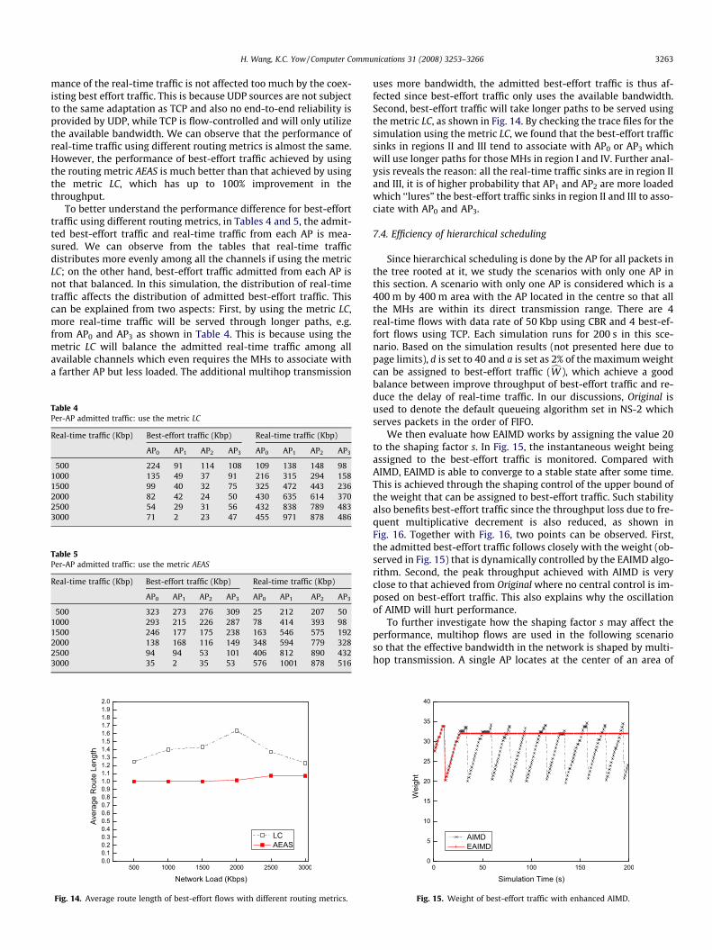
Since hierarchical scheduling is done by the AP for all packets inthe tree rooted at it, we study the scenarios with only one AP inthis section. A scenario with only one AP is considered which is a400 m by 400 m area with the AP located in the centre so that allthe MHs are within its direct transmission range. There are 4real-time flows with data rate of 50 Kbp using CBR and 4 best-ef-fort flows using TCP. Each simulation runs for 200 s in this sce-nario. Based on the simulation results (not presented here due topage limits), d is set to 40 and a is set as 2% of the maximum weightcan be assigned to best-effort traffic (cW ), which achieve a goodbalance between improve throughput of best-effort traffic and re-duce the delay of real-time traffic. In our discussions, Original isused to denote the default queueing algorithm set in NS-2 whichserves packets in the order of FIFO.
We then evaluate how EAIMD works by assigning the value 20to the shaping factor s. In Fig. 15, the instantaneous weight beingassigned to the best-effort traffic is monitored. Compared withAIMD, EAIMD is able to converge to a stable state after some time.This is achieved through the shaping control of the upper bound ofthe weight that can be assigned to best-effort traffic. Such stabilityalso benefits best-effort traffic since the throughput loss due to fre-quent multiplicative decrement is also reduced, as shown inFig. 16. Together with Fig. 16, two points can be observed. First,the admitted best-effort traffic follows closely with the weight (ob-served in Fig. 15) that is dynamically controlled by the EAIMD algo-rithm. Second, the peak throughput achieved with AIMD is veryclose to that achieved from Original where no central control is im-posed on best-effort traffic. This also explains why the oscillationof AIMD will hurt performance.
To further investigate how the shaping factor s may affect theperformance, multihop flows are used in the following scenarioso that the effective bandwidth in the network is shaped by multi-hop transmission. A single AP locates at the center of an area of
Fig. 15. Weight of best-effort traffic with enhanced AIMD.

Fig. 16. Aggregated throughput of best-effort traffic with enhanced AIMD.
3264 H. Wang, K.C. Yow / Computer Communications 31 (2008) 3253–3266
1000 m by 1000 m with 36 MHs evenly distributed in it. Takingreference from the AP, 2 1-hop MHs and 2 2-hop MHs are selectedas the sinks for best-effort flows, and 2 2-hop MHs are selected asthe sinks for real-time traffic with data rate of 50 Kbp. Various val-ues of s between 0 and 50 are used for the following simulationswhere s ¼ 0 represents no shaping control, i.e. AIMD.
From Fig. 17, it is observed that the delay of real-time traffic willincrease as s decreases since the burst of best-effort traffic willgreatly harm the performance of real-time traffic. It is further ob-served from Fig. 18 that such burst contributes little to improvethe network utilization as the admitted best effort traffic is aboutthe same when s is set to values between 5 and 30, which however,
Fig. 17. Average end-to-end delay of real-time traffic with different shaping factor.
Fig. 18. Aggregate throughput of best-effort traffic with different shaping factor.
is still higher than that achieved without using shaping control(s ¼ 0) due to the oscillation of AIMD.
In Fig. 19, the fairness among all admitted best-effort flows ismeasured with the well-known Jain’s fairness index [14] whichcan be calculated by:
FIðxÞ ¼P
xið Þ2
nP
x2i
� � ð18Þ
where xi is the amount of admitted traffic from the best-effort flowFi and n is the number of admitted best-effort flows. An FI of 1means all the best-effort flows get the exact same share of band-width. It can be seen from the figure that s has negligible effecton the fairness among all best-effort flows. Comparing with the Ori-ginal scheme that does not implement fair queueing, our proposedhierarchical scheduling based on weighted fair queueing can pro-vide a fair share for all best-effort flows.
7.5. Efficiency of QoS framework
In the following simulations, the efficiency of the QoS frame-work is evaluated to check how it can optimize the QoS of real-time traffic with various requirements and maximize the networkefficiency. The same scenario used in Section 7.3 is used for thissimulation and the traffic consists of 20 real-time flows and 20best-effort flows. In the following simulations, our proposed QoSframework which is FCGQR using the routing metric AEAS and withthe hierarchical scheduling (HS) as is denoted ‘‘FCGQR+AEAS withHS” in the figures, which is compared with ‘‘FCGQR+AEAS w/o HS”that does not implement the hierarchical scheduling algorithm.
Fig. 19. Fairness index of best-effort traffic with different shaping factor.
Fig. 20. Average end-to-end delay of real-time traffic.

Fig. 21. Average delivery ratio of real-time traffic.
H. Wang, K.C. Yow / Computer Communications 31 (2008) 3253–3266 3265
The QoS of admitted real-time traffic is shown in Figs. 20 and21. With all components working closely together, both the aver-age end-to-end delay and the average delivery ratio are not im-pacted very much by the varying QoS requirement. However,without hierarchical scheduling (i.e. best-effort traffic is not con-trolled), the performance of admitted real-time traffic is unpredict-able, and an average of 5% admitted real-time traffic is lost. There isalso 10 times more delay incurred due to the contention with best-effort traffic. It can also be observed that after the network re-source is almost all allocated for real-time traffic (after the back-logged real-time traffic exceeds 3000 Kbps), there is littlethroughput improvement for best-effort traffic using scheme with-out HS over scheme with HS, as is shown in Fig. 22. However, theQoS of real-time traffic in both delay and delivery ratio is stillworse than that achieved with our proposed QoS framework, asshown in Fig. 20 and Fig. 21. This shows the importance of keepingnetwork stable by leaving some bandwidth unused as a ‘‘bufferzone”. In our QoS framework, real-time traffic is regulated withadmission control while best-effort traffic is policed with schedul-ing at the AP, which optimizes the efficiency of the network withdynamic traffic.
8. Related work
8.1. Multi-channel wireless networks
In recent years, there are several studies on the routing problemin multihop wireless networks where the dynamic switching ofchannels can be supported by the traditional IEEE 802.11 basednetwork interface. Assuming that the existing single-channel
Fig. 22. Average network throughput.
MAC is used, the main focuses of those works are channel assign-ment and routing algorithms.
In [15,16], Raniwala et al. propose an architecture and sev-eral algorithms to support multiple channels with multiple NICsin wireless mesh networks (WMNs). A centralized channelassignment algorithm is proposed in [15] that assumes eachnode has multiple NICs that can effectively utilize the networkbandwidth without incurring network partition. Their work isfurther extended to a distributed channel assignment algorithmproposed in [16]. A load-balancing routing protocol is also in-cluded which can adapt to traffic load changes as well as net-work failures.
In [17], a multi-channel routing protocol called MCRR is pro-posed for multihop ad hoc networks. Single NIC and existing sin-gle-channel MAC can be supported by assigning the samechannel to all nodes in the same flow. For nodes that are support-ing more than one flow, periodic channel-switching must beperformed that requires strict synchronization among the neigh-boring nodes. In [7], routing and channel assignment problemsare studied in a multihop wireless network with infrastructuresupport where each node is assumed to be equipped with a singleNIC. Although similar assumptions are used in their work and inours, the focus on QoS enhancement differentiates our work fromtheirs. First, in [7], load-balance is achieved that each MH will asso-ciate with the AP with the least load. However, in our work, an MHwill associate with an AP with more residual bandwidth whichdoes not necessarily balance the load immediately. Second, theMH will switch channel to associate with a less-loaded AP in theirwork. In our work, fast reaction to the network dynamics is possi-ble if QoS violation, such as high delay and low throughput, is de-tected locally at the MH, and the MH will switch association withother AP for better QoS.
8.2. QoS framework
FQMM [18] is the first QoS model proposed for small tomedium size MANETs. In FQMM, only traffic with the highestpriority is given per-flow granularity as in IntServ [19] whileother traffic is given per-class provisioning as in DiffServ [20],and the traffic is policed at the source node. However, FQMMonly presents a general QoS model for MANETs, the detailsfor its various components like resource metering, QoS routingand scheduling are not discussed in depth. In our framework,a similar design philosophy is adopted where the schedulingpolicies are only implemented at the AP which is the entrypoint of all traffic and has enough resources to support complexscheduling algorithms. Mobile hosts only need to maintain real-time traffic information which constitutes only a small part ofthe traffic in the network.
In SWAN [21], dynamic rate control is applied for best-efforttraffic to enhance the end-to-end performance of real-time traffic.However, SWAN assumes most of the network capacity is utilizedby best-effort traffic and only a small proportion is reserved forreal-time traffic. In our work, one objective is to maximize thenumber of real-time traffic that are admitted into the network,while another objective is to optimize throughput for best-efforttraffic by exploiting channel diversity with our QoS routing proto-col. Except for the basic assumption and the network environment,there still exists several major differences between SWAN and ourwork. First, SWAN relies on the underlying routing protocol to findroutes and reserves resources through explicit signaling. However,the contention experienced by the probe message may not be thesame as what the admitted traffic experiences because of inter-flow contention and intra-flow contention. Thus false admissionis likely to occur which will waste the network resources and affectthe network stability. In our work, by cooperating with QoS

3266 H. Wang, K.C. Yow / Computer Communications 31 (2008) 3253–3266
routing, admission control works more efficiently by avoiding theoverburden in the bottleneck region of the network. Such cooper-ation with the routing module will also benefit the discovery of abetter topology which allows more efficient utilization of the net-work resources. Second, the rate control of best-effort traffic inSWAN requires the cooperation from MAC. Instead, our frameworkis designed in a more practical way that most functions are imple-mented at the AP, and all functions are implemented above theMAC layer, thus making our proposal compatible with existingwireless devices.
8.3. Scheduling
In the literature, several scheduling algorithms [2,4,22,23,6]have been proposed for wireless networks to achieve various de-grees of trade-off between the maximization of spatial reuse andmaintaining fairness among flows. Although the centralized algo-rithms like that been proposed in [2,6] provide theoretical solution,they are difficult to be implemented in practical networks. For thedistributed algorithms like that been proposed in [2,4,22,23], onthe other hand, require modification of the MAC to realize per-flowgranularity scheduling with the auxiliary information maintainedand exchanged at each node. Such implementation complexity atthe lower layers is a huge burden for resource-limited mobilenodes and contradicts with our design criteria.
In [24], a two-level hierarchical scheduling scheme is devisedfor the co-existence of QoS flow and best-effort flows. However,their scheme does not consider the contention in the spatial do-main, and their scheduling algorithm is only concerned with band-width requirement and does not consider other important QoSmetrics such as delay which is very sensitive for most real-timeapplications. In our framework, a hierarchical packet schedulingalgorithm is proposed based on a virtual sharing model to bettercharacterize the unique properties of MWNIs, which also providesenhancement to optimize other end-to-end QoS metrics, like delay,for real-time traffic.
9. Conclusion
In this paper, a QoS framework is proposed to support inte-grated services in multihop wireless networks with infrastruc-ture support which consists of three major components. First,a QoS routing algorithm is designed which, by exploiting allavailable channels, is adaptive to the traffic dynamics and isable to discover a global optimized topology. Second, basedon the estimation of the contention in the current topology,admission control is performed at the APs based on the trafficprofiles. Finally, a hierarchical scheduling algorithm is imple-mented at the APs to further enhance the QoS for admittedtraffic. Through exhaustive simulation studies, our design princi-ples are justified and the QoS framework is shown to be able toachieve our objectives.
References
[1] Wireless LAN Medium Access Control (MAC) and Physical Layer (PHY)Specifications, IEEE Standard 802.11, June 1999.
[2] H. Luo, S. Lu, V. Bharghavan, A new model for packet scheduling in multihopwireless networks, in: MobiCom’00: Proceedings of the 6th AnnualInternational Conference on Mobile Computing and Networking, New York,NY, USA, ACM Press, 2000, pp. 76–86.
[3] S. Chakrabarti, A. Mishra, QoS issues in ad hoc wireless networks,Communications Magazine IEEE 39 (2) (2001) 142–148.
[4] B. Li, End-to-end fair bandwidth allocation in multi-hop wireless ad hocnetworks, in: Proceedings of IEEE International Conference on DistributedComputing Systems, 2005, pp. 471–480.
[5] C.H. Papadimitriou, K. Steiglitz, Combinatorial Optimization: Algorithms andComplexity, Dover Publications, 1998.
[6] X.L. Huang, B. Bensaou, On max–min fairness and scheduling in wireless ad-hocnetworks: analytical framework and implementation, in: MobiHoc’01:Proceedings of the 2nd ACM International Symposium on Mobile Ad hocNetworking and Computing. New York, NY, USA, ACM Press, 2001, pp. 221–231.
[7] J. So, N.H. Vaidya, Routing and channel assignment in multi-channel multi-hopwireless networks with single network interface, in: The Second InternationalConference on Quality of Service in Heterogeneous Wired/Wireless Networks(QShine), August, 2005.
[8] J.C.R. Bennett, H. Zhang, Hierarchical packet fair queueing algorithms, IEEE/ACM Transactions on Networking 5 (5) (1997) 675–689.
[9] A. Demers, S. Keshav, S. Shenker, Analysis and simulation of a fair queueingalgorithm, in: SIGCOMM’89: Symposium Proceedings on CommunicationsArchitectures & Protocols, New York, NY, USA, ACM Press, 1989, pp. 1–12.
[10] A.K. Parekh, R.G. Gallager, A generalized processor sharing approach to flowcontrol in integrated services networks: the single-node case, IEEE/ACMTransactions on Networking 1 (3) (1993) 344–357.
[11] S. Floyd, V. Jacobson, Random early detection gateways for congestionavoidance, IEEE/ACM Transactions on Networking 1 (4) (1993).
[12] The Network Simulator ns-2. Available from: http://www.isi.edu/nsnam/ns/.[13] Z. Li, A. Das, A.K. Gupta, S. Nandi, Full auto rate MAC protocol for wireless ad
hoc networks, in: IEE Proceedings Communication, 2004.[14] R. Jain, D. Chiu, W. Hawe, A Quantitative Measure of Fairness and
Discrimination for Resource Allocation in Shared Computer System,Technical Report, December 1984.
[15] A. Raniwala, K. Gopalan, T.C. Chiueh, Centralized channel assignment androuting algorithms for multi-channel wireless mesh networks, SIGMOBILEMob. Comput. Commun. Rev. 8 (2) (2004) 50–65.
[16] A. Raniwala, T.C. Chiueh, Architecture and algorithms for an IEEE 802.11-basedmulti-channel wireless mesh network, in: INFOCOM 2005: Proceedings of the24th Annual Joint Conference of the IEEE Computer and CommunicationsSocieties, vol. 3, 2005, pp. 2223–2234.
[17] J. So N.H. Vaidya, A routing protocol for utilizing multiple channels in multi-hopwireless networks with a single transceiver, Technical Report, October, 2004.
[18] H. Xiao, W.K.G. Seah, A. Lo, K.C. Chua, A flexible quality of service model formobile ad-hoc networks, in: Proceedings of IEEE 51st Vehicular TechnologyConference, vol. 1, 2000, pp. 445–449.
[19] R. Braden, D. Clark, S. Shenker, Integrated services in the internet architecture– an overview, IETF RFC1663 (1994).
[20] S. Blake, D. Black, M. Carlson, E. Davies, Z. Wang, W. Weiss, An architecture fordifferentiated services, RFC 2475 (1998).
[21] G.S. Ahn, A.T. Campbell, A. Veres, L.H. Sun, SWAN: service differentiation instateless wireless ad hoc networks, in: INFOCOM 2002. Proceedings of 21stAnnual Joint Conference of the IEEE Computer and Communications Societies,IEEE, vol. 2, 2002, pp. 457–466.
[22] H. Luo, J. Cheng, S. Lu, Self-coordinating localized fair queueing in wireless adhoc networks, IEEE Transactions on Mobile Computing 3 (1) (2004) 86–98.
[23] H. Luo, S. Lu, A topology-independent fair queueing model in ad hoc wirelessnetworks, in: Proceedings of IEEE International Conference on NetworkProtocols, 2000, pp. 325–335.
[24] S. Chen, Routing Support for Providing Guaranteed End-to-End Quality-of-Service, Ph.D. dissertation, University of IL at Urbana-Champaign, 1999.[Online]. Available from: http://cairo.cs.uiuc.edu/papers/SCthesis.ps.