a reliable instant messenger in erlang: design and …eprints.gla.ac.uk/113709/1/113709.pdf · a...
TRANSCRIPT

A Reliable Instant Messenger in Erlang: Design and
Evaluation
Mario Moro Hernandez, Natalia Chechina, and Phil Trinder
School of Computing ScienceThe University of Glasgow
Glasgow G12 8QQUK
Technical Report TR-2015-002
December 17, 2015

Contents
1 Introduction 2
2 Instant Messenger Design and Implementation 42.1 Idiosyncrasy of the Erlang/OTP Applications . . . . . . . . . 42.2 Architecture of the RD-IM and RSD-IM . . . . . . . . . . . . 5
2.2.1 Server-Side Nodes . . . . . . . . . . . . . . . . . . . . 52.2.2 Client-Side Nodes . . . . . . . . . . . . . . . . . . . . 72.2.3 RSD-IM specific processes . . . . . . . . . . . . . . . . 8
2.3 Supervision Tree . . . . . . . . . . . . . . . . . . . . . . . . . 92.4 Deployment and architectural layout . . . . . . . . . . . . . . 92.5 Auxiliary Non-IM modules used for testing purposes . . . . . 122.6 Summary . . . . . . . . . . . . . . . . . . . . . . . . . . . . . 14
3 Reliability Mechanisms and Message Flow 153.1 D-Erlang Instant Messenger . . . . . . . . . . . . . . . . . . . 15
3.1.1 Handling Exceptions . . . . . . . . . . . . . . . . . . . 153.1.2 Normal Behaviour . . . . . . . . . . . . . . . . . . . . 18
3.2 SD-Erlang Instant Messenger . . . . . . . . . . . . . . . . . . 21
4 Changes to the Original Design 30
5 Evaluation 335.1 Experimental Setup . . . . . . . . . . . . . . . . . . . . . . . 335.2 Experiment 1: Impact of the Number of Servers with No
Failures . . . . . . . . . . . . . . . . . . . . . . . . . . . . . . 335.3 Experiment 2: Impact of the Number of Servers & S groups
with No Failures . . . . . . . . . . . . . . . . . . . . . . . . . 365.4 Experiment 3: Impact of the Number of S groups with No
Failures . . . . . . . . . . . . . . . . . . . . . . . . . . . . . . 395.5 Experiment 4: Impact of Failures . . . . . . . . . . . . . . . . 425.6 Experiment 5: Impact of the Rate of Failures . . . . . . . . . 47
6 Conclusion and Future Work 51
1

Chapter 1
Introduction
This document describes the design and evaluation of two Erlang-basedinstant messenger systems using Distributed Erlang (D-Erlang) and ScalableDistributed Erlang (SD-Erlang). The purpose of these systems is to serveas real-world benchmarks to test the performance of the SD Erlang library.
The Erlang programming language was invented by Joe Armstrong,Robert Virding, and Mike Williams at Ericsson Computer Science Lab in1986. It was conceived ’as a tool to get the job done’ [Arm07a], being this jobto program the second generation of the Ericsson AXE switches. At the be-ginning it was a logic programming language, derived from Prolog [AVW92],designed for ’writting programs that ”run forever”’ [Arm07a], and with theaim of simplifying the programming of telephony applications. Functionallanguage features such as list comprehensions or higher-order functions wereadded few years later. Similarly, support for distribution was added in 1993,years after the first release, and used in production for the first time in 1995with the AXD301 switch [Arm07b].
Today, Erlang is a soft real-time functional language that offers supportfor concurrency, distribution and fault tolerance. It also allows the injectionof code updates without having to stop the application.
Scalable Distributed Erlang (SD Erlang) is an extension of the Erlangdistribution model that let push this limit further, allowing the systems toeither scale more, or given the same size, to use less resources than their dis-tributed Erlang counterparts [CLTG14]. Given the context described above,SD Erlang is particularly useful to increase the scalability of the IM archi-tectures. SD-Erlang has been developed in the RELEASE project, withinthe 7th Framework Programme of the European Commission. The differenttasks performed included the execution of a battery of benchmarks to vali-date this SD Erlang technology. The results obtained to date show that ap-plications written in SD Erlang scale better than their D-Erlang equivalents,penalising neither their performance, nor their reliability models [CLG+15].
2

Glossary
Architecture Conceptual model that defines the structure, behaviour andmore views of a system.
Distributed Erlang System (Also D-Erlang System). System formedout of a number of Erlang nodes that communicate with each other.The system uses standard features of the Erlang language to writedistributed programs.
Scalable Distributed Erlang System (Also SD-Erlang System). Sys-tem formed out of a number of Erlang nodes that communicate witheach other. The system uses features of the Scalable Distributed Er-lang library to write distributed programs.
Process Supervisor Process that monitors all the processes inside thenode which hosts it, and supervisor processes at children nodes (ifany).
3
Chapter 2
Instant Messenger Designand Implementation
2.1 Idiosyncrasy of the Erlang/OTP Applications
The concept of Erlang significantly differes from other programming lan-guages like C or Java. Similarly to other functional languages such as Haskellthe computations are carried out by functions. However, there is a partic-ular type of functions that remain continuously calling to themselves afterperforming some computation. These are called Erlang processes (or simplyprocesses).
An application in Erlang is basically a collection of processes that inter-act with each other to implement a set of requirements. The result of theseinteractions is, obviously, a certain output. But since Erlang was designedfor fault-tolerance, true applications in Erlang are also implement a super-vision tree [CT09]. That is, Erlang applications divide the requirementsbetween different processes that are deployed as a hierarchical implementa-tion of the supervisor/worker design pattern.
As it happens for any other design-patterns, the workers and supervisorshave very defined structures that usually are common within applications.For this reason the OTP framework supplies standardised templates forthese tasks called behaviours, that are aimed to help in the implementationof servers, supervisors, finite state machines and event handlers [CVss].
Behaviours are interesting because they facilitate the reusability of thecode, they uniform the code to a standard and, as they encapsulate somefeatures of the language, allow developers to focus on the application with-out having to worry too much for aspects like fault-tolerance or code hot-swapping. For these reasons industry-standard applications are implementedusing behaviours.
The applications developed for this project do not use behaviours. Atthe design stage it was deemed that they would introduce unnecessary com-
4

plexity. Instead, the supervision tree is directly embedded in the server logicof the different processes that perform monitoring tasks.
The rest of the chapter describes the implementation of the instant mes-senger applications made for the project, the supervision tree, the deploy-ment sequence, and two auxiliary modules that, although they do not belongto the applications, have been used during the experimental sessions.
2.2 Architecture of the RD-IM and RSD-IM
At a first glance to the entities involved, there are no differences betweenRD-IM and RSD-IM applications. This is true to some extent. It is neces-sary to look the code inside the processes to perceive how both differ. Thedissimilarities also affect the way these entities are organised and connectedto each other. However, this policy of applying only the necessary changes,trying to keep the applications the closest possible to each other, ensuresthat only the differences between technologies and not the applications aretested.
The entities of the IM applications are realised in Erlang nodes (Erlangvirtual machines). These nodes host the processes that perform the businessmodel of the applications.
From the point of view of the architecture, the IM applications followa simple client-server architecture. Again, since these are not industry-standard applications the decision was to keep the things simple, providinga server layer to support all the IM functions and a client layer to sustainthe traffic generation logic.
2.2.1 Server-Side Nodes
Router. This node is in charge of connecting the client processes to theservers, so that the chat sessions can happen. In a sense, it is just aninterface between clients and servers. The main type of processes found atrouter node are:
� A router process forwards the client requests to the different serversdeployed in the system. When a client logs in, the router finds theserver node to which the client is going to be assigned, and then for-wards the client request to the server supervisor, which will spawn aclient monitor in that server node. The router process is also respon-sible for supervising the server supervisor process1.
� On the other hand, the mission of the router supervisor process isto monitor the router processes. When one router process terminatesunexpectedly, then the router supervisor restarts it.
1Note that the number of router processes must be less than the number of servernodes.
5

� Finally, there is a router supervisor monitor process that monitors therouter supervisor process. These processes actually monitor each otherin a circular way.
Server. The main purpose of the server node is to connect two (or moreclients), thus they can interchange plain-text messages. It hosts three typesof processes for this purpose:
� The server supervisor is the process that ensures the reliability of theserver node restoring any failed process —except for itself—, and thusthe state of the node to the same state as it was before the failure ofthe process.
This process also receives and handles the log-in requests, spawninga corresponding client monitor process. When a client sends a chatsession request, it spawns the chat session process that enables thecommunication between the clients.
� chat session process enables the communication between clients. Itforwards the message sent by the sender to the intended receiver. Italso sends a confirmation to the sender of the delivery of the message.
Other responsibilities include register the chat session in the Chat Sessions DB,when two or more clients start a chat session, and unregister the chatsession from the Chat Sessions DB when the chat session finishes.
� client monitor keeps track of a client while this is logged in to thesystem. Hence, its responsibilities are: (i) to register the client in theClient DB when it logs in, (ii) unregister the client from the Client DBwhen it logs out, and (iii) notify the client that it is already loggedin, if this client tries to register in the system while being registeredalready.
Server nodes also contains two distributed databases to store the infor-mation about the clients logged in the system and the running chat sessions(namely, Clients DB and Chat Sessions DB).
The implementation of these data containers is made through two pro-cesses that own what is called Erlang Term Storage (ETS) tables, and theysimply act as interfaces between the server processes and the and ETS ta-bles. This provides protection and integrity to data since any request mustbe done sending a message with a prefixed format to the corresponding DBprocess. Other messages are simply ignored.
The reasons to use ETS tables instead of, for example, lists of recordsare mostly two: they are garbage-collected (providing a more efficient use ofthe memory of the host machines) and they are implemented as either hashtables (providing O(1) access times to items).
6
However, ETS tables are linked to the process that created them andfor this reason they are volatile: when the owner process ceases to exist allthe data contained in the ETS tables disappear. Having into account thatthe server processes rely heavily on the information stored in the databases,some replicas of these data structures are created and distributed amongstneighbouring server nodes.
2.2.2 Client-Side Nodes
Client. The client node hosts the client processes. These can be of twotypes: normal and ’doped ’ client.
� Normal client is a simply command-line client that send messages andprints the received messages to the standard output of the terminal.
� ’doped’ client is a process based on the normal client, that embodiesthe traffic generation logic used to stress the IM architectures. The waythis type of client works is fairly simple: the client receives a messagethat triggers a conversation with another ’doped ’ client logged in thesystem. Then it generates a random string and sends the messageto the receiver client after a random time ranging between 1 and 20seconds. This simulates the time spent at typing a message.
When a ’doped ’ client receives a message, it generates a reply message(again a random string), simulates the typing time, and sends themessage to the client that sent the first message.
This is done for a random number of interactions that are specified atthe beginning of the conversation. When the conversation is finished,the ’doped ’ client notifies this event to the corresponding chat sessionprocess, that terminates as if two normal clients had finished their chatsession.
Client nodes contain a third type of process, called routers DB, that is acontainer for the pids of the deployed router processes. From the perspectiveof the business logic, this is an auxiliary process. However, it is fundamentalfor RD-IM and RSD-IM clients to work, as it provides the client processesthe pid of the routers. This way, clients can communicate to the server layerof the application.
Traffic Generator. Initially, these nodes are not essential to the IM ap-plications. They were added after experiencing some performance problemswith the first generation of traffic generator processes.
There were several causes for these problems. These traffic generatorsmark 1 were responsible for the message generation/waiting time/sendinglogic. Partly because of this, partly because they only kept a record of the
7

sender and receiver clients, they only could manage one conversation at atime. This implied that it was necessary to spawn a massive number of theseprocesses to generate enough traffic. In addition, they had to be spawnedinside the client nodes. And because they were not coded for efficiency, theywere too greedy resources-wise.
The result of all these circumstances, was that client nodes ended uprunning out of memory and the whole traffic generation stopped to workwhen the traffic loads were intense.
The solution was then to move the message generation to the clients, andmove lighter traffic generator processes to a different node. Now, these traf-fic generator processes mark 2 are acting as conversations triggers. Each ofthem control up to ten conversations simultaneously, and thanks to movingthis traffic generation logic to an external node, they can generate conver-sations between clients that belong to two different client nodes. This wassomething that the first generation was unable to do.
2.2.3 RSD-IM specific processes
Sections 2.2.1 and 2.2.2 describe the nodes found at both RD-IM and RSD-IM, as well as the processes that implement the business logic of the appli-cations at these nodes. So far, this is enough to have the DErlang version ofthe instant messenger running. In turn, the SDErlang version could work,but it would fail performing some operations on the client DB and chat DBprocesses.
In the case of the RD-IM, these processes are accessed using globallyregistered names to find their pid, e.g.:
global:whereis name(process name) ! {message}
Since SD-Erlang modifies these global operations, the equivalent to theprevious statement
s group:whereis name(s group name, process name) ! {message}
would fail if process name refers to some process registered at a differents group than the group to which the caller function belongs to. This is par-ticularly problematic when is necessary to access the DB replica processes(e.g., to recover a DB main process that went down).
The solution was to create a relay process that, essentially, multicast themessage to all the router processes present, since these processes have accessto the registered names at server N group s groups. Hence, when a certainrouter process finds the target process, it simply forwards the message. If thetarget name is not accessible to the router process, the message is discarded.
8
2.3 Supervision Tree
As it was mentioned at the beginning of section 2.2, RD-IM and RSD-IMare designed to be as closest as possible to each other. Following the generaldesign principles for Erlang (cf. section 2.1) the two applications have theirsupervisor trees, that are the same in both cases. At server-side the hierarchyis as follows:
� Router supervisor monitor supervises router supervisor.
� Router supervisor supervises Router supervisor monitor and Routerprocess(es).
� Router process supervises Server Supervisor(s).
� Server Supervisor supervises:
– Client Databases.– Chat Session Databases.– Chat session processes.– Client monitors.
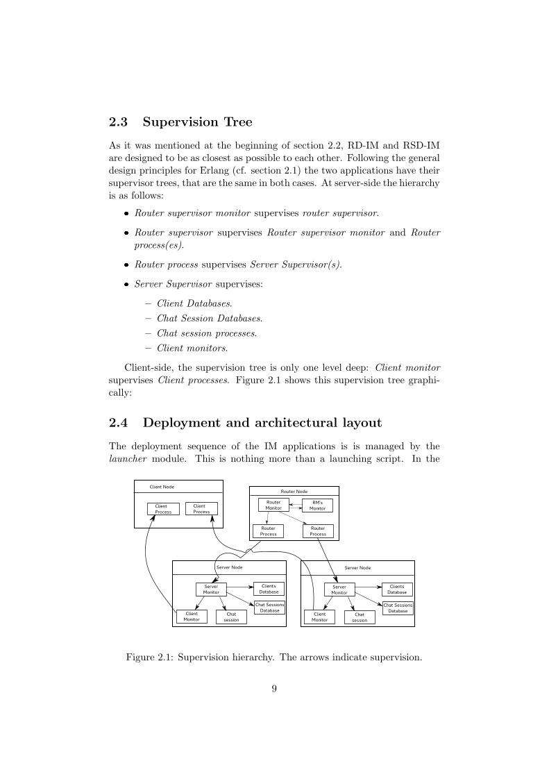
Client-side, the supervision tree is only one level deep: Client monitorsupervises Client processes. Figure 2.1 shows this supervision tree graphi-cally:
2.4 Deployment and architectural layout
The deployment sequence of the IM applications is is managed by thelauncher module. This is nothing more than a launching script. In the
Figure 2.1: Supervision hierarchy. The arrows indicate supervision.
9

case of the RSD-IM, the creation of the s groups and the assignment of thenodes to these is done at deployment stage.
Thus, the launcher module not only deploys the applications, but alsoshapes their architectures. For clarity purposes it is assumed that the ar-chitectures follow a tree topology. In reality, this is not necessarily true asin the case of the RD-IM the nodes form a complete graph, and for theRSD-IM nodes inside the s groups, they are also complete graphs.
Deployment follows an strict sequence determined by the supervisiontree. This is logical as those processes with supervision responsibilities are incharge of spawning their children processes. Hence, unless explicitly stated,these steps are the same for RD-IM and RSD-IM:
1. launcher module determines the total number of router processes andthe server supervisor processes that are children of each of these routerprocesses. Then it creates the router group s group (RSD-IM only)
2. For each router node in the architecture, launcher
� adds the node to the router group s group (RSD-IM only),
� creates a server group s group and adds the router and all chil-dren server nodes to it (RSD-IM only),
� spawns one router supervisor.
3. This router supervisor
� spawns its own monitor,
� spawns the relay processes (RSD-IM only)
� spawns its children router processes.
4. Each router process then determines its server supervisor children pro-cesses, and spawns them sequentially.
5. Finally, each server supervisor spawns the corresponding DB pro-cesses.
When all the server-side processes are launched, the module spawns therouters DB processes in the client nodes (cf. section 2.2.2).
Figures 2.2 and 2.3 depict the resulting architectures after the deploy-ment of the applications. These figures also show the simplification of thearchitecture introduced by SD-Erlang. RD-IM uses the default distributionmodel provided with Erlang: all the connections between server-side (i.e.,server and router) nodes are transitive. In the case of SD-Erlang, thesetransitive connections are established only inside the s groups. In both ap-plications, client nodes connections are established as hidden.
10

Figure 2.2: Connections in RD-IM architecture (client connections notshown).
Figure 2.3: Connections in RSD-IM architecture (client nodes notincluded).
11

2.5 Auxiliary Non-IM modules used for testingpurposes
It is worth of mention two modules that are used to test reliability and torecord the measurements of the benchmarks: the rhesus module and thelogger module.
Rhesus Module. Erlang approaches the error handling according to the”let it crash” principle. Applications are written in two parts: one thatperforms the operations required to solve the problem, and a second thatcorrects errors as soon as they arise. This strategy brings several advantagessuch as (i) lesser defensive code, (ii) focusing on the recovery of the systemrather than preventing the errors, or (iii) better diagnosis of the failures.
One of the assumptions made after this ”let it crash” principle is thatapplications must be able to provide (at least some) functionality under afailure scenario. It was in order to test whether this assumption held fortheir Amazon Web Services, that the engineers at Netflix developed the toolChaos Monkey (Bennett and Tseitlin, 2012): ¡¡Chaos Monkey is a servicewhich runs in the Amazon Web Services (AWS) that seeks out Auto ScalingGroups (ASGs) and terminates instances (virtual machines) per group¿¿(ıbid.).
Chaos Monkey is a tool of great interest within the context of the RD-IMapplication for obvious reasons. However, the Netflix version does not quitefit the requirements as it is node-focused.
There is an alternative implementation of this tool credited to DanielLuna2 that is more pertinent to the IM. Luna’s Chaos Monkey differs fromthe original in that (i) it is written in Erlang/OTP instead of Java, and (ii) itterminates instances of processes rather than instances of virtual machines(nodes). Unfortunately, as the RD-IM application is not using standardOTP behaviours, this version of the tool turned out to be incompatible.
For this reason, it was decided to build a custom-made module thatshows a similar behaviour to Chaos Monkey. This module, named Rhesusafter the rhesus macaque, has the following features:
� Random termination time for a process ranging from five seconds toone hour.
� User-defined termination time for a process.
� Weighted termination probability of router/server processes.
� Weighted termination probability of the server processes.2https://github.com/dLuna/chaos monkey
12
The basic principle behind this chaos generation scheme is quite simple.Rhesus looks for a router supervisorprocess and injects termination messages into the architecture. The time
rate at which these messages are sent is either randomly picked at the veryfirst cycle of its execution, or is passed as a parameter at the call of thefunction chaos on/1.
The sequence of steps that rhesus follows to terminate a process is rathersimple:
1. Rhesus chooses to finish either a server process or a router process.This pick is random, yet the probabilities are 1:4 that a router processis chosen (hence, 3:4 for the server processes).
2. It sends the appropriate message to the router supervisor process.
3. If the router supervisor receives the instruction to terminate a routerprocess, it executes an exit/2 passing as the argument the pid ofa selected router process (either router process, router supervisor pro-cess, or router supervisor monitor process). The probabilities are, inthis case, 1:number of router processes + 2.
4. If the router supervisor receives the order of terminating a server pro-cess, then it forwards the request to a router process as if it were a login request, for example.
5. The router process takes an aleatory pid of a server, and sends thetermination request to be processed.
6. When the process termination request arrives, the server supervisorprocess deals the issue in a similar way to how the router supervisordoes. In this case the probabilities are 1:5 for monitored processes DB,Chat DB, Clients DB, and server supervisor processes, and 1:10 forclient monitor and chat session processes.
This chaos generation logic exploits the fact that there are data struc-tures that store the pids of the IM processes running on each node. Thismakes the implementation fairly straight forward, making unnecessary torefactor the whole application using OTP behaviours. Besides, the rhesusmodule offers an additional advantage compared to Luna’s application: itsets a priori probabilities for the termination of the processes.
The Erlang/OTP Chaos Monkey does not make any distinction amongstthe different types of process that conform the application. In practicalterms this means that all the processes have the same chances to be termi-nated. Since the most frequent processes in the IM are client monitors andchat sessions. If all the processes have the same probability of being finished,it would be very unlikely to find an scenario in which the elected process
13

to stop is not one of those two. Or, similarly, it would be necessary to runextraordinarily long experimental series to make sure that other processesthan client monitors and chat sessions are stopped. And this is somethingnot convenient for the present case.
Logger Module. This module provides a measurements-gathering facil-ity, that is useful to study the performance of the IM applications in termsof latency and throughput.
The module provide a set of recorder functions that are spawned atthe client nodes whenever data-collection is required. At launch time, theycreate a comma separated value (.csv) file to which they write the latency orthroughput data in real-time. When the data collection session has finished,they just close the file and if there are no more sessions left they terminate.
Recorders can be customised, allowing to specify the name and path ofthe output files, the number of series to be recorded, and the length of thedata collection sessions. For throughput measurements, they also allow toset a threshold in latency that can be used to determine the quality of theservice (defined as percentage of messages delivered below threshold).
2.6 Summary
This chapter reviews the implementation, hierarchy and architecture of theinstant messenger applications. The design of the application follows thesupervision tree principle imposed by the Erlang standards for reliable ap-plications. Even though behaviours have not been used, process monitoringis performed.
The supervision tree imposes a hierarchy to both nodes and processes.It also guides the deployment sequence of the applications.
On the other hand, the resulting architectures after deployment are of avery different complexity. This is the result of the application of SD-Erlangtechnology.
Finally, two auxiliary modules have been described. Yet they do notbelong to the IM applications themselves, they play a crucial role in project:they provide the means for data-collection and reliability testing.
14

Chapter 3
Reliability Mechanisms andMessage Flow
This appendix includes the sequence diagrams that model the normal oper-ation of the instant messengers, as well as the reliability mechanisms. Thesewere used as a guide for the implementation.
3.1 D-Erlang Instant Messenger
The reliability of the system is achieved by the implementation of a seriesof monitoring processes called supervisors. In the case of the D-Erlangarchitecture there are (at least) two of these supervisor processes: (at least)one at router node and (at least) another one at server node.
There are several situations in which the system can behave in an unde-sirable manner, mostly due to bad calls, or processes that finish for reasonsother than a normal exit call sent to a process to finish. In these cases, thesupervisors must recover the system, taking it again to a valid state. Someof these misbehaviours of the system and how the supervisors tackle themare detailed below.
3.1.1 Handling Exceptions
A client tries to log in to the system when it is logged in already
1. Router process forwards the request to server supervisor.
2. server supervisor then spawns a new client monitor process.
3. This new client monitor queries the Client DB to check that the clientis not already registered in the system.
4. Client DB then sends a message to the new client monitor informingthat the client is already logged in.
15

Figure 3.1: Illegal login sequence diagram.
Figure 3.2: Illegal chat session sequence diagram.
5. Finally, the newly created client monitor notifies the client and server supervisor,and terminates.
A client tries to establish a chat session with another client towhom it already has an opened chat session
1. server supervisor process spawns a new chat session process.
2. This newly created chat session queries the Chat Session DB to ensurethat it does not exist already.
3. The Chat Session DB sends a message to the new chat session processindicating that it exists already.
4. The new chat session process then notifies the error to both: the clientwho requested the chat session, and the server supervisor, and termi-nates.
16

Figure 3.3: Chat session recovery from crash sequence diagram.
chat session process crashes before the session is finished
1. A system error message {error, Reason} is sent to server supervisor.
2. As soon as server supervisor traps this message, it works out whatclients were involved in this faulty chat session. A query to Chat Session DBincluding the Pid of the faulty process trapped in the message shouldbe enough to do so.
3. Next, it deletes this crashed session from the Chat Session DB.
4. Finally, the Server Supervisor spawns a new Chat Session process us-ing the information gathered, and
5. notifies the clients the Pid of the new chat session process.
server supervisor process crashes
1. router supervisor receives a system error message {error, Reason},and as soon as this error is trapped,
2. the router supervisor spawns a new server supervisor process.
3. The new server supervisor requests the active sessions and clients tothe Chat Session DB and Clients DB.
4. As soon as the new server supervisor collects the information aboutthe pertinent clients and sessions, it starts monitoring the appropriateclient monitor and chat session processes.
17

Figure 3.4: Server supervisor recovery sequence diagram.
Figure 3.5: Databases recovery sequence diagram.
Chat Session DB or Client DB fails In this case, the courses of ac-tion are the same for both, thus we will just indicate DB to refer eitherChat Session DB or Client DB.
1. System sends a an error message to the server supervisor.
2. The supervisor traps this error and spawns a new DB process.
3. Once the DB is started, it fetches the data from a replica, to get intothe same state as it was before it crashed.
3.1.2 Normal Behaviour
On the other hand, during the normal execution of the system there is alsoa constant flow of messages that characterises the behaviour of the instantmessenger:
18

Figure 3.6: Login sequence diagram.
Client login
1. Client sends a login request message to router process.
2. router process selects a server node and forwards the request to thecorresponding server supervisor process.
3. This server supervisor spawns a client monitor, and
4. this client monitor queries the Client DB to find out whether theclient is already logged in or not.
5. If the client is not logged in yet, then Client DB informs the client monitorthat the client is not logged in. Then client monitor registers the clientin the Clients DB, and
6. notifies the client that login has been successful.
Chat session
1. Client 1 sends a start chat session message to router process,who
2. forwards the request to the server supervisor ;
3. this supervisor then spawns a chat session process.
4. The created chat session process queries the Chat Sessions DB to en-sure that it does not exist already.
5. In normal circumstances, Chat Sessions DB answers that the sessiondoes not exist, and
6. chat session process, informs the involved clients the success of theoperation.
19

Figure 3.7: Chat session sequence diagram.
7. Once the chat session is established, the clients send messages to eachother.
8. To finish a chat session, one of the clients sends a finish chat sessionmessage to the chat session process.
9. chat session removes the chat session from the Chat Sessions DB, andright after that
10. it notifies the clients.
11. Finally, chat session process sends a {exit, session finished}message to the server supervisor, and terminates.
Client logout
1. Client sends a logout request message to its client monitor process.
2. When client monitor traps the request, it deletes the client from theClient DB,
3. and notifies the client that logout has been successful.
4. Finally, client monitor terminates.
In this case, the client has not active chat sessions when it logs out.However, if the client crashes or logs out while chatting, the sequence ofevents is slightly different. In this case,
20

Figure 3.8: Logout sequence diagram.
Figure 3.9: Logout sequence diagram.
1. the client monitor receives either a logout request or an {error,Reason} message. In both cases
2. client monitor unregisters the client from the Client DB.
3. Right after the client is removed from the database, the client monitorsends a finish chat session request to the chat session process,which would finish the session in a normal way.
4. Finally, the client monitor traverses all the entries in the Chat Session DBto discover all the sessions the client was involved, and finish themsendind the corresponding finish chat session message (cf. chatsession description).
3.2 SD-Erlang Instant Messenger
As in the case of the D-Erlang instant messenger system (cf. Section 3.1), theSD-Erlang version of the system has also different mechanisms to ensure the
21

Figure 3.10: Illegal login sequence diagram.
reliability of the system. This reliability is achieved, as in the previous case,implementing monitoring processes called supervisors. The SD-Erlangarchitecture contains (at least) three of these supervisor processes: (at least)one at router node, a second one (at least) at subrouter node, and (at least)another one at server node.
The following paragraphs describe different situations in which the nor-mal operation of the system is compromised, and the ways the system re-covers from this abnormal behaviour:
1. A client tries to log in to the system when it is logged in already.
(a) Router process forwards the request to subrouter process.(b) The subrouter process then forwards the request to the server supervisor,(c) and this server supervisor spawns a new client monitor process.(d) This new client monitor queries the Client DB to check that the
client is not already registered in the system.(e) Client DB then sends a message to the new client monitor in-
forming that the client is already logged in.(f) Finally, the newly created client monitor notifies the client and
server supervisor, and terminates.
2. A client tries to establish a chat session with another client to whomit already has an opened chat session.
(a) server supervisor spawns a new chat session process.(b) This newly created chat session queries the Chat Session DB to
ensure that it does not exist already.(c) The Chat Session DB sends a message to the new chat session
process indicating that it exists already.(d) The new chat session process then notifies both: the client who
requested the chat session, and the server supervisor, and termi-nates.
22

Figure 3.11: Illegal chat session sequence diagram.
Figure 3.12: Chat session recovery from crash sequence diagram.
3. chat session process crashes before the session is finished.
(a) A system error message {error, Reason} is sent to the server supervisorprocess.
(b) As soon as this server supervisor traps the error message, it worksout what clients were involved in this faulty chat session. Aquery to Chat Session DB including the PID of the faulty processshould be enough to do so.
(c) Next, this crashed session is removed from the Chat Session DB.
(d) Finally, the Server Supervisor, spawns a new Chat Session pro-cess with the information gathered, and
(e) notify the clients the new Pid of the chat session process.
4. router process crashes
(a) router supervisor traps the error message {error, Reason},and
(b) query the supervisor DB, the Supervisor DB to fetch the Pid ofthe process supervised by the failed router process.
(c) Finally, the router supervisor spawns a new router process, and
23

Figure 3.13: Router process recovery sequence diagram.
Figure 3.14: Subrouter supervisor process recovery sequence diagram.
(d) this new spawned process is linked to the subrouter process thatwas supervised by the failed process.
5. subrouter supervisor process crashes
(a) router process receives an {error, Reason} message from thefailed subrouter supervisor.
(b) As soon as this error message is trapped, the router process queriesthe supervisor DB, to retrieve the Pid of the subrouter supervisorprocess monitored by the failed subrouter supervisor.
(c) As in the previous case, a new subrouter supervisor is spawned,and
(d) linked to the subrouter process that was supervised by the failedprocess.
6. subrouter process crashes
In this case, the recovery logic is much the same as when a router processcrashes:
24

Figure 3.15: Subrouter process recovery sequence diagram.
(a) subrouter supervisor traps the error message {error, Reason},and
(b) query the supervisor DB, the Supervisor DB to fetch the Pid ofthe process supervised by the failed subrouter process.
(c) Again, the subrouter supervisor spawns a new subrouter process,and
(d) this new spawned process is linked to the server supervisor thatwas supervised by the failed process.
7. server supervisor process crashes
(a) subrouter process receives a system error message {error, Reason},and as soon as this error is trapped, the subrouter process
(b) spawns a new server supervisor process.
(c) the new server supervisor requests the active sessions and theclients to the Chat Session DB and Clients DB.
(d) As the new server supervisor collects the clients and sessions, itstarts monitoring the corresponding client monitor and chat sessionprocesses.
8. Chat Session DB or Client DB fails. In this case, the courses of actionare the same for both, thus we will just indicate DB to refer eitherChat Session DB or Client DB. This schema is also applied to theSupervisor DB data structures metioned in cases 4, 5, and 6. Wewill not describe the case to not overload the reader with redundantinformation.
(a) System sends a an error message to the server supervisor.
(b) The supervisor traps this error and spawns a new DB process.
25

Figure 3.16: Server supervisor recovery sequence diagram.
Figure 3.17: Databases recovery sequence diagram.
(c) Once the DB is started, it fetches the data from a replica, to getinto the same state as it was before it crashed.
On the other hand, during the normal execution of the system thereis also constant a flow of messages that characterises the behaviour of theinstant messenger:
1. Client login.
(a) Client sends a log-in request message to router process.
(b) The router process forwards this message to a subrouter processthat
(c) forwards the request to the corresponding server supervisor pro-cess.
(d) This server supervisor spawns a client monitor, and
(e) this client monitor queries the Client DB to find out whether theclient is logged in or not.
26
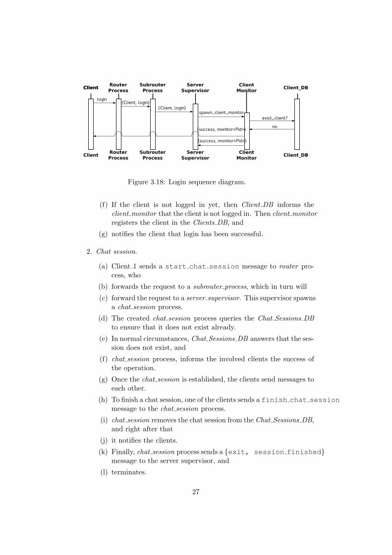
Figure 3.18: Login sequence diagram.
(f) If the client is not logged in yet, then Client DB informs theclient monitor that the client is not logged in. Then client monitorregisters the client in the Clients DB, and
(g) notifies the client that login has been successful.
2. Chat session.
(a) Client 1 sends a start chat session message to router pro-cess, who
(b) forwards the request to a subrouter process, which in turn will
(c) forward the request to a server supervisor. This supervisor spawnsa chat session process.
(d) The created chat session process queries the Chat Sessions DBto ensure that it does not exist already.
(e) In normal circumstances, Chat Sessions DB answers that the ses-sion does not exist, and
(f) chat session process, informs the involved clients the success ofthe operation.
(g) Once the chat session is established, the clients send messages toeach other.
(h) To finish a chat session, one of the clients sends a finish chat sessionmessage to the chat session process.
(i) chat session removes the chat session from the Chat Sessions DB,and right after that
(j) it notifies the clients.
(k) Finally, chat session process sends a {exit, session finished}message to the server supervisor, and
(l) terminates.
27
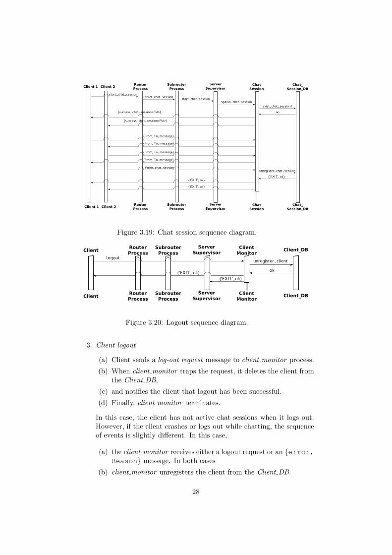
Figure 3.19: Chat session sequence diagram.
Figure 3.20: Logout sequence diagram.
3. Client logout
(a) Client sends a log-out request message to client monitor process.
(b) When client monitor traps the request, it deletes the client fromthe Client DB,
(c) and notifies the client that logout has been successful.
(d) Finally, client monitor terminates.
In this case, the client has not active chat sessions when it logs out.However, if the client crashes or logs out while chatting, the sequenceof events is slightly different. In this case,
(a) the client monitor receives either a logout request or an {error,Reason} message. In both cases
(b) client monitor unregisters the client from the Client DB.
28

Figure 3.21: Logout sequence diagram.
(c) Right after the client is removed from the database, the client monitorsends a finish chat session request to the chat session pro-cess, which would finish the session in a normal way.
(d) Finally, the client monitor traverses all the entries in the Chat Session DBto discover all the sessions the client was involved, and finish themsendind the corresponding finish chat session message (cf.chat session description).
29

Chapter 4
Changes to the OriginalDesign
The implementation of the system tries to fulfil the different behaviours de-scribed on the section 3.1 Reliability mechanisms and messages flow. How-ever, due to the constraints imposed by the language, and decisions takenat implementation time, the final system does not reproduce exactly theactions depicted on this document. This section enumerates such changes,while also offering some additional information.
1. A client tries to log in to the system when it is logged in already.
When a client, logs in to the system, it is also locally registered inthe node in which is executing. Hence, if the client tries to log inagain in that node, the first thing it does is to check whether there isa registered process in that node with the same name. If that is thecase, then the login action is aborted and an error message informs ofthis situation. If the client tries to log in from another node, then thesequence described in section 3.1 is executed.
2. A client tries to establish a chat session with another client to whomit already has an opened chat session.
The final implemented version does not make any explicit start session
calls to start a chat session. That is, the client does not have to per-form a chat session request before being able to send any messages toanother client.
Client processes keep track of the chat sessions they are participat-ing. Every time a client receives {Sender, Receiver, Message,
Send Message}, it tries to retrieve the pid of that chat session fromtheir internal opened sessions storage.
If there is not such chat session, the client sends a chat session requestto the server supervisor process. The server supervisor spawns the
30

chat session process, returns the pid to the client, and then the clientsends the message. If that session exists already, the client sends themessage to the corresponding chat session process. Therefore, thissituation cannot happen.
3. chat session process crashes before the session is finished
This is probably the situation where the original design differs the mostrespect to the final implementation. Due to the way in which the chatsessions are started (i.e., they do not have to be set up explicitly),there is no need of handling this error and recover the process: whenthe next message is sent, a new chat session will be spawned. For thatreason, the recovery strategy consists of behaving as if the chat sessionprocess finished normally.
4. server supervisor process crashes.
When the router process traps an abnormal termination of the server supervisor,it only knows the pid of this crashed process. Even though it is possibleto access the the client db and chat db processes –as they are globallyregistered processes– it was decided to keep a record of the monitoredprocesses by the server supervisor on a separate monitored db processto make the recovery sequence faster. This monitored db process issimilar to the other db processes, but it is registered locally inside theserver node.
The recovery strategy involves the spawning of a new server supervisorprocess, and the traversal of this monitored db, instead of traversingthe client and chat databases to retrieve the required information.In fact, this is actually the strategy proposed for the recovery of therouter process, subrouter supervisor and subrouter process processes inthe SD-Erlang version of the system (cf. section 3.2).
5. Chat Session DB or Client DB fails.
There was introduced an improvement, respect to the original strat-egy. If the crashed database is the main, during the recovery strat-egy, main and replica databases are swapped. The reason is that ifany other process needs to access the information stored while thedatabase is recovering, it is available since the swapping requires onlyone operation.
6. Client login
Changes at this level have been pointed out already. The originalproposal assumed two explicit operations:
(a) Start the client process.
(b) Execute the login.
31

The actual implementation only requires the second. When the userexecutes the function
client:login(atom()),
this function starts a client which self-logs in following the sequencedescribed in Figure 3.6.
7. router supervisor crashes.
The original reliability model did not contemplate this failure. Themost sensible way to tackle this situation is to make a ¡¡keep alive¿¿process. However, after facing several problems, a less efficient but sim-ilarly effective tactic was implemented. At launch time, router supervisorspawns and monitors a sister process, whose function is only to monitorthe router supervisor. This router supervisor monitor process keepsthe same information as the monitored process, at any time. Thuswhen the router supervisor finishes unexpectedly, the monitor processspawns a new process, feeding the information of the processes thatneed to be monitored.
When the router supervisor monitor crashes, the router supervisor spawnsa new one, feeding the information into the newly spawned process.
8. client process crashes.
Since the client side is not of the interest of this research, section3.1 does not include the case of the unexpected termination of clientprocesses. However, this circumstance also has effects at the serverside. In particular, it is necessary to terminate the chat sessions inwhich this crashed client is taking part, as well as remove the clientfrom the Clients DB. Thus, client monitor also traps these abnormaltermination of client processes behaving as if the client has logged outnormally.
9. SD-Erlang Router/Subrouter processes. The original design includeda layer of routers and then a second layer of slave routers that would bein charge of monitoring the servers. At the moment of the implemen-tation it was seen that the top layer of routers did not any advantagesand, potentially it could be a bottleneck. For this reasons, the finalimplementation lacks of this extra layer of routers.
32

Chapter 5
Evaluation
This chapter describes the results of the tests made on the instant messengerapplications.
5.1 Experimental Setup
All the measurements have been taken using the GPG cluster located atthe University of Glasgow School of Computing Sciences. This is a Beowulfcluster composed of 20 nodes, of which 17 are used. The reason is that thereare three nodes that can be used by any member of the school without priornotice, and this circumstance can contaminate the results obtained.
Each of the nodes in the cluster has the following configuration:
� 16 cores (2×Intel Xeon E5-2640 2 GHz).
� 64 GB RAM (4 GB RAM/core).
� 300 GB local disk.
� 10 Gb Ethernet interconnect
The software configuration of these nodes is as follows:
� Scientific Linux 6 (Carbon) 64-bit.
� Erlang/OTP 17.4 (modified by the RELEASE project), downloadedand built from the RELEASE Github repository.
5.2 Experiment 1: Impact of the Number of Serverswith No Failures
Design. In the first experiment we analyse whether there are differences inthroughput between the Distributed Erlang version of the instant messenger
33

Figure 5.1: D-IM vs SD-IM. Maximum throughput time series.
(D-IM) and the Scalable Distributed Erlang version of the instant messenger(SD-IM). For that we gradually increase the number of server nodes (3, 4,6, 8, 12, 16) while keeping the number of router nodes fixed – equal to one.The reliability is not considered in this experiment
This setup results identical architectures for both IM applications, sincethe SD-IM only has one s group. Hence, s group operations in the SD-IMare analogous to the global operations in the D-IM. Traffic is injected atsame rates in all conditions. Traffic generation is modelled after [XGT07].
Results. Figure 5.1 shows the evolution of the throughput for all the ar-chitectures considered, in time series of 15 minutes each. It can be observedthat it takes about six minutes for the throughput to become stable. Thiscan be due to the implementation of the traffic generation logic. Traffic isstarted by the traffic generators in a big initial burst. Despite the fact thatmessages are sent at random times between one and 20 seconds, during thefirst minutes messages may be overloading the queues of processes at theserver nodes (e.g., server supervisor or chat db processes). As chat sessionsare taking place, the traffic becomes more uniform and the size of thesequeues diminishes.
34

Figure 5.2: D-IM vs SD-IM. Maximum mean throughput whenapplications are stable.
Figure 5.1 also show the way the IM applications scale. Consideringthat the Y-axis show the number of messages per minute that go through thearchitecture, the first evident fact is that the differences between technologies(D-Erlang and SD-Erlang) are minimal, if any. More interesting, though isthe linear relationship between the number of messages per minute andthe number of server nodes present. This figure suggests that these servernodes have an effective capacity of handling approximately 106 messagesper minute. In fact, the mean values of the delivered messages when theapplications are stable seem to reinforce this ratio (Figure 5.2).
A closer inspection of Figure 5.2 shows that the number of messages thateach of these server nodes is able to handle decreases as the number of servernodes increases. Hence, in architectures up to eight server nodes, thesehandle slightly more than the already mentioned 106 messages. Conversely,in larger architectures the server nodes are able to handle slightly fewermessages than 106.
Considering the architectures tested altogether, an independent sam-ples test indicates that the mean throughput of the SD-IM (916,234 mes-sages/minute) is larger than the throughput of the D-IM (765,351 mes-
35

sages/minute; p <0.5). However, this result must be handled carefully.This same independent samples test applied to each of the different archi-tectures considered, shows that SD-IM has an statistically significant higherthroughput than D-IM only for those architectures comprised of four andsix server nodes. Since for the rest of the conditions throguhputs seem tobe the same, it is safer to assume that there are no performance differencesbetween the applications, and that these differences must be caused for someunspecific random factor.
5.3 Experiment 2: Impact of the Number of Servers& S groups with No Failures
Design. The second experiment analyses the differences in throughputbetween the D-IM and the SD-IM when the number of servers varies, butthe number of routers is kept constant. That is a 2×3 factorial design withfactors technology –namely, Distributed Erlang and Scalable DistributedErlang— and number of server nodes –with three levels: 6, 8, and 12.
The number of router nodes was fixed to two. This allows the creationof two s groups in the SD-IM that vary in size according to the numberof server nodes present in each of the experimental conditions. Therefore,the s groups in the case of the SD-IM were composed of one router andthree, four or six servers, depending on the level of the variable number ofserver nodes under test. As in the case of Experiment 1, reliability is notconsidered in this experiment.
Results. Figure 5.3 shows the evolution of the throughput in the differentconfigurations of the instant messenger architectures through a time series of15 minutes. As in the case of the previous experiment it takes approximately6 minutes for the applications to become stable. Once the applicationsreach stability, they show constant differences in throughput only in theexperiment with two router and eight server nodes architecture.
When the number of server nodes is set to eight, these differences arestatistically significant (p <0.05) although the throughput of SD-IM is onlya 2% higher than the throughput of D-IM. In turn, when the number ofservers is six and 12 these differences in throughput disappear (p >0.05).
These later results seem to indicate that the differences found in the caseof eight server nodes might be caused for some external factor such as thestate of the cluster when the tests were running. In this sense, Figure 5.4shows more clearly this peak in the throughput of SD-IM when the number ofserver nodes is eight. However, the overlapping of the mean throughputs inthe other two considered conditions, reinforce the idea that in the differencefound is due to an external factor.
36
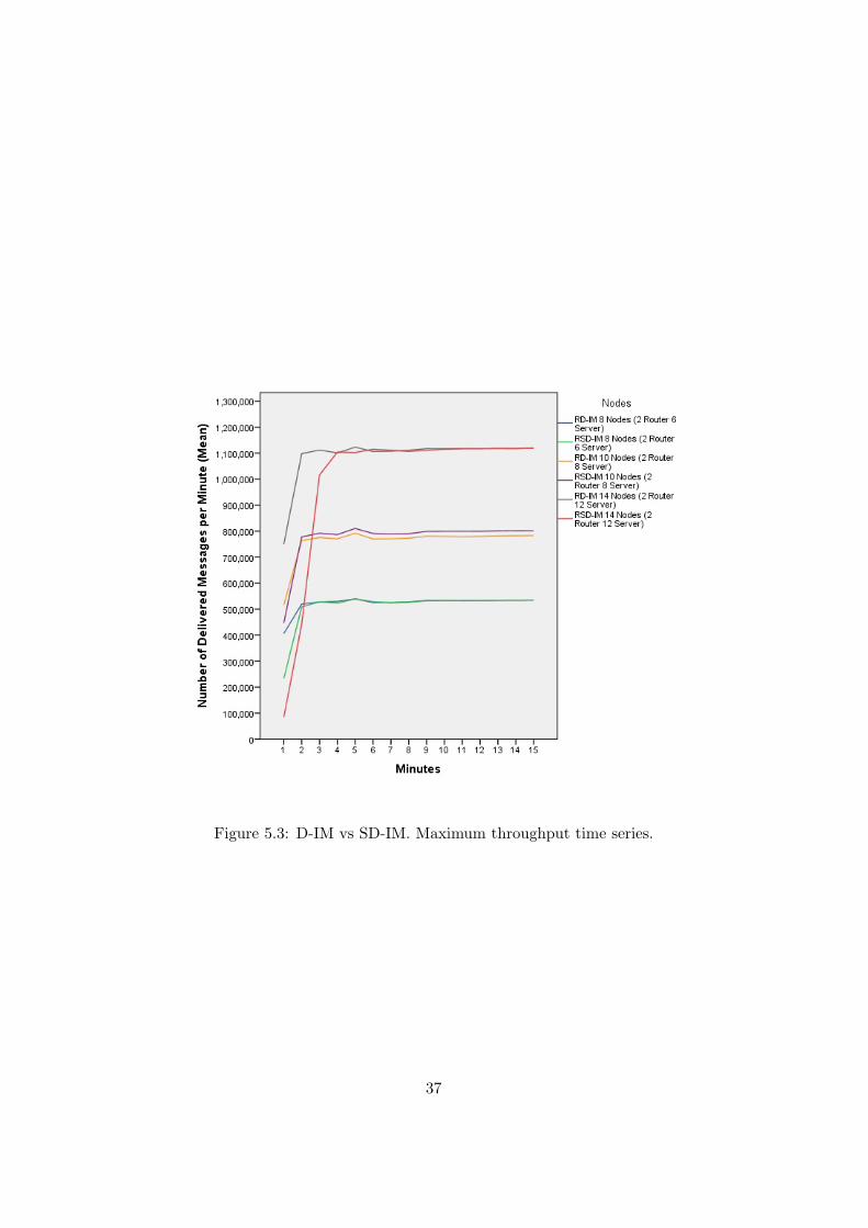
Figure 5.3: D-IM vs SD-IM. Maximum throughput time series.
37
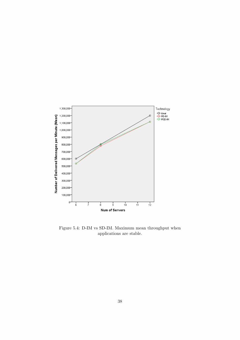
Figure 5.4: D-IM vs SD-IM. Maximum mean throughput whenapplications are stable.
38

This is not the only effect observed. Figure 5.4 also shows the idealgrowth rate as the number of server nodes scale. Figure 5.2 shows that inthe case of six and eight servers, the throughput of both D-IM and SD-IMare above this ideal. However, the introduction of one more router nodeseems to impact the maximum throughput of the applications, according tothe throughput rates described by Figure 5.4.
This is clear in the case of both D-IM and SD-IM, where the throughputis below the ideal for all the considered conditions. In this sense, Experiment1 showed that in the case of architectures with one router and 12 servernodes throughput was below the ideal as well. However, when a secondrouter node is introduced, the observed throughput for both applications isnot only below the ideal, but also lower than the case of only one routerarchitectures (cf. Figure 5.2).
5.4 Experiment 3: Impact of the Number of S groupswith No Failures
Design. This third experiment intends to determine the differences inthroughput between the D-IM and the SD-IM when the number of routersvaries, but the number of servers is kept constant. As in the case of theExperiment 2 this is a 2×2 factorial design with factors technology –namely,Distributed Erlang and Scalable Distributed Erlang— and number of routernodes –with four levels: 1, 2, 3, and 4.
The number of server nodes was fixed to 12. This allows the creation ofdiffferent number of s groups in the SD-IM that vary in size according to thenumber of router nodes present in each of the experimental conditions. Thisway, the s groups in the case of the SD-IM were composed of one router and3, 4, 6, or 12 servers, depending on the level of the variable number of routernodes under test. As in the case of the previous experiments, reliability isnot considered in this experiment.
Results. Figure 5.5 shows the evolution of the throughput, in a 15 minuteslong time series, for the different architectures considered. As in the previouscases the throughput becomes stable after 6 minutes.
The results obtained in this experiment seem to confirm the existenceof an effect of the number of routers and the number of s groups in thethroughput of the IM applications. Figure 5.5 and Figure 5.6 show that thehighest throughput correspond to the IMs that only have one router. As thenumber of routers increase, the throughput decrease. Yet this decline is dif-ferent attending to the type of technology involved. This way, the differencein the throughput between a D-IM architecture composed of one router and12 servers, and another composed of two routers and 12 servers is roughly a6%, and statistically significant (p <0.05). However, the differences between
39

Figure 5.5: D-IM vs SD-IM. Maximum throughput time series.
40

Figure 5.6: D-IM vs SD-IM. Maximum mean throughput whenapplications are stable.
the two routers architecture and the subsequent three and four routers archi-tectures are minimal and non-significant (p >0.05). In fact, Figure 5.6 showhow D-IM throughput remains constant as the number of routers grows.
This routers effect is more evident in the case of the SD-IM. Indeed, inthis case the addition of a new router node causes a statistically significantreduction of the throughput (p <0.05). In case of the 4 router architecturethis difference is around a 12% respect to the 1 router architecture.
Figure 5.6 also suggests that the introduction of new s groups penalisethe throughput of the IM application. When a second router node is in-troduced, the reduction in the throughput of D-IM and SD-IM is similar(p >0.05). However, the more routers are introduced, the greater the dif-ferences in their throughputs (p <0.05 for both three and four routers). Ifthere were no effect of the number of s groups these differences should remainconstant and non-significant. Moreover, since the differences in throughputbetween SD-IM three routers and SD-IM four routers (which implies thepresence of three and four s groups respectively) are significant as well (p<0.05), seems clear that the number of s groups has an additional impactin the performance of the IM application.
41

5.5 Experiment 4: Impact of Failures
Design. In the Experiment 4 we analyse fault-tolerance of the IM appli-cations. We compare two conditions: control, in which the system runsfree of failures for 15 minutes, and treatment, in which different random IMprocesses are terminated at an interval of 15 seconds (i.e., fault rate is 240failures per hour). Faults were introduced after five minutes of the start ofthe experimental trials, once the applications are stable. This means thatin the case of the experimental conditions, failures were present only fromminute 5 to minute 15. Again there are two levels of the technology variable,namely, D-Erlang and SD-Erlang.
The architecture used for this experiment consisted of two router nodesand 12 server nodes, making 14 nodes in total. In the case of the RSD-IM(R meaning reliable) this generates an architecture with three s groups: onerouter s group and two server s groups. This architecture is kept constantfor the whole experiment.
Again the dependent variable is throughput, measured as the numberof delivered messages in one minute. The traffic load is the maximum sup-ported for these architectures, as determined in Experiment 3.
Results. Figure 5.7 shows the evolution of the throughput during thewhole experiment, in the presence and absence of failures, for both RD-IMand RSD-IM applications.
The results show that SD-Erlang can be used to build reliable applica-tions in the same fashion as D-Erlang. Moreover, the use of s groups donot impose any special restriction to the default reliability mechanisms withwhich Erlang/OTP is shipped. Recall that the RSD-IM is just a refactoredversion of the RD-IM, which introduces the minimum necessary changes re-quired to use the s groups functionality. Apart from this, no further changeswere made – especially regarding the supervision trees and fault-tolerancemechanisms.
Thus, two important considerations can be extracted: firstly, it is pos-sible to build fault-tolerant applications using SD-Erlang in the same wayas with D-Erlang. Secondly, s groups neither impose additional costs, norrequire additional mechanisms to support fault tolerance. These assertionsare backed by Figures 5.8 - 5.10.
Figure 5.8 shows a summary of the mean throughputs for all the con-ditions. As it can be seen, they all are practically identical. In fact, two-samples means tests show that there are not statistically significant differ-ences in throughput between RD-IM and RSD-IM (p >0.05; cf. Figure 5.9)as well as between the presence and absence of faults (p>0.05; cf. Figure5.10) when the fault rate is 240 faults per hour.
42

Figure 5.7: RD-IM vs RSD-IM. Throughput time series in absence andpresence of faults.
43

Figure 5.8: RD-IM vs RSD-IM. Mean trhoughput in absence and presenceof failures.
44

Figure 5.9: RD-IM vs RSD-IM. Mean throughput in absence and presenceof faults (intra-technology).
45

Figure 5.10: RD-IM vs RSD-IM. Mean throughput in absence andpresence of faults (inter-technology).
46
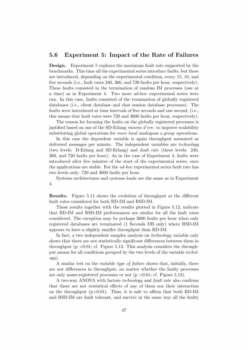
5.6 Experiment 5: Impact of the Rate of Failures
Design. Experiment 5 explores the maximum fault rate supported by thebenchmarks. This time all the experimental series introduce faults, but theseare introduced, depending on the experimental condition, every 15, 10, andfive seconds (i.e., fault rates 240, 360, and 720 faults per hour, respectively).These faults consisted in the termination of random IM processes (one ata time) as in Experiment 4. Two more ad-hoc experimental series wererun. In this case, faults consisted of the termination of globally registereddatabases (i.e., client database and chat session database processes). Thefaults were introduced at time intervals of five seconds and one second, (i.e.,this means that fault rates were 720 and 3600 faults per hour, respectively).
The reason for focusing the faults on the globally registered processes isjustified based on one of the SD-Erlang raisons d’ere: to improve scalabilitysubstituting global operations for more local analogous s group operations.
In this case the dependent variable is again throughput measured asdelivered messages per minute. The independent variables are technology(two levels: D-Erlang and SD-Erlang) and fault rate (three levels: 240,360, and 720 faults per hour). As in the case of Experiment 4, faults wereintroduced after five minutes of the start of the experimental series, oncethe applications are stable. For the ad-hoc experimental series fault rate hastwo levels only: 720 and 3600 faults per hour.
Systems architectures and systems loads are the same as in Experiment4.
Results. Figure 5.11 shows the evolution of throughput at the differentfault rates considered for both RD-IM and RSD-IM.
These results together with the results plotted in Figure 5.12, indicatethat RD-IM and RSD-IM performances are similar for all the fault ratesconsidered. The exception may be perhaps 3600 faults per hour when onlyregistered databases are terminated (1 Seconds DB only) where RSD-IMappears to have a slightly smaller throughput than RD-IM.
In fact, a two independent samples analysis on technology variable onlyshows that there are not statistically significant differences between them inthroughput (p >0.01; cf. Figure 5.13. This analysis considers the through-put means for all conditions grouped by the two levels of the variable techol-ogy).
A similar test on the variable type of failure shows that, initially, thereare not differences in throughput, no matter whether the faulty processesare only name-registered processes or not (p >0.01; cf. Figure 5.13).
A two-way ANOVA with factors technology and fault rate also confirmsthat there are not statistical effects of any of them nor their interactionon the throughput (p>0.01). Thus, it is safe to affirm that both RD-IMand RSD-IM are fault tolerant, and survive in the same way all the faulty
47
Figure 5.11: RD-IM vs RSD-IM. Throughput time series at different faultrates.
48

Figure 5.12: RD-IM vs RSD-IM. Mean trhoughput in absence andpresence of failures.
49

Figure 5.13: RD-IM vs RSD-IM. Mean throughput in when faultyprocesses are any IM process and registered databases only.
conditions considered. These results together with the results of Experi-ment 4 also indicate that RD-IM and RSD-IM do not get any penalty inperformance when fault rates are as high as 3600 faults per hour.
It was mentioned earlier that RSD-IM seemed to have a slightly smallerthroughtput when the fault rate was 3600 faults per hour and the faultyprocesses were the registered databases only. Figure5.13 shows also a verytiny step when only these faulty processes are considered (columns on theright). This seems to suggest that even though RSD-IM is fault tolerant, itsperformance in terms of throughput is worse than the RD-IM performance.
To explore this circumstance further, two additional Mann-Whitney non-parametric tests were carried out: one to check whether there are differencesbetween RD-IM and RSD-IM when the fault rate is 720 faults per hour, andthe other to make the same check when the fault rate is 3600 faults per hour.None of them were statistically significant (p >0.01). Hence, the differenceshown in the graph must be due to the size of the sample (N = 10 for eachof the four conditions).
50

Chapter 6
Conclusion and Future Work
In this report we present design and evaluation of two versions of an IMapplication. The first version (D-IM) is implemented in distributed Erlang.The second version (SD-IM) is a result of refactoring of D-IM with minimalrequired changes. While the purpose of the IM application is two benchmarkdistributed Erlang and SD Erlang, the design complies with all main prin-ciples of an IM application. The traffic generator was also built to closelymimic human interaction in an IM application (Section 2).
This is also the first benchmark where we evaluate impact of failuresin distributed and SD Erlang applications. The results show that on asmall scale (up to 12 nodes) RD-IM and SD-IM behave identically, and SDErlang applications require no additional reliability mechanisms. Thus, thebenchmarks behave identically event when killing one globally registereddatabase per second over a 15 minute period (Figure 5.11).
51

Bibliography
[Arm07a] Joe Armstrong. A history of Erlang. In Proceedings of the ThirdACM SIGPLAN Conference on History of Programming Lan-guages, HOPL III, pages 6–1–6–26, New York, NY, USA, 2007.ACM.
[Arm07b] Joe Armstrong. What’s all this fuss about Erlang?, 2007.
[AVW92] J. L. Armstrong, S.R. Virding, and M. C. Williams. Use of pro-log for developing a new programming language. In Proceedingsof the First Conference on the Practical Application of Prolog.Association for Logic Programming, 1992.
[CLG+15] Natalia Chechina, Huiqing Li, Amir Ghaffari, Simon Thompson,and Phil Trinder. Improving network scalability of Erlang. 2015.
[CLTG14] N. Chechina, H. Li, P. Trinder, and A. Ghaffari. Scalable SDErlang computation model. Technical Report TR-2014-003, TheUniversity of Glasgow, December 2014.
[CT09] Francesco Cesarini and Simon Thompson. ERLANG Program-ming. O’Reilly Media, Inc., 1st edition, 2009.
[CVss] Francesco Cesarini and Steve Vinoski. Designing for scalabilitywith Erlang/OTP. implementing robust, fault-tolerant systems.In press.
[XGT07] Zhen Xiao, Lei Guo, and John Tracey. Understanding instantmessaging traffic characteristics. In Distributed Computing Sys-tems, 2007. ICDCS’07. 27th International Conference on, pages51–51. IEEE, 2007.
52