a report on electrical fishing for razor clams (ensis sp.) and
TRANSCRIPT


Not to be quoted without prior reference to the authors © Crown Copyright 2011
Marine Scotland Science Report 03/11
A REPORT ON ELECTRICAL FISHING FOR RAZOR CLAMS (ENSIS SP.) AND ITS LIKELY EFFECTS ON THE MARINE ENVIRONMENT
Mike Breen, Trevor Howell and Phil Copland
February 2011
Marine Scotland Science Marine Laboratory 375 Victoria Road Aberdeen AB11 9DB

1
A REPORT ON ELECTRICAL FISHING FOR RAZOR CLAMS (ENSIS SP.) AND ITS LIKELY EFFECTS ON THE MARINE ENVIRONMENT Mike Breen, Trevor Howell and Phil Copland Marine Scotland – Science, 375 Victoria Road, Aberdeen Executive Summary This report summarises information relevant to electrical fishing for razor clams (Ensis sp.) in Scottish inshore waters and considers how the effects of this fishing method on the target species and the wider marine environment should be evaluated. It also highlights health and safety concerns associated with the fishing method and makes recommendations related to the management of any future fishery. The information in the report has been assembled from scientific publications, “grey” literature and anecdotal sources and is presented in five sections: 1. Biology and management of the Ensis. sp. stocks in Scotland; 2. Principles of marine electrical fishing; 3. Effects of electrical fishing on marine organisms and habitats; 4. Health and safety implications of electrical fishing operations; and 5. Future research requirements to assess the effects of electrical fishing for Ensis on
the marine environment These sections are summarised below: 1. Biology and Management of the Ensis. sp. Stocks in Scotland Of the six UK species of marine bivalve molluscs colloquially referred to as razor clams, two are of commercial importance in Scotland. These are the Pod Razor, Ensis siliqua (L, 1758), and the more common Curved Razor, Ensis arcuatus (Jeffreys, 1865). Both are widely distributed around the coast of Scotland and can be found in dense beds in areas with some shelter from wave action. Although both species are normally found from the lower shore down to about 20 m they have different habitat preferences with E. siliqua generally found in fine sands and muddy sediments while E. arcuatus prefers more coarse-grained sediments. Ensis are filter feeders and normally lie vertically in the sediment with two small siphons, through which they feed, visible on the sediment surface. Although they are capable of burrowing rapidly when disturbed they are not confined to permanent burrows and relocate by crawling over the sediment or swimming. In Scotland both species can live in excess of 20 years but E. siliqua is longer lived and grows to a larger maximum size, while E. arcuatus has more variable growth rates. Growth also varies in different locations and there is evidence that in some areas male E. siliqua grow at a faster rate and to a larger maximum size than females from the same area. The

2
sexes are separate in both species and spawning generally takes place during the spring or summer. The larvae are thought to have a pelagic phase lasting about a month prior to settlement. Studies in Scotland indicate that a substantial proportion of both species, but particularly E. siliqua, reach sexual maturity at sizes above 100 mm. The commercial razor clam fishery in Scotland emerged during the mid 1990s with reported landings ranging between 40 – 220 tonnes until 2006, but then rose sharply to reach 718 tonnes in 2009 with a value of £1,754,000. Since 1997 between 14 and 27 vessels a year have been involved in the fishery. These are mainly small vessels (<10 m), with hand caught methods (mainly divers) dominating the fishery. The sharp rise in landings since 2006 is thought to be related to the increasing use of illegal electrical fishing methods. There is presently no limit on catch or effort in the Scottish razor clam fishery. In Scotland current management measures relating to Ensis are: the EU minimum landing size (MLS) of 100 mm; some spatial restrictions on the use of mobile gears; and the requirement for all commercial fishing vessels to report weight landed and the ICES statistical rectangle where fishing took place. In response to the increase in illegal electrical fishing, changes to the vessel fishing licence relating to the carriage of electrical equipment were introduced in 2010. Concern over the sustainability of the fishery has been prompted by the marked increase in landings allied to the use of electrical fishing methods. Because electrical fishing is illegal, reliable information on the impact of the method on target and non-target species, on gear selectivity and incidental mortality is scarce. The illegal component of the fishery compounds the problem of obtaining accurate fisheries data required to manage the fishery. Since the expansion of the fishery, there have been no stock assessments of Ensis or surveys to provide information on population dynamics, distribution of stocks and patterns of recruitment. Relative to other commercially important bivalves Ensis are long-lived, slow-growing, and attain sexual maturity late in life. Scottish studies indicate that substantial, but different, proportions of the two commercially exploited species reach sexual maturity above the EU MLS of 100 mm. It is recommended that the effect on landings of recent initiatives to reduce illegal razor clam fishing activity should be closely monitored. Improved information on the state of the stocks is required. This would be provided by stock surveys in conjunction with more detailed log book information. Scottish Inshore Fisheries Groups (IFGs) could facilitate the collection of more detailed (log book) information. If landings continue to rise, precautionary measures to control harvesting may need to be introduced, until better information on the state of the stocks is available. Ideally, future harvesting should be based on stock surveys and removals should be regulated in a precautionary manner. It is also recommended that the MLS is increased so that Ensis are not harvested before they reach sexual maturity. A precautionary MLS of 130 mm is suggested.

3
2. Principles of Marine Electrical Fishing In simple terms, electrical fishing works by using electrical currents to produce a response in the target species, which either compromises the target’s ability to evade capture or makes it available for capture by stimulating it to move into the path of the fishing gear. The form and dimensions of the electric field generated in the water (and underlying substrate) and its effect on the target will be dependent upon many factors, including: the conductivity of the water (and substrate); the form (AC, DC and/or pulsing) and strength of the electrical output; the location, orientation and construction of the electrodes; and the target species itself, its biology/physiology, size, proximity and orientation within the electric field. Electrical Fishing for Ensis in Scotland Fishermen are thought to have been using electrical fishing techniques in the Scottish razor fishery since 2004, and possibly earlier (McKenzie, pers. comm.). Because the practice is illegal, there is insufficient information available to provide detailed descriptions of the gears typically used and electrical fields applied. Approximate descriptions and insights into past and current practices have been obtained as a result of discussions with various agencies, including Marine Scotland Compliance (MSC), the Health and Safety Executive (HSE) Diving Inspectorate and Strathclyde Police. A more in-depth study of these accounts and any confiscated equipment would provide a valuable insight into the technologies used in this illegal fishing technique. On the basis of information available, it appears that intense electrical fields, emitted by electrodes towed slowly across the seabed, stimulate Ensis to temporarily leave their burrows. They are then collected most commonly by a diver following the fishing vessel, or alternatively by a dredge drawn across the surface of the seabed. 3. Effects of Electrical Fishing on Marine Organisms and Habitats Based on the literature review, potentially detrimental effects associated with electrical fishing for Ensis, were identified as: • physical disruption and damage of benthic habitats due to fishing activities; • the release of pollutants (particularly metals, e.g. copper) from electrolysis at the
electrodes; and • effects of electrical fields on Ensis and non-target species, including fish and
epifauna and infaunal invertebrates). The physical effects from electrical fishing gears using divers are anticipated to be small, particularly in comparison to alternative fishing methods (e.g. hydraulic dredges). Direct comparison of electrical and other fishing methods, would require some level of quantification of the impact from electrical gears, which is not possible at this time. There is insufficient information about the fishing methods to estimate the magnitude of any release of metal ions; the fate or effects of polluting metals are beyond the scope of this

4
review. It is recommended that any future work should attempt to estimate release rates of copper and other metals as a result of electrical fishing and, if significant, consider the fate and effects of these pollutants. Possible effects of electricity on target and non-target species are considered in the report in more detail. For each, the known behavioural responses to electrical fields and the likely effects of that interaction, in terms of injuries and resulting mortality, are considered. Most studies focus on fish as they are the normal target group for electrical fishing. The most damaging forms of electrical current are AC and low frequency (<200Hz) pulsed (DC and AC) signals, while the least damaging is a smooth DC current. Injuries most commonly observed in fish include broken spines and internal bleeding. The main cause of fish mortality is from respiratory arrest, due to synaptic fatigue caused by overstimulation of the autonomic nervous system. Significant mortalities have also been observed in invertebrate species exposed to intense electrical fields, although the likely causes were unspecified. Short term direct effects of electrical fields on Ensis appear to be limited. This is inferred by the fact the catch is generally exported live and supported by observations that most Ensis specimens, if left on the sea bed, typically rebury themselves within ten minutes. However, any exposed individuals left on the sea bed (i.e. discarded) are at increased risk of predation. Electric fields, of the required intensity to catch Ensis, are thought to be sufficient to injure and kill fish and invertebrates that are within a few meters of the electrodes. The fished areas may be exposed to potentially high intensity electrical fields for relatively prolonged periods, typically between one and two minutes. This would suggest that this fishery could have a detrimental effect on non-target organisms at a local level. However, more information about electrical field strengths and form, as well as knowledge of the effects on exposed species, is needed before spatial limits can be defined with any degree of certainty. The geographical scale of any such effects will be determined by the distribution of Ensis. The capacity for recovery from and/or mitigation of any deleterious effects at a species and habitat level could not be reviewed due to the lack of available information, but would need to be determined in an appropriately designed impact study. 4. Health and Safety Implications of Electrical Fishing Operations Electric fishing for Ensis sp. is considerably more hazardous than traditional fishing techniques. In addition to the risks and hazards associated with fishing from small inshore boats, the most common technique involves diving and the use of high power electrical currents and is not regulated. Under these circumstances, the likelihood of serious injury or fatalities is considerably increased. Of particular concern is the clandestine and ad hoc approach to the development of the electrical fishing technology. Without sufficient expertise in marine electrical systems, poor design and maintenance of the equipment are likely to increase the risk of injury and fatalities still further.

10
main Scottish species, particularly E. arcuatus, can occur in dense beds, direct estimates of density are rare in the literature. In the Marine Laboratory Western Isles study (Anon 1998) visual estimates of density, based on clam siphons counted by divers, ranged from 2.2 – 15.0 individuals / m2 in an undisturbed area (1998). A more wide ranging study covering sites in the Clyde, the Highlands and the Western Isles reported densities in the range of 0.1 - 16 clams / m2 (0.3 - 40 clams / 2.5 m2 ; Muir, 2003). However, in this study visual estimates of razor clam abundance were shown to be affected by ground swell in shallow waters causing the clams to burrow deeper into the sediment thereby reducing counts based on clams’ siphons at the surface.
1.1.2 Morphology - UK Species Ensis are characterised by elongate equivalve shells, with a long external ligament. The shells gape at either end and from one (the pedal end) a large muscular foot can be extended through a corresponding aperture in the mantle. In morphological terms this is the anterior end of the shell, easily identified by the presence of the hinge which is dorsal. A ventral inhalant siphon and a dorsal exhalent siphon emerge from the posterior gape of the shell. Both siphons are fringed with pigmented sensory tentacles, some at least of the pigment spots being the eyes described by Sharp (1886) (Graham, 1931). In some specimens there may be a fourth aperture in the mantle situated about the middle of the ventral surface. Yonge (1948) believed this aperture to be a ‘safety valve’ which permits the ventral extrusion of some of the water in the mantle cavity when these rapidly burrowing animals make the sudden muscular contractions involved in downward movement. In general terms, the most obvious external difference between the three main species in Scotland is shell curvature. In E. siliqua most specimens are straight or slightly convex. In E. arcuatus most specimens are curved although curvature is variable. In E. ensis curvature is greater than in E. arcuatus (Figure 1.1; Holme, 1951)
Figure 1.1: Outlines of Ensis shells, A, E. ensis; B, E. siliqua; C, E. arcuatus. (Holme, 1951)

11
More detailed shell morphology and key identification features of all UK species are described in Appendix III (reproduced from the Conchological Society of Great Britain and Ireland). 1.1.3 Scottish Commercial Species The two species of commercial importance in Scotland are E. siliqua and E. arcuatus. The soft tissues exhibit only minor differences and are of little value in identification. However, several authors have noted that the foot of both these species is a creamy white colour which differs slightly from the pale reddish brown foot of E. ensis (Holme, 1951). Telling E. siliqua and E. arcuatus apart using shell and soft tissue morphology can be problematic particularly when the shells are small (Henderson and Richardson, 1994). However, alternative genetic methods (PCR-RFLP) are available capable of identifying E. arcuatus, E. siliqua, E. directus, E. macha, and Solen marginatus (Fernández-Tajes and Méndez, 2007; Freire R, et al., 2008). 1.1.4 Habitat In Scotland, Ensis are generally found in the lower shore and shallow sub littoral zones (Holme, 1951; Tebble, 1976; Hayward and Ryland, 1995). E. siliqua can be found in depths ~ 20 m and in some areas has been found to be most abundant in depths of 3 - 7 m (Monteiro and Gaspar, 1993). E. arcuatus has been recorded in depths ~ 42 m with single specimens as deep as 60 m (Holme, 1953). The commercially important species have different sediment preferences with E. siliqua generally found inhabiting fine sands and muddy sediments and E. arcuatus in more coarse-grained sediments (Alexander et al. 1993; Fahey, 2007; Henderson and Richardson, 1994; Hauton et al., 2002). Ensis sp. is absent from exposed beaches where the sand is continually churned by waves. E. siliqua is only found where there is at least some shelter from wave action and tolerance of wave action is dependant on the stability of beach deposits. Ensis does not occur in water of reduced salinity although its absence from estuaries may be due to lack of suitable substrates (Holme, 1954). Other organisms found in the same habitat as Ensis during the Western Isles survey (Anon, 1998) are shown in appendices V and VI. A list of the larger species caught as by catch of hydraulic dredging during the study is provided in Appendix V. The species are listed in approximate order of abundance, averaged over the whole study. Appendix VI shows a list of species found in cores for each of six hydraulic dredge tracks studied intensively. A total of 147 infaunal invertebrate species were collected at the six sites during the study, comprising 52% polychaete worms, 23% crustaceans, 18% molluscs and 7% other phyla. The Paraonid polychaete Aricidea minuta was the most abundant species, and contributed 31% of the animals collected.

12
1.1.5 Life History Adult Ensis are normally found in burrows lying, in morphological terms, head down almost vertically in the sediment. The burrow entrance is typically keyhole shaped with two short siphons projecting just above the surface of the sediment when undisturbed and covered by water (Holme, 1954). The short siphons require Ensis to be close to the surface of the sediment while feeding but, in the intertidal zone they may burrow below the surface to avoid desiccation (Henderson and Richardson 1994). Ensis are not confined to permanent burrows. They are capable of crawling over the sediment and swimming, and it has been suggested that Ensis may be able to actively migrate to more favourable substratum (Fahy, 2001; BIM and Seafish, 2004). Ensis are capable of burrowing rapidly into sediments to depths as great as 1 m (Anon, 1998; Howard et al., 1998; Hauton et al., 2002; Muir, 2003). The burrowing activities of bivalves in general have been investigated by Trueman (1966, 1968) who also studied the burrowing dynamics of E. arcuatus (Trueman, 1967) studies are referred in more detail in Section 3.3.3. Differences in the burrowing behaviour and time taken to burrow of E. siliqua and E. ensis are described by Henderson and Richardson (1994). This study revealed that there was no relationship between burrowing time and shell size E. siliqua in fine sediments over the size range of clams studied. As part of a study to assess the reburial capacity of species dislodged during hydraulic dredging operations, the reburial times of E. arcuatus were measured. The study found that 86.9 % of 23 undredged (control) E. arcuatus had completely reburied within 3 hours and the reburial duration time ranged from 1.5 to 92 minutes (Hauton et al., 2002). Ensis are filter feeders feeding principally on phytoplankton. When feeding seawater and nutrients are drawn in through the inhalant siphon and passed over the gills which are specially adapted to sort and extract food particles which are then passed by ciliarly currents to the mouth by flap-like palps. The ciliary feeding, sorting and cleansing currents and digestive mechanisms are described by Graham (1931). The burrowing behaviour and escape response of Ensis allow them to evade many potential predators. They are an important prey item of the edible crab (Cancer pagurus) which is able to excavate them (Shelton et al., 1979), and is the main predator in many areas. Starfish (mainly Marthasterias glacialis) have also been observed extracting Ensis from their burrows and once out of the sediment, for example following disturbance by fishing operations, they are vulnerable to a range of scavengers (Hauton, 2002). 1.1.6 Growth For some bivalve species age can be readily estimated by analysing growth rings on the shell surface (Mason). This method is considered unreliable for Ensis because of the rings can be poorly defined and the presence of rings of non-annual origin. Other methods of age determination, based on internal microgrowth patterns revealed by the acetate peel

13
technique (Henderson and Richardson 1994; Gaspar et al., 1994) or direct ageing using thin sections (Anon, 1998; Hauton et al, 2002), while more time consuming, are considered more reliable. In a study of E. siliqua and E. arcuatus populations from the (Scottish) Western Isles, growth parameters calculated from direct ageing methods were compared to those obtained by length frequency analysis. The results from the two methods were similar (Anon, 1998) and indicated that while the two species had similar growth rates, E. siliqua grew to a larger maximum size. Length frequencies for the two species from the 1989 survey (McKay, 1992) are shown in Appendix IV. Other growth studies of Ensis have also shown differences between species, with E. siliqua growing to a larger size than E. ensis (Gaspar et al., 1994; Henderson and Richardson, 1994). These studies found that E. siliqua grew to its maximum size at a faster rate (von Bertalanffy parameter k = 0.65 in Portugal (Gaspar et al., 1994) and 0.56 in North Wales (Henderson and Richardson, 1994), compared to 0.21 in the Western Isles study, but the maximum size recorded in these previous studies was considerably smaller than that in the Western Isles. Direct aging methods were also used in a later, more wide ranging, study in Scotland which also found that E. siliqua grew to a larger maximum size (L∞ 180.0 mm - 212.2 mm) when compared to E. arcuatus (L∞ 147.8 mm - 179.5 mm) from a number of areas (Table1.1) (Hauton, et al, 2002). This study also found that E. siliqua were longer-lived with a maximum age of 35 years compared to 21 years for E. arcuatus). In Orkney, it was found that more than half of a commercial (fishery) sample of E. siliqua was aged over 14 years. The study revealed that although E. arcuatus does not grow to such a large maximum size, and is not so long lived, its growth rates are more variable than (k = 0.142 - 0.431) those of E. siliqua (k = 0.107 - 0.265). On the east coast of Ireland male E siliqua grow more rapidly and achieve a larger asymptotic length than females from the same area (Fahy 2001).

14
Table 1.1: Von Bertalanffy’s growth parameters recorded for E. siliqua and E. arcuatus from various locations in Scotland. (L∞ - Mean asymptotic growth; K – Brody’s growth coefficient; se – standard error).
Area L∞ se K se
E. arcuatus Cromarty Bank 163.595 8.409 0.205 0.139 Black Isle 161.577 12.973 0.233 0.106 Ewe 173.691 15.642 0.142 0.054 Longa 166.771 5.83 0.377 0.067 Arisaig April 2001 168.018 13.069 0.22 0.063 Arisaig November 2001 152.364 8.711 0.431 0.108 Kentra April 2001 147.767 12.857 0.46 0.658 Kentra November 2001 151.729 3.899 0.245 0.046 Bute 179.504 19.37 0.243 0.093 E. siliqua Orkney 212.252 13.058 0.134 0.034 Lewis 188.34 2.29 0.223 0.025 Brora 196.316 8.214 0.107 0.031 Golspie 185.555 5.772 0.146 0.037 Ailort 189.795 6.006 0.225 0.064 Kentra April 2001 191.775 14.455 0.216 0.061 Kentra November 2001 180.015 7.121 0.435 0.295 Hunterston 206.617 18.708 0.265 0.158
1.1.7 Reproduction As with other members of the Solenidae, the sexes are separate (gonochoristic) although atypical hermathrodite specimens of E siliqua have been found. For E siliqua in north western Spain, gametogenisis was found to start in November-December with spawning taking place in April – May (Darriba, 2005) whereas in southern Portugal gametogenisis started in December with spawning taking place in April – August (Gaspar and Monteiro, 1998). In more northerly latitudes on the east coast of Ireland E. siliqua appeared to have a similar gonadal cycle to those in Portugal and a similar spawning period from mid May to early August (Fahy and Gaffney, 2001). In Scotland, E. siliqua has been recorded spawning from March to July (Hauton, 2002). Evidence suggests that E. arcuatus is mainly a spring spawner, although some spawning appears to take place in most months, with a spatfall in June/July (Fahy et al., 2001).

15
Following fertilization, Ensis larvae have a pelagic phase which according to Lebour (1938), lasts one month before they settle onto the seabed. In artificial conditions E. arcuatus larvae have been observed to settle after 20 days at a length of 378 µm (Da Costa, 2008). Although the settlement and recruitment of marine bivalve larvae has been widely studied, uncertainty still exists as to whether bivalve recruitment involves a positive larval selection for sediment type (Butman et al., 1988; Armonies 1992; Pineda and Caswell, 1997) or whether it is a passive process (Armonies and Hellwig Armonies, 1992; Bachelet et al., 1992a) governed by a range of hydrodynamic, biotic and abiotic factors (Bachelet et al., 1992b; de Montaudouin and Bachelet, 1996; Wu and Shin, 1997; Devakie and Ali, 2000) and opportunity (Moore, 1975). Specific information on the settlement of E. siliqua and E. arcuatus are scarce in the literature. However, Henderson and Richardson (1994) have reported that the smallest Ensis were always found further up the shore and suggested that there was a down-shore migration of juveniles as they grew. On the west coast of Ireland, the onset of maturation of E. arcuatus appeared to occur at 2 – 3 years of age, although probably only in a small proportion of the population (Fahy et al., 2001). The length/age at maturity and the early growth of E. siliqua and E. arcuatus has been studied in the Clyde sea area in Scotland. The smallest mature E. arcuatus found was 73 mm in length and 51% of E arcuatus in length category 81-90 mm were sexually mature. 100% maturity did not occur until length category 121-130 mm. For E siliqua, 100% sexual maturity did not occur until length category 131-140 mm, with the smallest sexually mature individual found being 118 mm (Muir, 2003; Muir and Moore; 2003). Estimates based on laboratory-reared Ensis sp. collected as juveniles from the field indicate that the minimum age at sexual maturity in Scottish waters is 4-5 years. This indicates a slower growth rate in northerly latitudes when compared with populations in Wales and Portugal. It has been reported that Welsh populations of E. siliqua reach the MLS (100 mm EU minimum landing size) after approximately two years but that they do not reach sexual maturity until at least three years old and ‘possibly older’ (Henderson and Richardson, 1994). 1.2 Fishery 1.2.1 Reported Landings The Ensis landings in Scotland were first recorded in 1994, with an annual total of 39 tonnes. This increased to over 200 tonnes by 1997 and exceeded 718 Tonnes in 2009. Reported landings from 1997 to 2009 are shown in Figure 1.2, Values at first sale follow a similar pattern; landings in 2009 had a value of £1,754,000 (Figure 1.3). These are reported landings of Ensis but, given the nature of the fishery, there may be an element of under reporting and actual landings may be higher. Before 2004, landings were fairly evenly distributed throughout a number of key areas, most notably Shetland, Orkney, the Western Isles and South-West Scotland (Figure 1.4). But since 2004, the sizable increases in landings have been focused primarily in the south-west,

16
with emerging fisheries also appearing in the Forth and Moray Firth; while landings in the Northern and Western Isles have almost disappeared.
Total Reported Razor Landings
0
100
200
300
400
500
600
700
800
1997 1998 1999 2000 2001 2002 2003 2004 2005 2006 2007 2008 2009
Land
ings
(Ton
nes)
Figure 1.2: Reported landings of Ensis by UK vessels in Scotland 1997 - 2009
Value of Razor Landings (£1000s)
0200400600800
100012001400160018002000
1997 1998 1999 2000 2001 2002 2003 2004 2005 2006 2007 2008 2009
Land
ings
(£10
00s)
Figure 1.3: Value (£1000s) of reported Ensis landings in Scotland 1997 - 2009 1.2.2 Markets The main market for Ensis is as a live export to southern Europe and Asia (in particular Japan and South Korea) (Pyke, 2002; McKenzie, pers. com.). There is also a small local market to Asian restaurants in the Scottish central belt (McKenzie, pers. com.).

17
46E546E446E3 46E6 46E7
47E747E3 47E4 47E647E5
45E745E445E3 45E6
44E444E3 44E6 44E744E5
43E743E443E3
42E442E3 42E7
41E741E441E3 41E6
40E3 40E4 40E740E5
39E539E439E3
38E438E3 38E638E5
46E2
47E2
45E2
44E2
43E2
42E2
41E2
40E2
39E2
46E8
47E8
45E8
44E8
43E8
42E8
41E8
40E8
39E8
38E2 38E8
Razor Landings - TonnesLandings2000-4, 2005-9
74
_2000
_2001
_2002
_2003
_2004
_2005
_2006
_2007
_2008
_2009
Figure 1.4: Reported Ensis Landings (tonnes) by ICES Stats Square in Scottish Waters. [Landings 1997-2004 in Red; Landings 2005-2009 in Blue].

18
1.2.3 Fleet Official statistics suggest that there have been at least 127 different vessels prosecuting the razor shell fishery in Scotland since 1997, albeit at different times. (Note: this estimate includes Fishery Office ‘group’ estimates for hand caught landings from groups of hand gatherers). About 75% of these vessels are <10m in length, with vessels 10 – 15 m accounting for about 20% and vessels >15m about 5%. Since 1997, in any one year there have been between 14 and 27 vessels working in the fishery (Figure 1.5). There has been no evident trend in vessels numbers, although 2009 did see the highest ever number of vessels (27) following a 2006 low.
0
5
10
15
20
25
30
1997 1998 1999 2000 2001 2002 2003 2004 2005 2006 2007 2008 2009
Year
Num
ber o
f Ves
sels Suspect
Dredge +
Dredge Only
SFH +
SFH Only
Figure 1.5: Total numbers of vessels operating the Ensis fishery in Scotland by gear use: Hand/Diver Caught only (SFH Only); Hand/Diver Caught predominantly, with other gears used (SFH +); Dredge caught only (Dredge Only); Dredge caught predominantly with other gears used (Dredge +); and caught with miscellaneous, unsuitable gears (Suspect). Hand caught methods (mainly divers) have dominated the fishery since 1997 (Figure 1.5), Although “harvesting by hand” accounts for the majority of the declared landings, the data suggest that there has been an emergence of alternative gears since 2004, particularly dredges. It is possible that these alternative methods may be more efficient than “harvesting by hand”, which might explain the noticeable increase in landings since 2007. However, many of the alternative gears are clearly unsuitable for catching Ensis (e.g. creels, hand-lines, pole-lines and otter trawls). A possible explanation for these (probably) erroneous allocations of landings is the way in which data from a single vessel with multiple gears are recorded: the landings for different species caught from different gear types in a single week will be partitioned between each gear type, in proportion to the time that each gear was used in the week, irrespective of whether the gear could catch the species or not.

19
In 2008 and 2009, a significant and increasing proportion of the landings appear to be accounted for by mechanised dredges (HMD). Information from Fishery Officers suggests this apparent trend may reflect erroneous entries into the Fisheries Information Network (FIN) data base (due to: reclassification of gear references, incorrect classification of gears and keying errors) and therefore should be discounted. 1.2.4 Capture Methods 1.2.4.1 Hand-Gathering on Beaches There has been a traditional, artisanal/subsistence fishery for Ensis in Scotland for centuries, particularly in the Western Isles, Orkney and Shetland. Ensis can be identified in the sand at low water during spring tides by their characteristic discharge of a water jet when disturbed, hence their colloquial Scottish name “spoots”. They can be collected using a variety of techniques, including using salt poured down the vent hole to stimulate the animal to emerge from the substrate (see: http://www.youtube.com/watch?v=NQ9y4-7IkjQ) or excavating it using a large coring tube (see http://www.youtube.com/watch?v=w_eTkme_1w&feature=related). Allegedly, an experienced fisher can approach the animal with minimal disturbance and, when it is close to the surface, trap it by simply pinching the top of the valves together firmly between thumb and forefinger or by inserting a knife into the sediment and pressing the blade firmly against one of the valves. The sand around the Ensis can then be excavated away and the animal extracted with the fisher’s free hand. Care should be taken to gently twist the shell, to ensure the foot is not left behind (Pyke, 2002). 1.2.4.2 Hand-Gathering by Divers This fishery has also been extended into the sub-littoral zone (below the low-water mark) by divers using the same techniques as the beach-combers. When using salt, the divers typically use “recycled, plastic, soft drinks bottles” to carry the salt, which at depth allows them to pour/inject a supersaturated brine-slurry into the Ensis’s vent hole (McKenzie, pers. comm.). In recent years, divers have also employed more advanced technology to extract the Ensis from the substrate, including: water jets (Hauton et al., 2002; McKenzie, pers. comm.), air-lifts (Robinson and Richardson, 1998) and electricity (see Section 1.2.4.4). 1.2.4.3 Dredging There are many variations on the design of dredges used to catch Ensis. Gaspar et al. (1994) report the use, in Portugal, of a simple mechanical dredge with extended teeth (30 cm) to penetrate into the seabed. Other designs, generally referred to as “hydraulic dredges”, use pressurised water jets to either expose the Ensis to the oncoming dredge or to fluidise the substrate allowing the dredge to sink into the substrate and collect the Ensis in a cage-like box, as it is dragged slowly across the seabed (Figure 1.6) (Hauton et al., 2002; Addison et al., 2006). The nozzles used to generate and direct the water jet can vary considerably in design; see Hauton et al. (2002) for examples. Another and earlier form of

20
hydraulic dredge, also referred to as “suction dredges”, used powerful water pumps to fluidise the substrate and lift it and its contents to the surface where it was sieved and the catch sorted on deck (e.g. McKay, 1992; Hall et al., 1990).
Figure 1.6: A vessel conducting hydraulic dredging, with an anchor used to haul the vessel and dredge forward at slow speeds. (Source: Addison et al., 2006). 1.2.4.4 Electrical Fishing It is known that fishermen have been using illegal electrical fishing techniques in the Scottish razor fishery since 2004, and possibly earlier (McKenzie, pers. comm.). However, there is at present insufficient evidence to provide a detailed description of the typical gears used. Moreover, due to the illegality of the gear (see Section 1.2.4.4.3), it was not possible for the authors to approach fishermen directly involved in the fishery to gather information about the construction and operation of this gear. Limited evidence has been gathered from/by various agencies, including Marine Scotland Compliance (MS-C) (formerly Scottish Fisheries Protection Agency), the Health and Safety Executive (HSE) - Diving Inspectorate and the Strathclyde Police Force. Based on this information it has been possible to compile an approximate description of current practices and technologies used by the Scottish Inshore Fleet to catch Ensis. 1.2.4.4.1 Technology The electrical fishing rig is powered by a generator carried on a small inshore fishing vessel, typically less the 15 m. The generating power used in the Ensis fishery is uncertain, but from personal accounts and descriptions of confiscated equipment they do not appear to be smaller than 5kW. The form of the supply is also uncertain, with some evidence that DC is being used, but there are also accounts of recent experiments in high power AC.

21
Connected to the generator via a cable (thought to be welding grade) are a set of electrodes. The form, number and dimensions of the electrodes appear to vary considerably and have clearly been manufactured from components readily available to the fishermen. The typical electrode appears to be made from a metal rod (copper, brass or steel). They are generally attached to a non-conductive “spreader” bar in multiples of two; forming a cathode-anode pairing. 1.2.4.4.2 Fishing Method The vessel fishes using a similar “fly-dragging” technique to the hydraulic dredgers (see Section 1.2.4.3). That is, an anchor is deployed at one end of the intended fishing tow, then the vessel pays out sufficient warp (while manoeuvring astern) to reach the opposite end of the tow. If tidal or wind conditions dictate, some vessels may deploy a second anchor at this point to ensure controllability over their position while fishing. The diver and electrodes are then deployed and the fishing operation can commence. The electrodes are slowly towed across the surface of the seabed (at ~3m/min), by heaving in the anchor warp (and paying out any opposing anchor at the stern). The diver then follows behind the electrode array, collecting Ensis that have emerged from the substrate. The Ensis are collected into bags for transfer to the surface. Fishing depths are typically less than 10 m and dives can last up to 90 minutes, depending on the depth and diver's air consumption. The divers typically use SCUBA techniques, so are limited in dive time by the amount of gas they carry with them, as well their endurance against hypothermia.
Diver –
collects Ensis emerging from substrate
Generators –providing electrical power
“Fly-dragging” –heaving in against an anchor used to tow the gear at ~3m/min
Electrodes –on the seabed, create an electric field
Figure 1.7: A schematic representation of electrical fishing practices for Ensis (based on anecdotal evidence) (not to scale). Fishing continues in this way until the end of the tow or the diver has to return to the surface. Depending on towing speed, visibility, density of Ensis, the capability of the diver and the capability of the vessel master to maintain a straight course, the diver can sometimes lose

22
contact with the electrode rig. If the diver falls too far behind and the Ensis have begun to rebury themselves, the diver can lose contact with the path of the vessel and electrodes altogether. Safe working requires that there should be some form of communication between the diver and the master of the vessel, ideally voice communications or alternatively via a signal rope to the surface. However, there is little evidence that these are regularly used. Accounts of fishing activities suggest that the vessels systematically fish an area, attempting to maximise the coverage of the razor beds. Their success in this aim will be dependent on the skills of the vessel master and diver, as well as ambient weather and tidal conditions. Accounts of surface marker buoys being used to designate recently fished areas, as well as the use of opposing anchors, suggest that some thought has been applied to efficiently harvesting specific grounds. 1.2.4.4.3 Legal Status of Electrical Fishing Gears in Scotland Marine electrical fishing of any form is considered banned under EU 850/98 Art. 31. The ban was put in place to prevent what were to be irresponsible and dangerous fishing practises and includes: electric fishing, the use of explosives and poison. The use of electrical fishing is also controlled in freshwaters under the Salmon and Freshwater Fisheries (Consolidation) (Scotland) Act 2003. In this act it is not considered to be a “permissible method”, but derogations can be arranged for “scientific purposes” under Section 27 of the Act. More recently (early 2010), the Scottish Fishing Licences have been amended in an attempt to improvement the enforcement of the electrical fishing ban. A clause was introduced governing the “conditions of carriage of electrical generating equipment”:
7. The vessel to which this licence relates shall only carry on board, electrical generating equipment required for safe navigation and safe operation of the vessel. The vessel shall not carry on board nor deploy into the sea any electrical equipment, including electrical generators, cables, probes, grids or any other equipment capable of transmitting electrical currents to the seabed.
Scientific Derogations: there has been a renewed interest in Europe to revisit electrical fishing as a means of reducing by-catch and minimising benthic impact of demersal gears (see Section 2.1 for further discussion). At the time of writing there are three scientific derogations in place in the EU to investigate impacts: • The Netherlands – “pulse trawl” - This is for continuing investigations by IMARES on
the effects of an electrical beam trawl (“pulse trawl”) to target flatfish, particularly sole. The electrified gear is designed to be selective for sole (with the aim of reducing discards, particularly undersized plaice), while substantially reducing its benthic impact, by replacing the tickler chains with electrodes. The derogation was
23
granted in 2007 and allows up to 5% of the Dutch fleet to use the gear, with the expressed purpose of gathering further data on its environmental benefits and to allay concerns of ICES expert groups (ICES, 2010; Marlen, pers. comm.).
• Belgium – “hovercran” - This derogation was granted in 2007 for research by ILVO into another electric beam trawl, but for targeting brown shrimp. Again, the primary aim is the reduction of discards, with a secondary aim of reducing benthic impact (ICES, 2010; Polet, pers. comm.).
• Ireland – “pulse current razor clam fishing sled” - This is the most recent derogation,
granted in 2010, for research by BIM to develop an electrical dredge for Ensis. The equipment is shown in Figure 1.8. The aim is to reduce the benthic impact from alternative fishing methods for Ensis. (BIM, 2010; Ryan, pers. comm.).
Figure 1.8: The “pulse current razor clam fishing sled” currently under development in Ireland (Source: BIM, Ireland). 1.2.5 Fishery Management and Sustainability In Scotland, the only conservation measure relating directly to Ensis is the EU minimum landing size (MLS) of 100 mm under Council Regulation 850/98 (ANNEX XII). In some areas fishing for Ensis is affected by restrictions on the use of mobile gear or suction dredging as specified under the Inshore Fishing (Scotland) Act 1984 Prohibitions on Fishing. Fishing using electricity is illegal throughout the EU under Council Regulation 850/98, Article

24
31. In Scotland amendments to the vessel fishing licence were recently introduced proscribing the carriage of specified items of equipment capable of transmitting electrical currents to the seabed. Apart from these measures commercial fishing vessels are required to report landings and the ICES statistical rectangle where fishing took place. There is presently no limit on catch or effort going into the Scottish razor clam fishery which has led to concerns being raised over its sustainability, particularly in the light of the recent increase in landings accompanied by the use of innovative, but illegal, fishing methods using electricity. The effect that unregulated exploitation can have on razor clam fisheries is illustrated by the decline in the minimally regulated Irish hydraulic dredge fishery on the Gormanstown bed, where two thirds of the estimated biomass was removed over two years (Fahy and Gaffney, 2001). Although there are undoubtedly substantial differences between hydraulic dredging and electrical fishing methods they are likely to be targeting the same populations and supplying similar markets. Whilst there have been studies on hydraulic dredging, information on methodology, impact, selectivity, incidental mortality, for electrical fishing is scarce. A particular problem in dealing with an illegal fishery method used within a legal fishery, is obtaining complete and accurate data and other relevant information from the fishery. Such information is required in order to properly describe and manage the fishery. Additionally, some aspects of the biology of Ensis relevant to managing a sustainable fishery in Scotland are not fully understood. Both species of commercially important razor clam are widely distributed around the coast of Scotland (Appendix I) Although there have been several wide ranging surveys of Scottish Ensis stocks (McKay, 1992; Anon 1998; Anon; 2003a) these mainly covered the North of Scotland ( Appendix II) and predate the emergence of electrical fishing ca. 2005. Following the expansion of the fishery in recent years (both legal and illegal) it is likely that new grounds will have been discovered. More up to date information is therefore required to assess the spatial extent and size of the razor clam resource in Scotland. This information could be gathered by vessel based surveys similar to the bivalve surveys of McKay (1992) and the Highland Region surveys (Anon 2003a). Beach surveys could provide valuable information on the extent of Ensis populations in the intertidal/littoral zone and shed more light on the process of recruitment. Valuable information is held by fishermen and diver fishermen. Log books could provide valuable data on the distribution although it is acknowledged that, given the nature of the fishery, these data might be difficult to collect and potentially inaccurate. The Scottish Inshore Fisheries Groups (IFGs) might be able to facilitate the collection of logbook data. Despite superficial similarity, the two commercially important species of razor clam in Scotland differ in morphology, habitat preference, growth characteristics, and reproductive behaviour, which has implications for sustainability of the fishery. Previous studies of age and length data of E. arcuatus and E. siliqua have highlighted the longevity of both species noting that E. siliqua grows to a larger maximum size compared to E. arcuatus, and is longer lived: (Hauton et al., 2002 ; Anon, 2003a) and have raised questions over the sustainability of populations containing a high proportion of older individuals. It is likely that

25
with the removal of larger (older) individuals the age structures of populations subject to exploitation will have altered since those studies took place. If this is the case then populations of E. siliqua are likely to be affected more than E. arcuatus. Both Ensis species are considered to be k-selected strategists (long-lived, slow-growing, and attaining sexual maturity late in life) (Hauton et al, 2003; Hauton et al, 2007) and a key concern related to the fishery is the size (length) at which they mature. Studies on the west of Scotland indicate that a substantial proportion of both species, but particularly E. siliqua, reach sexual maturity at sizes above the current EU minimum landing size of 100 mm. This implies that the MLS may not adequately protect the spawning stock. An additional factor requiring investigation is the difference in growth rates of male and female E siliqua in Scotland, which also has potential implications for the sustainability of the fishery. The literature reviewed for this study suggests differences in the growth and reproduction of Ensis sp. over its latitudinal range. Others have concluded that a single minimum landing size (MLS) is not appropriate over the whole of Europe (Hauton, et al., 2002; Anon 2003a, Muir, 2003, Muir and Moore, 2003). A distinction between the minimum landing size for the two razor-clam species to allow the earlier maturing, smaller E. arcuatus to be fished sooner in life than the larger, later maturing E. siliqua (Muir and Moore; 2003) might also be pertinent. With this in mind, a MLS of 120 mm for E. arcuatus and 130 mm for E. siliqua have been suggested as more appropriate in Scottish waters (Hauton et al., 2007). Although both these sizes are thought to be lower than the market currently requires, the proposal would offer a safeguard should market requirements change. One problem of a species specific MLS is that occasionally specimens of the two species can be difficult to tell apart. Accordingly there may be a case for a unified precautionary minimum landing size of 130 mm. Sustainability implies that in principle removals by the fishery should not exceed or put at risk the exploited population’s ability to sustain itself and persist over its normal range. Although the life history of the species has been studied, the relationship between stock and recruitment has been less so. Based on available information, recruitment in Ensis, at least in some areas, appears to be sporadic (Anon, 1998; Fahy et al., 2001; Hauton et al., 2002; Henderson and Richardson, 1994). This has implications for the management of the fishery and a precautionary approach to harvesting is required until reliable information is available. This could be based on data gathered from stock surveys and recruitment studies, in conjunction with analysis of data from the fishery. 1.2.6 Fishery Management Data Requirements In order to manage the fishery effectively accurate quantitative, spatially resolved data and landings data are required along with meaningful measures of effort. Discard information from the commercial fleet including the size distribution of the non harvested component of the target species would also be required. Allied to this is an improved understanding of discard practice (e.g. whether it takes place underwater or on deck).

26
Biological information on natural mortality, discard mortality, and incidental fishing mortality would be extremely valuable in stock assessments. Information on the specific habitat preferences of E. siliqua and E. arcuatus in conjunction with habitat mapping around Scotland would improve knowledge of the fishery and likely areas of expansion and potential conflict with other marine users. 1.3 Conclusions and Recommendations The status of razor clam stocks in Scotland is currently not known. There has, however, been a marked increase in landings since 2006 associated with the emergence of electrical fishing, and it seems likely that an increasing proportion of the stock is being removed. Recent initiatives (e.g. amendments to the fishing licence condition) to reduce the use of illegal electrical fishing methods, if effective, should reduce the risks to the stocks, at least in the short term. They could also result in an increase in the use of alternative fishing methods. It is recommended that the effects of amendments to the fishing vessel licence and other initiatives to reduce illegal razor clam fishing activity on landings are closely monitored and that necessary steps are taken to harmonise reporting and recording of landings by fishing method as they appear in FIN. In order to manage the fishery effectively, accurate quantitative, spatially resolved data and landings data are required alongside meaningful measures of fishing effort. More detailed log book information than is presently required would provide valuable data on fishing effort and distribution. The Scottish Inshore Fisheries Groups (IFGs) might be able to facilitate the collection of more detailed logbook data. Stock surveys would provide valuable information on changes to size and age structure of populations, distribution of stocks, and information on patterns of recruitment. Should landings continue to rise, precautionary measures to control harvesting may need to be considered, until better information on the state of the stocks is available. Ideally, harvesting should be based on local stock surveys and removals should be regulated in a precautionary manner to, for example, conserve a significant proportion of the estimated spawning stock biomass. Harvesting strategies should be refined as understanding of Ensis population dynamics improves. The data currently available suggests that a substantial proportion of Ensis in Scotland become sexually mature at sizes greater than 100 mm, the current EU minimum landing size. Although it is reported that the market presently requires Ensis greater than 150 mm, this could change in the future. An increase in the MLS in Scotland would be a prudent safeguard, justifiable on biological grounds. Minimum landing sizes of 120 mm for Ensis arcuatus and 130 mm for Ensis siliqua have been suggested (see previous Section). As these species can be difficult to tell apart, there may be a case for a unified precautionary minimum landing size of 130 mm being introduced in Scotland.

27
2. Principles of Marine Electrical Fishing In simple terms, electrical fishing works by inciting a response in the target via an induced electric field, which either compromises the target’s ability to evade capture or makes it available for capture by stimulating it to move into the path of the fishing gear. The form and dimensions of the electric field induced in the adjacent water mass (and underlying substrate, where applicable) and its effect on the target will be dependent upon many factors, including: the conductivity of the water (and substrate); the form (AC, DC and/or pulsing) and strength of the electrical output; the location, orientation and construction of the electrodes; and the target species, its size, as well as its proximity and orientation within the electric field. 2.1 Research on Electrical Fishing There is a considerable body of research into using electricity as a fishing technique for both scientific purposes (e.g. Stewart, 1971, 1974, 1975, 1976, 1977, 1980; Snyder, 2003) and for commercial fishing (eg. Polet, 2003; Marlen et al., 1997, 2006; Yu et al., 2007). However, most effort has focused on freshwater applications (for reviews, see Cowx and Lamarque, 1990; Snyder, 2003) primarily because the physical properties of fresh water, in particular its low conductivity (see Section 2.4.1), make the power requirement far less and therefore more practical than for marine applications. Despite the high-energy requirements and other demanding technical challenges, there has also been some interest in marine applications of electrical fishing (for reviews, see ICES, 2010 and Polet, 2010). The rationale for this work has changed over time as the needs of the fisheries have changed. Initially the aim was to understand how fish could be caught through the application of new technologies (Bary, 1956) with the ultimate aim of improving catching efficiency. But in the 1970s the importance of this shifted to maintaining catch efficiency while improving fuel efficiency by reducing gear drag (e.g. Marlen and Haan, 1988; Marlen, 1997). More recently, the interest in electrical fishing techniques has focused on its potential for reducing benthic impact by reducing the size or weight of gears (particularly beam trawls) (Marlen et al., 1997, 2006) and the reduction of unwanted by-catch (e.g. Polet, 2003; Marlen et al., 1997, 2006). 2.2 Examples of Electrical Fishing Gear The electrical fishing gear itself can take many forms. In its simplest form, it will consist of a power supply (possibly incorporating some form of transformer and/or pulse generator) connected to a set or array of electrodes (anodes and cathodes) from which the electrical field is emitted. The affected target is then simply collected directly by the fisherman either by hand or using a hand-net or collection bag, for example from the surface of a river, or by divers/snorkelers directly from the seabed (e.g. Ensis sp.; Thompson, pers comm.). This method is used very effectively for surveying freshwater lakes and rivers (see Cowx and

28
Lamarque, 1990; Snyder, 2003 for reviews) (e.g. http://www.electro-fisher.com/electrofisher_instructions.html). There are various examples of innovative designs of electrical fishing gears, some novel (e.g. Nikonorov 1963; Seidel and Vanselous 1976), but many have been adaptations of traditional fishing gears to which an electrical output has been added (eg Kreutzer, 1963; Marlen et al., 1997, 2006; Polet 2003; Yu et al., 2007). However, Polet (2010) highlights that despite the many developments in electrical fishing gears, few have found commercial success. This appears to be primarily due to legislative restrictions because of concerns over misuse or over-efficiency of gears in vulnerable fisheries. For example, in the East China Sea, electrical beam trawls have been used very successfully to capture shrimp since the early 1990s. At its peak in 2000, over 3000 out of an estimated 10,000 beam trawlers in the Zhejiang province were using electric pulse technology on their trawls. However, this fishing method was banned in 2001 because of concerns over unsustainable increases in fishing effort and misuse of the technology causing damage to juvenile shrimps and other benthic species (Yu et al., 2007). 2.3 An Introduction to Electrical Fields Before it is possible to discuss the potential effects of an electrical fishing gear (and its associated electric field), it is necessary to understand some basic principles and terminology used to describe electric fields. The electrical charge at the electrodes (measured in coulombs) produces an electric field, which is effectively a sphere of influence around the charge in which it will exert a force (of attraction or repulsion) on any other charge within it. This field can be visualised with a set of imaginary “lines of force” that show the path a positively charged particle would take as it is forced to move in the field (Figure 2.1)(Morely and Hughes, 1994).
Figure 2.1: Idealised electric fields showing lines of force/flux emanating from: a) a positive charge above a plane conductor and b) around two opposite charges (Source: Wikipedia).

29
2.3.1 Electric Current The movement of electrical charge through any medium is called an “electrical current” and is measured in amperes. It is analogous with the flow of water down a river or through a pipe and is a measure of the amount of electrical charge moving through a point over a period of time; where 1 ampere is equivalent to 6.241 × 10¹⁸ electrons passing a given point in one second (BIPM, 2006). In the case of electrical fishing, this electrical current is propagated through the water by a process of electrolysis. This movement of charge is dependent upon a series of electrolytic reactions at the electrodes and movement of charged particles (including electrons) and ions through the water; positively charged “cations” towards the negative electrode (cathode) and negatively charged “anions” towards the positive electrode (anode). The result is a net movement of electrons from the cathode to the anode to complete the electrical circuit set up by the fishing gear (Snyder, 2003). Therefore, the lines of force in the electric field indicate the path (or line of flux) of any electrical current between the electrodes (Figure 2.1) with the arrows showing the conventional direction of current (from positive to negative) (Cf. electrons move in the opposite direction). Note, these lines of flux are an imaginary concept and do not indicate a discrete path for the charged particles, but represent a field of force that is continuous between the lines. 2.3.2 Homogeneous and Heterogeneous Fields In most natural situations, the lines of force/flux within an electric field radiate out from the charge/electrode and thus do not run parallel to each other. Therefore, the field is said to be “heterogeneous” (Polet, 2010). “Homogeneous” electrical fields, where the force/flux lines run in parallel to each other, can be produced in a laboratory under controlled conditions. The simplified and controlled conditions that exist in homogeneous electric fields can be beneficial for experimentation, but because of their artificial nature it can be difficult to extrapolate such experimental results to real operational conditions (Snyder, 2003; Polet, 2010). 2.3.3 Voltage Potential and Potential Difference The energy/force exchanged in moving a charge within the electric field is the “electric potential” or “voltage” and is measured in volts. It is analogous to the potential energy released through the flow of water down a river or through a pipe (e.g. through a water-wheel or turbine), or alternatively required to pump it back again. A volt is defined in relation to an electric field as: the potential for which one Joule of work must be expended to bring a charge of one coulomb from infinity towards an equal and repelling electric charge (Sears et al., 1982). It follows therefore, that the voltage diminishes with increasing distance from the anodes, in proportion to the inverse of the distance squared (Morely and Hughes, 1994).

30
This can be represented graphically as lines of constant voltage (iso-potential) running perpendicular to the field (current flux) lines (Figure 2.3). The difference in voltage between any two points within this electric field is referred to as the “potential difference” – this has important connotations for the effect of the electric field on objects of different size and orientation in the field (see Section 3.3). The volt can also be defined in terms of its fundamental relationship with power (Watt) and current (Amp); where 1 volt is the value of the voltage across a conductor when a current of one ampere dissipates one watt of power in the conductor (BIPM, 2006), where: P (Watt) = I (Amp) x V (Volt) 2.3.4 Field Strength The strength of an electric field, at any one point, can be described in terms of Current Density (A/cm2), Voltage Gradient (V/cm) and Power Density (W/cm3) (see Figure 2.2) (Novotny, 1990; Polet, 2010). Voltage Gradient is most frequently referred to because it is the most practical to measure in situ (Snyder, 2003). While, Current Density (and hence Power Density) can only be determined, in practice, with measurements of both voltage gradient and water conductivity using the relationship (Novotny, 1990):
Current Density (A/cm2) = Voltage Gradient (V/cm) x Conductivity (μS/cm) Power Density (W/m3) = [Voltage Gradient (V/cm)] 2 x Conductivity (μS/cm)
However, Novotny (1990) suggests that current density is the best measure of field strength, from a biological perspective, because it is the variable most directly related to the electrical effects on fish.
Figure 2.2: Diagrammatic representation of the measures used to describe the strength of an electric field (Source: Beaumont et al., 2002).

31
Figure 2.3: Hypothetical two-dimensional diagrams of heterogeneous electric fields around and between electrodes. (When electrodes are sufficiently far apart, the field around each is essentially isolated as indicated in the lower diagram. Voltage is relative to that of the water where voltage gradient is minimal. Constant-voltage (isopotential) lines are perpendicular to the radiating lines of current. Contrary to the diagrams, current flows from negative to positive electrodes.) (Source: Novotny, 1990).

32
2.4 Factors Affecting an Electrical Field The size, shape and form of an electric field, as defined by the distribution of, and changes in its field intensity, are determined by the: • Conductivity of the water and bounding substrates - as well as the dimensions and
properties of any containing boundaries (e.g. seabed and coastline); • Form of the electrical current - in terms waveform (AC/DC or PDC), magnitude
(Amps), potential difference (voltage) and the characteristics of pulses (shape, duration and frequency); and
• Electrodes – their size, shape and position relative to each other and the seabed. For reviews, see Novotny (1990), Snyder (2003) and Polet (2010). 2.4.1 Conductivity Conductivity of water (measured in μS/cm) is the most important factor determining the effectiveness of an electric fishing gear (Snyder, 2003). As the electrical current is conducted through the water by electrolysis, the concentration and nature of dissolved ions capable of carrying electrical charge will determine the conductivity of the water mass. It follows that due to the high salinity levels (proportion of dissolved salts, in parts per thousand, by weight) in seawater (typically 35o/oo) the conductivity of seawater will be very high (53,000 μS/cm) in comparison to freshwater (5 μS/cm in pure mountain streams) (Gatz et al., 1986; Zalewski and Cowx, 1990). The conductivity of a water mass will also be affected by the ambient temperature, which affects the viscosity of the media and hence the mobility of the ions in solution (Polet, 2010). In pure water, conductivity rises 5.2% per oC increase, although this effect is reduced in more concentrated solutions (Snyder, 2003). The presence of substances/media (e.g. fish, water masses, substrates) with different conductivities to the water will distort the force/flux lines of the electric field and hence alter the current density and voltage gradient (Bary, 1956; Sternin et al., 1976; Zalewski and Cowx, 1990). Where the object is more conductive (or conversely less resistant) than the water, the current will pass more readily through the object. This draws the field lines together: concentrating the current and reducing the voltage gradient in the water approaching the boundary between the water and the object (Figure 2.4b). When the object is less conductive (or more resistant) than the water, as is the case with fish in seawater, the opposite effect occurs: the current density dissipates and the voltage gradient increases (Figure 2.4c). This has important implications for the use of electrical fishing gears in the marine environment. In short, to maintain a comparable field strength in seawater requires a high input current and therefore the overall power consumption is much greater in comparison to fresh water (Bary, 1956). This necessitates the use of pulsed currents (i.e. PDC) in marine electrical fishing gear to reduce the overall power demand (Polet, 2010).

33
The conductivity of the underlining substrate will also influence the electric field, particularly with respect to the Ensis fishery; where it is necessary to propagate the field through the sediments, in preference to the overlying water mass, where practicable. The conductivity of sediments and sedimentary rocks is related to the porosity of the rock (or substrate), the conductivity and saturation of the interstitial fluid as described by Archie’s Law (Archie, 1950). The conductivity of substrates will also increase when organic and clay particulates are present. In such circumstances, Archie’s Law may be modified using the Waxman-Smits equation (Waxman and Smits, 1968). In summary, Snyder (2003) stated that “conductivity in a particular body of water, although generally quite uniform, can vary considerably from one location to another depending on substrate composition and especially the inflow of tributaries or effluents of highly different conductivities”. This observation was focused on freshwater environments, but can be applied equally well to marine habitats.
Figure 2.4: The effect upon an electric field of relative differences in the conductivities of an object (Cf) and the surrounding water (Cw), showing the distortion of the electric field (flux) lines (and hence current density) and the corresponding changes in the potential difference (voltage gradient) across the object. [Source: Beaumont et al., 2002].

34
Figure 2.5: Distortion of homogenous electric fields around fish in water that is less conductive (top) and more conductive (bottom) than the fish. (Horizontal lines are current (flux) lines and vertical lines are constant-voltage (isopotential) lines. Symbol = conductivity (c), E = voltage gradient, and δ = current density (J).) Reproduced from Snyder, 2003.

35
2.4.2 Form of Electrical Current There are three principle forms of electrical supply that can be used to power electrical fishing gear: 1. Direct Current (DC) (Figure 2.6b): This is the simplest form of electrical current
where the voltage amplitude and polarity of the charge remain constant. It can be generated by a true DC generator, to produce the characteristic smooth signal. However, there are a number of disadvantages with DC generators compared to AC generators with comparable power ratings (e.g. more expensive, heavier, less reliable, less voltage control). So a DC supply is more usually generated from an AC generator, or a battery and inverter, with transformers, rectifiers, and filters to smooth out the signal and maintain a constant polarity (Novotny, 1990; Novotny and Priegel, 1971, 1974). This produces a “rippled DC” supply with an approximately constant voltage (Figure 2.6c) (Snyder, 2003).
2. Alternating Current (AC) (Figure 2.6a): Where the voltage amplitude of the supply constantly cycles (normally in the form of a sine wave) between peak strengths with the polarity of the charge reversing in each cycle. The frequency of the wave cycle (in Hertz; cycles per second) is determined by the generator type and speed, but is typically 50-60Hz (single phase generators), 180Hz (three phase generator) but can be even higher (300-400Hz) (Novotny and Priegel, 1974; Novotny, 1990).
3. Pulsed (Interrupted) Direct Current (PDC) (Figure: 2.6 D to J): Many different PDC waveforms have been used in electrical fishing, with most capable of being generated from a rectified AC supply (Snyder, 2003). PDC power supplies generally are preferred to DC and AC supplies because they require less powerful generators to create electric fields of comparable strengths. The waveform patterns can be “simple” (uniform), where the same waveform shape is repeated at regular intervals; or “complex”, where a repeated pattern of waveforms is repeated at a slower (secondary) frequency (Figure 2.6I). In addition to its shape and complexity of pattern, the PDC signal is characterised by the following parameters:
a. Pulse frequency (the frequency of the primary pulse, in Hz)(typically 15-
120Hz, although 1-500Hz have been used experimentally; Snyder, 2003); b. Pulse width or length (time current flows during each pulse, in milliseconds);
and c. Duty cycle (the proportion or percentage of time the electric current is flowing
within a complete pulse cycle (simple or complex)). The most effective pulses in marine fishing take the form of a rapid voltage rise followed by a slow decline (e.g. quarter sine and exponential PDC; Figure 2.6 G and H) (Polet, 2010). The various PDC waveforms generated by electrical fishing control boxes are sometimes characterised by anomalies in the expected shape, including unexpected voltage spikes. A fourth form, Pulsed (Interrupted) Alternating Current can also be used, but is rarely employed in electrical fishing gears (Snyder, 2003).

36
Figure 2.6: Selected electrical wave forms used in electrical fishing (source: Snyder, 2003).

37
2.4.3 The Electrodes The distribution and strength of an electrical field is strongly influenced by a complex relationship between the shape and size of the electrodes (anodes and cathodes), as well as the distance between them (Novotny, 1990; Snyder, 2003; Polet, 2010). 2.4.3.1 Shape Novotny (1990) presents two contrasting shapes as useful examples of the effect of electrode shape on the electric field (the sphere and the cylinder) as bounds of behaviour within which most practical electrodes will fall. Spherical electrodes, when separated from another electrode by “more than several radial distances”, dissipate the current uniformly in all directions, with the current density diminishing in proportion to the square of the distance from the centre of the sphere. In contrast, the cylindrical electrode dissipates its current uniformly along its length and the current density diminishes far more slowly (as a function of distance and the length of the cylinder) (e.g. Figure 2.7). This results in very different voltage gradients around the electrodes and very different resistances for the two shapes. Accordingly, the spherical shape is considered to be the more superior shape for use with electrical fishing systems (Snyder, 2003). The non-uniform fields produced by other shapes can produce localised areas of high field intensity, particularly near corners, edges or the distal ends of long thin electrodes (Sharber et al., 1995) (Figure 2.7). For a review of the electrical resistance and voltage-gradient and voltage-differential profiles for 18 commonly used electrodes, (including spheres and cylinders), see Kolz (1993). 2.4.3.2 Size For the same voltage output, larger electrodes offer a lower resistance for the transfer of the electric current into the water. Therefore, they radiate a larger electrical field but with a lower maximum field intensity immediately adjacent to the electrode (Novotny, 1990; Snyder, 2003). A similar cumulative effect can be achieved by increasing the number of electrodes (anodes and cathodes) in the system (Snyder, 2003). This has two distinct advantages: the “effective” fishing zone within the field (in terms of electro-taxis and narcosis) is larger, while the “tetany” (or potentially injurious) zone is minimised (see Figure 3.1 and Section 3.3 for details). However, increasing electrode size requires a larger current to maintain the same voltage output. This increased demand for power will prove limiting, particularly in marine systems where the high conductivity of seawater demands an already high current (Novotny, 1990; Polet, 2010). A reduced output voltage, with the larger electrode, will reduce the demand for power while maintaining an “effective” fishing zone and with a much reduced “tetany” zone (Figure 3.1; Novotny, 1990).

38
For cylindrical electrodes, the dimensions of the electrode have a reduced effect on performance in comparison to spheres. Therefore the benefits of increased radius on increasing the “effective” fishing zone and reducing the “tetany” zone are small in comparison to spheres (Novotny, 1990). Moreover, increasing the length of the electrodes simply extends the electric field further into the water (with a corresponding increase in current to maintain a constant voltage).
“hotspot” of intense field strength
NB - The conductivity of the substrate is assumed to be approximately a third of the water column above.
b) Plan View
a) Cross Section
Current flux lines
Iso-potential lines
“hotspot” of intense field strength“hotspot” of intense field strength
NB - The conductivity of the substrate is assumed to be approximately a third of the water column above.
b) Plan View
a) Cross Section
Current flux lines
Iso-potential lines
Figure 2.7: Approximate schematic description of an electric field between two parallel electrodes on the seabed (based on examples from the Ensis fishery in Scotland). 2.4.3.3 Distance between Electrodes The effect of distance between electrodes is clearly also dependent upon its shape. For spherical electrodes, where there is “more than several radial distances” between the anode and cathode the electric fields for each are effectively independent and will remain uniform (see Figure 2.3) (Novotny, 1990). However, when the spacing is small the fields become distorted; producing localised increases in current density and voltage gradient (see Figure 2.3). For cylindrical electrodes, because the current density diminishes far more slowly than for spheres (see Section 2.4.3.1), the electrodes continue to have a strong influences on each others’ fields, even when they are large distances apart (Novotny, 1990).

39
2.4.3.4 Constituent Materials The materials currently used for electrodes are highly conductive metals (Polet, 2010). Due to the electrolytic nature of the system (see Section 2.3.1), there will be a loss (or corrosion) of metal ions from the anode and a deposition of metal salts (usually as metallic oxides) at the cathode (Snyder, 2003). Stewart (1973) investigated a range of electrode materials and demonstrated severe corrosion in anodes made from galvanised steel and copper. However, the deposition of metallic salts on cathodes made from these metals was minimal due to a poor adherence, thus there was no effect on current flow. Stainless steel and brass were found to be the most effective electrode materials because they had a greater resistance to corrosion and abrasion, with minimal distortion to current flow due to salt deposition. Corrosion can be minimised by using inert metals (e.g. platinum) however the potential for wear through abrasion or loss of the gear, makes these an economically unviable option. Alternatively, using alternating currents will limit corrosion because the varying polarity means corrosion and deposition affects each electrode equally, however the loss of metal ions through corrosion still continues even when the electrodes are not energised (Stewart, 1973). Finally, to prevent abrasion, the metal component of the electrode can be protected within synthetic coatings, which are perforated to prevent complete insulation of the current (e.g. the Dutch electro-trawl; Polet, 2010). 2.5 Summary and Conclusions In simple terms, electrical fishing works by using electrical currents to produce a response in the target species, which either compromises the target’s ability to evade capture or makes it available for capture by stimulating it to move into the path of the fishing gear. The form and dimensions of the electric field generated in the water (and underlying substrate) and its effect on the target will be dependent upon many factors, including: the conductivity of the water (and substrate); the form (AC, DC and/or pulsing) and strength of the electrical output; the location, orientation and construction of the electrodes; and the target species itself, its biology/physiology, size, proximity and orientation within the electric field. Fishermen are thought to have been using electrical fishing techniques in the Scottish razor fishery since 2004, and possibly earlier (McKenzie, pers. comm.). Because the practice is illegal, there is insufficient information available to provide detailed descriptions of the gears typically used and electrical fields applied. Approximate descriptions and insights into past and current practices have been obtained as a result of discussions with various agencies, including Marine Scotland Compliance (MSC), the Health and Safety Executive (HSE) - Diving Inspectorate and the Strathclyde Police. A more in-depth study of these accounts and any confiscated equipment would provide a valuable insight into these technologies. It appears that intense electrical fields, generated by electrodes towed slowly across the seabed, stimulate Ensis to temporarily leave the substrate, immobilised animals are collected by a diver following the fishing vessel.

40
3. Effects of Electrical Fishing on Marine Organisms and Habitats Until recently electrical fishing has been thought of as relatively benign in terms of its effects on fish and non-target species, indeed some authors refer to the “harmlessness of electro-fishing” (e.g. Halsband, 1967; Sternin et al., 1976; Polet, 2010). However, more recent research has revealed the potentially harmful effects of electrical fishing (see Lamarque, 1990; Snyder, 2003, Polet, 2010). There are three potentially detriment effects that electrical fishing may have on the marine ecosystem: disruption and damage due to its physical presence; the influence of the electrical field it generates and the introduction of pollutants (particularly metals, e.g. copper) into solution from electrolysis at the electrodes (table 3.1). This report will focus primarily on the effects of the electrical field.
Effect Source Affected Result Influential Factors
Physical Disturbance Anchors Benthos Stress / Injury / Mortality Weight & Size of anchor, Habitat Change in habitat Frequency of impact
competency of crew
Divers Benthos Stress / Injury / Mortality Nature of habitatFish Stress / Injury / Mortality Frequency & duration of exposureHabitat Change in habitat Underwater visibility
competence of diver
Electrode Array Benthos Stress / Injury / Mortality Weight & Size of electrode array, Habitat Change in habitat Frequency & duration of exposure
competency of crew
Chemical Pollution Benthos Toxic, distrupt reproduction Electrode: materials, dimensions & shape
Habitat Pollution loading Form of current (AC / DC / PDC)Magnitude of current (Amps)Local hydrographyConductivity – salinity / substrate / turbidityTemperatureFrequency & duration of exposure
Electricity Power Source Benthos Stress / Injury / Mortality Form of current (AC / DC / PDC)Fish Stress / Injury / Mortality Magnitude of current (Amps)Habitat Change in habitat? Potential Difference (Volts)User / Diver Stress / Injury / Mortality Voltage Spikes (max Volts)
Peak current (max Amps)Pulse: shape, duration, frequency
Electrodes Benthos Stress / Injury / Mortality Form of current (AC / DC / PDC)Fish Stress / Injury / Mortality Field strength (V/m, A/m2, W/m3)Habitat Change in properties? Conductivity of water & substrateUser / Diver Stress / Injury / Mortality Electrode: materials, dimensions &
shapeOrientation of fieldDistance from electrodeSize, species and physical condition of organismFrequency & duration of exposureConductivity – salinity / substrate / turbidityTemperature
--> generated electric field
--> generated electric field
Electrodes (via electrolysis)
Table 3.1: A summary of the detrimental effects of electrical fishing.

41
3.1 Physical Effects The habitats typically inhabited by Ensis are shallow-water soft substrates, which are known to be exposed to significant natural disturbance and bioturbation (see Section 1.1.3). The electrode arrays used with electrical fishing gears appear to be light weight and flexible. The only perceived physical effects from these gears are likely to be from the frequent use of anchors and the presence of divers (see Section 1.2.4) (Barker and Roberts, 2004; Davis and Tidsell, 1995, 1996; Harriott et al., 1997; Lynch et al., 2004). As such, the physical effects from electrical fishing gears are anticipated to be small, particularly in comparison to alternative fishing methods (i.e. hydraulic dredges – see Section 1.2.4.3) (Hauton et al., 2002, 2007; Fahy and Carroll 2007; Gaspar et al., 1994; Hall et al., 1990; Robinson and Richardson, 1998; Tuck et al., 2000). No attempt has been made to compare impacts with these alternative fishing methods as this would require some level of quantification of impact from electrical gears, which is not possible at this stage. 3.2 Chemical Effects The action of electrolysis on the electrodes used in the electric fishing gears will release copper and metal ions into the marine environment (see Section 2.3.1). The fate of these metals is beyond the scope of this review. However, the deleterious effects of copper and other metals on marine organisms is well established (Bryan, 1971; Phillips, 1976, 1977; Morrisey et al., 1996). There is insufficient information about the electrical currents, or indeed the electrode materials, used in this fishery to be able to estimate the release rate of copper and other metals from these activities at present. However, any future work in this area should attempt to estimate release rates of copper and other metals from electrical fishing activities and monitor the fate of these pollutants. For the purposes of comparison, future work should also consider the effects of “salting” on the benthic habitats populated by Ensis, with particular reference to the potential for localised hyper-salinity within the substrates. 3.3 Electrical Effects This section will review the possible impacts of electrical fishing gears on the marine organisms and environment associated with the habitats populated by Ensis, based upon the available scientific literature and our limited knowledge of the fishery. In particular it will consider the effects of electricity on the target species (Ensis sp.) and non-target species (including fish and epifaunal and infaunal invertebrates). For each, it will consider known behavioural responses to electrical fields and the likely effects of that interaction, in terms of injuries and resulting mortality. From the previous review on the theory of electric fields in the aquatic environment and their interaction with aquatic animals, it is clear that there are many variables likely to affect the response of marine organisms to an electrical fishing gear. Critical to our understanding of the likely impacts of electrical fishing upon the marine ecosystem is a detailed knowledge of

42
the electrical field generated by the gear. From our review of the present knowledge of the electrical gears used to target Ensis, there is no conclusive evidence of the typical form (i.e. AC, DC or PDC; signal frequency, pulse frequency and duration, duty cycle) or indeed the power (kW or kVA) of the electrical output used in this fishery. Furthermore, although there is limited evidence on the form and construction of the electrode arrays used to delivery the electrical power to the seabed, this evidence is still vague and drawn from only a few examples of confiscated gears. It is therefore not possible to describe in any detail the typical field strengths (voltage gradient, current and power density) within the electrical field emitted by these gears. However, from the limited data available upon the behaviour of Ensis in electrical fields (see Section 3.3.3) it is likely that the minimum field strengths will be in the range ~40-50V/m (with a frequency of 30Hz, when pulsed) and the period of exposure within the electric field will be prolonged (1-2 minutes) will be required to extract the Ensis from the substrate (Stewart, 1977; Thompson, pers. comm.). From the evidence on electrode shape (2.4.3.1) we have established a very approximate picture of the likely shape of the field (see Figure 2.7). The most significant characteristic of this postulated field is the presence of areas of very intense field strengths at the ends of the electrodes, which could prove damaging to the biota in close proximity.
Figure 3.1: The generalised “Zones of Effect or Response” around an electrode. [Source: Snyder, 2003].

43
3.3.1 Behavioural Responses to Electrical Fields As discussed above, the purpose of electrical fishing is to induce a response from the target that will promote its capture by either: stimulating it to move towards or into the path of the fishing gear or compromising its ability to escape. There have been a wide range of observed responses of aquatic animals (mostly fish) to electric fields from initial startled reactions to death (see Lamarque, 1990; Snyder, 2003, and Polet, 2010, for reviews, and Section 3.3.4). However, for the practical purposes of fishing in the marine environment these can be broadly summarised into four main responses: • “Fright” / “Minimum response” – describes the initial startle response as the current is
applied or the detection threshold reached, which may include undirected movement/swimming;
• “Electro-taxis” (DC and PDC Only) – induced directed swimming/ movement. In DC or PDC fields the direction of movement is often orientated towards an electrode (typically the anode in fish);
• “Electro-narcosis” (DC Only) – immobilisation of the target specimen through a induced narcosis (relaxation) of their swimming muscles during (and possibly for a period after) its exposure to the electric field); and
• “Electro-tetanus” - paralysis of the target specimen through an induced contraction / spasm of their swimming (and other) muscles during (and possibly for a period after) its exposure to the electric field.
Given a fixed field strength, the level of response from an exposed specimen will be determined primarily by its distance from the electrode (anode, for electro-taxis in DC and PDC fields), the form of the electrical signal (DC, PDC or AC; including frequency, where applicable), the specimen’s orientation in the field and its relative size (see Section 3.3.4.1.4 for other biotic and abiotic factors). Distance from the electrode will determine the current and/or power density that the specimen is exposed to, while its orientation in the field and its relative size will determine the potential voltage difference that it experiences across its body. Thus, the volume of water (or substrate) around the electrodes can also be described in terms of “zones of effect or response” (see Figure 3.1) (Beaumont et al., 2002; Snyder, 2003; Polet, 2010). 3.3.2 Physiological Responses to Electrical Fields Due to the electro-chemical nature of nerve impulse and muscle stimulation, the presence of a sufficiently intense electric field can stimulate both nerves (neurones) and muscle cells to induce a range of behavioural responses including: inhibition of movement, enforced directional movement towards electrodes (electro-taxis) and uncoordinated and severe muscular contractions (electro-tetanus) (Lamarque, 1990; Snyder 2003; Polet, 2010). Indeed, the direct application of electrical stimulation to fish muscles has been used to investigate muscle function during swimming (e.g. Bird and Cowx, 1990; Stewart, 1990;

44
Özbilgin and Wardle, 2002). However, the precise role of varying electric field strength on the central nervous system and the many different manifestations in observed responses is less clear. In the scientific literature, most work on this topic has focused on teleost fish (e.g. Cod (Gadus morhua), Coho Salmon (Oncorhynchus kisutch), Chinook Salmon (Oncorhynchus tshawytscha), Brown trout (Salmo trutta), Mullet (Mugil auratus), Flounder (Platichtys flesus), Seabass (Dicentrarchus labrax) and Herring (Clupea harengus)). Snyder (2003) reviews three theories: • “Biaritz Paradigm” – based on a series of papers by collaborating scientists at the
Biaritz Hydrobiological Station, France (Blancheteau et al., 1961; Lamarque 1963,1967a and 1990; Vibert 1963and 1967b; Blancheteau 1967) this theory synthesises observations on the reactions of nerve and muscle cells in DC fields into a set of principals (see Lamarque 1967; Snyder, 2003). It suggests that the observed behaviours in fish are the summation of cellular (neurological and musculature) responses to direct electrical stimulation.
• “Bozeman Paradigm” – based on papers by Sharber (Sharber and Black, 1999;
Sharber et al., 1994, 1995) this theory likens the reactions of fish in electric fields to the various phases of epilepsy (i.e. automatism, petit mal and grand mal) seen in patients subject to electroconvulsive therapy. It suggests that the observed behaviours in fish are the summation of neurological reactions to the overstimulation of the central nervous system.
• “Theory of Power Transfer from Water to Fish” – Kolz and Reynolds (1989)
hypothesised that the responses of fish to electric fields are directly related to the magnitude of power density (product of voltage gradient and current density) in the fish. Moreover, the in-fish power-density threshold for each response (i.e. “twitch”, “electrotaxis” and “electronarcosis”) is constant and independent of water conductivity. They suggest that any apparent variability in response threshold of the fish in relation to the in-water power density is due to a mismatch in the effective transfer of current from the water to the fish due to varying conductivity in the water. However, there is currently little empirical evidence to support this theory and some of the theoretical interpretation of electrical principles has still to be substantiated.
Clearly these theories provide no definitive explanation of the physiological mechanisms leading to the observed responses of fish in an electric field. Snyder (2003) concludes that “a much more complete and definitive understanding of the electro-physiological mechanisms involved is needed to better determine what electrical-field parameters and conditions will optimize desired electro-fishing responses and minimise injury and other adverse effects”.

45
3.3.3 The Response of Ensis to Electrical Fields The physiological mechanisms behind the razor’s response to an electric field are yet to be determined. That is, it is unclear whether the observed movement of Ensis sp. out of the sediment is a voluntary action through an attraction/repulsion to/from the electric field, or an obligatory motion through induced muscular contraction. However, a review of the biology and natural behaviour of the animal suggests a possible mechanism: i.e. The observed response is an adaption of a natural and voluntary avoidance of an undesirable stimulus. The natural response of Ensis when disturbed (through direct contact or, more commonly, vibrations in the surrounding substrate) is to burrow deeper into the substrate to evade the potential threat of a predator. This requires a complex series of coordinated contractions and extensions of the foot and adductor muscles, as described in Figure 3.2 (Trueman, 1967). Preliminary descriptions of the razor’s response to an electric field (Thompson, pers. comm.) describe a behaviour that is very similar to the animal’s response to “salt fishing” (Section 1.2.4). That is, the animal will move upwards from the substrate through a series of pushing movements and which continue until completely emerged and on the surface. This observed motion appears to be the reverse of that described by Trueman (1967) during the razor’s burrowing behaviour. When clear of the sediment, some animals will swim in seemingly random directions (at comparable speeds to scallops), with no apparent attraction or repulsion from the electrodes, while others remain motionless on the seabed recovery over a period of several minutes (typically 3-5) (Thompson, pers. comm.). Ensis sp. has a simple neurological structure (Trueman, 1967), which suggests the “Bozeman Paradigm” is an unlikely physiological mechanism for the observed response. Moreover, the observed behaviour appears to require a complex cyclical coordination of contractions and extensions of the foot and adductor muscles, therefore an involuntary electro-taxis through the obligatory and uncoordinated contraction of the animal’s musculature is equally unlikely. Overall, this suggests that Ensis sp. is voluntarily leaving the sediment in response to a repulsive stimulus, in a similar way to its response to hyper-saline conditions during “salting”. The repulsive nature of the stimulus is further supported by the lack of attraction to either electrode when at the surface. In terms of a survival strategy, this behaviour at first appears counter intuitive as it exposes this vulnerable animal to a greatly increased risk of predation. However, given that the animal is also capable of making significant horizontal migrations through swimming (Thompson, pers. comm.); this strategy would be an advantageous response to a chronic deterioration in ambient conditions within the sediment; e.g. hyper-salinity and anoxia. Stewart (1977) observed that in a PDC field strength of 50-80 V/m with a pulse frequency of 30Hz and above, Ensis sp. were seen to emerge from the seabed. This corresponds with the required field strength of 40-50V/m DC observed during the Ensis Project (Thompson, pers. comm.). In both studies, it was noted that Ensis sp. must be subjected to a prolonged
46
exposure to the electrical field (exceeding 1-2 minutes) before they would completely emerge. This has seemingly led to the use of slow towing speeds (2-3m/min) and long electrodes (1-3m) in the commercial and experimental fishing techniques for Ensis (see Section 1.2.4.4). Animals on the periphery of the electrical field (range not stated) would not emerge completely from the sediment (Thompson, pers. comm.). However, these field strengths are sufficient to induce electro-taxis, electro-narcosis and electro-tetanus in many fish species (see Section 3.3.4.1.1).
Figure 3.2: The digging cycle of Ensis sp. The broken lines between adjacent valves indicate movement of the shell in relation to the sand (stippled). A, foot probing downward, siphons and fourth pallial aperture (4) open (i); B, siphons closed, valves adducting, water ejected from mantle cavity, maximum pressure in pedal haemocoele (iii); C, adduction complete, maximum dilation of the foot (Schwellform), retraction commencing (iii)-(iv); D, retraction complete, siphons reopened, ejection of water from 4th pallial aperture, slight withdrawal of foot from sand, leaving cavity below (s) (iv)-(v); E., relaxation of adductors complete, valves held firm in sand as foot probes (vi); movement of shell, including opening of valves; O ejection of water from mantle cavity; <<, probing of foot; <, hydrostatic pressure of haemocoale derived primarily from adduction, secondarily from retraction; >--<, contraction of adductor of retractor muscles. [Source: Trueman, 1967]

47
The razor’s apparent resilience to these relatively strong field strengths can be explained by the animal’s relative shape and orientation in the electrical field. The electric field around the electrode arrays are described in Section 2.4.3. The longest dimension of the razor is typically orientated parallel to the iso-potential lines of the field, therefore it is exposed to a relatively low voltage gradient across its body. Only when it is very close to the electrode is it likely to experience any narcotic or tetanus effects – should such responses be manifest in this species. 3.3.3.1 Injuries There is little evidence of physical injury to the razor specimens using this technique. The Ensis Project observed occasional damage to the shells of individual razor that had come into contact with the wheels of the electrode array. Later designs of the array (similar to commercially used rigs) appeared to eliminate this source of injury (Thompson, pers. comm.). No evidence is available on the inadvertent injury to razor specimens due to extraction and handling by the divers. In contrast, alternative dredging techniques are known to cause considerable damage to significant proportions of the catch (Hauton et al., 2002; Robinson and Richardson, 1998) and to specimens left behind on the seabed (Tuck et al., 2000; Robinson and Richardson, 1998). 3.3.3.2 Mortality There is no evidence of any significant mortality of razor specimens associated with electrical fishing. However, a 7% mortality was observed in laboratory experiments on the Atlantic razor clam (Ensis directus) exposed to a pulsed DC current at close range (0.1m) (Marlen et al., 2009). The main market for this species is as a live export (Pyke, 2002); as such any significant increase in mortality associated with the introduction of this technique would have been identified by the customer and personnel monitoring the welfare of the live exports There is no direct evidence of any selective or discarding practices by the divers in this fishery. The minimum landing size is 100 mm. However, the size required for the market is 150 mm or greater. This will inevitably lead to some selective practices. If size selection is done at depth, with smaller specimens being left in situ, their survival is likely to be considerable higher than specimens sorted on deck and discarded. The survival of discarded specimens will be dependent on injuries/physiological status, return location (with respect to favourable substrates), reburial time and the presence of potential predators. Reburial time for undamaged Ensis was observed during the fishing operations to be typically 3-10 minutes. However, a dedicated reburial trial demonstrated specimens could be exposed for in excess of 30 minutes (Thompson, pers. comm.). The Ensis Project observed predation on exposed Ensis specimens (particularly with damaged shells) by a

48
number of species: swimming crab (Liocarcinus depurator), hermit crab (Pagrurus bernhardus) and brittle star (unidentified). 3.3.4 The Response of Non-target Species to Electrical Fields 3.3.4.1 Fish As the usual target species for electrical fishing gear, fish are the most researched group/taxa with respect to their response to and injuries induced by electrical fields. Much of this work has focused on identifying the responses of fish to electric field of varying strengths and forms, with the objective of optimising their capture in electrical fishing gears. However, latterly it has been recognised that electricity can be injurious to fish. As already discussed, most of the available scientific literature is specific to freshwater species. This section will focus on marine species, but will also draw upon relevant research on freshwater species. 3.3.4.1.1 Behavioural Responses The range of observed behavioural responses of fish to electrical fields is considerable and can vary in complexity and nomenclature in the literature. In terms of responses that are indicative of potentially injurious effects, of most interest is “electro-tetanus”; where overstimulation of the fish's nervous system and muscle cells induce a powerful and continuous spasm of the musculature. This has a number of potentially damaging consequences that will be discussed in more detail in Section 3.3.4.1.2. “Electro-taxis”, while less likely to induce injury directly, will increase a fish's likelihood of injury by drawing it closer to the anode and therefore towards higher and more injurious field strengths. Furthermore, Lamarque (1990) noted that a single pulse, even of low voltage, was sufficient to induce broken bones (particularly vertebrae) and tissue haemorrhages. Therefore, even the first “fright or minimum” response should be considered potentially injurious for the purposes of this review. For further descriptions and explanations of other behavioural responses, and their likely causes, see the reviews by Lamarque (1967, 1990), Snyder (2003) Polet (2010). The only available observations of fish interacting with an electrode array for razor fishing originate from the Ensis Project (Thompson, pers. comm.). These observations were opportunist and made by divers and remote underwater cameras. Several species were observed including: sole (Solea solea), dab (Limanda limanda), plaice (Pleuronectes platessa); sand eel (Ammodytes sp); rockling (Gaidropsarus mediterraneus?); sand goby (Pomatoschistus minutes); ballan wrasse (Labrus bergylta); and an unidentified ray. The observed specimens were typically small (<15cm). Specimens in close proximity to the electrodes (<25 cm) typically “become immobilised and disorientated. Once distant from the array, they recover quickly (1-2 minutes or less; 2-5 minutes or more for sand-gobies) and swim off” (Thompson, pers. comm.). Since the supply used was constant DC, it is unclear whether these observed responses are electro-narcosis or electro-tetanus. However, further

49
descriptions of the flatfish behaviour suggest that, for these species at least, it may be electro-tetanus: “sole sometimes curl up; other flatfish species do so to some extent” (Thompson, pers. comm.). There was no evidence of electro-taxis (Thompson, pers. comm.). On rare occasions specimens were seen to touch the electrodes (e.g. sand-eels and sole), “on doing this, they exhibit a vigorous reaction of flexing the whole body and quickly moving away. They then seem to recover quickly and swim away normally” (Thompson, pers. comm.). • Electric Field – Form and Field Strength: Although the responses vary with respect to
species, as well as other biotic and abiotic factors (Lamarque, 1990; Snyder, 2003; Polet, 2010), it is important to remember that the fish are responding to an electrical field – which is also influenced by the same abiotic factors (e.g. temperature, salinity, conductivity)(see Section 2.4). Therefore, it is useful to generalise these responses in terms of two of the most important influential factors: electrical field strength and form of current (Figure 3.3). Figure 3.3 provides an overview of the main responses, with respect to field strength and form and the fish’s orientation in the field, based primarily on generalised observations by Lamarque (1990) (see appendix VII). It is clear that the form of the electrical field has a very significant effect on the fish's reaction, with PDC and AC fields initiating comparable responses at much lower voltage gradients. Moreover, the range of responses is far more limited in PDC and AC fields; with no inhibited swimming or electro-narcosis responses, while electro-taxis is far less effective in PDC fields and non-existent in AC fields. For pulsed fields, the pulse shape, length and frequency also have a strong influence of the form and threshold of the fish's response (see Figure 3.3) (Bary, 1956; Lamarque 1967, 1990; Klima, 1972; Diner and Le Men, 1974). However, the responses are generally independent of species (Bary, 1956; Diner and Le Men, 1972).
• Species: where differences in response do exist between species, they can typically
be generalised by habitat or morphological group. That is, Lamarque (1990) observed that “minimum/fright” level responses for fish living in different habitats were different: pelagic fish would typically swim rapidly; benthic species would bury themselves in the substrate; while cryptic species would hide. However, the responses to higher field strengths (e.g. electro-taxis and tetany) show less difference, because any differential behavioural traits are overridden by more fundamental reflex responses. The morphological form (and swimming mode) of a fish can also determine the range of responses to an electric field: i.e. anodic electro-taxis is generally only observed in anguilliform, sub-carangiforn and carangifiorm fish (ie. using their body musculature to swim) (Daniulyte and Petrauskiene, 1987; cited by Polet, 2010); while ostraciiforms, diodontiforms, tetraodontiforms and ballistiforms (including most flatfish) do not exhibit any electro-taxis (Maksimov, 1977; cited by Polet, 2010). However, in a recent study (ICES, 2010) differences in response to a pulsed DC field were found for a number of flatfish: flounder (Platichthys flesus) showed no response to a field which stimulated reactions in plaice (Pleuronectes platessa), dab (Limanda limanda) and particularly sole (Solea solea). It has also

100
Appendix III Detailed shell morphology and key identification features of all UK species (Conchological Society of Great Britain and Ireland). Ensis siliqua Elongate shell up to about 21cm in length. Both dorsal and ventral edges of the shell are straight. White or creamy white in colour with red-brown streaks. Periostracum dark green to yellow-green. Shell sculptured with smooth horizontal and vertical lines with clear growth lines. Key identification features: * Dorsal and ventral edges of the shell straight * Distance of anterior scar from shell edge roughly equal to that for the ventral scar * Posterior gape oval * Anterior edge truncated Ensis arcuatus Slightly curved shell up to about 15cm in length. White or creamy white in colour with red-brown or orange streaks/blotches. Periostracum dark green to yellow-green. Shell sculptured with smooth horizontal and vertical lines with clear growth lines. Key identification features: * Pallial sinus U-shaped * Length: breadth ratio of 8:1 * Posterior adductor scar clearly separated from pallial sinus * Foot retractor scar posterior to ligament insertion Ensis ensis Slender shell up to about 10cm in length. Edges curved and parallel, tapering towards the posterior end. Creamy white in colour with red-brown streaks streaks. Periostracum dark green to yellow-green. Shell sculptured with very fine horizontal and vertical lines with clear growth lines. Foot is reddish in colour. Key identification features: * Both edges of the shell curved to the same extent * Relatively slender shell * Posterior adductor about 1.5 times its own length from pallial sinus
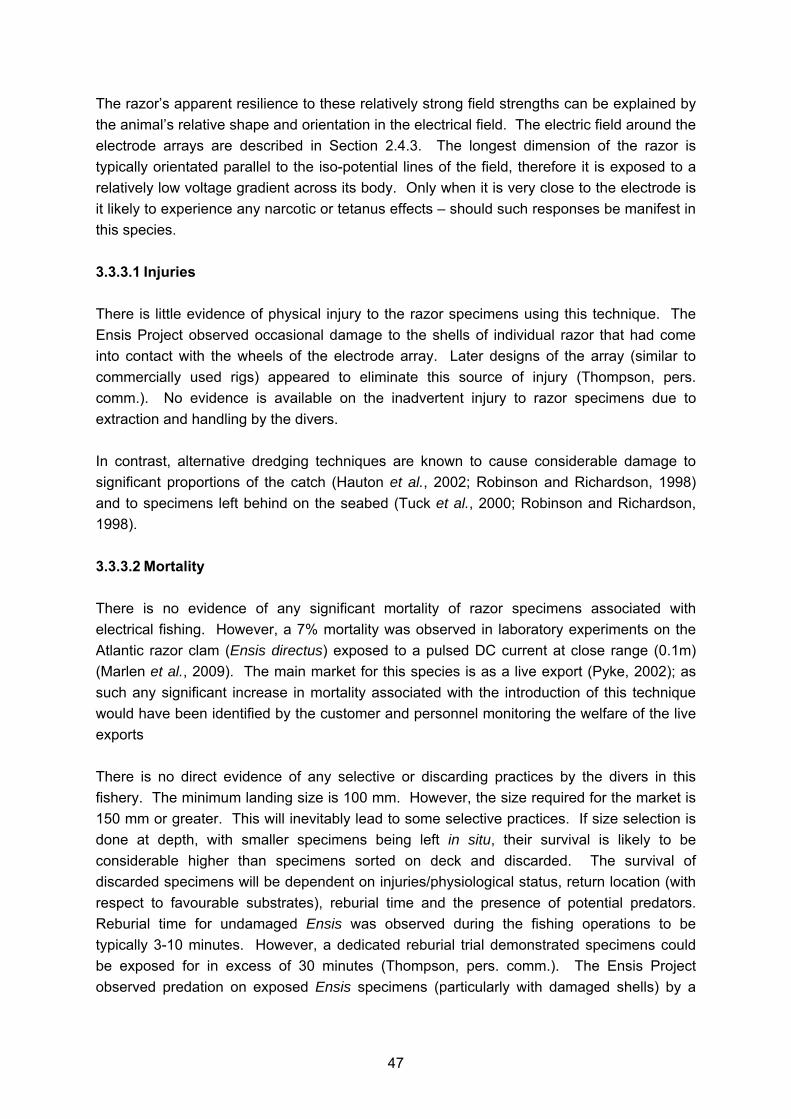
101
* Foot retractor muscle posterior to ligament insertion Solen marginatus Straight sided shell up to about 12cm in length. Yellow in colour with light brown periostracum. Shell sculptured with smooth concentric lines and prominent groove just behind the front margin, Growth stages clear. Key identification features: * Only one tooth in the left valve and no horizontal teeth * Vertical groove on the outside of the shell behind front margin * Anterior adductor scar not as long as ligament Ensis directus Slightly curved shell up to about 15cm in length. Greyish violet in colour with olive green periostracum. Shell sculptured with smooth horizontal and vertical lines with clear growth lines. Key identification features: * Pallial sinus reversed S-shape pointing to posterior adductor scar * Relatively broad shell (length: breadth ratio of 6:1) * Posterior adductor scar very close or joined to pallial sinus * Foot retractor scar opposite ligament insertion Ensis siliqua var. minor Elongate shell up to about 17cm in length. Both dosal and ventral edges of the shell are straight. White or creamy white in colour with red-brown streaks streaks. Periostracum dark green to yellow-green. Shell sculptured with smooth horizontal and vertical lines with clear growth lines. Key identification features: * Dorsal and ventral edges of the shell straight * Distance of anterior scar from shell edge much less that of the ventral scar * Posterior gape compressed * Anterior edge truncated

102
Appendix IV Length Frequency of Ensis arcuatus (Figures 3-9) and Ensis siliqua (Figures 10-11) in various locations from 1989 survey (McKay, 1992).

103

104
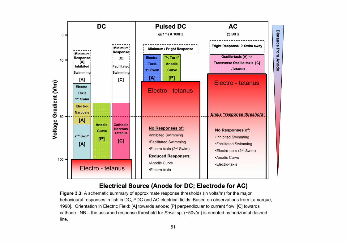
105

106

107

108

109

110

111
Appendix V By catch data from Western Isles Study (Anon, 1998). A list of the larger species caught as by catch is provided in Table 3.1.4. These species are listed in approximate order of abundance, averaged over the whole study. Species Abundance (average number per
tow) Echinocardium cordatum
Heart urchin Very common - 120
Dosinia lupinus Very common - 30
Venus striatula Very common - 20
Lucinoma borealis Northern lucine Common - 5
Gari fervensis Common - 3
Carcinus maenas Shore crab Common - 6
Lutraria lutraria Common otter-shell Less common - 3
Artica islandica Iceland-cyprina (Quahog)
Less common - 2
Mya truncata Blunt gaper Less common - 2
Donax vittatus Banded wedge-shell Less common - 2
Mactra corallins Rayed trough-shell Less common - 2
Liocarcinus depurator Swimming crab Less common - 3
Corystes cassivelaunus
Masked crab Less common - 3
Pagurus bernhardus Hermit crab Less common - 1
Acanthocardia aculeata
Spiny cockle Rare - 1
Venerupis pullastra Pullet carpet-shell Rare - 1
Crangon crangon Brown shrimp Rare - 3
Cancer pagurus Edible crab Rare - 1
Ammodytes lanceolatus
Greater sandeel Rare - 2
Buccinum undatum Whelk Rare - 1
Pleuronectes platessa Plaice Very rare - 1
Aphrodita aculeata Sea mouse Very rare - 1

112
Appendix VI Infaunal Data Infaunal species recorded from each of six experimentally fished tracks (12 -13) from the Western Isles study (Anon, 1998) C- porifera, P- polychaete, R - lower crustacean, S - amphipod, W - mollusc. Numbers recorded at each site throughout study, * - 1-9, ** - 10-99, *** >100. Species 12 13 18 19 22 23 Microciona macrochela
C *
Parapionosyllis minuta
P *
Harmothoe ljungmani
P *
Harmothoe marphysae
P *
Pholoe inornata P * * Eteone flava P * Eteone longa P * * * * * * Mysta picta P * Pseudomystides limbata
P *
Anaitides groenlandica
P *
Anaitides mucosa P * * Anaitides rosea P * Glycera alba P * * * Glycera celtica P * Glycera dayi P * Glycera tesselata P * * Goniadella bobretzkii
P *
Hesionidae sp. P * Kefersteinia cirrata P * * Microphthalmus similis
P * * *
Streptosyllis bidentata
P *
Streptosyllis websteri
P * * ** ** ** ***
Syllides benedicti P * Brania clavata P * Exogone hebes P * * ** ** *** ** Exogone naidina P * ** * Exogone verugera P * * Sphaerosyllis sp. P * * Sphaerosyllis bulbosa
P *
Sphaerosyllis tetralix
P *

113
Lycastis brevicornis P * Nephtys hombergii P * Nephtys longosetosa
P ** ** ** ** ** **
Lumbrineris latreilli P * * * Lumbrineris tetraura
P *
Protodorvillea kefersteini
P * *
Scoloplos armiger P * * * * ** Aricidea minuta P * * *** *** *** *** Aricidea catherinae P * * Poecilochaetus serpens
P * * *
Spionidae sp. P * Aonides oxycephala
P *
Aonides paucibranchiata
P * * **
Malacoceros tetracerus
P * * * * * *
Minuspio cirrifera P * * * Prionospio ehlersi P * Pygospio elegans P * * * Scolelepis bonnieri P * Scolelepis squamata
P *
Scolelepis tridentata
P *
Spio sp. P * Spio armata P * Spio decorata P * Spio filicornis P * * * * * Spio martinensis P * * Spiophanes bombyx
P * * * * * *
Magelona alleni P * * Magelona filiformis P ** * * * ** ** Magelona mirabilis P ** * * Magelona wilsoni P * Chaetozone setosa P ** ** ** ** *** *** Cirratulus cirratus P * Flabelligeridae sp. P * Capitella sp. P * * * * ** *** Mediomastus sp. P * * Notomastus sp. P * * * * * * Baldia johnstoni P * Praxillura longissima
P * *
Euclymene droebachiensis
P * * * *
Praxillella praetermissa
P *
Scalibregma inflatum
P * *

114
Owenia fusiformis P * * Amage auricula P * Terebellides sp. P * Amphitritinae sp. P * Eupolymnia nebulosa
P *
Lanice conchilega P * * * * Phisidia aurea P * Polycirrus medusa P * ** * COPEPODA sp. R * * * * OSTRACODA sp. R * Perioculodes longimanus
S * *
Pontocrates arenarius
S ** ** ** ** ** **
Synchelidium maculatum
S *
Parapleustes bicuspis
S *
Leucothoe spinicarpa
S *
Urothoe elegans S * * * Metaphoxus fultoni S * Tryphosites longipes
S *
Dexamine spinosa S * Dexamine thea S * * Ampelisca diadema S * Ampelisca gibba S * Ampelisca macrocephala
S * *
Bathyporeia guilliamsoniana
S * *
Bathyporeia nana S * * * * * * Bathyporeia pelagica
S ** ** ** * * *
Bathyporeia pilosa S ** ** * ** * Bathyporeia sarsi S * * Megaluropus agilis S ** ** ** ** ** * Cheirocratus assimilis
S *
Microprotopus maculatus
S *
Corophium sp. S * Siphonoecetes kroyeranus
S * * *
Parvipalpus capillaceus
S *
Idotea pelagica S * * * Cumopsis goodsiri S * * * Cumopsis longipes S * * Bodotria arenosa arenosa
S *
Iphinoe trispinosa S * * * * Cumella pygmaea S *

115
Pseudocuma gilsoni
S *
Pseudocuma longicornis
S * ** * * * *
Lamprops fasciata S * Diastylis laevis S * Retusa sp. W * Retusa truncatula W * Nuculoma tenuis W * * Thyasira flexuosa W * Lasaea sp. W * Semierycina nitida W * Mysella bidentata W * Tellimya ferruginosa
W * * * *
Astarte sulcata W * * * * Cerastoderma edule
W *
Spisula solida W * Lutraria lutraria W * Ensis arcuatus W * * * * Angulus tenuis W * * * * * * Fabulina fabula W ** * * Moerella donacina W * Gari tellinella W * * Gari depressa W * Abra alba W * Abra prismatica W * * Circomphalus casina
W *
Dosinia exoleta W * * * Clausinella fasciata W ** * * * ** ** Mysia undata W * * Turtonia minuta W * * * Thracia pubescens W * * Cochlodesma praetenue
W * * *
Amphiura chiajei ZB * Amphiura filiformis ZB * Echinocardium cordatum
ZB * * *
116
Appendix VII Examples for Marine Fish of Reaction Thresholds to Different Electrical Fields Current Minimum Response Threshold Field Strength (V/m) Reference
Minimum / "Fright" Electro- taxis Electro-
narcosisElectro-tetanus
Mullet (Mugil auratus ) (~20cm)AC, 50 Hz (Uniform field) 2.5 - - 13.8 Bary (1956)DC towards cathode (Uniform field) 4.5 - - - Bary (1956)DC towards anode (Uniform field) 8.0 10.5 28.6 - Bary (1956)PDC, 5000μs, 4.0Hz (Uniform field) - 16.0 - - Bary (1956)PDC, 4000μs, 17.0Hz (Uniform field) - - - 40.0 Bary (1956)PDC, 1000μs, 4.5Hz (Uniform field) - 21.5 - - Bary (1956)PDC, 240μs, 4.9Hz (Uniform field) - 39.0 - - Bary (1956)PDC, 120μs, 5.0Hz (Uniform field) - 51.0 - - Bary (1956)PDC, 115μs, 32.0Hz (Uniform field) - - - 110.0 Bary (1956)
Flounder (Platichtys flesus )(~20cm)AC, 50 Hz (Uniform field) ~2.5 - - ~14.0 Bary (1956)DC towards cathode (Uniform field) ~5.0 - - - Bary (1956)DC towards anode (Uniform field) ~7.5 - - - Bary (1956)
Seabass (Dicentrarchus labrax )(~20cm)AC, 50 Hz (Uniform field) - - - ~14.0 Bary (1956)DC towards cathode (Uniform field) - - ~29.0 - Bary (1956)DC towards anode (Uniform field) 8.0 - - - Bary (1956)
Cod (Gadus morhua ) PDC, 20Hz, 5ms 4.0 6.0 - - Daniulyte et al, 1987 (cited by Polet, 2010)PDC, 20-80Hz, 5ms - - - 14-20 Daniulyte et al, 1987 (cited by Polet, 2010)
Herring (Clupea harengus )PDC, 20-40Hz, 2.5-5ms - 10-22 - - Daniulyte et al, 1987 (cited by Polet, 2010)PDC, 80-100Hz - - - 18-22 Daniulyte et al, 1987 (cited by Polet, 2010)
Scaled sardine (Harengula jaguana )PDC, 15-55Hz, 62.5A - 15.0 - - Klima, 1972PDC, 8-28Hz, 86.5A - 30.0 - - Klima, 1972
Spanish sardine (Sardinella aurita )PDC, 35-45Hz, 43.3A - 15.0 - - Klima, 1972PDC, 15Hz, 86.5A - 30.0 - - Klima, 1972
Round herring (Etrumeus sadina )PDC, 25-45Hz, 86.5A - 30.0 - - Klima, 1972
Thread herring (Opisthonema oglinum )PDC, 15Hz, 62.5A - ? - - Klima, 1972
Silver anchovy (Engraulis eurystole)PDC, 35-45Hz, 98.3A - 30.0 - - Klima, 1972
Butterfish (Lepidocybium flavobrunneum )PDC, 35Hz, 41.3A - 15.0 - - Klima, 1972PDC, 45Hz, 86.5A - 30.0 - - Klima, 1972
Chub Mackerel (Scomber japonicus )PDC, 15Hz, 53.8A - 15.0 - - Klima, 1972
Rough Scad (Trachurus lathami )PDC, 15-25Hz, 42.3A - 15.0 - - Klima, 1972
Round Scad (Decapterus punctatus )PDC, 15Hz, 43.3A - 15.0 - - Klima, 1972
Spot (Leiostomus xanthurus )PDC, 15-35Hz, 43.3A - 15.0 - - Klima, 1972
longspine porgy (Stenotomus caprinus )PDC, 25-35Hz, 43.3A - 15.0 - - Klima, 1972

117
Appendix VIII Examples of Observed Mortality in Marine and Anadromous Fish Species Exposed to Different Electrical Fields Species Current Observed Mortality (%) Ref
Short-term (<24hours) Long-term
Cod (Gadus morhua )PDC ? V/m; 0.1m electrode 20% (4/20) 30% (6/20) (14 days) De Haan et al, 2008
Dogfish (Scyliorhinus canicula )PDC ? V/m; 0.1m electrode 0% (0/20)(14 days) 5% (1/20)(9 months) De Haan et al, 2009PDC ? V/m; 0.1m electrode 0% (0/20) 5% (1/20)(9 months) De Haan et al, 2009
Coho Salmon (Oncorhynchus kisutch )PDC 8Hz 40ms Square 0-75% Collins et al, 1954PDC 15Hz 8.3ms 1/2 Sine 2-3% Pugh 1962PDC 15Hz 8.3ms Square 4-9% Pugh 1962PDC 30Hz 8.3ms 1/2 Sine 5-7% Pugh 1962PDC 30Hz 8.3ms Square 6-18% Pugh 1962
Chinook Salmon (Oncorhynchus tshawytscha )AC 60Hz 20ms Sine 0-79% McMillan 1928PDC 2Hz 20ms Square 0-80% McMillan 1928PDC 3-8Hz 20ms Square 0-50% McMillan 1928PDC 10-15Hz 20ms Square 0-75% McMillan 1928PDC 500v, 120Hz 16-25% Maule & Mesa, 1994
Brown trout (Salmo trutta)DC 500V 0-6% Lamarque, 1967DC 400V 0-17% Lamarque, 1967PDC Exponential 0-86% Lamarque, 1967PDC 1/2 Sine 90Hz -11ms 27-89% Lamarque, 1967PDC Square 5Hz 66ms 0-50% Lamarque, 1967PDC 60Hz 8ms 1/2 Sine 0-5% Nehring 1991AC 20.00% Pratt 1955DC 4% Pratt 1955PDC 60Hz 7ms 1/4 Sine 4-35% Meyer & Millar, 1990
© Crown Copyright 2011 Marine Scotland – Science Marine Laboratory 375 Victoria Road Aberdeen AB11 9DB Copies of this report are available from the Marine Scotland website at: www.scotland.gov.uk/marinescotland