a review of free, forced and mixed convection in a saturated porous annulus
TRANSCRIPT

Sfuthan& Voi. 15, Part 1, June 1990, pp. 1-41. © Printed in India.
A review of free, forced and mixed convection in a saturated porous annulus
K MURALIDHAR
Department of Mechanical Engineering, Indian Institute of Technology, Kanpur 208 016, India
MS received 2 April 1990
Abstract. A computational study of heat transfer in a liquid-saturated porous annulus with a heated inner wall and a cold outer wall is reported here. Results are presented for heat transfer rates from the inner cylinder for a wide range of parameters which characterize free, forced and mixed convective regimes of flow. Both horizontal and vertical annulii are included in the study. Heat transfer results have also been obtained from a non-Darcy model for flow and these are compared to the Darcy solutions. Non-Darcy effects are taken to arise from inertial and viscous effects in the fluid phase and the variation of porosity near the solid wall. The approach of heat transfer results of an annulus with a large radius ratio towards those of an isolated circular cylinder is discussed. Limited data on transient convection is also presented in this work.
Keywords. Free, forced and mixed convection; heat transfer; Darcy and non-Darcy models; saturated porous annulus; numerical solution.
1. Introduction
The present study has been carried out to analyse flow and heat transfer in the vicinity of buried nuclear waste canisters. It has been proposed that cylindrical containers filled with partially radioactive wastes be disposed under the surface of earth so as to isolate them from the human population. In assessing the safety of this practice, it is important to know the maximum surface temperature reached on the surface of the container under a variety of flow conditions. In the absence of a pressure gradient, the mean groundwater motion is zero. The temperature distribution on the cylinder surface is ~ "n determined by conduction at low heat flux levels and by buoyancy- driven r'~lavection at larger heat fluxes. In the presence of a mean flow past the cylinde,, t~e surface temperature is determined by forced convection. It can be further augmented by buoyancy-driven motion of the fluid at large heat flux levels. Hence
A list of symbols used is given at the end of the paper

2 K Muralidhar
it is important to study heat transfer around a cylinder buried under earth in all three possible regimes, namely free, forced and mixed convection.
The problem addressed here is heat transfer in an annulus filled with a fluid- saturated porous material. The inner cylinder models the nuclear-waste canister which is at a temperature higher than the ambient value, the heating arising from the remnant decay of the waste material. The outer cylinder represents a low permeability host rock or formation and the porous material is the backfill surrounding the canister. In the application addressed here, the fluid which saturates the porous material is water. Though the permeability of the backfill is initially small, it is expected to crack with the passage of time and hence permit both groundwater and free-convective flow past the inner cylinder. As the radius ratio R = R2/R1 increases, the annulus geometry models a single isolated cylinder in a porous medium. The present work includes both vertical and horizontal configurations of the annulus. This is relevant when buoyancy forces become an important factor in determining the flow regime as free, forced or mixed.
Results have been presented here for the following range of parameters.
Free'convection Ra <~ 104, 1.1 ~< R ~< 3. Forced convection All Pc, 1.1 ~< R ~< 3. Mixed convection Pe ~< 10, Ra ~< 500, 1.1 ~< R ~< 3.
The heat transfer rates have been computed using the Darcy model for flow. These have been compared to results obtained from a non-Darcy model. The latter includes inertial and viscous forces in the fluid phase and the variation of porosity of the medium near a solid boundary. Lastly, the duration of transients is briefly discussed.
Many of the results presented in this review have been reported earlier (Muralidhar & Guceri 1986; Muralidhar et ai 1986; Muralidhar & Kulacki 1988; Muralidhar 1989; and also see additional references therein the area of free convection in a porous annulus). Recent work on convection in a porous medium in cylindrical geometries include the following, Kimura (1989) on transient free and'forced convection around a vertical cylinder, Kumari & Nath (1989) on non-Darcy mixed convection boundary- layer flow past a vertical cylinder, and Nakayama et al (1989) on non-Darcy free convection from a curved surface. Non-Darcy effects referred to in the papers above deal only with inertial forces in the fluid phase.
This paper is organized in the following manner: mathematical formulation of Darcy and non-Darcy problems (92), numerical solution (93), comparison of numerical solution with published data (§4), results and discussion (9 5), and conclusions (96).
2. Mathematical formulation
Steady flow in a low-permeability porous medium is governed by Darcy's law (Bear 1972),
u = - ( K / ~ ) ( V # - p g ) . ( 1 )
Equation (1) includes fluid motion arising from a regional pressure gradient as well as local flow arising from a density distribution. It is assumed here that density variation occurs due to a temperature distribution through the relation,
p=po[1-fl(T- To)],

C o n v e c t i o n in a s a t u r a t e d p o r o u s a n n u l u s 3
where subscript 0 refers to cold (or free stream) conditions. Hence the heated canister generates both a temperature and a density field around it. It is also assumed that the effect of temperature variation on other flow properties /~, v and ct and the (geological) formation properties e and K is negligible or can be represented by an average value valid for the temperature range of interest. K, the permeability of the porous medium is a measure of the ease with which flow can occur for a given pressure drop or a density increment. Defining p =/~ + P o O Z , (1) can now be written as,
u = - ( K / I ~ ) [ V p + Pof l ( T - To)g ]. (la)
The temperature field is obtained by solving the energy equation,
u.VT = aV 2 T. (2)
The composite form of ct arises from the consideration that the solid phase of the porous medium is stationary and convection refers to the fluid phase alone. However, both the solid and the fluid contribute to diffusion and k,~ is an equivalent thermal conductivity of the medium. For a system consisting of a solid and a fluid of comparable conductivities, km is given as,
km=/3kfluid -1- (1 - - •)ksoli d .
Here e is the porosity of the medium defined as the ratio of volume of the pore (fluid) space to the total volume.
u and Treferred to above in (la) and (2) must be interpreted as space averaged velocity and temperature over representative elementary volumes (REV) of the porous medium. The size of the REV is assumed to be large enough so that local variations in u and T due to the complex geometry of the pore space are averaged, but small enough for derivatives in the governing equation to have a meaning. The interstitial fluid velocity in the pores is related to that averaged over the REV as u/e. For regions where e--, 0, lul will approach zero as e n where n > 1.
Equations (la) and (2) are solved subject to the constraint of incompressibility,
V- u = 0, (3)
which is assumed to hold despite the dependence of fluid density on temperature. This is called the Boussinesq hypothesis and it has been tested quite extensively in free convection problems. It is taken to be valid as long as the temperature difference does not become large.
Expanded forms of (la), (2) and (3) are given below for some simple geometries.
2.1 V e r t i c a l a n n u l u s
For a vertical annulus with wall boundary conditions independent of 0, the angular coordinate, both flow and heat transfer in free, forced and mixed convection are two-dimensional in the r - z directions. The directions of z and Z now match and g = - g k (see figure lb). The governing equations are:
V.u = ur + (u/r) + w: = O,
u = - (K/ l~)p , ,
w = - (K / l~ ) [pz - P o g f l ( T - To)],
(wL+uT,)--~[T,,+(1/r) T,+ T~:] =0. (4)

4 K Muralidhar
(o) (b) (c) Figure 1. Flow domain and coordinate system. (a) Horizontal annulus, (b) vertical annulus, (c) horizontal annulus with parallel flow.
2.2 Horizontal annulus
For uniform boundary conditions along the cylinder walls, free convection in a horizontal annulus is two-dimensional in the r-O directions. This is shown in figure la. Forced convection in a horizontal annulus is two-dimensional in the r - z directions. This case is identical to its counterpart in the vertical configuration. However, the mixed convection problem (figure lc) which has a mean flow in the z-direction is three-dimensional and is governed by the following equations:
V . u = u, + (u/r) + (1/r)v0 + w= = o,
u = - (KIlO[P, + Pogfl( T - To)cos 0],
v = - (K/lO[(1/r)po - Pogfl( T - To) sin 0],
w = - ( r / ~ ) p ~ ,
[wT~ + uT, + (v/r) To] - ~t[ 7",, + (l/r) T, + (1/r 2) Too + T~=] = O. (5)
Here, g is written as g (cos 0, - sin 0) in the r and 0 directions. As shown in figure la, 0 is the angle measured with respect to the gravity vector. For a free convection problem, we set w and T== = 0 in (5). For a forced convection problem, u = v = To = O.
2.3 N on-dimensionalization
For a free convection problem, we use a velocity scale a/AR, a pressure scale ct#/K, a length scale AR and a scale AT for the temperature difference ( T - To). For the walls of the annulus maintained at Tn and To, AT = T u - To. For a prescribed heat flux q on the inner wall and a cold outer wall, AT = qAR/k=. In either case we identify the reference condition To and Po as Tc and Pc, respectively. Equation (4) can now

Convection in a saturated porous annulus 5
be written in a compact form as,
V.u=0, 1 u = - Vp + Ra Tk, (vertical annulus),
u . V T - V 2 T = 0,
V .u=0 , }
u = - Vp - Ra T(cos 0, - sin 0), (horizontal annulus).
u . V T - V2 T = 0,
u, p and T now refer to dimensionless variables. For the vertical annulus, u = (u, w) and V = (a/dr, d/t~z). For the horizontal annulus, u = (u, v) and V = [tg/dr,(1/r)(d/c~O)]. The dimensionless equations given above contain one dimensionless parameter Ra = gflAT KAR/v~t, called the Rayleigh number. It is interpreted as the ratio of work done by buoyancy forces to the energy lost as viscous dissipation. Clearly, large values of Ra generate strong buoyant flows in the annulus.
In homogeneous fluid problems Ra is defined by replacing KAR with AR 3. For this reason, Ra used in this work is sometimes called the modified Rayleigh number.
In mixed and forced convection problems, the velocity scale is chosen as if, the prescribed velocity at the inflow plane of the annulus. The pressure scale is Poff2- The following equations can now be derived:
V'u =0, 1 u = - Vp + (Ra/Pe) Tk, (vertical annulus),
u - V T - (1/Pe)V 2 T = 0,
V.u=O, } u = - Vp - (Ra/Pe) T(cos O, - sin O, 0), (horizontal annulus).
u-VT - (I/Pc) V 2 T = O,
In these equations, Ra is the Rayleigh number defined earlier and Pe is the Peclet number, ¢vAR/ct. Pe is interpreted as the ratio of convective heat transfer from a surface to the conductive heat transfer in the absence of flow. Clearly, as Pe increases the total heat transfer from a surface increases.
2.4 Stream function formulation
For free convection problems, the flow is two-dimensional and a stream function @ can be expected to exist. A calculation in terms of @ guarantees that the incompressibility constraint is identically satisfied. For a vertical annulus, we define ~k through the velocity components as, u = -(1/r)@~ and w =(1/r)~kr. The component equations which are based on Darcy's law can be combined to eliminate pressure as a variable. This yields,
w, - u~ = Ra T,, and in terms of ~k,
~b,, - (1/r)~b, + ~b~ = Ra T,.
This equation along with the energy equation provides a complete description of the flow and temperature field. For the problems studied in this paper, the ~ - T equations

6 K Muralidhar
are summarized below.
Vertical annulus:
u = - ( l / r ) ~ , w = ( 1 / r ) ¢ , ,
~b,, - ( 1 / r ) ~ , + ~b~ = R a T , ,
(uT, + wT,) - [ :r,, + (1/0 T, + T,z] = 0,
I (free convection), (6a)
~b,, - (1/r)~,, + ~b=.= (Ra/Pe) T,, ~ (mixed convection). (6b) (uT, + wTz) - (1/Pc)[ T~, + (l/r) T, + T~] = 0, )
Horizontal annulus:
u = - ( 1 / r ) ~ , v = ~ , , ]
~b,, + (l/r)~, + (1/r2)~boo = Ra [sin 0 T, + (cos O/r) To], / (free convection).
[uT~ + (v/r) To] - [ 7",, + (l/r) 7", + (1/r 2) T0~ ] = 0, (7)
Mixed convection in a horizontal porous annulus is inherently three-dimensional and a stream function does not necessarily exist. One may intuitively view flow in this geometry as consisting of a mean velocity superimposed by a buoyancy-driven motion which imparts swirl to it. Using a series of assumptions it is possible to describe the secondary buoyant flow in terms of a stream function. This approach is developed below.
It is first assumed that the derivatives in the mean flow (i.e., z) direction are small so that Tz~ can be dropped in (5). This permits a marching procedure for T along the length of the annulus, for a known initial profile for temperature of the incoming flow. The assumption that Tz~ is much smaller than other diffusion related derivatives requires that Pe not be small, i.e., Pe > 1. The second assumption is with regard to pressure. The pressure field is taken to be of the form,
p(r, O, z) = if(r, O) + ~(z). (8)
This is justified whenever the mean flow does not undergo a reversal and the secondary flow is driven by a pressure field i(r,O). Since w = - p ~ , from (5), the above decomposition gives,
w = - (d~/dz)(z). (8a)
Equation (8a) can be solved by using the constraint of mass conservation,
Solving for the pressure gradient, one obtains - (dp /dz )= 1 everywhere and hence w(r, O,z)= 1 in the annulus. The incompressibility constraint in (5) reduces to its equivalent two-dimensional form,
u, + (u/r) + (1/r)v0 = 0,
thus permitting the use of a stream function. Eliminating if(r, 0) from the u and v components of (5), one obtains,

Convection in a saturated porous annulus 7
~b,, + (1/r)~b, + (1/r2)~boo
= (Ra/Pe) [(l/r) cos 0 T 6 + T, sin 0], (mixed convection), (9)
(dT/dz) = (1/ae)[ T,, + (I/r) T¢ + (l/r z) Too ]
- JuT, + (v/r) To],
The above procedure is called parabolization of a set of partial differential equations which are in general elliptic. It reduces a full three-dimensional problem to a sequence of two-dimensional problems that are generated by marching in the flow direction. The reduced problem is easier to solve using numerical methods.
2.5 Boundary conditions
The if- T equations given above must be solved subject to the following boundary conditions. The coordinate system used is shown in figures la-c.
Free convection:
r= R I , R 2, ~ = 0 ,
z=O, AR, ¢ = 0 ,
r = R l, T = I or T r = - l ,
r=R2 , T=0 ,
z =O, AR, T z=O.
r= R t , R 2, ~b=O,
0 = 0,,r, ¢ = 0 ,
r = R I, T = I or T , = - I ,
r = R 2, T=0 ,
O=O,n, To=O.
Mixed convection:
(vertical annulus), (10a)
(hodzontal annulus). OOb)
r=Rl~b=0 , T = I or T , = - 1 , ]
r= R2~k 0-5(R 2 - R2), T=O. ~ ~ (vertical annulus), (10c)
r= R1,R 2, ~b=0,
O=O,n, ~ = 0 ,
r = R 1, T = I or T , = - I , (horizontal annulus). (10d)
r = R 2, T=0 ,
0=0,~r To=O ,
z=0 , T=0 .
In (10a), AR is the aspect ratio, (= height/gap width) of the annulus. Results are

8 K Muralidhar
presented in this work mostly for AR = 10. The top and bottom planes at z = 0 and AR are treated as insulating and the outer wall at r = R 2 is a cold wall. The inner cylinder (r = R 1) is heated and sustains the buoyant motion. The thermal boundary condition on this surface could be the prescribed heat flux q or a prescribed temperature T u. Through the appropriate temperature scale AT, these reduce to T, = - 1 and T = 1 respectively. Similar remarks are valid for (10b)-(10d). For a horizontal annulus, 0 = 0 and 0 = n represent symmetry planes. Since ~b in (10d) refers to the secondary flow it is zero on the bounding planes of the annulus. It is assumed in (10d) that the outer wall temperature is identical to that of the incoming fluid at z = 0. The forced convection problem is recovered from the mixed convection problem by setting Ra = 0 in the governing equations.
Equations (6), (7) and (9) have been solved in this study subject to the boundary conditions, (10), for a wide range of parameters Ra, Pe and R2/R I. Results are presented in terms of the local Nusselt number, Nut, evaluated on the inner wall. For a surface with a prescribed wall temperature, the normalized Nusselt number can be shown to be,
Nut = - ~ = R1 R I nR-/l, on the inner wall, and
Nu, = ( t 3 T I r - &-r] = Rz) /R21n~-~, on the outer wall.
These definitions give Nu = 1 when Ra = 0, the conduction limit and an increasing rate of heat transfer for increasing values of Ra and Pe. For a constant flux surface on the inner wall, we have
Nu I = 1/T(r = R1).
This definition gives low wall temperatures for large Nu~, indicating the presence of a good heat removal mechanism in the annulus. The average Nusselt number is
Nu = (1/AR) Nu t dz or Nu = (l/n) Nuld0.
For a constant flux inner wall and an isothermal (cold) outer wall, the average Nusselt number at the diffusion limit (Pe = Ra = 0) as a function of the radius is summarized in table 1.
In the nuclear waste application referred to earlier in this paper, the magnitude of the dimensional quantities is as follows:
u = 1-100 m/year,
Table !. Diffusion Nusselt numbers in an annulus with constant heat flux on the inner wall.
R2/R 1 NU
1"1 1"049 2'0 1 '4426 3'0 1 "8204

Convection in a saturated porous annulus 9
q = 100W/m 2,
R1 ,-- 0-5 m and AR-,- lm.
The properties of water at an average temperature of 50°C are used here to determine Ra and Pe. [ p = 9 8 8 k g / m 3, /~= 5.4 x 10⁻⁴kg/ms, v= 5.5 x 10-Tm2/s, k = 0.6432 W/mk, fl = 46 x 10- S/K, Cp = 4179-7 J/kg K, a (water) = 15.6 x 10- s m2/s.]
being the porosity of the medium, the effective properties k,. and ~t are, km ~ ek and ct ~ ect (water), assuming that the solid phase is non-conducting. We then get the following estimates:
0.2/e < Pe < 20/e and Ra ~ 1014.K/e 2,
where K is the permeability. In the early stages after waste disposal, K is small (-,, 10-2°m 2) and e is of the order of 0-01. With the passage of time, the medium around the waste canister cracks and K can increase by several orders of magnitude. e is not expected to increase beyond 0-1 (see Chapman & Mckinley 1987). These estimates of Pe and Ra show that all the three heat transfer regimes, namely free, forced and mixed convection must be considered in analysis.
2.6 Non-Darcy formulation
The Darcy equations, [see §2, (1)] can b_e derived from the Navier-Stokes equations by dropping the inertial terms and averaging the flow in a space formed by an assembly of spheres. Hence the permeability K of a porous medium is inversely proportional to the drag acting on densely packed particles. When the inter-particle spacing increases, a part of the pressure drop goes towards overcoming viscous friction in the fluid phase and another towards accelerating the fluid particles from one velocity profile to another. The criterion for neglecting these higher order effects in an isothermal flow is Re = luld/v < 1. In flows which are modified by heat transfer, this criterion is not adequate. It is of importance to see whether these effects can alter the inner wall Nusselt number in the nuclear waste application.
The modified Darcy equations including viscous friction in the fluid phase and acceleration (inertial) effects is given in coordinate-free form as,
e(#/K)u - (/~/e)V 2 u + (9Fe 2 tulu)/K ½ = - Vp + Pogfl( T - To)k. (11)
The term ~V2u refers to viscous effects in the fluid phase and is called the Brinkman correction to Darcy's law. Since it is an empirical correction,/~ need not coincide with the dynamic viscosity of the fluid. Viscous effects are found to be small in this work and the distinction between/~ and ~ is ignored here. The second correction to Darcy's law arises from the term (pFe 2 lulu)/K*. This is called the Forschheimer term and it accounts for inertial forces in the fluid phase. It is written in general as blulu, where b is a proportionality constant. Since the Forschheimer term represents form drag, the pressure drop due to inertial effects is taken to be proportional to the square of the velocity. The appearance of the product lulu makes (11) nonlinear. The signs of the viscous and inertial terms are chosen so as to imitate the Navier-Stokes equations at the limit K--* o0 (the homogeneous fluid problem).
The specific form of the inertial correction term is applicable to a porous bed of spheres. This is a reasonable approximation of a homogeneous and isotropic porous medium. Then, F, the empirical factor in the Forschheimer term is given as,
F = 1.75/(150~e,~).

10 K Muralidhar
Experiments show that F lies between 0-014 and 1 (Beavers & Sparrow 1969). [See Vafai & Tien (1981) and Vafai 0984) for a further discussion on non-Darcy effects.] A complete numerical solution of (l l) for non-Darcy convection in a rectangular cavity is presented by Lauriat & Prasad (1989).
The factor e in (11) arises from the fact that inertial and viscous forces appear in the fluid phase and hence must be calculated with reference to the interstitial fluid velocity (and not the volume averaged velocity). The temperature field in (11) is determined from the energy equation,
eu .VT = ~V 2 T. (12)
Equations (1 l) and (12) are non-dimensionalized using the scales defined for the Darcy problem with the exception that the velocity scale is o~/eAR for the free convection problem. This results in the following system of equations
u - (Da/e)V2u + (F/Pr)Da½u[ul = - Vp + Ra Tk [ (free convection). (13) u.VT= V2 T, !
For the mixed convection problem, Ra is replaced by Ra/Pe and V 2 T by (l/Pe) V 2 T. For the waste disposal problem studied here, Da is small since K is small and AR is of order unity (in metres).
In (13), the viscous correction is of the order of Da while the inertial correction is of the order of Da ½. Based on the magnitudes of K and AR given earlier, one estimates Da as, 10-1° > Da > l0 -2°. Hence viscous friction can be ignored in the bulk of the porous medium except near the boundaries. The viscous terms are of order unity in the vicinity of the wall over a distance Da½/e. The analysis of this region is presented separately later in this paper.
The inertial terms are of order Da ½ and are not necessarily small. These are retained in the non-Darcy analysis of flow and heat transfer. It is noted here that (13) shows an explicit dependence on the Prandtl number Pr through the inertial terms, though this dependence is absent in the Darcy equations (6), (7) and (9). Hence in the presence of inertial forces, the Nusselt number Nu is given as,
Nu = Nu(Ra, Pr, R2/R 1, AR, Pe).
It is seen in the present study that wall heat transfer is strongly affected by the variation of porosity near a solid boundary. The experimental work of Benenati & Brosilow (1962) shows that the porosity near the wall is larger than the mean porosity and is accompanied by rapid fluctuations. It is assumed here that these fluctuations are within the representative elementary volume used in the formulation of the governing equations and that only the envelope of the pointwise distribution is important. This envelope is assumed to be of the form,
e/~ = I + Dexp [ - ~(r - R1)/dp], (14)
D and ? are affected by the curvature of the bounding wall and the particle diameter dp. However, only parametric studies with respect to these quantities are presented. Assuming that the porous medium is a bed of spherical particles, the local permeability is related to the local porosity by the Cozeny-Karman equation (Bear 1972),
g ~--- ( E 3 d 2 ) / [ - 1 8 0 ( | - - E)2~].
The effect of increase in e (and hence K) near the wall permits additional flow in this region and hence a raise in heat transfer over and above the Darcy value. This

Convection in a saturated porous annulus 11
increase in velocity is called 'channelling'. Besides inertial and viscous effects, the variation of porosity near the wall leading to channelling of flow is treated in this study as the third source of deviation of real flows from Darcian behaviour.
The governing equations for Darcian free convection in a horizontal porous annulus including the dependence of e and K on the radial coordinate are the following:
e(r)u = (- K(r)/Ig)[Vp - Pogfl( T - To)k ],
e(r)o.VT = V 2 T. (15)
The dimensionless form of governing equations for non-Darcy flow in terms of the stream function ~b and temperature T for free convection in a horizontal saturated porous annulus is given below. As discussed earlier, viscous effects in the fluid phase, being of the order of the Darcy number, have been dropped altogether. Inertial terms and the dependence of t and K on r have been retained. The mean porosity ~ and the mean permeability/~ (based on g) have been used as the porosity and permeability scales, respectively. The ¢ - T equations are:
a ~,a~k t~ 1 d~ . To), ~r(rl ~r )+ ~-O(r I~'~-) = r R a ( s m 0 cosO T,+- S - /
e(uT,+ v T o ) - ( T,+! T,+-~ Too)=O, (16)
where
and I* = (t/K) + (Fe 2 lul/Pr).(Da/K) ½,
lul = (u 2 + v2)L
Similar equations can be written for other configurations of the annulus and flow regimes.
3. Numerical solution
The stream function and temperature equations, (6a), (6b), (7), (9) and (16), and associated boundary conditions (10) have been solved using two different numerical methods. The first method is based on a control-volume type of finite differencing while the second uses a Taylor's series approach. The control volume formulation can treat variable node spacing near the solid walls without any particular difficulty. In the second method, the grid is generated using an independent set of coordinates whose mapping in the physical domain, i.e. the annulus, consists of non-uniformly spaced nodal points. Both methods produce comparable results for mean values of heat transfer, though the second method produces a better local solution for Nu~. Details of comparison of these methods can be found elsewhere (Muralidhar & Guceri 1986). In view of the overall superiority of the second method, it is described in greater detail below.
The governing equations are first recast in terms of (r/, 0) as independent variables rather than (r, 0). Here, r/= rl (r) and is determined from the equation,
+ = Q(r ) ,
and the boundary conditions tt(R1)= R1 and rI(R2)=R z. Q(r) is a grid control

12 K Muralidhar
Table 2. Maximum and minimum values of nodal spacing as a function of parameters A and C
R2/R 1 A C Aq (Ar)mi. (Ar)m,x
10 0.025 0"0215 0"0264 1"1 20 0"2 0'025 0'0176 0"0305
10 0'025 0'0197 0'0286 2"0 20 0"2 0"025 0"0167 0"0329
10 0"025 0'0198 0"0288 3'0 20 0'2 0"025 0"0166 0"0330
function defined in terms of parameters A and C as
2 Q(r) = - ~, A sign ( t / - rh)exp(- CI~/- ~hl),
i=1
where i = 1 is the inner wall and i = 2 is the outer wall. For positive values of A and C, a uniform distribution of nodes along the t/ axis will produce a non-uniform distribution of nodes along the r coordinate. It is easier to solve for r(r/) rather than r/(r) since the nodes are equidistant on the r/-axis. The unknown function r(r/) is obtained from the inverse of the equation given above, i.e.,
r~+Qr~=O, r (R1)=R 1, r (Re )=R 2,
and ~--(1/r,i) 2. Despite the nonlinearity of this equation, a Taylor's series-based finite difference method is convenient to use and converges fast. Typical values of maximum and minimum values of Ar as a function of A and C are given in table 2.
Since ~/is the new independent coordinate, the r-derivatives in the ~b- T equations are transformed as T, = T~/, etc. The Laplacian
V 2 T = T.. + (l/r) T. + (1/r 2) Too becomes,
V z T = ~ T,~ + [Q + (l/r)] T, + (1/r z) Too
and the convective term
u.VT becomes
(u/r.) T. + (v/r) To.
in transformed coordinates r/(r), the term
(1/r)(rl~'~.). + [(1/r2)I*~bo]o
appearing in (16) can be shown to be.
~(I* ~b~), + [-Q + (l/r)] I*~k~ + [(1/r2)I~'~o]o.
To preserve first-order accuracy in finite differencing, i.e., an error of order (At-) 2, the metric coefficient r~ must be known to an accuracy of better than second order. This condition is accomplished by solving for r(r/) on a grid with at least twice as many points as used in the flow calculation.

Convection in a saturated porous annulus 13
~ E Figure 2. Discretization in cylindrical coordinate system.
Finite differencing of the diffusion terms is straightforward; for example,
T , , ~ ( T,,j+ ~ + T~,j_ t - 2T~j)/(A~/) 2,
where i is an index in the 0 direction and j an index in the ~/direction. The convective term is differenced using an upwind scheme applied to the conservative form
u 'VT = V . ( u T ) = l ~-(urT) + ! ~ ( v T ) . r~r c~l
The upwind formulas are given below for the grid shown in figure 2.
a ~-~ (ur T) = [ (ur T)e - (ur T)w]/Ar I
where (Ur)e = 0"5((ru)p + (rU)E) and (ur)w = 0"5((ru)e + (ru)w).
Te= Te,ifue>O; Te= Tn, i f u ,< 0 ; Tw= Tw, ifuw>0; and
Tw= Tp, ifuw < 0.
-~-o(VT) = [(vT). - (vT)~]/AO
where v. = 0"5(v N + re) and v s = 0.5(v s + re). Further, T. = Tp, if v. > O; T. = TN, if v. < 0; Ts = Ts, if v~ > 0 and T~ = Tp, if v s < 0. These formulae are formally of the first order, though they are known to behave as second-order numerical schemes. Similar differencing rules apply in the r-z coordinate system as well.
The approximate forms of the derivatives are assembled to yield a system of equations each one of which has the form,
AEc~E + Awc~w + ANdPN + AsC~s + AedPe + Se = O. (17)
Here, subscripts E, W, N, S and P stand for the nodes (i,j + 1), (i,j - 1), (i + l , j ) , ( i - 1,j) and (i,j) respectively and ~b stands for g, or T. Se is the source term in the governing equation evaluated at point P. The solution of the coupled system of algebraic equations for ~ and T has been obtained by Gauss-Seidel iteration. Iterations are continued till the convergence between successive flow fields is within 0.01%. No under or over-relaxation parameter has been found necessary for the convergence of the iterations.
Dirichlet boundary conditions such as prescribed temperature or stream function replace the substitution formula, (17), at the boundary nodes. Neumann boundary

14 K Muralidhar
conditions can be easily built into this formula. For example, if To = 0 at 0 = 0, the discretized version of this boundary condition, namely 7"1. ~ = T2, ~ reduces (17) to,
AEdPE + Awc~w + AN(aN + (As + Ae)c~p + Sp = O,
when evaluated on the 0 = A0 line. Calculations for a horizontal annulus have been carried out on a 41 x 41 grid.
Calculations for a vertical annulus have been carried out on a 81 x 41 grid, with a larger number of points in the z-direction. In both configurations, the grid is non-uniform in the r-direction. The grid requirement becomes increasingly relaxed at low Rayleigh numbers and radius ratios. A measure of adequacy of a grid is the excess energy balance computed as a percentage of the energy input at the inner wall. The grid concentration parameters A and C have been chosen so as to maintain an upper limit of 5~o on this quantity. This value is reached in high Rayleigh number and high Peclet number flows in annulii with large radius ratios. In other problems it is quite small, being of the order of 1~.
In mixed convection flow in a horizontal annulus, an iteration scheme is generated for every discrete step taken in the flow direction. Here, the governing equation for temperature is written as
T z = (1/Pc)l- T,r + (l/r) T, + (1/r 2) Too] - (uT, + (v/r) To).
The equation is discretized in the flow direction using an implicit marching scheme,
( T ~+ ' - T~)/Az=(1/Pe)[ T, ,+ (1/r) T, + (1/r 2) Too] "+ ~ - [ u T , + ( v / r ) T0] "+1, (18a)
where the superscript n refers to the present z location at which u and T are known and n + 1, the next location at which they are to be determined. The spatial derivatives are approximated as described earlier for a free convection problem. Equation (18a) is solved simultaneously with the flow equation,
[~b,, + (1/r)~b, + (1/r2)d/oo] "+1 = (Ra/Pe)[T, sinO + (l/r) TocosO] "+ 1. (18b)
Equations (18a) and (18b) are also cast in the form of(17) and solved by Gauss-Seidel iteration. Over the distance 0 < z < 10, typical step sizes used are Az = 0-001 for 0 < z < 1, Az = 0.01 for ~b < z < 2 and Az = 0"02 for other values of z.
In the numerical procedures referred to above, the rate of convergence depends strongly on the initial guess of ~, and T. In the present work, the solution obtained at a given Ra and Pe is used as the initial guess for larger values of these parameters. In the absence Of any information, the conduction solution or the forced flow solution, both of which are analytically given, is used. Convergence is also seen to be accelerated by using first a coarse grid (say, 41 x 21) and using it as the initial guess for a refined grid (say, 81 x 41) calculation.
4. Testing of computer programs
The computer codes developed to implement the numerical procedure described above, have been tested against several published results and analytical solutions. For free convection in a saturated horizontal porous annulus with a constant temperature inner wall and a cold outer wall, results obtained here are compared to those of Caltagirone (1976) in table 3.

Convection in a saturated porous annulus
Table3. Comparison of results of present study with those of Caltagirone (1976). R2/R 1 = 2.
N u t
Ra Nu Min Max ~k.,a~
Reference l0 1.0172 0.759 1.266 1.177 Present work 10 1.025 0-759 1.27 1.17 Reference 200 2.625 0.062 5.23 15.86 Present work 200 2.74 0-173 5.25 16.4
15
Despite differences in the numerical methods used and the reduced number of points used here, the agreement is good. For free convection in a vertical porous annulus with a constant temperature inner wall and a cold outer wall, Prasad & Kulacki (1984) give a correlation for the mean Nusselt number
Nu = 0-47 Ra °'51 A R - ° a 9 ( R 2 / R I ) °'3s, 1 <<. (R2 / R1 ) < 5,
which is accurate to within 10% of their computed results in general, and within 5% in the intermediate range of Rayleigh numbers, 500 < Ra < 5000. The comparison between this correlation and the computer code developed for this work is given in table 4. The agreement is seen to be quite good.
For forced flow in a porous annulus, the temperature field follows the equations,
T. = ( l /Pe)[ T , + (l/r) T~], (19)
r = R1, Tr.= - I; r = R 2' T =O; z = 0 , T = 0 .
These can be solved analytically using the separation of variables method (Ozisik 1980) to yield
T(r, z) = R 1 In (RE/r) + ~ c, R (An, r) exp [ -- 22 (z/Pe)], (19a) n = l
where R = Jo().,r) Yo().,R2) -- Jo(AnR2) Yo(2nr),
c , = [ - ~ R R 2 r R l l n ( R 2 / r ' R ( ) . . , r ' d r l / [ f a i 2 r R 2 ( 2 n , r ) d r l ,
and 2n is the nth root of the equation,
J'o(2nR1 ) Yo(). ,R2) - Jo(2,R2) Y~(2nR1) = 0.
Table 4. Comparison of results of present study with those of Prasad & Kulacki (1984); AR = 10.
R2/R l = 2 R2/R l = 3
Ra Nu(This work) Nu(Reference) Nu(This work) Nu(Reference)
100 2.165 2'072 2"625 2"417 1000 6.75 6.70 7-70 7.82 5000 14.105 15.24 16.69 17.77
10000 18"57 21"7 22'63 25.31

16 K Muralidhar
F i g u r e 3. Ra=0.
0.8
0.4
-~-=2
anolytical
• numericol
I I 0 0.5 1.0 1.5
z/Pe Comparison of analytical and numerical solutions for inner wall temperature.
Jo and Yo are the zeroth order Bessel functions of the first and second kind. A comparison of the analytical solution of (19) and the numerical result is shown in figure 3. Again the agreement is satisfactory.
5. Results and discussion
5.1 General remarks
Most results presented in this work employ the constant heat flux inner wall boundary condition. A few results for a constant temperature inner wall are presented for comparison. With the flux condition prescribed, the wall temperature is obtained as a part of the solution. The Nusselt number Nu is inversely proportional to the wall temperature Tw. Hence, an increase in Nu indicates a lowering in Tw and points towards the existence of a better heat transfer mechanism. With the wall temperature prescribed, at r = R1, the Nusselt number becomes directly proportional to the wall heat flux. In the nuclear waste application, the heat flux is expected to be specified. Then, the Nusselt number becomes an inverse measure of temperature and it is desirable to operate under conditions which lead to a large value of Nu. However, increase in Nu and a consequent lowering of Tw is accomplished by a vigorous fluid movement. Hence, as a rule, an increase in Nu is accompanied by a larger fluid-affected region in the vicinity of the waste container. This is an important criterion in estimating the size of the damaged area in the event of a leak of radioactive isotopes.
The role of non-Darcy effects can be studied in the light of the above discussion. When inertial and viscous effects in the fluid phase are significant, the fluid motion as a whole is decelerated for a given pressure drop or heating rate. Hence the Nusselt number becomes lower than the value predicted by Darcy's law alone, leading to a larger wall temperature. A quantitative estimate of this reduction is required to assess the suitability of the Darcy formulation in nuclear waste disposal applications. As seen from (13), viscous effects are of order Da/e and inertial effects are of the order

Convect ion in a saturated porous annulus 17
of Da ½. Da is a small quantity. Near a newly buried waste container, Da is < 10- lo and may increase with time due to cracking of the porous medium. However, Da > 10 - 6 is unusual. Hence viscous effects are truly negligible when compared to inertial effects almost everywhere in the fluid phase. An exception occurs in the vicinity of the walls in a thin region of order (Da/0 ~, where the viscous terms are of the order of unity and hence larger than the inertial terms. This thin region cannot be resolved in the numerical computation. An analytical study of this viscous region for horizontal and viscous cylinders is given in appendix A.
The numerical solution of (! 3), with viscous effects ignored, is discussed here. Referring to (16), the inertial correction for a uniform porosity region is of the form, 1 +(F/Pr)Da~lul. The correction will be significant if (F/Pr)Da~lul is comparable to unity. For a large value of porosity (= 0-3 and the expression for F given earlier), Pr = 5 (for water), this term will increase for increasing values of Da and lul. The latter depends on the Rayleigh number. For an Ra = 104, the mean Nusselt number for constant heat flux on the inner wall of the annulus as a function of Da is given in table 5.
The difference between the Darcy and non-Darcy Nusselt numbers is considerably smaller at lower Rayleigh numbers. Darcy numbers of the order of 10 -2 are never realized in the waste disposal application. At such large Darcy numbers, both inertial and viscous effects in the fluid phase would be equally significant and the Nusselt number would be smaller than t h e value given in table 5. The calculations in appendix A show that including the viscous friction near the wall also lowers the Nusselt number. However, as in table 5, this effect is also too small to be of importance.
Though inertial and viscous effects can be neglected in the governing equations, it is seen in this work that the variation of porosity near the solid walls can lead to a measurable increase in the Nusselt number. The physical mecha.nism involved here is the preferential fluid flow in the high permeability region next to the wall. It is called channelling. Based on experimental data, the variation of porosity near the wall is parametrically given by (14). The empirical constants D and ~ decide the maximum porosity in the annulus and the rate of variation of porosity with radial distance, respectively. Values of D upto 0-5 have been used in this work. This gives ema x : 1.5 ~, where ~ is the mean porosity and area x is the porosity at the wall. The porosity variation near an impermeable boundary occurs due to the inability of the spherical particles to attain the closely-packed configuration. For y = v/dp = 40, (14) shows that the variation in e exists over 10% of the annulus width (AR) at each wall. ~, and dp are arbitrarily chosen to be 2 and 0-05 respectively to give
= 40. To employ the model given by (14) in an application, D and v/d r will have to
Table 5. Effect of Da on the average Nusselt number; Ra = 104; R2/R t = 2.
Nusselt number
Vertical Horizontal
Da Darcy Non-Darcy Darcy Non-Darcy
10 ~o 9"92 9"92 10"906 10"906 10 -6 9"92 9"915 10"906 10"563 10- 2 9"92 9"22 10"906 6"54

18 K Muralidhar
:3 Z
I0
, , ! ! ii,, I i i , ! fill I i i i , ii ii
R 2 / R I = 2
=o .3 /
P r = 5 / / - - ~ ' D ,, 0 . 5 .o.o = l t l l l = ~ , = = = l * l I i = i al
I0 102. 103 104
Ro
Figere 4. Average Nusselt number as a function of Rayleigh number in a horizontal annulus- isothermal walls.
be determined independently through experiments. In this work, it is demonstrated for a horizontal annulus that variable porosity leads to channelling of flow near the wall and a simultaneous increase in heat transfer.
5.2 Horizontal annulus
Figure 4 shows a plot of mean Nusselt number on the inner wall as a function of Rayleigh number at the free convection limit. The. inner wall is kept at a constant high temperature and the outer wall is at a constant low temperature, this temperature difference being the characteristic value appearing in the definition of Ra. The Nusselt number as defined for these thermal boundary conditions is normalized by the conduction value and so as R a ~ 0 , Nu--. 1. Figure 4 is plotted for a radius ratio R2/R 1 = 2 and includes porosity variation near the walls. Inertial effects have also been included in all calculations but as discussed earlier, their effect on Nu is small.
I0
Re = 500 Pr =5 g =0.3 ~" =40 R2/RI=2
40
D =
Nu 1
I I
80 t20
e (degrees)
I
160
20
16
12
4
FiknJre 5. Local Nusselt number distri- bution in a horizontal annulus- isothermal walls.

Convection in a saturated porous annulus 19
i.O
Re = 500 --D=O . . . . D=0.5
I~-- 0.5 Rz/RI=2 i.,.
i o - - -1.5
L.~__> t
0 i.5
ell8* - - - c . 0 = 90 °:_.:3
- I .5 0 1.5
u X I0 -z
~Z" ' '
"~ 0 • 162"
i s I - I . 5 0 1.5
Figure 6. Velocity profiles in a horizontal annulus with isothermal walls; effect of variation of porosity near the walls.
It is clear from this figure that a porosity increase near the boundaries increases heat transfer for all Ra, but is more predominant at higher Rayleigh numbers. Figure 5 shows the distribution of inner and outer local Nusselt numbers as a function of 0, the angle measured from the gravity vector, at Ra = 500. It is seen that the critical regions of heat transfer are strongly affected by the increase in near-wall porosity. For the inner cylinder, this is closer to 0 = 0 ° where the thermal boundary-layers are thin and the cold fluid is exposed to the hot surface for the first time. For the outer cylinder, this is closer to 0 = 180 °, where the hot fluid rejects a large fraction of its energy to the cold wall. The origin of the increase in Nusselt number lies in channelling of flow and this is shown in the velocity profiles in figure 6. The dashed lines show the increased velocity over and above the Darcian value which in turn is shown by the solid lines. The general trend in figure 6 is low velocity at both small and large angles (0 = 18 and 162 °) and large values at intermediate angles (say, 0 = 900). At small angles the flow is nearly stagnant, while at large angles the fluid is uniformly heated near the hot wall leading to smaller density gradients and hence buoyancy forces. Figure 7 shows the temperature profiles in the annulus at 0 = 18, 90 and 162% The temperature gradient can be seen to be the largest at small angles, progressively decreasing to small values at large angles. At 0 = 90 °, the fluid near the inner wall has a large initial velocity, the buoyancy forces are finite and consequently the velocities
O~ 0.5 ! h.
1 , 0 I
Ra = 5 0 0
D = O
. . . . O = 0 . 5
R 2 / R I = 2
0 = 1 8 o
0.0 "I~ ~'~i I o 0
0 - 9 0 °
I
e = 162 °
I
T
Figure 7. Temperature profiles in a horizontal annulus - isothermal walls.
20 K Muralidhar
I0
- . i
Z
i I I I I l i I | I I I I I I t l I I I I I I 1 1
R2/RI ~ 3
E=0.3 I.I,D= 0 J ~ , ~ /
J .f//#/ ] I t t l i i i i q l ' = ~ " = " " = " I I l i l i L t ] i I i i [ i i
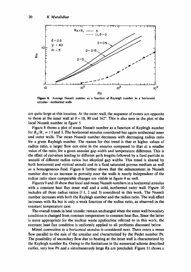
I0 10 2 10 3 Ro Figure 8. Average Nusselt number as a function of Rayleigh number in a horizontal annulus - isothermal walls.
10 4
are quite large at this location. At the outer wall, the sequence of events are opposite to those at the inner wall at 0 = 18, 90 and 162 °. This is also seen in the plot of the local Nusselt number in figure 5.
Figure 8 shows a plot of mean Nusselt number as a function of Rayleigh number for R2/R l = 1"1 and 3. The horizontal annulus considered has again isothermal inner and outer walls. The mean Nusselt number decreases with decreasing radius ratio for a given Rayleigh number. The reason for this trend is that at higher values of radius ratio, a larger flow can exist in the annulus compared to that at a smaller value of the ratio, for a given annular gap width and temperature difference. This is the effect of curvature leading to different path lengths followed by a fluid particle in annulii of different radius ratios but identical gap widths. This trend is shared by both horizontal and vertical annulii and in a fluid saturated porous medium as well as a homogeneous fluid. Figure 8 further shows that the enhancement in Nusselt number due to an increase in porosity near the walls is nearly independent of the radius ratio since comparable changes are visible in figure 4 as well.
Figures 9 and 10 show that local and mean Nusselt numbers in a horizontal annulus with a constant heat flux inner wall and a cold, isothermal outer wall. Figure 10 includes all three radius ratios (1.1, 2 and 3) considered in this work. The Nusselt number increases with both the Rayleigh number and the radius ratio. The wall effect increases with Ra but is only a weak function of the radius ratio, as observed in the constant temperature case.
The overall trends in heat transfer remain unchanged when the inner wall boundary condition is changed from constant temperature to constant heat flux. Since the latter is more appropriate for the nuclear waste application referred to in this work, the constant heat flux condition is uniformly applied to all problems discussed below.
Mixed convection in a horizontal annulus is considered next. There exists a mean flow parallel to the axis of the annulus and characterized by the Peclet number Pc. The possibility of secondary flow due to heating at the inner wall is characterized by the Rayleigh number Ra. Owing to the limitations in the numerical scheme described earlier, very low Pe and a simultaneously large Ra are precluded. Figure 11 shows a

Convection in a saturated porous annulus
I I I I
I0 F ~ 20
21
8~" ~ /D=0 .5 / 4,6
.D=O
D=0.5.~\
t Ro : 500 R2/RI=2=R
4 ~ :03 8 Pr :5
:40
IO =?
i I I I 40 80 120 160 °
Figure 9. wall.
0 Local Nusselt number distribution in a horizontal annulus - constant flux inner
[ | Io
i i i i , , i , i , i i i i i i i I i i i I I I l l I I I I I I I I |
~=0.3 Pr= 5
o o 5 - - = = .
R=3 D=O
, I I I | I I i l l I I I I I I I I i I I I I i L L
~o z io 3 io 4 to ~
Ro
Figure I0. Average Nusselt number as a function of Rayleigh number in a horizontal annulus - constant flux inner wall.

22 K Muralidhar
I0 I I
i, ! I
Pe = I0
i Rt/Ri Ro 2
o I.I 0 I.I 500 3 0 3 500
~ Qe • 0 0
I 2 4 6
Ro
5OO
I00
0 0 0
Figure II.
I I I 8 I0 12 14
z
Inner wall Nusselt number as a function of distance in a horizontal annulus.
plot of the local inner Nusselt number as a function of the axial coordinate z and for various radius ratios and Rayleigh numbers. At Ra = 0, the curve refers to forced flow in an annulus with a radius ratio of 2. For other annulii, the heat transfer behaviour is shown via data points. The general trend is towards large values of Nu at small z and nearly constant value downstream. The fall in Nu with z coincides with the growth in the thermal boundary layer on the heated wall till the latter becomes thick enough to touch the cold outer wall. The temperature profile becomes fully developed at this stage and Nu becomes a constant, equal to the conduction limit. Hence, when R a = 0 , we have, lim~_.~ Nu-+Nuc, the conduction Nusselt numbers Nuc being given in table 1 for different values of R2/R 1.
For Ra > 0, the local Nusselt number curve shifts upwards since heat transfer is now due to the combined mechanisms of forced flow and buoyant secondary flow. There is no sudden change in the structure of flow as one goes from Ra = 0 to Ra > 0. This is because the secondary flow is quite small close to the entrance where the thermal boundary layers are thin. Its effect increases downstream and a fully developed state is attained. This state depends on the Rayleigh number. Hence, for Ra < 500, forced flow dominates free convection over the range 0 < z < 1. The extent of mixed convection depends on the magnitude of Ra and decreases with increasing Ra.

Convection in a saturated porous annulus 23
3.5
3.0
2.5
z 2.0
z 1.5
1.0
I I I I
R2/R~= 2 P e = l O Ra -- 5 0 0
3 . 6 7 5 ~
5~ i i i I Figure 12. Local Nusselt number as a O. 36 72 108 1d.4 180" function of angular coordinate in a hori-
e zontal annulus.
Buoyancy is seen in figure 11 to accelerate the boundary-layer growth and also determine the heat transfer rate when this layer fills the annular gap width. For R2/R 1 = 2, the fully developed Nusselt number is 2.298 at Ra = 100 and 3.94 at Ra = 500. These values are identical to the average Nusselt numbers obtained from two-dimensional analysis of free convection in a horizontal porous annulus (figure 10). Since the flow becomes fully developed over a shorter distance at higher Rayleigh numbers, there is a reduction in computational time in the numerical solution of these problems. Figure 11 also shows that the trends remain unchanged as the radius ratio is varied to 1.1 and 3.
Figure 12 is a plot of the local Nusselt number normalized by the forced convection value as a function of the angular coordinate. The extent of skewness of this graph is a measure of the magnitude of buoyant secondary flow. At small z, this curve is nearly fiat showing that heat transfer is primarily determined by the superimposed velocity in the z direction. At larger values of z, the skewness increases and at z = 10.675, the distribution appropriate for a free convection problem is recovered. Beyond this point, all the heat transfer from the hot wall is transferred to the cold wall and the fluid moving in the axial direction does not pick up additional thermal energy. The stabilized velocity pattern in the annulus (for example, beyond z = 10-675 at Ra = 500 and R2/R ~ = 2) then corresponds to a three-dimensional swirling flow.
5.3 Vertical annulus
Figure 13 is a comprehensive plot of the local Nusselt number on the inner wall as a function of distance for a vertical annulus of aspect ratio AR (= LIAR) = 10. Once again we consider only the constant heat flux boundary condition on the inner wall and a cold isothermal outer wall. Figure 13 is drawn for a radius ratio R2/R t = 2. Curves 1 and 2 are at the free convection limit and due to the presence of insulating top and bottom walls (at z = 0 and AR) the Nusselt number remains finite at z = 0. The general trend is towards a decreasing value of Nu due to the growth of the

24 K Muralidhar
Z
4
3
r r r
Ro
I I 2 I00
3 I
4. I00 5 500
- I - ~ T . . - - . - R 2 / R I = 2
Pe
0 0
I0
I0 I0
. . L _ _ _ _ . _ . a ~ _ _ . t _ _ a . _ _ . L _ Figure 13. Inner wall Nusselt number 2 4 6 8 I0 as a function of distance in a vertical
Z annulus.
thermal boundary-layer on the inner wall. Ra = 1 and Pe = 0 is the conduction limit for the vertical annulus. Curves 3, 4 and 5 are mixed convective flows, though curve 3 (Ra = 1, Pe = 10) is barely affected by buoyancy and can be treated as the forced convection limit. For Pe > 0, the Nusselt number for small z is large and can raise the average value for the annulus as a whole. To compare the vertical annulus with a horizontal one, we note the following. The heat transfer problem including buoyancy remains two-dimensional in the vertical geometry while it is three-dimensional for the horizontal one. The Nusselt number in the latter problem approaches the free convection limit independent of superimposed flow. In a vertical annulus the axial flow is itself modified and the limit reached at large z depends on both Pe and Ra.
It is seen in figure 13 that the Nusselt number variation for Ra = 100 and Pe = 0 (curve 2) corresponds closely to that for Ra = 1 and Pe = 10 (curve 3) except near z = 0. It may then be concluded that velocities generated due to buoyancy at Ra = 100 are of a magnitude comparable to mean flow at Pe = 10. Hence, at Ra = 100, Pe >> 10 would make forced convection predominant and at Pe = 10, Ra>> 100 would make free convection the primary mechanism of heat transfer.
• Local Nusselt numbers as a function of z in mixed convective flow for R2/RI = 1.1 and 3 are shown in figures 14 and 15 respectively. The conclusion that increasing the radius ratio for a given gap width increases Nus~elt number continues to hold at these radius ratios as well.
Figure 16 shows a plot of average inner Nusselt number of the entire vertical annulus as a function of Rayleigh number, for three radius ratios. Two sets of curves are shown for Pe = 0 and Pe = 10. The ihcremental change in Nu is about the same for all radius ratios and both Peclet numbers, for a given change in Ra. Hence the percentage change in heat transfer due to buoyancy drops at higher Peclet numbers. The finite jump in Nu between Pe = 0 and Pe = 10 is primarily related to the

6
5" 4 Z
Convection in a saturated porous annulus
I I I I I
R 2 / R I = I.I Ro Pe
I I 0 0 0
2 I00 I0
3 500 I0
I0
e
I I I I I
2 4 6 8 I0
Z
25
Filcire 14. Inner wall Nusselt number as a function of distance in a vertical annulus.
Z
i i
R 2 / R I = 3 RO Pe
I I 0 0 0
2 ~oo ~o
3 5 0 0 I0
• 0 I0
I I I I I
2 4 6 8 I0
Z
FiBre 15. Inner wall Nusselt number as a function of distance in a vertical annulus.
Z
4
0
I
AR = I0
Pe = I0
Pe = 0
I I I0 I 00
Ro
3 Z
!
I 0 0 0
Figure 16. Average Nusselt number of a vertical annulus as a function of Rayleigh number.

26 K Muralidhar
fundamental change in flow pattern between free and mixed convective flow. This jump remains finite even if Pc is only marginally greater than zero. At Pc = 0, a recirculatory pattern appears in the annulus. For Pc > 0, this pattern is destroyed, being replaced by thin boundary layers near the inlet and hence large heat transfer rates. The size of the jump can be expected to reduce for large aspect ratios since the enhancement in heat transfer described above is restricted to small values of z.
In the configuration of the vertical annulus described above, buoyancy aids mean tlow and there is an increase in heat transfer rate from the heated wall over the forced convection values. It is also possible to consider external flow in a direction parallel to the gravity vector and buoyancy opposing this motion. Results of this calculation are not presented here. This is because the solution is seen to be very sensitive to the exit flow boundary condition (z=0, here) and a gradient condition such as d T/Oz = a~b/az = 0 is no longer applicable in this disturbed region. This problem needs further attention.
5.4 Limiting case of an isolated cylinder
We investigate below the possibility of heat transfer in an annulus reaching the limit of an isolated cylinder at a radius ratio R2/R~ = 3. The free convection problem for a vertical and a horizontal cylinder is solved by an energy-integral method in the appendix. For forced flow parallel to the axis of a cylinder, heat transfer is governed by the equation,
OT/Oz = (1~Pc)IT,, + (l/r) T,],
and boundary conditions, z =0, T = 0 , r = 1, T,= - 1, r ~ oo, T ~ 0 . It is assumed here that Tzz in the diffusion term is negligible. The radius of the cylinder is used as the characteristic linear dimension. The temperature distribution is invariant to the modified coordinate z/Pc. This is a feature shared by all forced flow problems in which axial conduction is neglected, z/Pc is independent of the choice of the characteristic linear dimension. The analytical solution of the problem stated above is obtained by Fourier transform as,
~; g I- (,/P+ -1 T(r,:)= N-7 .o( ,r)expt-ll::/PelLJ ° exprn::'l.o ,l)dz'Jdlt
where Ro(fl, r) = Jo(fl r) Yl (fl) - J l (fl) Yo(flr),
N(fl) = J~(fl) + Y21(fl),
and J and Y are Bessel functions of the first and second kind. The wall Nusselt number is evaluated at l /T0 , z).
The analytical solution given above is plotted in figure 17. It is seen that Nu monotonically decreases with z for a given Peclet number. This can be explained in terms of the unrestrained growth of the thermal boundary layer into the external fluid. Figure 17 also shows the numerical solution for forced flow in an annulus for two different Peclet numbers. The radius ratio R2/R l is 3 and the outer wall is kept cold relative to the inner wall. For small z, the thermal boundary-layer thickness is smaller than the annular gap width and the isolated cylinder solution partially matches the annulus solution. However, for larger values of z in the annulus, Nu reaches a steady value, the temperature profile is fully developed and heat is directly transferred

Convection in a saturated porous annulus 27
Z
' I w i i , [ ) )
) Qnoly t ico l
" c , j • Pe= I R = / R ! = 3 . : p P e : ! O ~ t R z / R l = 3 ( c o l d outer wol,) o P e = I O } (od iobo t i c ou ter
wo l l )
I ~ : ° ° ° " °
° ~ ' ~ ~ . ° ~ • o
Nu(®) = 0.135"---.--.--= i
• I I I0 I0 = I0 ~
z / P e
Forced convection in an annulus compared with an isolated cylinder. Figure 17.
from the hot to the cold wall. Hence, it is clear that the annulus with the boundary conditions chosen will not represent flow over an isolated cylinder.
In the isolated cylinder problem, heat transfer occurs from the wall to the fluid with the heat flux being zero at the outer edge of the thermal boundary-layer. This suggests that the outer wall of an annulus be kept adiabatic to model flow over a single cylinder. The solution of this problem is also shown in figure 17. The continuous fall in Nu required by the isolated cylinder is reproduced here. Hence this pair of boundary conditions for an annulus may be treated as an alternative to modelling forced and mixed convective flows over isolated cylinders.
Figure 18 compares the local Nusselt number distribution in free convection over the inner cylinder of a horizontal annulus with that of a single cylinder. The annulus Nusselt number is consistently higher than the cylinder values showing that the presence of a cold neighbouring wall provides an efficient mechanism for heat removal. Figure 19 shows a similar comparison for a vertical annulus (radius ratio = 3) with a vertical cylinder. Once again the annulus Nusselt numbers are consistently higher
z 4
I I I I
Ro = IOOO
0 I I I I 0 . / 5 2 . / 5 3 ~ / 5 4 ~ / f i
0
Figure 18. Comparison oflocal Nussclt number as a function of the angular coordinate for a single cylinder and a horizontal annulus.

28
16
12
K Muralidhar
I I I
Ro = I000 Pe = 0
z 8
R2/R I = :3
I I I I 0 2 4 6 8 I0
Figure 19. Comparison of local Nusselt number as a function of distance for a single cylinder with a vertical annulus.
than the cylinder values. For an isothermal heated inner wall, Prasad & Kulacki (1984) suggest that the isolated cylinder limit is reached in free convection only at a radius ratio of 26. Figure 20 is a plot of the mean Nusselt number as a function of Rayleigh number for free convection in both horizontal and vertical configurations. For the vertical annulus, the aspect ratio AR = 10. The isolated cylinder is seen again to be uniformly below the annulus Nusselt numbers for both configurations.
Despite large differences between the free convective behaviour of annulii and single cylinders, there is reason to believe that mixed flow past single cylinders can be treated
l ' ,~ i I I
,°
8 R2/RI='~ IH)
~ _ . o . _ . --..o--- \ CYL{V)
2; CYL(H)
0 I I I I0 I02 103 104
Ra
Figure 20. Comparison of average Nusselt number as a function of Raylbigh number for a single cylinder with Nu fQr an annulus.

Convection in a saturated porous annulus 29
via annulii with moderate radius ratios (say, 3) with the outer wall kept insulated. The basis for this is the following. At the limit of forced flow it has already been demonstrated above that the annulus approximation is adequate. In mixed flow, the thermal boundary-layers are thin near the entrance and buoyancy effects are small. At larger distances, the boundary-layer touches the outer wall and since no heat transfer can occur here, the fluid temperature continuously rises in the annular gap width. Hence, the temperature equalization in the fluid once again leads to small buoyancy effects. For an isolated cylinder, temperature equalization occurs due to increasing boundary-layer thickness which reduces the proximity of the cold fluid region to the heated wall. U s i n g the annulus model for a single cylinder, mixed convection results are
presented here for both vertical and horizontal geometries. Figure 21 shows the local Nusselt number variation with z for a vertical annulus. The solution for the cold outer wall is also shown for comparison. The drop in Nu due to an adiabatic outer wall is clearly visible in this graph. Figure 22 shows the mean Nusselt number variation for a vertical annulus with aspect ratio AR = 10, as a function of Rayleigh number.
Figure 23 shows results for mixed convection in a horizontal annulus for different values of z and Ra. The decay of buoyancy effects is visible here as well, since the Nu-z curves for Ra > 0 tend to merge with the curve for Ra = 0 for increasing values of z. At intermediate values of z, buoyancy does enhance heat transfer. A measure of this enhancement is the skewness in the local Nusselt number at given location z, as a function of 0. This is shown in figure 24. The skewness (and the swirl component of flow) decrease with distance and at z = 10 and Ra = 500, the flow has recovered its uniformity. Beyond z = 10, Nu would continuously fall in magnitude as seen in figure 17.
16 I I I
Pe = I0
R2 /R I = 3
12j co ld woll
o = 5 0 0 ] Ro ~:00 l adiabatic • Ro
Q Ro
+I | I I
0 2 4 6 8
Figure 21. Local Nusselt number as a function of distance in mixed
10 convection in a vertical annulus.

30 K Muralidhar
6 i
5
4
z3
2
I
o
Pe = I 0 Rz/RI=3
I
AR = I0 I !
adiabatic
i I i I0 IO 2 103
Ra
Figure 22. Average Nusselt number as a function of Rayleigh number in mixed convection in a vertical annulus.
- - I z
ih
0
I I I I I I
P e = I 0 R2/RI=3
I I I I I I 2 4 6 8 I0 12
z
Figure 23. Nasselt number as a function of distance in mixed convection in a horizontal annulus.
IF
I I I I
R2/R I = 3 , P e = l O
500 z
4
I I I I ~ / 5 2 ~ / 5 3 ¢ / 5 4 ~ / 5
O "It
Figure 24. Local Nusselt number as a func- tion of the angular coordinate in mixed convection in a horizontal annulus.

Convection in a saturated porous annulus 31
5.5 Flow patterns
Both horizontal and vertical annulii filled with a homogeneous fluid would show a variety of flow phenomena as the Rayleigh number is increased. Some of these are multi-ceUular convection, vortex shedding and turbulence (for example, see Rao et al 1985). These are related to the inertial effects in the fluid. In a porous annulus, inertial effects in the fluid phase are seen to be small for most Darcy numbers encountered in practice. Hence it is to be expected that unicellular convection will prevail for all Raylcigh numbers for which inertial effects are small. Typical streamline patterns and isotherms in a horizontal annulus are shown in figure 25a. A sketch of velocity vectors in mixed convection is shown in figure 25b for a vertical annulus and figure 25c for a horizontal annulus.
Caltagirone (1976) has noted a systematic discrepancy between measured data and computations using Darcy's law for a horizontal annulus with a constant temperature on the inner wall. This has been reproduced in figure 26. For Rayleigh numbers beyond the conduction regime (Ra > 10), the experimental data is consistently above the numerically generated curve. The difference has been traced to the possibility of instability and in particular the onset of three-dimensional flow from an initially two-dimensional base flow. Increased levels of heat transfer are then expected to occur due to small perturbations being sustained by the mean flow. Caltagirone's experiment consists of an annulus whose inner and outer radii are 4 and 8 cm respectively, packed with glass beads of size 3 to 4 mm.
It is proposed here that the discrepancy seen in figure 26 arises out of the porosity variation near the solid boundary rather than three-dimensional effects. In the experiments referred to above, each glass bead occupies 10% of the annular gap width allowing wall porosity to become much larger than the mean porosity. Laboratory experiments conducted in this work with a larger annulus confirm this trend.
5.6 Experiments with a horizontal annulus
In the present study, experiments were performed in a horizontal annulus with an inner radius of 10cm, outer radius of 15"2cm and with 3 and 6mm diameter glass balls. The porosity of the system filled with only 3 mm balls was 0.357 and hence the permeability K = 0.675 x 10 -s m 2. When filled with 6mm balls, the porosity was 0"383 and the permeability K = 2.95 x 10-am 2. These values are small enough for inertial effects to be absent but the bead diameter of 6 mm is expected to display wall porosity effects. The saturating liquid was water in all the runs. The inner cylinder was arranged to provide a constant heat flux boundary condition. Measurements were all made at steady state, typically after 12 h.
The aspect ratio of the test cell was 12 and hence the flow was close to two dimensional. The inner cylinder was made of a brass sheet, heated from the inside by strip heaters. The outer wall was cooled by water carried in copper coils to maintain an isothermal boundary condition. Temperature was measured by 30 gauge copper/ constantan thermocouples via a multi-channel data acquisition system. At steady state, ten data points were acquired at 5 min intervals and averaged. Fluid properties were evaluated at the arithmetic mean of wall temperatures. The bulk mean thermal conductivity of the annulus was measured at very low heating rates and was found to be close to the convectional rule of mixtures formula, km= ekf + (1 - e)ks, where f , s and m stand for fluid, solid and medium respectively. The characteristic

32 K Muralidhar
isotk nlines
(a)
71111 IITII Ro:°
I
lib Ro>O
TIh imi|
Tth ,|ii
IIII
(b)
Ra>O I
I (c)
Figure 25. (a) Streamline pattern and isotherms in a horizontal annulus. (b) Velocity vectors in forced and mixed flow in a vertical annulus. (c) Velocity vectors in forced and mixed flow in a horizontal annulus.

Convection in a saturated porous annulus 33
4
3
:0
7 2
) , ) " | Q',
5
• .* •°
) ) I I ~ -_ Figure 26. Comparison of experimental data I0 30 100 3 0 0 with the Darcy model (from Caltagirone
RO (1976).
permeability was chosen as the average value prevailing in the annulus. Error analysis including scatter in temperature data and uncertainty in fluid properties revealed that the Nusselt number was accurate to within 5.5% and the Raylcigh number to within 6.5% of the measured values.
The experiments were initially set up to study the effect of variable porosity and permeability on heat transfer. To this end, one half of the annulus, between RI < r < (R1 + R2)/2 was filled with beads of uniform diameter and the outer half, (R~ + R2)/2 < r < R 2, with beads of a different but also uniform diameter. We identify as case C1, an arrangement where 3 mm beads lie adjacent to the heated wall and 6 mm beads near the cold wall. The second case C2 has the opposite arrangement of 6 mm beads near the heated wall and 3 mm beads near the cold wall. Figures 27 and 28 show the mean Nusselt number as a function of Rayleigh number for the heated wall. Both experimental data and numerical predictions are shown in these figures. It can be seen that the heat transfer characteristics of the systems CI and C2 are different and this has implications in practice. For example, the cracking of earth near the buried waste canister will result in case C2, leading to a higher Nusselt number, lower wall temperature but larger fluid movement.
Figures 27 and 28 show that the comparison between analysis and experiments is satisfactory. This is more so in case 1, while in case 2, a systematic divergence of
I0
J Z
i i V I I W I I I ) i J I ~ I I I ~ I I I I I I 1
cose C I L o numer ica l . o * ° ~- • e x p e r i m e n t • o
o" 0 e
0
0
0
e o
o
I i i , i [ * , i l i i i , , , , , I ~ J l I * i l
I0 10 2 10 3 I0 4 Ro
Figure 27. Average Nussclt number as a function of Rayleigh number for case 1,

34 K Muralidhar
I0
z
w t • • ~ , , , | , , i i w I l l I I I I l I , 1 ~
O • O
case C 2 • • o
o numer ica l • o
• e x p e r i m e n t ° o
O
6 0
0
I : J I J • , . , I
I0 I0 2
Figure 2&
%
o"
: , I i . . , . I . i • • • , . ,
i0 3 0 4 Ro
Average Nussclt number as a function of Raylcigh number for case 2.
experimental data is seen as Ra is increased. The origin of this discrepancy is explained here in terms of increased wall porosity leading to channelling of flow. In case 1, the 3ram beads lie mext to the heated wall and each bead occupies a fraction 30/516 (6%) of the annular gap width. In case 2, this fraction is 12% and the possibility of channelling becomes important.
5.7 Duration of transients
The duration of transients in an annulus depends on the distance to be covered by the disturbance before steady state is reached and on the diffusion coefficients. For flow, this distance is of the order of the pore diameter and hence is small. It is assumed below that the medium adjhsts its flow field instantaneously and hence flow equations remain unchanged during the transient process. The characteristic distance to be covered by a thermal disturbance is of the order of the annulus gap width and hence this duration is finite. For free convection, the transient thermal energy equation is,
T, + u.VT = V 2 T. (20)
For a horizontal annulus, (20) reduces to (9) with z replacing z/Pe. Hence transient convection in a horizontal annulus is described by figure 11. For a vertical annulus, the energy equation remains unchanged, but the flow equation is different. The marching technique described in this paper can be used to solve these equations as well. Figure 29 shows Nusselt number as a function of ~ for a vertical annulus. Both figures 11 and 29 show that z is of order unity at the conduction limit and may be as small as 0.1 at Ra = 500. For the nuclear waste application, ~ = 1 translates to t = 2 years, for AR= lm and a= 15.6 x 10-gm2/s.
For transient forced convection in an annulus, the governing equations reduce to that for temperature alone,
7",+ Pe T~= [T.+(1/r) T,].
The initial and boundary conditions are,
• =0, T=O,
(21)
z =0, T=O,

Convection in a saturated porous annulus 35
I 1 I
Figure 29. annulus.
:3 Z
Ro Nu (m)
5 0 0 3.56
Ro( in i t io l ) = 0
I I i
0.1 0.3
I 00 2.106
0 1.4427
I i i i
0 0.5 0.7 "Z"
Transient free convective Nusselt number as a function of time in a vertical
r=R1, T, = - 1,
r=R2, T = 0 .
The solution of (21) is,
T(r,z)= Rl ln(R2/r) + ~ c,R(A,,r)exp(--2~), 0~<~<(z/Pe) n = l
and steady state for z > z/Pe. The quantities c,, R and A n are given in (19a). The Nusselt number variation with z/Pe and z in forced flow is shown in figure
30. Clearly transients exist for a much shorter time period for large values of Pe. The kink in the curves for given values of z/Pe arises due to neglecting T==, the axial diffusion term in (21).
Conclusions
The conclusions arrived at in this study are summarized below.
(i) Over the range of parameters studied here, inertial and viscous effects in the fluid phase are negligible. However, considerable deviation can occur from Darcy behaviour due to increased levels of porosity in the near wall region. (ii) Heat transfer rates increase with increasing radius ratio for a given gap width. (iii) The isolated cylinder limit is not reached at R2/R1 = 3 in the fre¢ convection regime. However, in forced and mixed flow regimes, this limit can b¢ modelled as flow in an annulus with an adiabatic outer wall.

36 K Muralidhar
z
5
4
3
2 -
I I
o 0.2 0.4
! I
R2/RI = 2
. . . , , , z / P e = 0.1
0.2
0.4
1.0
I I
0.6 0.8
2"
Figure 30. Transient forced convective I.O Nusselt number as a function of time in an annulus.
(iv) Thermal transients can exist for a long time in flows at low Rayleigh and Peclet numbers and will have to be included in a detailed analysis. This period reduces at higher values of Ra and Pe.
Appendix A
Effect o f viscous friction on free convective heat transfer f rom a cylinder
While the viscous effects in a porous medium are of the order of Da, they are O(Da ~) in the region just near the impermeable wall. The effect of this viscous layer on heat transfer can be determined by performing a boundary layer analysis where the outer flow is simply Darcian. Hence the problem reduces to a viscous layer overlaid by a Darcian boundary layer. This model is shown in figure A1.
Outer f low analysis
Using boundary layer approximations such as (~/00) << (O/Or) for a horizontal cylinder and (O/~z)<< (a/Or) for a vertical cylinder, the following equations can be derived.
Horizontal: (rv), = r Ra T, sin 0,
(vT)o + (urT), = (rT,),. (A1)
Vertical: w = Ra T,
(uTr), + (wTr)~ = (rT,),. (A2)
The boundary conditions are,
r = 1, T, = - 1 (constant heat flux),
r = l + ~ , T = O .

Convection in a saturated porous annulus 37
oo I ,
I: °l/!
L_ ] ---~v~: ~ r Figure AI.
boundary. Model of flow near an impermeable
The radius of the cylinder has been used here as the characteristic linear dimension. A temperature profile of the form, T = ( 6 / 2 ) { 1 - [ ( r - 1 ) / 6 ] } 2 satisfies the two boundary conditions automatically. Clearly, the wall temperature is 6/2 and the local Nusselt number, Nut = 2/6. This profile is used to determine velocity from the momentum equation in terms of 6. 6 in turn is determined from the integral version of the energy equations given in (A1) and (A2). Since the net convective heat flux normal to the cylinder is zero, terms such as (urT), in (A 1) and in (A2) do not contribute to the integral. The following results are then obtained.
Horizontal:v=Rasi~nO{[r3-(l+6)3 1 1 (1 + 6) [ r2_ (1 + 6)2]} r 3 2 6 '
f;+~F(r,f,O)dr=O,
where F = v[r - (1 + 6)]2/26.
Vertical: w =(Ra6/2){l - [ ( r - 1)/6]} 2,
663 + 64 = (120/Ra)z.
The 6-equation can be solved for each 0 and z and the local Nusselt number calculated as 2/6. In this work, 6 has been obtained from a Newton-Raphson scheme for root extraction. Results of this analysis are presented in figures 18 and 19 of the text.
Inner flow analysis
With reference to figure A1, the viscous sublayer thickness 6v is assumed to be much smaller than the Darcian boundary-layer thickness 6. The maximum velocity Uo is chosen as the tangential velocity component in Darcian analysis evaluated at the wall (r = 1). Within 6v, the following conditions are expected to prevail. (i) Constant radial heat flux; (ii) constant shear stress. In the cylindrical coordinate system, this gives,
T = Tw+ ln[(l +6v)/r],
(v,w)=(Vo,Wo)'[(r-1)/6v], 1 < r < ( 1 +6v). (A3)

38 K Muralidhar
T,~ is the wall temperature calculated from the outer flow (= 8/2). In (A3) it remains to determine 6v. The Brinkman equations in the thin region next to the wall are given below.
Horizontal: p, Ra T cosO- u + (Da V2/8)u =O -] (A4)
- (po/r) + Ra Tsin 0 - v + (Da/e)V2 v = 0_J •
In (A4), we set the radial velocity u ~ 0 and solve for p as,
p = - r Ra T cos 0 + f(0),
where f is an undetermined function. This is substituted in the second equation of (A4) to yield
(1/r) f ' - v + (Da/e ) V2 v = O.
This equation can be evaluated at the edge of the viscous layer as [1/(1 + ~v)] f ' - Vo = 0. Hence f ' = (1 + 6~)Vo. The quantity V2v can be evaluated using the assumed profile for v. Again (A4) is required to hold only in the integral sense, i.e 6~ satisfies
f~+6v[( f ' / r ) -v-(Da/e)V2v]dr=O.
This gives/i v = Da~/e, using the approximation, In (1 + 6~)~ 6v.
Vertical: The z-component momentum momentum equation is,
- w + Ra T+(Da/e)V2w =0 . (A5)
Using the profiles of w and T given above and integrating (A5) as S~ +~v dr gives the intermediate equation,
~ [ ( R a To/uo) - ½] = Da/e
and hence
6v = (Da/e)L
The expressions for $v are identical for the horizontal and vertical cylinders. This is because of the simple model assumed for u and T within the viscous layer.
A comparison of the Darcy and Brinkman (local) Nusselt numbers for the horizontal annulus is given in table A1 and for the vertical annulus in table A2. We assume Da = 10 -6 and ~ = 0.1. The difference between the Nussclt numbers of the two models
is seen to be quite small.
Table AI. Comparison of Nu~ using Darcy and Brinkman models - horizontal cylinder.
Ra = 500 Ra = 2000
0 Nu(D) Nu(B) Nu(D) Nu(B)
(H 6-012 5'855 9"451 9.069 (~5 5"934 5-780 9-327 8-954 1 5-687 5-547 8-936 8-594 1"5 5"269 5.148 g.274 7"979

Convection in a saturated porous annulus 39
Table A2. Comparison of Nu I using Darcy (D) and Brinkman (B) model - vertical cylinder.
Ra = 100 Ra = 2500
z Nu(D) Nu(B) Nu(D) Nu(B)
0.5 4.76 4-66 13-11 12"38 2 3-13 3"08 8"43 8-12 4 2-55 2-52 6.78 6"58
10 1'95 1.93 5.1 4.98
List of symbols
AR A,C Cp D Da d dp F g,g
h km
k K L Nut
N u f
Nu
/~,p Pe Pr q Q
aspect ratio = LIAR; grid generation parameters; specific heat of the fluid; wall porosity parameter; Darcy number = K/AR; average pore diameter; bead diameter; Forschheimer parameter; acceleration due to gravity and gravitational acceleration vector, respectively; heat transfer coefficient = q/[ T(R1 ) - T(R2)]; equivalent thermal conductivity of the porous medium = ek (fluid)+ (1 - 5) k(solid); unit vector parallel but opposite to the gravity vector; permeability of the porous medium; height of the vertical annulus; local Nusselt number
= ( - ~ , = , , ) / R 1 In ~-~ for an isothermal inner wall,
= (1/T)(r = R t ) for constant flux inner wall;
forced convection Nusselt number = value of Nut under forced flow conditions; average Nusselt number
= AR Nut(z)dz for a vertical annulus,
'fo =~- Nut(O) dO, for a horizontal annulus;
static and modified pressure, p = ~ + pogZ; Peclet number = #AR/e; Prandtl number, v/e; heat flux on inner wall; source term in grid generation equations;

40
R R 1 , R 2 r, 0, z
AR Ra Sign (x) t
T AT
tl
u,/3, W
X, y, Z
Z 0t
?
P
# v
,[
V
Subscripts
f m
H,C !
lo r,O 0
K Muralidhar
radius ratio, R2/Rt; inner and outer radii of the annulus; cylindrical coordinates - 0 measured from the gravity vector for a hori- zontal annulus; not applicable for a vertical annulus, z parallel to cylinder axis; R2-RI characteristic dimension; Rayleigh number = gflA T KAR/v~; = l w h e n x > 0 a n d = - l w h e n x < 0 ; time; temperature; characteristic temperature, T n - Tc (isothermal boundaries), qAR/km (constant flux inner wall); velocity vector; velocity components in r, O, z directions, respectively; characteristic velocity at inlet plane of the annulus; Cartesian coordinates appropriate for a general heat transfer problem, with Z the absolute vertical coordinate; distance measured parallel to k; km/pCp, thermal diffusivity; volumetric expansion coefficient; wall porosity parameter; boundary-layer thickness; mean porosity and local porosity, respectively; fluid density; stream function; dynamic viscosity of the fluid; kinematic viscosity of the fluid; transformed coordinates in the radial direction; (dr//dr)2; dimensionless time = ott/AR2;
(0, 0 0) gradient operator \ dx Oy d Z / or \~r rOO'dz "
forced convection value; medium; hot and cold; local value on inner wall; local value on outer wall; partial derivatives, (O/Or) and (0/00) respectively; free stream, cold or reference value.
References
Beavers G S, Sparrow E M 1969 Non-Darcy flow through fibrous porous media. ASME J. Appl. Mech. 136:71 !-714
Bear J 1972 Dynamics of fluids in porous media (Amsterdam: Elsevier) Benenati R F, Brosilow C B 1962 Void fraction distribution of a bed of spheres. AIChE J. 8:359-361

Convection in a saturated porous annulus 41
Caltagirone J 1976 Thermoconvective instabilities in a porous medium bounded by two concentric horizontal cylinders. J. Fluid Mech. 76:337-362
Chapman N A, Mckinley I G 1987 The geologic disposal of nuclear waste (New York: John Wiley} Kimura S 1989a Transient forced convection heat transfer from a circular cylinder in a saturated porous
medium. Int. J. Heat Mass Transfer 32:192-195 Kimura S 1989b Transient forced and natural convection heat transfer about a vertical cylinder in a porous
medium. Int. J. Heat Mass Transfer 32:617-620 Kumari M, Nath G 1989 Non-Darcy mixed convection boundary layer now on a vertical cylinder in a
saturated porous medium. Int. J. Heat Mass Transfer 32:183-187 Lauriat G, Prasad V 1989 Non-Darcian effects on natural convection in a vertical porous enclosure. Int.
J. Heat Mass Transfer 32:2135-2148 Muralidhar K 1989 Mixed convection flow in a saturated porous annulus. Int. J. Heat Mass Transfer 32:
881-888 Muralidhar K, Baunchalk R A, Kulacki F A 1986 Natural convection in a horizontal porous annulus
with a step distribution in permeability. J. Heat Transfer 108:889-893 Muralidhar K, Guceri S I 1986 Comparative study of two numerical procedures for free convection
problems. Num. Heat Transfer 9:631-638 Muralidhar K, Kulacki F A 1988 Non-Darcy natural convection in a saturated horizontal porous annulus.
J. Heat Transfer 110:133-139 Nakayama A, Koyama H, Kuwahara F 1989 Similarity solution of non-Darcy free convection from a
non-isothermal curved surface in a fluid saturated porous medium. J. Heat Transfer 111:807-810 Ozisik M N 1980 Heat conduction (New York: John Wiley) Prasad V, Kulacki F A 1984 Natural convection in a vertical porous annulus. Int. J. Heat Mass Transfer
27:207-219 Rao Y, Miki Y, Fukuda K, Takata Y, Hasegawa S 1985 Flow patterns of natural convection in horizontal
cylindrical annulii. Int. J. Heat Mass Transfer 28:705-714 Vafai K 1984 Convective flow and heat transfer in a variable porosity media. J. Fluid Mech. 147:233-259 Vafai K, Tien C L 1981 Boundary and inertia effects of flow and heat transfer in porous media. Int. J.
Heat Mass Transfer 24:195-203