a review of gas-cooled reactor concepts for sdi applications · a review of gas-cooled reactor...
TRANSCRIPT

&£&I0/C>?62. SANDiA REPORT SAND87-0558 • UC-522 Unlimited Release Printed August 1989
A Review of Gas-Cooled Reactor Concepts for SDI Applications
A. C. Marshall
Prepared by Sandia National Laboratories Albuquerque, New Mexico 87185 and Livermore, California 94550 for the United States Department of Energy under Contract DE-AC04-76DP00789
'Cm STATEMTOT
for public release; Distribution Unlimited
PLEASE RETURN TO:
! BMD TECHNICAL INFORMATION CENTER BALLISTIC MISSILE DEFENSE ORGANIZATIO
i >7100 DEFENSE PENTAGON WASHINGTON D.C. 20301-7100
SF2900Q(8-81) Ü02077

Issued by Sandia National Laboratories, operated for the United States Department of Energy by Sandia Corporation. NOTICE: This report was prepared as an account of work sponsored by an agency of the United States Government. Neither the United States Govern- ment nor any agency thereof, nor any of their employees, nor any of their contractors, subcontractors, or their employees, makes any warranty, express or implied, or assumes any legal liability or responsibility for the accuracy, completeness, or usefulness of any information, apparatus, product, or process disclosed, or represents that its use would not infringe privately owned rights. Reference herein to any specific commercial product, process, or service by trade name, trademark, manufacturer, or otherwise, does not necessarily constitute or imply its endorsement, recommendation, or favoring by the United States Government, any agency thereof or any of their contractors or subcontractors. The views and opinions expressed herein do not necessarily state or reflect those of the United States Government, any agency thereof or any of their contractors.
Printed in the United States of America. This report has been reproduced directly from the best available copy.
Available to DOE and DOE contractors from Office of Scientific and Technical Information PO Box 62 Oak Ridge, TN 37831
Prices available from (615) 576-8401, FTS 626-8401
Available to the public from National Technical Information Service US Department of Commerce 5285 Port Royal Rd Springfield, VA 22161
NTIS price codes Printed copy: A07 Microfiche copy: A01

Accession Number: 2077
Publication Date: AugOl, 1989
Title: Review of Gas-Cooled Reactor Concepts for SDI Applications
Personal Author: Marshall, A.C.; Brockman, J.E.; Chu, M.S.Y.; et al.
Corporate Author Or Publisher: Sandia National Laboratories, Alberquerque, NM 87185 Report Number: SAND87-0558
Descriptors, Keywords: Heat Transfer Nuclear Reactor Application Space Power Multimegawatt Concept Mass Weight Risk NERVA
Pages: 090
Cataloged Date: Apr 17, 1990
Contract Number: DE-AC04-76-DP00789
Document Type: HC
Number of Copies In Library: 000001
Original Source Number: DE89-016962
Record ID: 21009
Source of Document: NTIS

SAND87-0558 Distribution Unlimited Release Category UC-522 Printed August 1989
A REVIEW OF GAS-COOLED REACTOR CONCEPTS FOR SDI APPLICATIONS
A. C. Marshall
Space Power Systems Studies Division Sandia National Laboratories
Albuquerque, New Mexico 87185
ABSTRACT
We have completed a review of multimegawatt gas-cooled reactor concepts proposed for SDI applications. Our study concluded that the principal reason for considering gas-cooled reactors for burst-mode operation was the potential for significant system mass savings over closed-cycle systems if open-cycle gas-cooled operation (effluent exhausted to space) is acceptable. The principal reason for considering gas-cooled reactors for steady-state operation is that they may represent a lower technology risk than other approaches. In the review, nine gas-cooled reactor concepts were compared to identify the most promising. For burst-mode operation, the NERVA (Nuclear Engine for Rocket Vehicle Application) derivative reactor concept emerged as a strong first choice since its performance exceeds the anticipated operational requirements and the technology has been demonstrated and is retrievable. Although the NERVA derivative concepts were determined to be the lead candidates for the Multimegawatt Steady-State (MMWSS) mode as well, their lead over the other candidates is not as great as for the burst mode.
IJJUU.; £ ,j; •. -,. ^uiüg,

NOTICE: This work was prepared for the Strategic Defense Initiative Space Power Office's Independent Evaluation Group (IEG).
11

SAND87-0558
A REVIEW OF GAS-COOLED REACTOR CONCEPTS FOR SDI APPLICATIONS
Edited by A. C. Marshall
Printed: February 1989
Contributors and Contributing Authors:
J. E. Brockmann M. S. Y. Chu L. O. Cropp V. J. Dandini D. Dobranich M. W. Edenburn D. R. Gallup S. L. Hudson A. C. Marshall W. H. McCulloch R. E. Pepping D. J. Rader F. V. Thome F. J. Wyant
Other Contributors:
S. V. Asselin IEAL J. W. Hockert IEAL G. B. Varnado IEAL
J. M. Smith NASA LeRC A. Juhasz NASA LeRC B. McKissock NASA LeRC
ill

CONTENTS
Section £ase
ACKNOWLEDGMENTS xü
1. EXECUTIVE SUMMARY 1
1.1 Background 1 1.2 Burst-Mode System Studies 1 1.3 MMWSS-Mode System Studies 1 1.4 Concept Review Approach 2 1.5 Burst-Mode Ranking 2 1.6 MMWSS-Mode Ranking 3 1.7 Study Limitations 4 1.8 Changes from the Preliminary Document — 5
2 INTRODUCTION 6
2.1 Background 6 2.2 Concepts Investigated 6 2.3 Study Limitations 8
3. REVIEW APPROACH 10
3.1 System Studies 10 3.2 Gas-Cooled Reactor Concept Studies 10
4. SYSTEM STUDY RESULTS 12
4.1 Burst Mode 12 4.2 MMWSS Mode 12
5. COMPARISON OF GAS-COOLED REACTOR CONCEPT MASSES 14
5.1 Mass Study Ground Rules 14 5.2 Burst-Mode Mass Estimates 15 5.3 MMWSS-Mode Mass Estimates 17
6. BURST-MODE CONCEPT RANKING 19
7. MMWSS-MODE CONCEPT RANKING 23
8. A NOTE ON BIMODAL REACTORS 25
9. CHANGES FROM THE PRELIMINARY DOCUMENT 26
10. REFERENCES 28
IV

CONTENTS (Continued)
Section Page
APPENDIX A SYSTEM COMPARISON A-l
A. 1 Burst Mode A-2
A. 1.1 Open, Gas-Cooled Reactor System A-5 A.1.2 Open, Hydrogen-Oxygen Combustion
System A-6 A.1.3 Closed Rankine- and Brayton-Cycle
Power Systems A-7 A.1.4 Energy Storage Systems A-7 A.1.5 Thermionic Reactor with Thermal
Storage A-7
A.2 Multimegawatt Steady-State (MMWSS) Mode A-8
A. 2 .1 Rankine System A-ll A. 2. 2 Brayton System A-ll A.2.3 Thermionic System A-12
A. 3 References A-12
APPENDIX B REACTOR CONCEPT DESCRIPTIONS B-l
B.1 Particle-Bed Reactor B-2 B.2 NERVA Derivative Reactor B-2 B.3 Pellet-Bed Reactor B-5 B.4 PLUTO Derivative Reactor B-7 B.5 NERVA/PLUTO Hybrid Reactor B-7 B. 6 UB2 Reactor B-9 B.7 Cermet Reactor B-9 B.8 Wire-Core Reactor B-9 B.9 Foam-Fuel Reactor B-12 B. 10 References B-12
APPENDIX C THERMAL HYDRAULIC METHODS C-l
C. 1 Introduction C-2 C.2 Particle- and Pellet-Bed Reactors C-5 C.3 Prismatic-Core Reactors C-7 C.4 Wire-Core and Foam-Fuel Gas-Cooled
Reactor Concepts C-14 C. 5 References C-19

CONTENTS (Continued)
Section ^^
APPENDIX D MASS STUDIES D_1
D.l Method °-2 D. 2 Burst-Mode Mass Estimates D-3
D.2.1 Pellet-Bed Reactor D-3 D.2.2 PLUTO Derivative Reactor D-3 D.2.3 NERVA/PLUTO Hybrid Reactor D-3 D.2.4 UB2 Reactor D-4 D. 2.5 Cermet Reactor D-4 D.2.6 NERVA Derivative Reactor D-4 D.2.7 Particle-Bed Reactor D-5 D.2.8 Wire-Core Reactor D-5 D.2.9 Foam-Fuel Reactor D-5
D. 3 MMWSS-Mode Mass Estimates D-6
D. 3 .1 Pellet Bed Reactor D-6 D.3.2 PLUTO Derivative D-6 D.3.3 NERVA/PLUTO Hybrid Reactor D-6 D. 3.4 UB2 Reactor D-6 D. 3 . 5 Cermet Reactor • • • D-7 D.3.6 NERVA Derivative Reactor D-7 D.3.7 Particle-Bed Reactor D-7 D.3.8 Wire-Core Reactor D-7 D.3.9 Foam-Fuel Reactor D-8
D. 4 References D-8
APPENDIX E ATTRIBUTE REVIEW E-l
E. 1 Burst Mode E~2
E.l.l Technical Risk E-2 E.1.2 Mass E_4
E.1.3 Safety E_4
E.1.4 Survivability E-4 E.1.5 Reliability E-4 E.1.6 Power E~5 E. 1.7 Operation Time E-5 E. 1.8 Development Cost E-5 E. 1.9 Fabrication Cost E-6 E.1.10 Manufacturability E-7 E.l.ll Controllability E-7
VI

CONTENTS (Continued)
section Paqe
E.1.12 Testability E-7 E.1.13 Volume/Area E-7 E.1.14 R&D Payoff E-7 E.1.15 Effluent E-7 E.1.16 Load Following E-8 E.1.17 Deployability E-8 E.1.18 Operational Life E-8 E.1.19 Safeguards E-8 E.1.20 Initial Operational Capability E-8 E.1.21 Mechanical Compatibility E-8 E.1.22 Modal Shift Time E-8 E.1.2 3 Thermal Compatibility E-8 E.1.24 Strategic Materials E-8 E.1.25 Special Interfaces E-8 E.1.26 Maintenance and Repair E-8 E.1.27 Radiation Compatibility E-8 E.1.28 Environmental Compatibility E-8 E.1.29 Electromagnetic Compatibility E-9 E.1.3 0 Design Change Tolerance E-9 E.1.31 Shared Functions E-9 E.1.32 Upgradability E-9 E.1.33 Quality Assurance E-9 E.1.34 Auxiliary Energy Requirements E-9 E.1.35 Operation and End-of-Life Costs E-9 E.1.36 Life Extendability E-9 E.1.37 Intangibles E-9
E. 2 MMWSS Mode E-9
E.2.1 Technical Risk E-10 E.2.2 Mass E-ll E.2.3 Safety E-12 E. 2 . 4 Development Cost E-12 E.2.5 Fabrication Cost E-13 E.2.6 Strategic Materials E-13
E.3 Attributes and Definitions E-14
E. 4 References E-19
APPENDIX F REVIEW OF POTENTIAL FOR FRIT PLUGGING F-l
F. 1 Introduction F-2 F. 2 The Plugging Issue F-2 F. 3 Discussion F-4
Vll

CONTENTS (Concluded)
Section Page
F.3.1 Aerosol Generation F-3 F.3.2 Aerosol Transport to the Frits F-5
F.3.2.1 Fixed Bed F-6 F.3.2.2 Fluidized Bed F-7
F.3.3 Simple Clogging Models F-7
F.3.3.1 Model 1 F-7 F.3.3.2 Model 2 F-9
F.4 Miscellaneous Observations F-10
F.4.1 Pressure Drops Through Packed Beds .... F-10 F.4.2 Aerosol Deposition In Unprotected
Areas F-ll
F.5 Summary p~io F. 6 References F-12
APPENDIX G ASSESSMENT OF THE NERVA REACTOR G-l
G. 1 Introduction G~2
G.2 Assessment of the NERVA Reactor Tests (D. Dobranich) G~2
G.3 Review of NERVA Test Program (D. R. Gallup) G~4
G.3.1 Kiwi G~4
G.3.2 NRX-A5 G-5
G. 3 . 3 Peewee-1 G~5
G.3.4 NRX-A6 G"7
G.3.5 Nuclear Furnace-1 G_7
G. 3 . 6 Conclusions G~8
G. 4 References G~9
APPENDIX H RETRIEVABILITY OF NERVA REACTOR TECHNOLOGY H_1
Vlll

LIST OF FIGURES
Figure Page
4-1 Comparison of Specific Weights of Multimegawatt Space Power Systems for the MMWSS Mode Assuming 10 MWe Power for 1 Year of Operation 13
5-1 Estimated Masses for 500-MWe Burst-Mode Gas-Cooled Reactors 16
5-2 Estimated Masses for a 10-MWe MMWSS-Mode Gas-Cooled Reactor Assuming 1 Year of Operation 18
A-l Comparison of Specific Weights of Burst-Mode Space Power Systems A-3
A-2 Comparison of Specific Weights of MMWSS-Mode Space Power Systems A-9
B-l Particle-Bed Reactor B-3 B-2 NERVA Reactor B-4 B-3 Particle-Bed Reactor B-6 B-4 PLUTO Reactor B-8 B-5 Cermet Reactor B-10 B-6 Wire-Core Reactor B-ll B-7 Foam-Fuel Reactor Concept B-13
C-l Specific-Power Limits for Burst-Mode, Pellet-Bed Reactor C-5
C-2 Specific-Power Limits for Moderated, Burst-Mode, Particle-Bed Reactor C-8
C-3 Specific-Power Limits for Burst-Mode, Pellet-Bed Reactor C-8
C-4 Specific-Power Limits for Unmoderated, MMWSS-Mode, Particle-Bed Reactor C-9
C-5 Specific-Power Limits for Moderated, MMWSS-Mode, Particle-Bed Reactor C-9
C-6 Specific-Power Limits for MMWSS-Mode, Pellet-Bed Reactor C-10
C-7 Burst-Mode Specific Power for Prismatic-Core Concepts C-13
C-8 MMWSS-Mode Specific Power for Prismatic-Core Concepts C-15
C-9 Specific Power of Wire-Core Reactor in Burst Mode C-16
C-10 Specific Power of Wire-Core Reactor in MMWSS Mode C-17
C-ll Specific Power of Foam-Fuel Reactor Burst Mode C-18
C-12 Specific Power of Foam-Core Reactor in MMWSS Mode C-18
IX

LIST OF FIGURES (Concluded)
Figure Page
F-l Orifice Control of Cooler Flow F-3 F-2 Rhenium Hot Frit F-8

LIST OF TABLES
Table Page
1.1 Ranking of Gas-Cooled Reactor Concepts for the Burst Mode 3
1.2 Ranking of Gas-Cooled Reactor Concepts for the MMWSS Mode 4
6-1 Burst-Mode Attribute Scores for Gas-Cooled Reactors 20
7-1 MMWSS-Mode Attribute Scores for Gas-Cooled Reactors 24
A-l Comparison of Burst-Mode Space Power Systems A-4
A-2 MMWSS Space Power System Comparison A-10
C-l System Parameters C-3 C-2 Assumed Fuel Particle Description C-6 C-3 Summary of Geometric Data C-14
F-l Pressure Drop Through an Aerosol Layer on the Hot Frit F-10
XI

ACKNOWLEDGMENTS
An intense 6-week-long effort was carried out in support of the study described in this document. This effort consumed the time and energy of the following Sandia National Labora- tories staff from the Exploratory Nuclear Power Systems Department: Margaret Chu, Lou Cropp, Vincent Dandini, Dean Dobranich, Mike Edenburn, Don Gallup, Steve Hudson, Al Marshall, Bill McCulloch, Rick Pepping, Frank Thome, and Frank Wyant. in addition, Dan Rader and John Brockmann from Sandia and John Smith, Al Juhasz, and Barbara McKissock of NASA Lewis Research Center; and Stu Asselin, John Hockert, and Bruce Varnado of International Energy Associates, Limited provided valuable contributions to this effort.
The excellent cooperation and dedication of these individuals are gratefully acknowledged. Their competent and spirited support throughout this effort has led to the successful com- pletion of this study.
Xll

1.0 EXECUTIVE SUMMARY
1.1 Background
We received a request from the Strategic Defense Initiative (SDI) Space Power Office's Independent Evaluation Group (IEG) to review the gas-cooled reactor concepts that have been pro- posed for multimegawatt (MMW) SDI applications. The impetus for this request originated from the fact that open cycle gas- cooled reactor systems appear to offer a significant mass advantage for burst-mode operation. We were asked to discuss the reasons for considering gas-cooled reactors as contenders for both the burst and multimegawatt steady-state (MMWSS) operational modes and to review the various gas-cooled con- cepts to identify those that appear to be the most promising. As a result, the objective of our study was not only to dis- criminate among gas-cooled reactor concepts but also to deter- mine whether gas-cooled reactors in general were a viable power source for burst and MMWSS applications; consequently, a comparison with other types of power systems was required. This study developed into a significant effort involving 20 people (equivalent to almost 10 full-time staff) over a 6-week time span.
1.2 Burst-Mode System Studies
Studies were performed to compare gas-cooled reactor systems to other potential power sources for the burst mode. Mass estimates were obtained for open-cycle* gas-cooled reactor and combustion systems and for closed-cycle* power systems. Open- cycle systems showed an overwhelming mass advantage over closed power systems when long engagement times were assumed. Consequently, both open-cycle gas-cooled reactor and chemical combustion systems are unquestionably strong contenders for the burst mode. These system studies also showed that there is no significant systems benefit in reducing burst-mode open- cycle reactor masses below their present projected values. An open-cycle gas-cooled reactor comprises only 2 percent of the total power system mass projected for "nominal" neutral parti- cle beam and free electron laser weapons (see Appendix A) and 4 percent or less of the power system mass projected for the EML gun (Reference 1).
1.3 MMWSS-Mode System Studies
For the MMWSS mode, gas-cooled reactor systems were compared with liquid-metal-cooled and thermionic reactor power systems. Only reactor systems were evaluated, because nonnuclear power
*Open-cycle = working fluid exhausted to space. Closed-cycle = no effluent.
-1-

sources would be far too heavy for this application. Brayton- cycle power systems employing gas-cooled reactors were esti- mated to be heavier than Rankine-cycle systems using liquid- metal-cooled reactors and slightly lighter than systems using a thermionic reactor. However, because there are significant issues that must be resolved for Rankine-cycle and thermionic systems, the Brayton-cycle approach may have a lower tech- nology risk and should be considered a contender for the MMWSS mode as well.
1.4 Concept Review Approach
Nine gas-cooled reactor concepts (summarized in Section 2.2 and described more fully in Appendix B) were evaluated for both operational modes. Because many of these concepts were not well defined, we found it necessary to evaluate alter- natives to the proposed design parameters if we felt that the parameters were not optimal for the intended application. Extensive parametric studies were carried out to determine the approximate mass of the reactor and shield for an optimized design.
Although a substantial calculational effort was devoted to estimating reactor and shield masses, mass was treated as one of several attributes rather than as a dominant consideration. To ensure that the positive as well as the negative attributes received attention, various staff members were assigned "pro" and "con" roles for each of the concepts. After reviewing the concepts, the group reached a consensus on a score of "good," "fair," or "poor" for each concept and for each attribute. The concepts were then assessed and rank-ordered, using these scores as a guide.
1.5 Burst-Mode Ranking
Five burst-mode attributes were identified as discriminators among the concepts. These attributes were technical risk, development cost, fabrication cost, safety, and modal shift time (power-ramp rate). The burst-mode reactor and shield masses for the various gas-cooled reactor concepts were essen- tially the same; consequently, mass was determined not to be a valid discriminator in this mode. Safety and modal shift time were identified as potentially important discriminators, but sufficient information to make these discriminations was not available. Hence, technical risk, development cost, and fabrication cost were the attributes used in the burst-mode concept comparison.
When the review of the various gas-cooled reactor concepts was completed for the burst mode, the NERVA derivative concept
-2-

emerged as a strong first choice (Table 1.1), with the PLUTO derivative, NERVA/PLUTO hybrid reactor, pellet-bed reactor, wire-core reactor, particle-bed reactor, and cermet reactor in second place. The UB2 reactor and the foam-fuel reactor were not recommended for this application. Although our study was limited by the general lack of concept definition and by a brief review period, we feel confident that our lead candidate (NERVA) is an excellent choice and appears to exceed the expected operational requirements for the burst mode. Since this technology has already been demonstrated and is retrievable, the NERVA derivative concept is a highly cost- effective approach for this application. If very rapid power- ramps are needed, however, demonstration of the NERVA rapid start capability will be required. Other candidates may also prove to satisfy or exceed performance requirements, but they do not appear to offer any significant advantages over NERVA and are not expected to be cost-effective for burst-mode applications.
Table 1.1
Ranking of Gas-Cooled Reactor Concepts for the Burst Mode
First Choice: NERVA Derivative Reactor
Second Place: (alphabetical order)
Cermet Pellet-Bed NERVA/PLUTO Hybrid Pluto-Derivative Particle-Bed Wire-Core
Not Recommended:
Foam-Fuel Reactor UB2 Fuel Reactor
1.6 MMWSS-Mode Ranking
Six attributes were selected as discriminators in the MMWSS mode: technical risk, development cost, mass, fabrication cost, strategic materials, and safety. As in the case of our review of the burst mode, insufficient information was avail- able to justify the use of safety as a discriminator.
After the review of the gas-cooled reactor concepts for the MMWSS mode was completed, the NERVA/PLUTO hybrid reactor and the NERVA derivative concepts were determined to be the lead
-3-

candidates (Table 1.2). The PLUTO derivative (U02-BeO) reactor, particle-bed reactor, and pellet-bed reactor are ranked second, followed by the wire-core and cermet reactors. The UB2 and foam-fuel reactors were not recommended for this application.
Table 1.2
Ranking of Gas-Cooled Reactor Concepts for the MMWSS Mode
First Choice: NERVA Derivative NERVA/PLUTO Hybrid
Second Place:
Particle-Bed Pellet-Bed PLUTO Derivative
Third Place: Cermet Wire-Core
Not Recommended:
Foam-Fuel Reactor UB2 Fuel Reactor
Although the NERVA derivative concept is the leading contender for the MMWSS applications, its lead over the other candidates is not as great as in the burst mode. The small differences in the concept ranking are due, primarily, to the current level of development of the various technologies. Since none of these technologies are fully developed, this rank order should not be overemphasized. Consequently, NERVA and at least one of the other gas-cooled concepts should be pursued until a clear winner emerges. This would require further concept definition and evaluation. However, if program funding becomes so limited that only one gas-cooled reactor approach can be pursued for both burst and MMWSS applications, then we feel that NERVA is the appropriate choice.
1.7 Study Limitations
All of our conclusions are based on our initial assumptions that there are no significant safety or power ramp-rate pro- blems associated with any of the proposed concepts. Although we have carried out a preliminary study of ramp-rate and safety considerations which support our conclusions, a final
-4-

assessment of these concepts must await a more complete review.
The conclusions reached in this study are limited to the applications discussed in this document. The rank order of these basic concepts may be radically different for other power ranges, operating times and missions. Furthermore, our assessment of fuels for gas-cooled reactors should not be applied to concepts using other coolants.
1.8 Changes from the Preliminary Document
A preliminary version of this document was first released to the concept proposers for comment. Some changes were made in our report as a result of these comments and more recent in- formation has been used in some portions of this report. The most significant changes include:
a. The statement that NERVA technology has been demonstrated was qualified by the statement:
"If rapid power-ramps are needed, demonstration of the NERVA rapid start capability will be required."
b. For the MMWSS mode, the cermet concept was moved from the not recommended category to the third place category.
c. Updated mass and mass uncertainties are presented.
-5-

2.0 INTRODUCTION
2.1 Background
The Advanced Power Systems Division at Sandia National Labora- tories Albuquerque (SNLA) and the National Aeronautics and Space Administration (NASA) Lewis Research Center (LeRC) pro- vide technical assistance to the Independent Evaluation Group (IEG) of the Strategic Defense Initiative (SDI) Organization's Space Power Office. Our responsibilities include the review of potential multimegawatt (MMW) space power systems to com- pare promising concepts and recommend the technologies that should be developed. The Space Power Office IEG requested a review of the gas-cooled reactor concepts that have been pro- posed for MMW SDI applications, for both the burst mode and the multimegawatt steady-state (MMWSS) mode. As part of this review, we were requested to discuss the reasons for con- sidering gas-cooled reactors as principal contenders for both operational modes. We were also asked to review the advan- tages and disadvantages of each of the gas-cooled concepts that appear to be the most promising at this time. Finally, we were asked to make a preliminary assessment of the cost/ benefit of these approaches.
2.2 Concepts Investigated
In order to address the first request (i.e., discuss the reasons for considering gas-cooled reactors), a brief review of the important merits and issues (including system mass) for gas-cooled, thermionic, and liquid-metal-cooled reactor sys- tems was carried out. For the burst mode, stored energy systems and H2/02 combustion systems were also included in the comparison.
When the various gas-cooled reactor concepts were compared to each other to determine the most promising, only the reactor and shield subsystems were evaluated. It was assumed that the balance of the system was the same for all gas-cooled con- cepts. For the burst mode, open-cycle cooling with hydrogen was assumed, using a gas-turbine power-conversion system. A closed Brayton power-conversion cycle was used for the MMWSS mode, with helium as the working fluid. The gas-cooled reactor concepts reviewed are described in Appendix B and summarized as follows:
Particle-Bed Reactor (proposed by Brookhaven National Laboratories [BNL] and Babcock and Wilcox [B&W]). This concept incorporates a number of fuel elements, each consisting of two concentric porous cylinders called frits. The space between the frits contains a bed of coated 500-/im-diameter UC2 particles. The inlet
-6-

cooling gas flows axially between the fuel elements, then radially through the outer frit and the particle bed, and exits through the center hole of the inner frit. A zirconium hydride moderator surrounds the fuel elements in the moderated design.
Pellet-Bed Reactor (proposed by Science Applications International [SAI]). This approach uses large (ap- proximately 1-cm diameter) graphite spheres (called pellets) imbedded with coated UC2 particles. These spheres make up the entire core, with no internal frits and no (or minimal) internal structure. Cooling gas flows directly from the cold end to the hot end of the cylindrical bed volume.
NERVA Derivative Reactor (proposed by Westinghouse [W]). This reactor consists of bundled fuel modules. Each module incorporates a number of hexagonal fuel elements, surrounding a central hexagonal support ele- ment, with a cooled tie tube. Several fuel types have been proposed and tested. The basic NERVA fuel element consists of UC2 fuel particles embedded in a hexagonal graphite matrix. A typical fuel element is 1.91 cm across the flats with 19 small (2.5-mm-diameter) coolant holes. In our preliminary report we evaluated the NERVA reactor based on the NRX and XE1 reactor tests which do not contain a ZrH1/7 moderator. Our NERVA reactor mass estimates, however, were based on a ZrH1#7 moderated NERVA. In this report both the unmoderated and moderated NERVA mass estimates will be presented, but our conclusions are based only on the unmoderated NERVA reactor mass and performance.
PLUTO Derivative Reactor (proposed by Lawrence Liver- more Laboratories [LLL]). The PLUTO derivative reactor core is made up of hexagonal fuel elements stacked together, with no internal structure. The fuel is a U02-BeO composite, 0.68 cm across the flats with a single large (4-mm-diameter) coolant hole.
NERVA/PLUTO Hybrid Reactor (proposed by LLL and West- inghouse) . This concept utilizes the PLUTO geometry and the basic (UC2) NERVA fuel type.
UB2 Reactor (proposed by LLL) . The UB2 reactor uses the PLUTO geometry with UB2 fuel in a B4C matrix.
Cermet Reactor (proposed by General Electric [GE]). The cermet reactor fuel consists of U02 in a tungsten matrix. The concept investigated consisted of
-7-

hexagonal fuel elements, 3.7 cm across flats surrounded by a thin cladding. The fuel element has 19 coolant channels, and each coolant channel is clad with a thin tube. (The fuel used in this concept is a derivative of the 710 program.)
Wire-Core Reactor (proposed by Rockwell). The wire- core reactor utilizes thin fuel wires woven between spacer wires to form an open-weave three-dimensional mesh. Coolant flows from a central inlet plenum radially out through the wire fuel mesh. The proposed fuel consists of tungsten-clad UN fuel approximately 1 mm in diameter.
Foam-Fuel Reactor (proposed by B&W) - The foam-fuel reactor is not well defined. The fuel consists of a UC2 fuel in the form of a porous foam coated with graphite and ZrC. The coolant gas passes through the pores in the fuel. We assumed that the foam fuel occupies the location of the particle bed in the particle-bed concept and that the foam-fuel approach may be considered as an alternative to the particle-bed reactor.
2.3 Study Limitations
A considerable effort was expended in the brief time allotted for this study. Several thermal/hydraulic models were created, and many concepts and alternatives were explored. The review encompassed neutronics, materials, operational stresses, thermal analyses, mass studies, fabrication pro- cesses, safety, and other considerations; however, given the time constraints, it was impossible to carry out an exhaustive study. Furthermore, the mass analysis was necessarily limited to approximate methods. In addition, this preliminary review was constrained by the limited information available to us at the time. Nonetheless, we feel confident about the funda- mental conclusions drawn from this study and presented in the executive summary (Section 1). Hence, this study should serve as a useful guide to proposers and reviewers.
All of our conclusions are based on our initial assumption that there are no significant safety or power ramp-rate pro- blems associated with any of the concepts. Although we have carried out a preliminary study of ramp-rate and safety con- siderations which support our conclusions, a final assessment of these concepts must await a more complete review.
The conclusions reached in this study are limited to the ap- plications discussed in this document. The rank order for these basic concepts may be radically different for other
-8-

power ranges, operating times and missions. Furthermore, the assessment of fuels for gas-cooled reactors should not be applied to concepts using other coolants.
It should also be emphasized that concepts were reviewed in this document, not proposals or proposers. In fact, there was no discernible correlation observed between the rank order of the concepts and the level of effort or quality of the pro- posals.
-9-

3.0 REVIEW APPROACH
3.1 System Studies
Studies were carried out to determine the reasons for con- sidering gas-cooled reactor systems as contenders for both the burst and MMWSS operational modes. All potential nuclear and nonnuclear candidates were explored for this review. Most of this effort focused on system mass studies, using the model described in Reference 2. Merits and issues, other than mass, were also considered. The results of the mass study and the review of the merits and issues were then used to draw our conclusions regarding the utility of gas-cooled reactors in burst and MMWSS applications.
3.2 Gas-Cooled Reactor Concept Studies
In order to determine the principal gas-cooled reactor con- cepts for both operational modes, we carried out an extensive review of the nine concepts identified in Section 2.2. Since mass can be an important consideration, a major effort was made to estimate reactor and shield masses. Detailed calcula- tions could not be performed'for the many concepts and alter- natives in the time available; consequently, the RSMASS code (Reference 3) was used as the principal tool for obtaining mass estimates. In order to provide the thermal/hydraulic input data required by RSMASS, several thermal/hydraulic models were created, and numerous calculations were performed. Transport-theory and Monte Carlo neutronics calculations were used to provide criticality input data for RSMASS. Several of the concepts were not well defined; consequently, we found it necessary to evaluate alternatives to the proposed design parameters if we felt that the parameters were not optimal for the intended application. This approach placed an additional burden on the reviewers, since the alternatives we developed to the proposed concepts also had to be considered; however, we felt that the consideration of variations was essential to a fair review of the concepts. Numerous parameter studies were performed on fuel loading, coolant hole size, fuel and cladding materials, fuel element size, flow paths, core length-to-diameter (L/D) ratios, etc., to determine minimal reactor and shield masses. Although a substantial calcula- tional effort was devoted to estimating reactor and shield masses, mass was treated as only one of several attributes rather than as a dominant consideration.
In order to provide a fair review of all of the concepts, nuclear engineers were assigned to represent proponents and opponents for each concept. A list of 37 power system attri- butes (e.g., technical risk, development cost, mass) was used as a guide for the review; however, since the scope of this detailed comparative evaluation was limited to gas-cooled
-10-

reactors, only a few of the attributes were considered to be discriminators.
The proponents and opponents for each concept presented rea- sons for scoring their concepts as either "good," "fair," or "poor" for each attribute. A considerable review and study was done to justify these scores. After a thorough dis- cussion, a group consensus was reached for the score. The attributes were then ranked in order of importance, and the concepts were ranked in order of the most promising concepts. In this review, the burst mode and the MMWSS mode were con- sidered separately. Bimodal systems were not reviewed because of lack of time and of adequate concept definition.
-11-

4.0 SYSTEM STUDY RESULTS
4.1 Burst Mode
Mass estimates were made for both open- and closed-cycle sys- tems for burst-mode operation, using the system mass model discussed in Reference 2. The open systems consisted of gas- cooled reactor and hydrogen-oxygen combustion systems. The closed systems included energy storage and closed thermo- dynamic systems, and a thermionic reactor system with thermal storage. For the open-cycle reactor system, it was assumed that the hydrogen exiting the weapon system could be used as the reactor coolant and turbine working fluid.
It is apparent from this study (see Appendix A) that the open- cycle systems offer a significant mass benefit over other power systems. A major issue associated with open-cycle cooling, however, is the potential for contamination and obscuration of sensors and beams by the power system effluent.
4.2 MMWSS Mode
A one-year total operating life was assumed for the MMWSS mode. Closed-cycle Brayton gas-cooled reactor systems were compared to liquid-metal-cooled reactor systems with a Rankine power cycle and to thermionic reactor systems (see Appendix A) . System mass estimates were made, using the model des- cribed in Ref. 2 at 10 MW electrical. The specific weight estimates for these systems are compared in Figure 4-1. The gas-cooled reactor system mass is somewhat greater than the mass of liquid-metal-cooled reactor systems and approximately equal to the thermionic reactor system masses. The component and total system masses for these systems are also given in Appendix A.
If mass were the only consideration, these results would not be favorable for gas-cooled reactors because the mass penalty is significant. However, Rankine-cycle concepts are associ- ated with significant materials, safety, and two-phase fluid issues, and there are a number of important thermionic concept issues relating to materials, fuel fabrication, and reliabil- ity. These issues (discussed in detail in Appendix A) are significant enough that gas-cooled reactors should still be considered as major contenders for MMWSS operations.
-12-

O 0) 4-» ._ Ü -c co CO
CO o8
■ o i- fl) +* d) > CO £ • ■■■
c "O o o CO Q. o GC
Ü CO
E
CO Ü
■ «■
c o
• wmmm
E
C o
CO
C
c CO
<D U> * CO CM ' r-
M>i/ß>| iqß!9M oi^ioeds
03 E 0
4-> W
(0
Q) 01
o o
0 0 Ü (0 ^ a to w 4-> 4-1 (0
<0 tr«w 0
0 S o a,
E •H 4-> iH 3 £
0
o s w o
4J H
•H c 0
o •H
E 3 W W <
Ü 0 0 T3 a o
<4-l o
0
4-1
c o W
•H
(0 (X E U o o
H I
0 u 3
-13-

5.0 COMPARISON OF GAS-COOLED REACTOR CONCEPT MASSES
5.1 Mass Study Ground Rules
Historically, mass has been a dominant concern for space-based systems. Although system mass is expected to be an important consideration for MMW space power systems, it is incorrect to assume that any individual component, such as the reactor and shield, should be selected principally on the basis of mass considerations. It must, however, be determined whether the component mass is significant and whether there are suffi- ciently large differences among the concepts to justify discrimination based on mass. For this reason, a major part of this review w,as directed toward estimating the reactor and shield masses of the various gas-cooled reactor concepts.
Since many of the proposals were submitted only recently and without the benefit of adequate funding to perform tradeoff studies, the design and operational parameters suggested in these proposals do not represent optimal choices. In some cases, we found that the reactor and shield masses obtained by using the proposer's parameters were very large. By varying design parameters, we were able to reduce the reactor and shield masses for some of these concepts by more than an order of magnitude. Consequently, in order to provide a fair and meaningful mass comparison, we used the proposers' parameters as the base case and performed numerous parametric studies to find a minimal mass. Alternative materials were also con- sidered. In some cases, a decision had to be made whether a parametric variation would constitute a different concept. Although a significant effort was expended to reduce mass by varying parameters such as fuel loading, fuel-element size, and void fraction, the resulting masses should not be consid- ered as representative of final optimized designs. Further mass reductions may be possible with any of the proposed concepts. It was often necessary to make some assumptions about the limitations of fuel that had not been fabricated or tested under the proposed conditions. These assumptions also influence the mass estimates.
Comparisons of various concept masses could be questioned because some of the proposers made optimistic assumptions while others used conservative assumptions. To avoid this problem, we used consistent assumptions to the maximum possible extent. Uniform assumptions were applied to all concepts unless an aspect of a design was unique to a particu- lar concept and could not be used in other concepts. A good example is the pressure vessel. The pressure vessel was assumed to be Inconel 718 and always located outside of the reflector. These uniform assumptions resulted in mass predic- tions that are somewhat different from the masses that would be obtained if the proposers' assumptions were used.
-14-

Furthermore, reactor and shield masses can depend strongly on the choice of other system parameters such as operating pres- sure, compressor power and reactor outlet temperature. Al- though another choice of system parameters could result in very different reactor masses, the relative comparison of gas- cooled reactor masses should not be significantly affected.
Despite the caveats discussed in this section, the mass esti- mates presented in this document should determine the approxi- mate magnitude of the reactor and shield masses and should identify any exceptionally heavy or light concepts.
5-2 Burst-Mode Mass Estimates
The estimated masses of the gas-cooled reactor concepts for the burst mode are presented in Figure 5-1. For our calcula- tions, a thermal power of 1000 MW and an electrical power of 500 MW were assumed. (This large enthalpy extraction is characteristic of open cycle systems.) Also, a 1200 K gas outlet temperature and a 2000-second operating time were assumed. (A discussion of the mass calculational effort is given in Appendices C and D.) In all of these calculations, a payload separation distance of 25 m was assumed, and the dose limits given in the Requirements document (Reference 4) were used. For these dose limits, no shielding was required for the payload in burst-mode operation. Some shielding to pro- tect actuators, etc., may be required, but this type of shielding was not included in these estimates. The uncer- tainty limits given in Figure 5-1 are based on the accuracy of the model, the uncertainty in the basic data (e.g., fuel performance parameters), and the potential for optimization for each specific concept. For example, a mass reduction of only 10 percent due to optimization (half our nominal allowance) was used for NERVA since it seems unlikely that optimization of a mature concept will result in significant mass reduction. On the other hand, a 40 percent mass reduc- tion for optimization (double our nominal allowance) was used for the particle-bed concept, since the neutronic complexity of this concept prohibited extensive optimization with the RSMASS model.
As mentioned earlier these estimates were obtained after many parametric studies. For the pellet bed, the fuel loading, pellet size, and core geometry were varied. It was found that the pellet-bed mass could be reduced by almost a factor of 3 by assuming that the gas flows from the core center to the core periphery rather than from end to end. This alteration reduced the core pressure drop by reducing the flow-path length. In a more recent SAI report (Reference 5), the flow path for the proposed pellet-bed reactor was changed from axial to radial flow, which is now consistent with our assump- tions. For the foam-fuel reactor, the very large uncertainty
-15-

• |»nj UJIOJ •
woo «J|M
P»g itu*d h
< >
P*8 »PIV"d h
p«iij»pon
p»)u»pouiun
13WU30
o w
o»a/Ban |-
(PijqAiO o/*on
. (AM»P)o^a^on K
I I N
W M O ■P Ü (0 0) a
a> r-l o o u w (0 o a) -o o ss I
.p in u
O
I o o in
o <w
w a) to w (0
0) •p (0 B
•H •P 10 w
I in
d) u
•H
(»UOJ 3|Jl»UJ) t»w JOpi«U
-16-

limits are associated with substantial uncertainties in the foam fuel characteristics and performance.
Two important observations can be made from the burst-mode mass estimates. First, the reactor masses are relatively small compared to the total power system mass (about 2 per- cent) . Second, the mass variation among the concepts is within the uncertainty of the calculations. (The uncertainty limits should be used when comparing concepts, rather than just using the nominal mass estimates.) In other words, reactor mass is not a discriminator among gas-cooled reactor concepts for the burst mode.
5.3 MMWSS-Mode Mass Estimates
The estimated reactor-plus-shield masses for the MMWSS mode are presented in Figure 5-2. A power of 10 MW electrical (50 MW thermal) and 1 year of full-power cumulative operation were assumed for these calculations. Reactor inlet and outlet temperatures were assumed to be 900 K and 1500 K, respec- tively.
As for the burst mode, the reactor and shield mass uncertain- ties overlap for the MMWSS mode; however, the reactor and shield masses are generally greater than for the burst mode and represent a larger fraction (about 15 percent) of the system mass (see Section 4.2). Furthermore, the uncertainty bounds are much larger for the MMWSS case than for the burst mode. The large uncertainties for the UB2, wire-core and foam-fuel reactors are due to the substantial uncertainties in the performance of these potential fuels. The larger uncer- tainty and the relative importance of the reactor and shield mass for the MMWSS mode suggests that reactor mass could qualify as a discriminator for steady state systems. On the other hand, the mass differences among the concepts will not be overwhelming and the large uncertainties do not permit an unequivocal ranking of the concepts by mass.
Based on the considerations described above, mass was used as a discriminator, but it was de-emphasized by ranking the importance of the mass issue below technical risk and develop- ment cost. Scoring for mass was based on the nominal mass estimate and the upper bound of the mass uncertainty. Very little variation resulted in the scores for mass among the concepts for the MMWSS mode.
-17-

■|»nj lUBOj v
•JOQ »J|M |"
'S
(fl
8
p«a »»ii»d
< > IU z
p»g »pipsd |-
p»)Bj«pon
p»jtj»poujun. h
&
(0
u o
c o
•H +J
(1) a o
o
a) to (0 <D
13WU30 H
gu, o^a^an |-
(p|jqAq) 0/«on |-
(A|jep) o»B/*on
in in
f<4 I
in
at u 3 Cn
•H fa
(tuo) 9|J)0iu) ttvn PI»IMS *nid JOpt»y
-18-

6.0 BURST-MODE CONCEPT RANKING
In order to provide a fair review, engineers were selected to represent either the "pro" or "con" for each concept, and a list of power-system attributes was used as a guide for the evaluation. Because the review was limited to gas-cooled reactors and shields on the conceptual level, only a few of the attributes were determined to be discriminators. The selected discriminators were technical risk, mass, development cost, fabrication cost, safety, and modal shift time (the time required to attain full power). The other attributes were found either to be nondiscriminators or to be covered by another one or more of the attributes used in this review. This does not imply that other attributes are not important; there are a number of important attributes that do not serve as discriminators among gas-cooled concepts. After a great deal of discussion and examination of opposing arguments, a consensus was reached on a score for each concept and each attribute. Scores were awarded as "good," "fair," or "poor." In some cases, finer discrimination was necessary, and a plus or minus was added to the score. After the scoring had been completed, a consistency check was made and the scores were adjusted. The attributes were then rank-ordered by impor- tance.
The scores for each attribute by concept are discussed in Appendix E and summarized in Table 6-1. The concepts given in Table 6-1 have been ranked in descending order; i.e., the most promising concept is at the top of the list. The importance of the attributes are also ranked in descending order with the most important attribute given first (left side). Scores for safety and modal shift time could not be provided because there was insufficient information available at this stage to score any concept differently from any other concept; however, some comments on safety are appropriate. Several concepts may have an inherent advantage in regard to water-immersion sub- criticality and/or compaction and reconfiguration accidents; however, all of the concepts should be amenable to engineering around these issues. In regard to loss-of-flow accidents, the concepts with high heat capacities may have advantages over concepts with low heat capacities. Furthermore, the NERVA concept possesses the unique advantage of a redundant and independent coolant path through the cluster tie tube. Cooling the tie tubes with a separate coolant loop does, however, represent a deviation from existing NERVA technology.
Another consideration that was not factored into Table 6-1 was the possibility that a much higher reactor-outlet temperature may be desired. The mass analysis for the burst-mode reactor assumed that a reactor-outlet temperature of only 1200 K would
-19-

be required for SDI applications. This assumption was based on a system mass analysis of gas-cooled open-cycle power sys- tems in which a turbine is used for power conversion. The mass study showed that only a marginal mass benefit was obtained by going to higher outlet temperatures.
Table 6-1
Burst-Mode Attribute Scores for Gas-Cooled Reactors
Reactor
First Choice:
NERVA Derivative
Second Place:
PLUTO Derivative
NERVA/PLUTO Hybrid
Pellet-Bed
Wire-Core
Particle-Bed
Cermet
Not Recommended;
UB2
Foam-Fuel
G-
G-
F+
F
F
F
F-
P
Attribute
Technical Development Fabrication Risk Cost Cost Mass
F+
F
F
F
F
P
P
G
G
F
F-
F
G
G
G
G
G
G
G
-20-

For the intended purpose of this document, the 1200-K outlet temperature should be a reasonable choice for SDI power sys- tems. Our calculations show that even if the outlet tempera- ture were increased to 1500 K, the conclusions in this document would not be altered. Some considerations, however, might favor temperatures on the order of 2000 K or more. If weapon efficiencies over 60 percent are postulated (it has been sug- gested that EML gun weapon system efficiencies may be greater than 60 percent), then reactor-outlet temperatures on the order of 2000 K may be desired. The suggestion that very efficient systems justify higher outlet temperatures when the reactor is combined with a turbo-alternator conversion system is a subject of much discussion, and we are conducting studies to attempt to resolve this issue. Nonetheless, the effect of a 2000-K outlet temperature on the burst-mode reactor conclusions was investi- gated. None of our conclusions were altered except for the U02/BeO reactor. A low-temperature eutectic just above 2000 K and a phase transition around 1900 K for U02-BeO fuel effec- tively eliminates the PLUTO reactor from consideration for these outlet temperatures. If the reactor is also to be con- sidered for a nuclear rocket or if an MHD system is required, then temperatures as high as 3 000 K may be desirable; at 3000 K the fuel choice may be limited to UC-ZrC.
The NERVA derivative reactor appears to have a substantial lead over the other concepts. The NERVA reactor has demonstrated successful operation for operating conditions in excess of the expected SDI requirements during the NRX A-6 and XE' reactor demonstration tests (see Appendix G) . The fuel and reactor performed well for 60 minutes at gas-exit temperatures of 2280 K and even attained temperatures of 2550 K for a few minutes. Some graphite erosion occurred, producing acetylene and methane, but the erosion did not compromise the fuel or reactor experiment in any way. Also, these quantities of methane and acetylene are not expected to adversely affect the turbine or other downstream components (Reference 6).
There are a number of earlier ROVER test failures and later test results, such as the Pewee test results, that showed fuel failure. The Pewee reactor, however, was a test bed for exper- imental fuel, not a reactor demonstration. In fact, the failure at the end of the Pewee test was associated with impro- perly fabricated test-bed hardware.
The retrievability of the A-6 reactor design was verified by an onsite review of drawings, fabrication procedures, materials certification, etc. (Appendix H) . Consequently, the NERVA reactor should be considered as established technology which is ready to be incorporated into designs specifically for SDI burst-mode applications. Years of technology and engineering
-21-

development work would be required for other burst-mode concepts to reach this stage.
The final development of the NERVA derivative reactor will, nonetheless, require several years to retrieve the technology, complete the design, and build a prototype power system. For example, advanced fuels developed at the end of the NERVA pro- gram have essentially eliminated the principal mechanism (coating cracks) for graphite erosion; these advanced fuels should be considered for the NERVA derivative reactor design. Also, design changes (such as independent tie-tube cooling) and technology advances should be explored and incorporated where appropriate.
Although safety and modal shift time (ramp-up time to full power) were not scored in this evaluation, these conclusions are not expected to change. The NERVA derivative reactor should score well for safety, particularly if an independent coolant path can be incorporated. The modal shift time of the NERVA reactor has been considered, by some, a shortcoming if very fast ramps to full power are needed. The proposer claims, however, that the ramp-up time of 85 K/s was imposed by thermal stresses in the thick fuel endcap. They have redesigned the endcap and now feel that temperature rise rates in excess of SDI requirements can be obtained. In any event, if the reactor is maintained at hot critical conditions, rapid power-ramps should have a minimal impact on peripheral components.
The PLUTO derivative, NERVA/PLUTO hybrid, pellet-bed, wire- core, particle-bed, and cermet reactor concepts have been rank ordered, but the differences in the rank order are small, and a detailed evaluation of improved designs for these concepts might result in changes to these comparative rankings; Conse- quently, these concepts are all ranked second.
The UB2 reactor and foam-fuel reactor appear to be poor candi- dates and are not recommended for burst-mode operation. These recommendations may seem to discourage innovative and revolu- tionary approaches; however, we felt that the concepts had to show some significant system benefit to justify the risk and cost of a revolutionary concept, and these did not. Since the NERVA approach uses established technology and appears to surpass the SDI burst-mode operational requirements, and should be capable of rapid power-ramps, other concepts would have to be clearly superior to the NERVA derivative concept to justify their development cost. None of the burst-mode reactor con^- cepts we have seen falls into this category.
-22-

7.0 MMWSS-MODE CONCEPT RANKING
The procedure used for reviewing the concepts for the burst mode was also used to review the concepts for the MMWSS mode. The discriminators for the MMWSS mode include technical risk, mass, safety, development cost, fabrication cost, and the need for strategic materials. The summary of the attribute review for the MMWSS mode is given in Table 7-1. The scores for each attribute and concept are discussed in Appendix E.
For the MMWSS mode, the NERVA/PLUTO hybrid reactor and the NERVA derivative reactor concepts received the highest scores but did not demonstrate the commanding lead that the NERVA derivative showed for burst-mode operation. The scores for the PLUTO derivative (UO^-BeO) reactor, particle-bed reactor, and pellet-bed reactor differ only slightly, and these three con- cepts are all ranked, as a group, in second place, followed by the wire-core and cermet reactors. The UB2, and foam-fuel reactor concepts were not recommended for the MMWSS mode.
None of the gas-cooled reactor concepts were found to demon- strate an overwhelming system level benefit over the other gas- cooled reactor concepts for the MMWSS mode; consequently, the small differences in the concept ranking are due, primarily, to the current level of development of the various technologies. Since none of these technologies are fully developed, this rank order should not be overemphasized.
-23-

dl rH ja (0
d> •P
•H u
■p p <
ü 10 •H rH cn (0 a) -H •P r< (0 dl M -P P (0 CO 2
c o
-H
«3 -P ü
•H U Si <0 fr.
w (0 (0 s
•p c dl e a-p o w -H o 0) u >
Q
(0 ü ^
•H in c -H x: « ü <D EH
O Ü
fr.
I
O
• • u 0) 0 ü
■p -H ü o (0 £ 0) u «
■p 10 u
•H fr.
> •H ■P (0
< > « r( W 0) z a
i o
i ü
Ü o Ü
Ü fr. fr.
I I
fr. fr.
+ fr. fr.
o EH
3
> H a £ Z K
0) ü R3 rH CU
•Ü C o ü a> co
T3 0)
01 CQ I ai rH ü
•H ■P r« (0
0. Pk a a«
d) > CQ •H
1 ■P ■P (0 0) o > rH f-i-rl rH D r< Q) ►4 d)
fr. fr.
O fr.
I I
0< dl
fr« frl
ü) ü <ö rH
n u
•H J3 EH
d) u o u ■p
1 d) d) e u )H
•H d) s CJ
Ü o
fr. fr.
+ fr. fr.
cm du
a. a.
d) •o c dl
I o ü d> K ■p o z
d) 3 fr. e
CM (0 CQ 0 t> fr.
-24-

8.0 A NOTE ON BIMODAL REACTORS
As previously mentioned, bimodal reactors were not considered in this review. The effect of including bimodal operation is difficult to assess in this type of evaluation because the merits of bimodal reactors are not conclusive and because many combinations of power level and operating times could be con- sidered. In previous studies, it was found that, for some conditions, the reactor and shield mass may be greater for a bimodal reactor than the combined mass of a two-reactor system. For other conditions, the reverse will be true. Also, the complexity associated with mode switching and the potential for fuel damage during mode switching must be weighed against the benefit of having a reactor already hot and critical when burst operation is required. In any event, consideration of bimodal reactors is beyond the scope of this study. (See Reference 7 for a further discussion of bimodal reactors.)
-25-

9.0 CHANGES FROM THE PRELIMINARY DOCUMENT
Following the completion of our study a preliminary document was issued for comments to the Multimegawatt concept proposers and cognizant SDI Space Power Office staff. Our responses to these comments are presented in Reference 8. Some changes to the report were made as a result of these comments. Also, additional information and improved modeling resulted in some modifications to the report. The most significant changes are discussed below:
1. The statement that NERVA technology has been demonstrated was qualified by the statement:
"If very rapid power-ramps are needed, demon- stration of the NERVA rapid start capability will be required."
2. The ranking into broad categories (first choice, second place, third place, and not recommended) was emphasized by including a table in the executive summary listing the concepts in each category.
3. For the MMWSS mode, the cermet concept was moved from the not recommended category to the third place category.
4. The reactor mass estimates were recalculated using the latest RSMASS model and input parameters. A three percent core pressure drop was assumed, for the MMWSS mode, instead of a one percent pressure drop. This change was made since the system mass is typically optimized for a pressure drop of a few percent. The higher pressure drop results in a significant decrease in reactor and shield mass, but the total system mass change is slight (« 1 per- cent) since the system efficiency is reduced. A three percent pressure drop is also more in line with most of the concept proposers assumptions. The change in pressure drop did not have a major impact on the relative standings of the reactor and shield masses among the various con- cepts. Finally, a greater effort was expended to optimize the concepts for minimum mass. Little or no optimization calculations were performed for several of the concepts for the MMWSS mode in the preliminary document. No change in concept ranking within the broad categories resulted from these improved mass calculations.
5. The uncertainty limits for the mass calculations in the preliminary document were an assumed percentage of the calculated reactor mass. In this document, the modeling uncertainties, the uncertainty in the parameters and the
-26-

potential for mass reduction by optimization was used to obtain the uncertainty limits for each specific concept.
6. Updated system masses are presented in this document. Shorter operating times were assumed for the burst-mode power system mass calculations.
-27-

10.0 REFERENCES
1. R. Lenard and Sullivan, Privileged Information, July 16, 17, 18, 1985.
2. M. W. Edenburn, Models for Multimeaawatt Space Power Sys- tems. Sandia National Laboratories, Albuquerque, NM, SAND86-2742, forthcoming.
3. A. C. Marshall, RSMASS: A Preliminary Reactor/Shield Mass Model for SDI Applications. Sandia National Laboratories, Albuquerque, NM, SAND86-1020, August 1986.
4. W. H. McCulloch and D. T. Furgal, Privileged Information, May 2, 1986.
5. D. Buden, et al., "Pellet Bed Reactor Concept," Science Applications International Corporation and the University of New Mexico, March 31, 1987.
6. J. Munford, Metalurgist, Sandia National Laboratory, personal communication to A. C. Marshall, October 11, 1986.
7. A. C. Marshall, SNLA, internal memorandum to L. O. Cropp, SNLA, "Bimodal Reactors for SDI Applications," January 1987.
8. A. C. Marshall, informal memorandum to L. Cropp, "Response to Comments on the Informal Gas Cooled Reactor Report," Sandia National Laboratories, November 1988.
-28-

APPENDIX A
SYSTEM COMPARISON
M. W. Edenburn
A-l

A.l Burst Mode
Space-based ABM weapons will require hundreds of megawatts of electric power during a battle engagement. A variety of burst-mode power systems have been proposed to fulfill this energy need; Figure A-l compares the specific masses (kg/kW electrical) for several of them as a function of engagement time from 0 to 800 s. A power system's specific mass is equal to its mass divided by its power output. Within the accuracy of our present models, the masses of all of these systems are proportional to, or very nearly proportional to, the power they generate; hence, their specific masses do not depend strongly on power level over a range of 100 to 1000 MW. All of these specific weight estimates include the mass for power conditioning. The specific weights for stored energy systems, as well as the Rankine and Brayton systems, include the mass of radiators to remove waste heat. Table A-l itemizes compo- nent masses for each of the systems. These mass estimates were obtained using the system mass, computer models described in Reference 1.
The open, gas-cooled reactor system is the lightest of those shown in the figure. It has a particular advantage over all of the other systems when operation time is greater than 500 s because its mass does not increase as its operation time increases. The reactor system's mass, exclusive of coolant, does not increase because component masses depend on the power generated but not on operation time. For example, the reactor mass depends on power level, and not on operation time, because the mass of fuel it requires is typically determined by its specific power and not by fuel burnup.
The hydrogen-oxygen combustion system is very close in mass to the reactor system but is heavier, because the oxygen and associated equipment it requires are much heavier than a reactor. Both of these systems are classified as "open" because their turbines exhaust hydrogen, or hydrogen and steam, into space after energy has been extracted. Both sys- tems use hydrogen exhausted from the weapon. The reactor system heats hydrogen to power its turbine, and the combustion system uses hydrogen for combustion to power its turbine. The mass of hydrogen has not been added to the power system's mass because hydrogen is a waste product from the weapon's cooling system. The weapon requires more hydrogen than the power system for weapons currently being developed.
The other power systems shown in the figure are closed—they do not exhaust effluent into space. They are much heavier than the open systems, with two exceptions. The exceptions are energy storage systems and systems that store thermal energy, but they compete with the open systems only at opera- tion times shorter than 200 to 300 s. It is generally
A-2

i\ r
' i 1 : .
11 I i S 1 k. t 1 I ; Q t o
I! II 8j o 03 —
\i il |i © en i £&!l Si f >§ ° "D
<D «m
ion
ic
rmal
St
2-0
2
O o O
: < fj ii i : CO
i \ HH ii c : « C5
M l\ o • c o —
i \ i : a > i = • O , » . \ » t «j
<2l = ™ c o ! l\ I \ to : — >. ! *\ M> : es ffi v is: * o o * ! «\ 1\eM in ff %N i is :
* : *i i \? : 1 o \ 1 i !
to • «- ' 1 \ o • «1 \ 1 ■ IO ' —
i \ i t : ; ' il: i \ i \ : i * 1 : i
! \\ \\ ■>»
i \i \: : i* \; i i\ \: : \ «\
i i i —i—i—i 1—I—i 1 i i i i—L_i !i. i i
M>i/ß>l tMß!©M ou!09ds
o o 00
(0
a) •p tn o >1
o u r*- CO 0
o ■u c
tu
0 o o (0
l£> Ü w
<D a» •n
O CO 0
O 1 ■P
in c (0
CO
o <D 0
o E in
TJ- 1- ■p X!
•H
o +■» o c u
•H
CO E •H Ü a)
o o CO
a en
0 Oi D) c
c 0 rn o tu
o o u
• H o 1
0)
3 tn
•H
A-3

t
t- JZ
£S
o> w c o i m c
c * o o > o a
M til
N» Kl CM
z ? ♦ [_ « o
Ol 4-» .* to V. K>
$ > o CO
«1 4-»
2 >• i £ | 41 2 ui
m «0 f^ «- o ^ o eo
1. o *-* a L-
c mass es
beam we
systems
1 o in CO ft 01 « <- S ° ^ £ 2 D> O 8 «- <P» "' Kl ■D
a
V) an avera
ioni
ng
f EM
L) ue
a|
CD
5 I
f
•"1 t fe
01 u s.
CO
«I
"8 J3 n
ö «
g c
*5
> L.
1 o Ol 4-» ±t CO ■^
-5 > a L.
o 01 o c in LU
5
*■ e '5
o o m
3
II o 4-«
« * ID 5* L.
2 01
o t. o § 4-< a 4-1
01 m 4-* TJ
to
u "8 a t_ o
L. 01 1 or:
C ws V I«
01 o 4-*
CO u 01 u "■*
(0 t_ L. 0) 0) 3
si 1 a 01 X o u
u (A
< o
a. I— u OC > O. a X
2 01 CD
« t! 01
H- 4^ O £
Ol «1 — « —' I*
o o
3
01 c O)
o si e — _ 0>
o> ^ «
*> «I •-
«1 . 01
gi it o> C 01 "~
ps Boo U 4-i 05
L. 1 2 & 0) —
Bl 3 o c 4-»
(A & "~ 2 * v
r° 0 »
O.J1I U) ** ■- > 01 01 «3
"8 3
o o
o
01
c 4v
s u 01
K o
(A W
0,3 «I — 01 u
JC C
A-4

perceived that closed systems have an advantage over open systems because they have no effluent to interfere with the weapon and its associated sensors. On the other hand, a closed system offers no advantage if the weapon's cooling system is open. Studies we have conducted indicate that closed weapon-cooling systems are so heavy that they are impractical if cryogenic cooling is needed.
Table A-l itemizes component masses for seven different 500-MW (electrical) systems that operate for 600 s of engagement time plus an additional 400 s for testing. Systems that can be recharged are assumed to operate 600 s and systems that cannot be recharged are assumed to operate 1000 s. There are several interesting points that should be noted in this table:
Reactor mass in the open, gas-cooled reactor system represents less than 2% of the system's mass. The reactor's contribution climbs to 4% if the mass of power conditioning is subtracted from the total.
Power conditioning represents a major portion of the mass for all of our "generic" systems, but our esti- mates of power-conditioning mass are uncertain at present and will actually depend on the type of weapon to be powered.
EML weapons will require almost no power conditioning because the weapon can use power directly from the power system.
FEL and NPB weapons will use substantial power condi- tioning because they need carefully regulated, 1000 kV DC power for RF generation.
Closed, thermodynamic-cycle systems (Brayton and Rankine) are dominated by radiator mass.
Each of the systems will now be discussed in more detail.
A.1.1 Open, Gas-Cooled Reactor System
The open, gas-cooled reactor system is the lightest of the systems shown. It consists of an unshielded* hydrogen-cooled reactor, a turbine, a generator, and a power-conditioning unit. Waste hydrogen coolant exits a weapon at 300 K and
*No payload shield was required for the burst mode when the dose limits given in the requirements document [Reference 2] are used and a payload separation distance of 25 m is assumed.
A-5

13.6 MPA,* cools the power-conditioning unit and the gener- ator, and enters the reactor. The hydrogen is heated by the reactor to 1200 K and enters the turbine, which extracts the hydrogen's energy and exhausts it into space. Shaft power from the turbine drives the generator, which generates elec- trical power for the weapon and for the hydrogen pump. Com- ponent masses for this system were estimated using algorithms developed for the Sandia—NASA LeRC space power system evaluation project, which is being conducted to support the SDI Space Power Office's Independent Evaluation Group (IEG) . We estimated reactor mass using an algorithm developed by Al Marshall at SNLA and turbine mass using an algorithm developed by Steve Hudson at SNLA. Generator mass is 0.1 kg/kW, and power-conditioning unit mass is assumed to be 0.2 kg/kW. Although hydrogen mass was not included in Figure A-l, it was calculated by the system model, and to it were added tank mass, insulation mass, refrigeration system mass, and meteor- oid shield mass.
The primary advantage of this system is its low mass. Its primary disadvantage is that it exhausts hydrogen into space. The Space Power Architecture Studies and Space Power, Inc., are addressing the effect this exhausted hydrogen will have on weapons and sensors. These studies are preliminary, but they indicate that the quantities of hydrogen associated with weapon cooling and power system operation may not be overly detrimental to weapon or sensor performance.
A.1.2 Open, Hydrogen-Oxygen Combustion System
This system is similar to the open reactor system, but instead of a reactor it uses oxygen to obtain combustion energy. The oxygen is burned with excess hydrogen to produce a mixture of hydrogen and steam at 1200 K to power the turbine. The turbine's exhaust is vented into space. The combustion system is slightly heavier than the reactor system but is much lighter than other systems. Besides low mass, its primary advantages are that it does not have the safety and environ- mental concerns that a reactor system has, and its development and possibly fabrication will be less expensive than for a reactor system. However, it exhausts steam and hydrogen into space. Preliminary results from the Space Power Architecture studies indicate that water vapor will not have a signifi- cantly more serious effect on weapons and sensors than will hydrogen.
*We now feel that a coolant pressure of only 4 or 5 MPa may be a more appropriate choice. This pressure difference will not alter our conclusions for the system masses or the relative standings of the various gas-cooled reactor concepts.
A-6
A.1.3 Closed Rankine- and Brayton-Cycle Power Systems
Mass estimates for these systems were made using models developed to support the SDI Space Power Office's IEG. The primary advantage of these closed thermodynamic systems is that they produce no effluents; however, this advantage will not be realized if the weapon systems they power exhaust hydrogen effluent. Their main disadvantage is that they are heavy because they require radiators, which constitute the major portion of their masses. The Brayton system was assumed to have a turbine-inlet temperature of 1500 K, which is con- sistent with using superalloys with blade cooling. The Rankine system was operated at 1350 K, using superalloys; however, problems associated with two-phase liquid-metal flow, corrosion, and erosion need resolution.
A.1.4 Energy Storage Systems
Energy storage systems comprise batteries, fuel cells, and flywheels. Figure A-l shows two lines for energy storage. One is for a specific energy of 100 Wh/kg, and the other is for a specific energy of 500 Wh/kg. Present batteries, fly- wheels, and fuel cells have specific energies near 50 Wh/kg, so 100 Wh/kg represents a slightly advanced storage technol- ogy. Five-hundred Wh/kg represents a very advanced primary battery or fuel-cell technology. Projected masses for advanced energy storage systems fall between these two lines. We estimated system mass by dividing the required energy (power times time) by the storage device's specific energy, adding 0.2 kg/kW for power conditioning, adding the mass of a 1000-K radiator to dissipate 20% of the system's energy, and increasing the total mass by 10% to account for structure and miscellaneous items.
The advantage of energy storage systems is that they have no effluent, and they are relatively light when operation time is very short. However, when operation time is long, they are quite heavy.
A.1.5 Thermionic Reactor with Thermal Storage
This in-core thermionic reactor uses LiH as a moderator and as a thermal storage medium. The waste thermal energy generated by the reactor is stored in its own core by heating and melt- ing its LiH moderator. As with all thermal storage systems, mass increases with increasing operation time. The thermionic reactor's mass was estimated by Al Marshall using his reactor mass algorithms (Reference 3) and assuming an efficiency of 25%. A power-conditioning unit mass of 0.2 kg/kW was added to the reactor mass, and the sum was increased by 10% to account for structure and miscellaneous items. The advantages of this system are that it is simple, there are no moving parts, and it is closed. However, it is quite heavy for long engagement time burst-mode applications.
A-7

A.2 Multimeaawatt Steady-State fMMWSS) Mode
MMWSS-mode space-power systems may need to generate a few megawatts of power and operate for a total time of around 1 year. Unlike the burst systems, these power systems cannot use expendables, because the quantities required to operate for 1 year would be prohibitively heavy. Consequently, MMWSS power systems will be closed—they will not exhaust effluent into space. Figure A-2 and Table A-2 compare Rankine systems that use alkali-metal-cooled reactors, Brayton systems that use gas-cooled reactors, and reactor-powered thermionic MMWSS space-power systems designed to operate for a total time of 1 year at 10 MWe. Masses were calculated using algorithms developed in support of the SDI Space Power Office's IEG. Reactor masses were estimated using the reactor mass algorithms described in Reference 3. Mass estimates for the Rankine system are somewhat lower than for the other two systems because liquid-metal-cooled reactors are lighter than either gas-cooled or thermionic reactors at these power levels and assumed operating temperatures, and because Rankine radiators will operate at a higher temperature and will be smaller and lighter than the radiators for the other two systems.
The Rankine systems proposed for multimegawatt (MMW) space power use two-phase alkali metals, such as potassium or Li, as working fluids. Power system technology associated with two- phase fluid flow in a microgravity environment must be re- solved. For concepts with in-core boiling, critical heat-flux concerns and reactivity effects associated with boiling may make two-phase issues more important for these concepts. In addition, very little long-term materials data exist for these liquid metals at the expected operating temperatures. Fur- thermore, enhanced erosion and corrosion from boiling must be addressed. Finally, some method for thawing the liquid-metal working fluid will be required for starting and restarting procedures. In spite of these developmental issues, the Rankine systems are potentially lighter and should be con- sidered for development for space applications. Thermionic systems, shown in the figure to be heavier than Rankine systems, may compete on a mass basis if system efficiency reaches the 15 to 20% range. At present, we feel that the uncertainty in the achievable effeciency for these thermionic reactor systems is appreciable and may have a significant impact on the system mass. Brayton systems that use gas as a working fluid avoid most of the potential problems associated with liquid-metal-cooled reactors and may be a less risky option with significant technology development already in place. For this reason, we cannot rule out gas-cooled reactors for MMWSS-mode space applications, even though Brayton systems may be heavier than Rankine systems. We are
A-8

V- •u ■
O • aw u
L.
O XI CD > CO CO 5 C 0 o o
oc oö CL Ü
o CO
'■5 CO tr
o CO
CO <0 tO CO W r
E +-» CO
CO ü c o E <D
CO
0 c
»■■■
c CO
to E 0)
■P to
co
(1)
£ 8 to
1 CO so
o
I en •H I Ü
•H
m |
M>i/ß>i »Mß|9M omo9ds
to
O
6 w -H
u
•H
A-9

Table A-2
MMWSS Space Power System Comparison
10-megawatt, 1-year operation masses in metric tons
Component
Reactor and Shield
Turbine
Compressor
Vapor Separator
Generator*
PC and Gen. Radiator
Power Conditioning
Radiator and Condenser
Miscellaneous
Total
Rankine Brayton Thermionic**
3.3 7.8 32.1
.9 1.2 —
— 3.5 —
2.1 — —
1.1 1.1 —
2.3 2.3 1.1
2.0 2.0 2.0
11.7 44.8 28.8
2.3 6.3 6.4
25.7 69.0 70.4
* We have assumed that the specific mass of a generator is 0.1 kg/kW for a standard generator. The mass of a superconducting or hyperconducting generator may be up to factor of 4 lighter.
** Large uncertainties in the achievable efficiency for thermionic systems may have a significant impact on system mass.
continuing to refine our mass-estimating algorithms for all of the power systems. While we expect the need for mass revisions in the future, we are confident that none of the revisions will exclude gas-cooled reactors from consideration.
A-10

A.2.1 Rankine System
A direct, potassium-working-fluid cycle with a turbine-inlet temperature of 1350 K was evaluated in this study. The cycle is direct because the same fluid that cools the reactor is used as a working fluid in the turbine without an intermediate heat exchanger. In this cycle, the potassium is boiled in the reactor, and the fluid coming out of the reactor is a low- quality mixture of vapor and liquid at 1350 K. Boiling an alkali metal in the reactor's core without gravity is a tech- nical issue that would require a development project to resolve. A vapor separator removes the liquid from the vapor and returns the liquid to the reactor's inlet. The vapor is sent to the turbine where it is expanded to generate shaft power. The fluid leaving the turbine is a high-quality mixture of vapor and liquid. The presence of liquid in the turbine requires that it be designed to accommodate liquid without significant erosion. From the turbine, the fluid passes through a condenser where energy is extracted and the vapor in the fluid is condensed to a liquid. The condenser is part of a heat-pipe radiator that radiates the waste heat to space. The behavior of the two-phase fluid in the condenser without gravity is a technical issue that will require reso- lution. From the condenser the fluid is pumped to the reactor. Another technical issue associated with alkali metals is that they can potentially dissolve small amounts of metal in the high-temperature parts of the cycle and deposit it in the low-temperature parts. The severity of this problem needs to be studied.
There are some safety concerns that must also be addressed for liquid-metal-cooled reactors, such as the potentials for liquid-metal fires and explosions prior to launch and for launch abort and reentry accidents. Also, the consequences of an accident may be more severe if energetic fuel/coolant interactions can occur. Since liquid-metal-cooled reactors have not been proposed with moderators, the reactor prompt- neutron lifetime should be short, which tends to make these reactors less forgiving of unplanned reactivity insertions.
Potential problems associated with boiling an alkali metal in a reactor core without gravity can be transferred to a heat exchanger by making the cycle indirect; that is, separating the reactor fluid from the cycle fluid by an intermediate heat exchanger. The heat exchanger•s mass would be roughly equal to a vapor separator's mass, and the two types of systems would be roughly equal in mass and performance.
A.2.2 Brayton System
The Brayton system consists of a gas-cooled reactor, a gas turbine, a radiator, a compressor, a generator, and a power- conditioning unit. A turbine-inlet temperature of 1500 K has
A-ll
been used because it is near the limit for superalloys with blade cooling. Turbine-inlet pressure is 2.7 MPA, and a helium-xenon is used as a working fluid. Although the Brayton system is heavier than the Rankine system, it is simple, and all of its components have received some development. A variety of gas-cooled reactors have been built and tested, and gas turbines have been developed for air travel and terres- trial applications but need development for space. Proposed working fluids, helium and a helium-xenon mixture, are inert and are not expected to have serious corrosion or erosion problems, provided that the purity of the gas is maintained.
A.2.3 Thermionic System
The thermionic system is shown to be roughly equal in mass to Brayton system, and it has the advantage that it has no moving parts. It is also a simple system, composed of a NaK-cooled reactor with small (slightly greater than 1 cm in diameter) in-core thermionic fuel elements and a power-conditioning unit. We assumed that thermionic system efficiency, with an emitter temperature of 1800 K, is between 10 and 12%, whereas the efficiencies of the other two systems are in the low twen- ties. This is consistent with current technology as reflected by General Atomies' (GA's) SP-100 thermionic concept. The system's low efficiency is significant because it directly influences radiator and reactor masses. Laboratory devices have exhibited much higher efficiency and if such efficiencies can be obtained on a system level, thermionic system mass can be significantly reduced. Of course, we must point out that there are potential improvements in Rankine and Brayton tech- nologies as well.
A.3 References
1. M. W. Edenburn, Models for Multimeaawatt Space Power Sys- tems. Sandia National Laboratories, Albuquerque, NM, SAND86-2742, forthcoming.
2. W. H. McCulloch and D. T. Furgal, Privileged Information, May 5, 1986.
3. A. C. Marshall, RSMASS; A Preliminary Reactor/Shield Mass Model For SDI Applications. Sandia National Laboratories, Albuquerque, NM, SAND86-1020, 1986.
A-12
APPENDIX B
REACTOR CONCEPT DESCRIPTIONS
D. R. Gallup A. C. Marshall R. E. Pepping F. J. Wyant
B-l

B.l Particle-Bed Reactor
Both moderated and unmoderated particle-bed reactors have been proposed. The Particle-Bed Reactor fuel (Figure B-l) is based on the extensive experience attained in the development of coated-particle fuels for the High Temperature Gas-Cooled Reactor program. The fuel element for this concept consists of TRISO-like particles contained between two porous cylin- drical frits (screens). For the moderated particle-bed con- cept, the fuel elements are inserted in a monolithic solid moderator. Coolant flow is axially through channels in the moderator, then radially inward across the outer frit, fuel- particle bed, and inner frit into the central fuel element channel, where it exits at one end of the element.
The actual particles proposed for this reactor would not have an outer coating of carbon as standard TRISO particles do, and the containment layer would be ZrC rather than Sic. A typical moderated reactor would consist of 37 fuel elements in a moderator of either ZrH2 or Li7H. The fuel elements would have an outer dimension of 5.8 cm and an inner diameter of 2.7 cm. The outer frit would nominally be made of stainless steel, and the inner frit would be made of rhenium. In this configuration the reactor should be able to attain an exit temperature of 2000 K at nominal power densities. If lower temperatures are required, a number of other materials might be used.
Proposed by Brookhaven National Laboratories (BNL) and Babcock and Wilcox (B&W). See References 1 through 12.
B.2 NERVA Derivative Reactor
A typical nuclear engine for rocket vehicle application (NERVA) reactor is shown in Figure B-2. This figure also shows a typical NERVA fuel module and two of the three types of fuel being considered for the NERVA derivative concept. Each fuel module for this concept consists of six hexagonal graphite fuel elements surrounding a central support element or tie tube. Each support element contains a central coolant tube and an annular return flow channel. These coolant chan- nels are used to maintain the tie rods at temperatures below the bulk core temperature.
The basic NERVA fuel element consists of UC2 fuel particles embedded in a hexagonal graphite matrix. More advanced fuels consist of UC-ZrC dispersed in a graphite matrix (composite matrix fuel) and all-UC-ZrC hexagonal fuel elements designated as carbide fuel (no graphite matrix is used). Fuel particles coated with layers of graphite and ZrC (vs. only graphite coating), ZrC coating of the fuel element exterior as well as interior surfaces and the use of a ZrC/graphite composite matrix are also being considered to enhance fuel integrity and fission product containment. A typical fuel element is
B-2

o o o o a E E
a. o
o o
o E a. o CO
CM o CO E
a. o d Q
o o 10
H »-" * d HI # # d »-'
Ü
•0 0»
o H IO
p c5 6" 10 0»
DC D >> CD Ö < Q.
N 0. -1 iu CC
UJ
Ü > 0. CC
III z cc u. u. .. P
li. tu D P D * m -1 o
Q UJ
< O ^
?/5 ^-4i!
Ü /Oi A\-&? T "TSV
0 +J 0 (0 a>
•o 0)
CQ I Q)
iH U
•H 4J
(0 0*
I CQ
0) U
tP •H b
B-3

TIE TUBE SUPPORT
AND CAP
MINIARCH
_-HYDROGEN STREAM .^^^
COATED-PARTICLE
MATRIX
UC2 PARTICLE
COMPOSITE MATRIX
NERVA FUEL TYPES
NERV A FUEL MODULE
ACTUATOR
ORIVE SHAFT i,_
CORE SUPPORT
PLATE
THE RODS
LATERAL
SUPPORT SPRING
SEAL SEGMENT
AFT END
SUPPORT RING
SHIELD REPLACEMENT
UNIT
FORWARD END SUPPORT RING
CONTROL DRUM
REFLECTOR BERYLLIUM RING
LOCATING CONE
«I HECTO« OUTLU niNUM
REFIKIOR
LAKRAl SUWW1 SVS7(M
CUT-AWAY AND SCHEMATIC FLOW DESCRIPTION OF THE NERVA REACTOR
Figure B-2. NERVA Reactor (Used With Permission of Los Alamos National Laboratory)
B-4

1.91 cm across the flats, with 19 small coolant holes (2.5-mm diameter).
The NERVA derivative reactor is based on the NERVA reactor that was developed as part of the Rover program. Twenty reac- tors were built and tested. The test program culminated with the successful NRX-A6 and XE1 reactor demonstration tests. NERVA derivative features that were not part of the original NERVA design include some of the advanced fuel described above, a separate helium coolant loop for the tie tubes, and a modified fuel end cap. The separate cooling loop is being considered for bimodal operation, but it also has the advan- tage of providing redundancy in the removal of waste heat. The modified end cap would permit very fast temperature ramp rates. Some redesign may be desirable if outlet temperatures much lower than those in the A-6 reactor are required.
Proposed by Westinghouse Electric Corp (W). See References 13 through 32.
B.3 Pellet-Bed Reactor
The pellet-bed reactor utilizes nuclear fuel in the form of spherical pellets 0.5 to 2.0 cm in diameter. These pellets contain 93 percent-enriched UC2-coated fuel particles embedded in a graphite matrix. The fuel pellets are loaded into a cylindrical, refractory metal core containment with perforated end plates. Holes in the end plates allow circulation of the coolant into and out of the core region. A beryllium or beryllia (BeO) reflector surrounds the core and is cooled by reactor inlet coolant flow. Embedded within the reflector region are the reactor control elements; these take the form of rotatable (beryllium or BeO) drums with neutron-absorber (B4C) strips attached.
Figure B-3 shows schematics for three possible designs of the Pellet-Bed Reactor concept. In the noncirculating fuel design (A), the pellets are located inside a pressure containment vessel, the flow is distributed by a baffle arrangement before entering the core through the end plate, and flow distribution is controlled by the end-plate hole arrangement. The heated coolant exits through the top end plate. In a more recent SAI document (Reference 34), a radial flow design was proposed. In this study, both axial and radial flow schemes were inves- tigated and used in the mass analysis. The reflector is shown located outside the pressure vessel (PV) to reduce the size and weight of the PV. Approaches (B) and (C) in the figure are schemes that would allow refueling of the pellet-bed reac- tor. These refueling schemes were not considered in this evaluation.
B-5

IU
3 O
UJ
IU 3 u. O z
§5 mi 3 O
X o O 3 ~ * °
£jz i ui
IU X O H z o
o 4J 0 (0 0) «
<U 03 I a> iH Ü
•H •P
(0
n I
CQ
a) u 3 er
•H CM
5 o
_l < ^ 3 IU < U K
~EH o UJ
B-6

Proposed by Science Applications International (SAI), Inc. See References 33 and 34.
B.4 PLUTO Derivative Reactor
The PLUTO derivative fuel element geometry is shown in Figure B-4. The elements are hexagonal in cross section with a single coolant channel running down the center. The flat-to- flat dimension of the fuel element is 6.83 mm, the diameter of the coolant channel is 4.00 mm, and the length of the fuel element is 10.0 cm. These fuel elements are stacked length- wise to form a core with no internal structure. The fuel element is composed of a BeO moderator with 93 percent- enriched U02 fuel mixed homogeneously throughout.
The PLUTO reactor concept is made up of the reactor core, a 10-cm BeO reflector, upper and lower grid plates, side support springs, a pressure vessel, and other structural materials. The reactor core is cylindrical, formed by columns of fuel elements held together in the axial direction by the upper and lower grid plates. The grid plates are held in place by the PV. The core is held together in the radial direction by side support springs that exert a uniform, compressive force on the reflected core.
The reactivity of the reactor is controlled in two ways: (1) with a variable leakage reflector, which is used to bring the reactor critical and vary the power level, and (2) with burnable poisons, which help reduce long-term reactivity changes. The flux profile throughout the reactor is flattened using two techniques: (1) the fuel concentration in the fuel elements is varied, and (2) internal absorber rods are placed throughout the core.
The Tory II-C reactor, developed as a part of the PLUTO pro- gram in the early 1960s, is the basis of the PLUTO reactor concept. This reactor was developed to be a nuclear ramjet. The Tory II-C reactor was successfully operated at full power (500 MW thermal) and had a coolant-outlet temperature of 1450- K. •
The principal difference between the Tory II-C reactor and the PLUTO derivative concept is that the Tory II-C contained in- ternal structure, whereas the proposed PLUTO derivative con- cept will not contain internal structure.
Proposed by Lawrence Livermore Laboratories (LLL). See References 35 through 41.
B.5 NERVA/PLUTO Hybrid Reactor
This concept utilizes the PLUTO geometry and the basic NERVA fuel type (UC2 in a graphite matrix) .
B-7

REFLECTOR
a. o »- o 111 -1 u. u K
/ INSULATION
CORE
INSULATION
a. > o /
111»-/
tu °u.l
\~ A
REFLECTOR
Figure B-4. PLUTO Reactor
B-8

Proposed by LLL and W. See References 29 and 36.
B.6 UBg Reactor
The UB2 reactor uses the PLUTO geometry with UB2 fuel in a B4C matrix. As originally conceived, the fuel would be enriched in B11 to reduce B10 parasitic neutron absorptions. If a hard spectrum is employed, however, minimal enrichment would be required.
Proposed by LLL. See References 35 through 40.
B.7 Cermet Reactor
The assumed cermet fueled refractory metal reactor concept is based on the 710 High Temperature Gas Reactor system that was developed in the 1960s. This concept's principal characteris- tics include a fast neutron spectrum and refractory metal hexagonal cermet fuel elements that have multiple tubular flow channels. The reactor is reflected radially with BeO, at the "top" by a molybdenum tube sheet and by a BeO header plate at the "bottom." Reactor control is provided by boron strips placed on rotatable Be drums that are embedded within the radial reflector. The working fluids are hydrogen for the open-cycle burst mode, and neon for the closed-loop (Brayton- cycle) MMWSS mode.
A U02/W cermet fuel was chosen for its high strength and high thermal conductivity. GE originally included an Mo-based cermet as an option; however, Mo is incompatible with UN. Since UN is considered to be a backup fuel, GE droped the Mo option. We have only considered W-based cermets in our study. A refractory metal matrix was selected to support and contain the fuel. A hexagonal fuel element with tubular fuel channels was chosen because tubes provide dimensional stability (resist distortion) and can be fabricated to very close tolerances.
Figure B-5 shows two views of the overall 710 Reactor assembly and presents details of the cermet fuel element.
Proposed by General Electric (GE). See References 42 through 46.
B«8 Wire-Core Reactor
The wire-core reactor is based on results of developmental studies of nuclear rocket propulsion systems. The reactor core is made up of annular fuel assemblies of continuous clad fuel wires. Between subsequent layers of fuel wires, unfueled spacer wires maintain wire spacing and allow coolant flow through void spaces. The spacers are held in place by wire tension. Figure B-6 shows the fuel-assembly construction
B-9

710 REACTOR ASSEMBLY
CONTROL DRUM-i
PRESSURE., /<-CORE SHELL 7 /
•»0 REFLECTOR-, CONTROL DRUM-,
tORON »BSORBER
RRESSURE I- SMELL
i FUEL CLEMENT
I «5.RE- OUIRCO)
*t»0 REFLECTOR Mo TUBE SHEET i
Longitudinal and cross-sectional views of 710 Reactor
METAL SHELL METAL TUBE
FUEL MATRIX
ACTIVE: COre ASSEMBLY
CLADDING
HEADER PLATE
INITIAL DEVELOPMENT FUEL ELEMENT GEOMETRY
SHAPE HEXAGONAL PRISM
MATRIX ACROSS-FLATS DIMENSION, IN. 0.8966
OUTER CLADDING THICKNESS. IN. 0.015 MO. Of COOLANT CHANNELS 91 COOLANT CHANNEL HYDRAULIC DIAMETER, IN. 0.036 COOLANT CHANNEL PITCH. IN. 0.0938 COOLANT CHANNEL CLADDINE THICKNESS. IN. 0.008 MATRIX LENGTH. IN. 12
Cermet fuel element
Figure B-5. Cermet Reactor
B-10

^WINDING MANDREL
62700-116
ASSEMBLY SEQUENCE
S = 1.52-1.91 mm (60-75 milsl-
62700-118
REACTOR WIRE FUEL ELEMENTS
PRESSURE SHELL (AD -
/EXIT DUCT /(H2)
i 62700-120
REACTOR SIDE VIEW - SCHEMATIC
Figure B-6. Wire-Core Reactor (Used with permission of Rockwell International)
B-ll
sequence and the final fuel geometry and coolant flow through it. The fuel annuli are stacked side by side and smaller annuli nest inside larger annuli to form the core.
The proposed reactor has a fast neutron spectrum. Coolant flows into the reactor axially from either or both ends and radially outward through the fuel, as shown in Figure B-6. The central void region is occupied by a single rod with two sections, one of beryllium and one of poison. Axial motion of the rod controls the amount of reflector (beryllium) or poison in the reactor and, with it, the reactor power level. Beryl- lium reflectors surround the core, and the entire core is encased in a pressure vessel.
The fuel wires have a UN core, clad with W-5Re, with an outer diameter of 0.5 to 2.5 mm. The spacer wires are thinner than the fuel wires and are assumed to be W-5Re. The small diam- eter of the wire helps keep the peak fuel temperature down. Operation at lower temperatures, up to about 1400 K, allows the use of U02 clad with Nichrome V. There is some fabri- cation experience with this fuel type.
Proposed by Rockwell International. See References 47 through 50.
B.9 Foam-Fuel Reactor
The foam-fuel reactor is not well defined. The fuel consists of UC2 in the form of a porous foam coated with graphite and ZrC. It is assumed that the foam fuel, in the form of a porous annular cylinder, occupies the location of the particle bed in the particle-bed concept; this reactor concept may be considered to be an alternative to the particle-bed concept. The coolant gas passes through the porosity in the fuel. The core and fuel element configurations are illustrated in Figure B-7.
Proposed by Babcock and Wilcox. See References 51 through 53.
B-12

CONCEPTUAL CORE CONFIGURATION
(NUMBER OF FUEL ELEMENTS VARIES WITH DESIGN REQUIREMENTS)
POROUS FUEL ELEMENT
PRESSURE VESSEL
END REFLECTOR
INLET COOLANT CHANNEL
COOLANT PLENUM
MODERATOR
REFRACTORY FOAM FUEL ELEMENT CONCEPT
COLD GAS RADIAL THROUGHFLOW
HOT GAS AXIAL
OUTFLOW NESTED RIGID POROUS CARBIDE FUEL
CYLINDERS
Figure B-7. Foam-Fuel Reactor Concept
B-13

B.10 References
1. B. J. Short et al., Multi-Megawatt Space Power Reactor for Providing 1 to 15 MWe Power for the Strategic Defense Initiative, Babcock and Wilcox Company, White Paper Sub- mitted to the SDI Innovative Science and Technology Office, White Paper Number 85-141-B, July 1985.
2. J. Powell et al., Multi-Megawatt Power Systems Based on the Particle Bed Reactor. White Paper Submitted to the SDI Innovative Science and Technology Office, 1985.
3. J. A. Belisle, Near Term Nuclear Space Power for SDI Applications, Grumman Aerospace Corp., White Paper Sub- mitted to the SDI Innovative Science and Technology Office, July 1985.
4. R. V. DeMars, Babcock and Wilcox, Sandia National Labora- tories, "MMW PBR Fuel Element Radiation Test," letter to P. McDaniel, July 1986.
5. J. Powell and H. Ludwig, Brookhaven National Labora- tories, personal communication, October 1986.
6. P. McDaniel, Sandia National Laboratories, personal com- munication, October 1986.
7. B. J. Short, et al., Burst Space Power Reactor: An Inno- vative Nuclear Reactor for Providing 100 to 600 MWe Power for the Strategic Defense Initiative. White Paper submit- ted to the SDI Innovative Science and Technology Office, White Paper No. 85-141-C, July 1985.
8. J. Powell, Privileged Information, April 17, 1984.
9. J. Powell, Privileged Information, April 30, 1985.
10. J. Powell, Privileged Information, May 22, 1985.
11. J. Powell, Strategic Defense Applications of Particle Bed Reactors. April 30, 1985.
12. J. R. Powell, et al., Privileged Information, March 1987.
13. D. R. Koenig, Experience Gained from the Space Nuclear Rocket Program (Rover). LA-10062-H, UC-33, May 1986.
B-14

14. Technical Summary Report of NERVA Program. Phase I. NRX & Mu Volume IV. Technology Utilization Survey. Westing- house Astronuclear Laboratory, TNR-230, July 31, 1972.
15. Technical Summary Report of NERVA Program. Phase I. NRX & XE Volume III. Full Scale Program. TNR-230, July 15 1972.
16' Technical Summary Report of NERVA Program. Phase I. Volume V. Abstracts of Significant NERVA Documentation, Westinghouse Astronuclear Laboratory, TNR-230, September 1972.
1?- Technical Summary Report of NERVA Program. Phase T. NRX R XE Addendum to Volume II. NERVA Fuel Development, Westinghouse Astronuclear Laboratory, TNR-230, July 15' 1972. J
I8- Rover Program Reactor Tests Performance Summary. NRX-A1 Through NRX-AG, Westinghouse Astronuclear Laboratory WANL-TME-1788, July 1968.
19' Technical Summary Report of NERVA Program. Phase I. NRX & XE, Volume II, NERVA Component Development and Testing, Westinghouse Astronuclear Laboratory, TNR-230.
20. F. P. Durham, Nuclear Engine Definition Study Preliminary Report Volume I - Engine Description, LA5044-MS, Vol I September 1972. '
21. F. P. Durham, Nuclear Engine Definition Study Preliminary Report Volume II - Supporting Studies, LA5044-MS, Vol. II, September 1972.
22• Pevee I. Reactor Test Report. Los Alamos Scientific Laboratory of the University of California, LA-4217-MS August 1969. '
23• A Design of Low Power Light Weight Rover Reactors. Los Alamos Scientific Laboratory of the University of California, LA-3642-MS, June 1968.
24. W. L. Kirk, Nuclear Furnace-l Test Reportf Los Alamos Scientific Laboratory, LA-5189-MS, March 1973.
25• Use of the NERVA Reactor as the Heat Source for a Spane Propulsion/Electrical Power System. Westinghouse Astro- nuclear Laboratories, WANL-TME-2714, August 1970.
26• Technology Development for the NERVA Derivative Gas Cooled Reactor, Westinghouse Electric Corporation, White Paper Submitted to the Air Force Space Technology Center for the SDI Multimegawatt Power Program, July 1985.
B-15

27. F. A. Snipe, Corrosion Rate of Pvrolvtic Graphite. Westinghouse Astronuclear Laboratories, WANL-TMI-1429, March 30, 1965.
28. The NERVA Technology Reactor Integrated with NASA Lewis Brayton Cvcle Space Power Systems. Westinghouse Astro- nuclear Laboratories, Handout with TNR-LL5, May 1970.
29. B. Holman, G. Farbman, Westinghouse Electric Corporation, personal communication, November 1986.
30. I. Helms, Department of Energy, personal communication, December 1986.
31. R. Bohl, Los Alamos National Laboratory, personal commu- nication, November 1986.
32. T. Carlson, et al., NERVA Derivative Reactor Brayton Space Power System Concepts for Multimegawatt Applica- tions Final Report. Westinghouse, March 1987.
33. D. Buden, Pellet Bed Reactor Concept. Science Applica- tions International Corporation, White Paper Submitted to the Air Force Space Technology Center for the SDI Multi- megawatt Power Program, May 30, 1985.
34. D. Buden, et al., Pellet Bed Reactor Concept. Science Applications International Corporation and the University of New Mexico, March 1987.
35. H. L. Reynolds, Tory II C Reactor Test Report. UCRL- 12069.
36. C. E. Walter, SPR-9 Concept Definition Study. FY 1986 Summary. Lawrence Livermore National Laboratory, UCID- 20883, October 1986.
37. C. E. Walter, Technology Development Plan for Multi-Mega- watt Space Power Systems. COMS84-8/Rev 2, Unclassified, May 1984.
38. C. E. Walter, Privileged Information, April 1985.
39. C. E. Walter, Privileged Information, October 28, 1985.
40. Carl Walter, personal communication, October 1986.
41. C. E. Walter, et al., Gas-Cooled Reactor Power Systems for Space—Concept Definition Study Final Report, Lawrence Livermore National Laboratory, March 27, 1987.
B-16

42. A Bimodal Cermet Fueled Refractory Metal Reactor for MMW Applications. General Electric Corporation, October 15, 1986.
43. 710 High Temperature Gas Reactor Program Summary Report. Volume I through V Summary, General Electric, GEMP-600.
44. J. A. Angelo Jr., and D. Buden, Space Nuclear Power, (Orbit Book Co, 1985) .
45. W. Ranken, Los Alamos National Laboratories, personal communication, October 1986.
46. C. L. Cowan, et al., A Bimodal. Cermet Fueled. Nuclear Power System for Strategic Defense Applications—Final Report; Vol. 1 - Executive Summary, Vol. 2 - Technical Presentation. General Electric Company, GEFR-00803, March 1987.
47. Advanced High-Temperature Nuclear Reactor Power System. Rockwell International, White Paper Submitted to the Air Force Space Technology Center for the SDI Multimegawatt Power Program, RI/RD85-227, July 11, 1985.
48. Advanced High-Temperature Nuclear Reactor Power System Volume II. Rockwell International, RI/RD85-189P, May 30, 1985.
49. D. J. Arnold, et al., Metallic Annular Rocket Reactor System (MARRS) Design Study. Atomics International, AI- 65-34, May 1, 1965.
50. R. Hansen et al., Rockwell International, personal com- munication, October 1986.
51. L. G. Weatherford, B&W Proposed R&D 86-048, "Ultra-High Temperature Gas-Cooled Reactor with Porous Refractory Foam Fuel," Babcock and Wilcox letter to US DOE, San Francisco Operations Office, April 1986.
52. B. J. Short, Babcock and Wilcox, personal communication, October 1986.
53. B. J. Short, Ultra High Temperature Gas Cooled Reactor with Porous Refractory Foam Fuel (Preliminary Feasibility Assessment Report. Phase I). Babcock and Wilcox, February 1987.
B-17

APPENDIX C
THERMAL HYDRAULIC METHODS
D. Dobranich M. W. Edenbum S. L. Hudson
C-l
C.1 Introduction
Mass can be an important parameter when comparing candidate reactors for space applications, and a reactor's mass depends strongly on its fuel inventory. The mass of fuel needed by a reactor is determined by three requirements:
The mass of fuel needed for criticality and burnup
The mass of fuel required to prevent fuel damage due to fission product buildup
The mass of fuel needed so that generated heat can be removed without exceeding the fuel's temperature limit or the core's pressure-drop limit
The greatest of these three requirements determines the mass of fuel needed by the reactor. The last requirement, the mass needed for heat removal, depends on the fuel's specific-power limit, which is the maximum power (thermal) that can be gener- ated by a given mass of fuel without causing the fuel's tem- perature limit to be exceeded and without exceeding the core's maximum allowed pressure drop. The mass of fuel needed is found by dividing the reactor's thermal power by its specific power. For many multimegawatt steady-state (MMWSS) applica- tions and for most burst applications, the specific-power limit is important, and it often determines the mass of fuel required. Thus, it is important that consistent methods be used to calculate specific-power limits for candidate reactors.
In this appendix the method used to obtain the specific power is discussed. These specific power data are used as input parameters in the RSMASS code. The plots of specific power are presented here to illustrate the approach used in the RSMASS analysis and should not be used to compare reactor concepts. Many sets of parameters were varied in our anal- ysis; consequently, the specific power data presented here do not, in general, correspond to the parameters used in our final mass calculations.
A variety of gas-cooled reactor cores are being investigated in this study. They include prismatic cores, such as NERVA, PLUTO, and cermet, with fuel embedded in a block of matrix material (e.g., graphite, W, etc.); particle and pellet beds with fuel in spherical form; and wire and foam cores with fuel in the form of thin wires or webs. The geometries for each of these cores are different, and each has a different specific- power limit. Even for a specific type of core, a range of geometries and fuel-packing densities is possible, and each variation will result in a unique specific-power limit. The geometry and fuel-packing density that give the highest specific-power limit may not be viable because of neutronic
C-2

considerations. For example, the specific-power limit can generally be increased by reducing the fuel's packing density, but, when the fuel's packing density is reduced, its mass required for criticality may increase. Thus, there is in general a tradeoff between specific-power limit and criti- cality. This appendix will describe the analytical methods used to calculate specific-power limits for the various types of cores and for variations in geometry and fuel-packing density within each core type.
System parameters such as temperature and pressure, as well as core design parameters, influence specific-power limit values. We selected a uniform set of system parameters to use in our analyses. These are summarized in Table C-l. We also assumed a uniform power profile, although a power profile factor was incorporated during separate core-mass analyses. The reactor- outlet pressures we used were selected somewhat arbitrarily, but they are in the range that we expect to see used for gas- cooled reactors. The burst-mode pressure is higher than for the MMWSS mode because specific-power requirements are higher, and higher pressure increases convection heat transfer. The 10 percent allowed pressure drop for the burst reactor was also somewhat arbitrarily selected. A higher allowed pressure drop would increase specific-power limits up to sonic velocity limits and, according to our models, have no negative effects on the systems. However, a higher pressure drop would in reality increase the masses of pressure vessels and piping. We selected 10 percent as a reasonable but nonoptimized value.
Table C-l System Parameters
Mode Parameter
Reactor-outlet pressure Allowed pressure drop Reactor-inlet temperature Reactor-outlet temperature Coolant
Burst MMWSS
13.6 MPa* 2.7 MPa 10% 3% 400 K 900 K 1200 K 1500K Hydrogen Helium
We now feel that a coolant pressure of only 4 or 5 MPa may be a more appropriate choice. This pressure difference will not alter our conclusions for the relative system mass or the relative standings of the various gas-cooled reactor concepts.
C-3

The effect of pressure drop on the MMWSS systems is more crit- ical. The pressure drop in the reactor must be made up for by the compressor in a gas power-conversion system. The added compressor work decreases system efficiency. We thus have a tradeoff between system efficiency and reactor mass. System studies to date indicate that the optimum pressure drop is between 1 percent and 5 percent. We selected a nominal pres- sure drop of 3 percent. An outlet temperature of 1200 K was selected for the burst reactor because previous studies have concluded that significantly higher temperatures offer little advantage when the power-conversion system can use weapon coolant as a working fluid [Reference 1]. An inlet tempera- ture of 400 K was used because it is expected to be near the outlet temperature of weapon coolant. The MMWSS reactor- outlet temperature was selected to be 1500 K because it is close to the highest temperature that can be used with state- of-the-art material technology. The 900-K inlet temperature was selected based on the results of a system optimization. The maximum allowed fuel temperature is also an important parameter to our analyses, but it will be discussed in later sections.
In the analyses of all of the cores, specific power was limited by two parameters: (1) maximum allowed fuel tempera- ture, and (2) maximum allowed pressure drop. In cores where high-coolant velocity might be detrimental, the velocity cor- responding to a Mach number of 0.3 was used as a third limiting factor. In all cases, fuel temperature was calcu- lated based on convection from the fuel matrix to the coolant and on conduction through both the matrix and the fuel. The matrix, as used here, is the material or materials surrounding and encapsulating the fuel, such as graphite in the NERVA core or a layer of refractory metal in the wire core. The fuel- temperature specific-power limit was determined by solving the energy-balance equation that equates the energy entering the coolant to the energy generated by the fuel. Specific power is the energy generated by the fuel divided by the mass of fuel, and it is maximized when the fuel operates at its tem- perature limit. Figure C-l shows the fuel-temperature specific-power limit as a function of bed length for a burst- mode pellet-bed reactor. As bed length increases, the specific-power limit increases. This relation is similar for all of the core types.
Specific power is also limited by the allowed pressure drops in the core. As before, specific power is found by solving the energy-balance equation, but this time we impose a maximum allowed pressure drop instead of a maximum allowed fuel tem- perature on the energy-balance equation. Results are shown in Figure C-l as a function of bed length for a burst-mode pellet-bed core. We tried to be consistent with our pressure- drop calculations for all cores. We considered the pressure drop through the fuel matrix and through the moderator. We
C-4
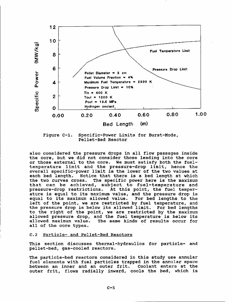
CO
2
<i>
o 0.
o
"o o a CO
12
10
8
6
4
2 -
0.00
Figure C-l,
Pellet Diameter ■ J cm Fuel Volume Fraction «= 4% Maximum Fuel Temperature - 2300 K
Pressure Drop Limit ■ 10%
Tin - 400 K Tout ■ 1200 K Pout - 13.6 MPa Hydrooen coolant ,
0.20 0.40 0.60 0.80 1.00
Bed Length (m)
Specific-Power Limits for Burst-Mode, Pellet-Bed Reactor
also considered the pressure drops in all flow passages inside the core, but we did not consider those leading into the core or those external to the core. We must satisfy both the fuel- temperature limit and the pressure-drop limit, hence the overall specific-power limit is the lower of the two values at each bed length. Notice that there is a bed length at which the two curves cross. The specific power here is the maximum that can be achieved, subject to fuel-temperature and pressure-drop restrictions. At this point, the fuel temper- ature is equal to its maximum value, and the pressure drop is equal to its maximum allowed value. For bed lengths to the left of the point, we are restricted by fuel temperature, and the pressure drop is below its allowed limit. For bed lengths to the right of the point, we are restricted by the maximum allowed pressure drop, and the fuel temperature is below its allowed maximum value. The same kinds of results occur for all of the core types.
C.2 Particle- and Pellet-Bed Reactors
This section discusses thermal-hydraulics for particle- and pellet-bed, gas-cooled reactors.
The particle-bed reactors considered in this study use annular fuel elements with fuel particles trapped in the annular space between an inner and an outer frit. Coolant enters at the outer frit, flows radially inward, cools the bed, which is
C-5

about 2 cm thick, and leaves through the inner frit. Because the particles are small and have a large surface-area-to- volume ratio, heat transfer is excellent.
Several of these annular fuel elements are assembled in a core and may be surrounded by a moderator for a moderated core or assembled without a moderator for a fast core.
Fuel particles comprise a uranium carbide core or kernel encased in layers of porous graphite, pyrolitic graphite, and zirconium carbide cladding. Both moderated and unmoderated cores are considered, and each uses a unique fuel-particle design (see Table C-2).
Table C-2
Assumed Fuel Particle Description
Diameter (mm)
Fuel Kernel Diameter
Low-Density Graphite Diam.
Pyrolitic Graphite Diameter
Zirconium-Carbide Diameter
Moderated
0.234 mm
0.300 mm
0.400 mm
0.500 mm
Unmoderated
0.434 mm
0.634 mm
0.700 mm
0.800 mm
A pellet-bed core is filled with spherical pellets with diam- eters in the range of 1 cm. Coolant enters at one end of the core, passes through the bed, and leaves at the other end of the core; or it may enter through a central duct, flow radially outward through the bed, and exit at the core's outer radius. Inward radial flow is also an option. A pellet was assumed to be composed of many fuel particles (the moderated particle described above) locked in a spherical graphite matrix. The particle loading can be varied to adjust the fuel's specific-power limit and its neutronic behavior.
The heat-transfer and pressure-drop relations for packed spherical beds have been well documented in the literature. Eckert's Heat and Mass Transfer, second edition, published by McGraw-Hill, was used as a reference for this study. To find the specific-power limit for either particles or pellets, we solved the energy-balance equation that equates the thermal power entering the coolant to the thermal power generated by the fuel. This energy-balance equation was solved with two
C-6

restrictions: The first was that the fuel temperature is not allowed to exceed 2300 K at the hottest point in the fuel. Finding the maximum specific power based on this temperature limit involved calculating (1) the convection coefficient of the coolant and (2) the conduction temperature profile in the fuel particle or pellet. For particles, the temperature pro- file was found using a multiple-layer, spherical-conduction analysis. The same type of analysis was used for pellets, but, once the temperature at the pellet's center was found, the profile for a particle was superimposed. Solving the energy-balance equation with the fuel-temperature restriction resulted in what we call the temperature-related specific- power limit.
The second restriction was for pressure drop. The energy- balance equation was solved with the restriction that pressure drop must not exceed a specified percentage of the core's outlet pressure. The result was the pressure-drop-related specific-power limit. For the pellet-bed core, the pressure drop is due only to the pressure drop in the bed itself. For the particle-bed core, pressure drop is found by adding the pressure drop in the bed to pressure drops across frits, through coolant passages entering and leaving the fuel elements, and through coolant passages in the moderator, if there is one. These nonbed pressure drops were calculated using data from BNL's pressure-drop analysis.
The overall specific power limit is the lower of the temperature-related and pressure-drop-related specific-power limits. As explained in the introduction, there is a bed length, that maximizes the overall specific-power limit, and at this length, both fuel temperature and pressure drop are at their maximum allowed values. For shorter beds, specific power is determined by the fuel-temperature limit, and for longer beds it is determined by the pressure-drop limit. For particle beds, the bed length that maximizes the specific power limit is quite short, i.e., generally less than 10 par- ticles long, which is not a practical length; thus, the specific-power limit for particle beds is determined by pressure-drop limitations, not by fuel-temperature limits. In fact, the maximum fuel temperature is somewhat below its maxi- mum allowed value.
Figures C-2 through C-6 show specific-power limits for the various types of particle and pellet cores as a function of bed length. They were calculated using a computer program that incorporated the heat-transfer and pressure drop rela- tions described above.
C.3 Prismatic-Core Reactors
The prismatic-core reactors consist of hexagonally shaped fuel elements grouped together to form a cylindrically shaped core.
C-7

5
O
o
o a
CO 0.00
Figure C-2
Outlet Pressure «= 13.6 MPa Maximum Pressure Drop ■ 10% Inlet Temp. ■ 400 K Outlet Temp. = 1200 K Max. Fuel Temp. - 23 00 K Fuel Volume Fract. ■ 10% Hydrogen coolant
0.10 0.20 0.30
Bed Thickness (m)
0.40 0.50 (E-1)
Specific-Power Limits for Moderated, Burst-Mode, Particle-Bed Reactor
0)
o 0-
Ü 0) a
20
15
10
/ \ Fuel Volume / VFraction = 2%
Outlet Pressure ■ 13.6 MPa Maximum Pressure Drop =10% Inlet Temp. = 400 K Outlet Temp. ■ 1200 K Max. Fuel Temp. ■ 2300 K Pellet Diameter - 2 cm
4% \ Hydrogen coolant
f N \
8%
i i
0.00 0.50 1.00 1.50 2.00 2.50 3.00
Bed Thickness (m)
Figure C-3. Specific-Power Limits for Burst-Mode, Pellet-Bed Reactor
C-8

o Q.
O
O o a w
3 -
2 -
Outlet Pressure = \ Maximum Pressure 1 Inlet Temp. = 900
2.7 MPa Drop = 3% K
Outlet Temp. - 1500 K 1 Max. Fuel Temp - 23 00 K 1 Fuel Volume Fract. ■ 16% I Helium coolant
i i i i i i i
0.00 0.05 0.10 0.15 0.20 0.25 0.30 0.35 0.40 (E-1)
Bed Thickness (m)
o n
O O a CO
Figure C-4. Specific-Power Limits for Unmoderated, MMWSS-Mode, Particle-Bed Reactor
0.00
Outlet Pressure ■= 2.7 MPa Maximum Pressure Drop =3% Inlet Temp. *= 900 K Outlet Temp. «= 1500 K Max. Fuel Temp - 2300 K Fuel Volume Fract. «10% Helium coolant
0.10 0.20 0.30 0.40 0.50 (E-1)
Bed Thickness (m)
Figure C-5, Specific-Power Limits for Moderated, MMWSS-Mode, Particle-Bed Reactor
C-9

09
2
o o a o
ü o a en
0.1
£ .01
- \ Outlet Pressure ■ 2.7 MPa Maximum Pressure Drop "3% Inlet Temp. ■ 900 K
\ '« \ Outlet Temp. - 1500 K : \ ^ \ \ \ \ Max.Fuel Temp. = 23 00 K - v ^ V Pellet diameter « 2 cm
Helium coolant
\ \ ^^.2% Fuel Volume Fract. V
' -.4% ^^^~-^_
^v^ 8% "...
i i 1 1 -_
0.00 0.50 1.00 1.50 2.00 2.50 3.00
Bed Thickness (m) Figure C-6, Specific-Power Limits for MMWSS-Mode,
Pellet-Bed Reactor
The coolant gas (hydrogen for burst-mode operation and helium for MMWSS-mode operation) flows through axial channels within the elements, and the fuel is dispersed within the solid ele- ment material either as a composite or in the form of coated particles. This geometry is used in three reactor concepts: (1) the NERVA derivative, (2) the PLUTO derivative (including the UB2 core and the NERVA/PLUTO hybrid), and (3) the 710 Cermet derivative.
The following is a list of the different variations of these concepts, along with the materials composing the core, and the associated maximum fuel temperature:
Temperatures (K)
Used in Used Illustrations Burst
NERVA (UC2/p,ZrC, C) 2300 2300
NERVA (UC2-ZrC,C) 2700 —
NERVA (UC2-ZrC) 3000 —
PLUTO (U02,BeO) 1900 1900
PLUTO (UC2,C) 2700 2300
PLUTO (UB4,B4C) 2300 2300
710 Cermet (U02/p ,w W) 2800 <2800
Used for Mass Estimates MMWSS*
<1800
<1800
<1800
<1800
<2400
♦Temperature not limiting
C-10

The symbols in parentheses indicate the core materials. The first material listed is the fuel, the second material is the fuel coating, and the last material is the element or matrix material in which the fuel is embedded. If the fuel in the matrix is in the form of a spherical particle, the fuel mate- rial designation is followed by a H/p"; if the core is made of a composite of fuel and matrix material, no coating material is needed, and only two materials are listed.
The specific power for a given concept was determined as a function of the fuel loading and the core length. The fuel loading is defined as the mass of fuel material per unit volume of solid element (i.e., the volume of the element minus the volume of the coolant channels). The fuel loading and core length were treated parametrically because their final values will also depend on reactor criticality and burnup considerations. The maximum specific power was determined such that a prescribed maximum fuel temperature was not exceeded (heat-transfer limit) or a maximum core-pressure drop or sonic velocity limit was not exceeded (hydraulic limit).
A computer program was written to determine the specific power for each of the prismatic-core concepts [Reference 2]. The thermal resistances for the matrix, coating, and fuel mate- rials were all included in the heat-transfer model to deter- mine the temperature drop from the coolant to the fuel centerline. The Taylor equation, given below, was used to calculate the heat transfer coefficient, h, of the coolant. This equation is for turbulent flow in circular channels and is a function of the wall temperature; thus, it must be solved iteratively with Newton's law of cooling to find the wall tem- perature and heat-transfer coefficient.
h = 0.023 Ck/D RE0,8 PR0,4 , (C-l)
C = (yTc)E , (C-2)
E = (1.59D/X - 0.57) , (C-3)
where K = conductivity,
D = channel diameter,
RE = Reynolds number,
PR = Prandtl number,
TH = wall temperature,
Tc = coolant bulk temperature,
x = distance from channel entrance.
C-ll

The pressure drop, AP, across the channel was calculated using
AP = (fL/D) (p/2) V2 , (C-4)
f = 0.184RE-0-2 PR"0"6 , (C-5)
where L = channel length,
p = average coolant density,
V = average coolant velocity.
Figure C-7 shows (for the assumed conditions in Table C-l) the burst-mode specific powers for the three different prismatic- core concepts and their variations (for a 500-kgU/m3 fUel loading). The specific power to the left of the peak is limited by the heat-transfer constraints, whereas the specific power to the right of the peak1 value is limited by the hydraulic constraints. This set of curves cannot really be used for comparing specific powers among the various concepts, because they do not reflect the criticality aspects and other considerations associated with the different fuel loadings, core lengths, and fuel and matrix materials. However, they do provide an indication of what geometric parameter would have to be changed to improve the specific power in either the heat-transfer or hydraulic-limited regions. For example, the NERVA concepts offer very good heat-transfer characteristics but poor hydraulic characteristics with respect to specific power. To improve the hydraulic characteristics (at the expense of the heat-transfer characteristics) , it would be necessary to use fewer channels of larger diameter. This would shift the specific power peak to the right. The PLUTO concept that uses UB2 and B4C would require the exact opposite change. That is, it would be necessary to use more channels of smaller diameter to increase the specific power in the heat-transfer-limited region.
All of the concepts analyzed consist of the same basic geom- etry, i.e., a group of hexagonal elements with a certain number of channels formed within each element for coolant flow. It would, therefore, be possible to "redesign" (without consideration for structural integrity) all of the concepts in order to optimize the specific power with respect to channel diameter and number. Thus, with respect to thermal hydraulic performance, the only parameters that distinguish one concept from another are the thermal conductivity and the maximum operating temperature. However, it may not be possible to take advantage of a material's higher conductivity or tempera- ture capability due to the imposed hydraulic limits. Whether a higher conductivity or temperature will be of benefit can only be determined after considering the criticality and fuel damage aspects of the concept.
C-12

'—
2 «i * o a.
u «i a (A
55
50
45
40
35
30
25
20
15
10
'—i—i—r Burst
I I I I I I I
— © D NERVA (UC/P, ZrC, C) —
,' * & NERVA (UC-ZrC, C)
© O NERVA (UC, ZrC) \
V» 2 PLUTO (UOjj, BeO)
+ PLUTO (UC, C) —
\ ■ PLUTO (UB4, B4C)
▲ CERMET (UOj/P, W, W) —
—
*-*-*' -S'*
Fuel Loading = I I I
500 kg/m3
I I ! I I I I I
0.4 0.6 0.8 1.0 1.2
Core Length (m)
1.4 1.6
Figure C-7. Burst-Mode Specific Power for Prismatic-Core Concepts
For the MMWSS mode, specific power is limited by the imposed pressure drop and is not a function of the heat-transfer para- meters (i.e., the thermal conductivity and the maximum fuel temperature). Thus, the power density is only a function of the core geometric data. The geometric data for the three concepts are summarized in Table C-3.
The results for the MMWSS-mode specific-power calculations are shown in Figure C.8 for all three prismatic-core concepts. The core pressure drop limit was assumed to be 1 percent in these illustrations; the other assumed operating conditions are as in Table C-l. The figure shows the specific power as a function of fuel loading for a core length of 1.0 m. The following formula can be used to determine the specific power for other core lengths for the MMWSS mode:
PS(L) = Ps(1.0) / L 3/2 (C-6)
where Ps = specific power and L = core length (m).
C-13
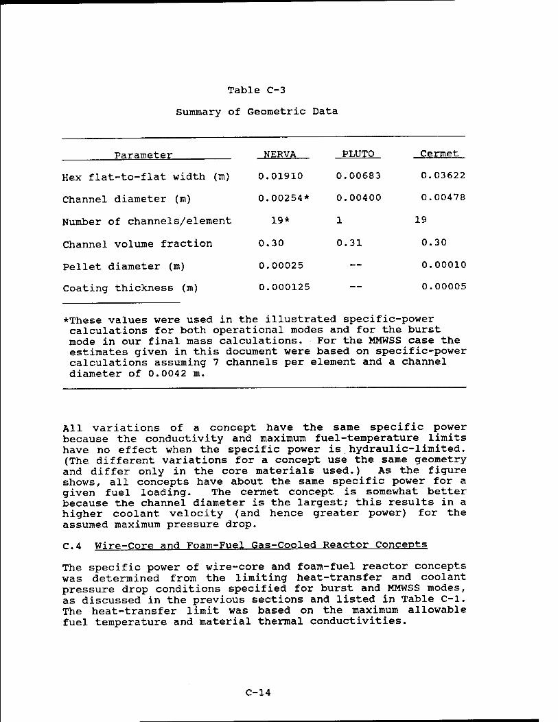
Table C-3
Summary of Geometric Data
Parameter NERVA PLUTO Cermet
Hex flat-to-flat width (m) 0.01910 0.00683 0.03622
Channel diameter (m) 0.00254* 0.00400 0.00478
Number of channels/element 19* 1 19
Channel volume fraction 0.30 0.31 0.30
Pellet diameter (m) 0.00025 — 0.00010
Coating thickness (m) 0.000125 — 0.00005
*These values were used in the illustrated specific-power calculations for both operational modes and for the burst mode in our final mass calculations. For the MMWSS case the estimates given in this document were based on specific-power calculations assuming 7 channels per element and a channel diameter of 0.0042 m.
All variations of a concept have the same specific power because the conductivity and maximum fuel-temperature limits have no effect when the specific power is hydraulic-limited. (The different variations for a concept use the same geometry and differ only in the core materials used.) As the figure shows, all concepts have about the same specific power for a given fuel loading. The cermet concept is somewhat better because the channel diameter is the largest; this results in a higher coolant velocity (and hence greater power) for the assumed maximum pressure drop.
C.4 Wire-Core and Foam-Fuel Gas-Cooled Reactor Concepts
The specific power of wire-core and foam-fuel reactor concepts was determined from the limiting heat-transfer and coolant pressure drop conditions specified for burst and MMWSS modes, as discussed in the previous sections and listed in Table C-l. The heat-transfer limit was based on the maximum allowable fuel temperature and material thermal conductivities.
C-14

S
O a. o
"5 a m
1.6
1.5
1.4
1.3
1.2
1.1
1.0
0.9
0.8
0.7
0.6
0.5
0.4
0.3
0.2
0.0
T MMWSS
Concept
D NERVA
A PLUTO
O CERMET
0-1 - Core Length = 1.0
1 0.0 0.2 0.4 0.6
Fuel Loading (kg/m3) x 10+3
0.8 1.0
Figure C-8. MMWSS-Mode Specific Power for Prismatic-Core Concepts
In the wire-core reactor, the coolant flows axially into the open center, then radially out through the core. No pressure drop was calculated for the axial flow path. The specific power of the wire-core reactor concept for the burst mode is presented in Figure C-9. The decrease in specific power with increasing core thickness (i.e., the radial flow direction) is due to the reduction in coolant flow necessary to maintain the specified pressure drop. The maximum allowable temperature for UN fuel for the burst mode depends on the pressure of the nitrogen gas from thermal dissociation and the resulting ef- fect on the cladding. Because this maximum temperature will depend on cladding thickness and other design variables, no absolute maximum temperature (below the melting temperature) can be assigned. Thus, a practical limit of 2000 K was used to obtain Figure C-9. The tungsten-clad fuel wire was assumed to be a constant 1-mm-diameter wire spaced axially on 1.7-mm centers and radially on 1.4-mm centers. This spacing deter- mined the void fraction of the woven wire core. The calcula- tions were also based on a radially and axially flat power profile. The parametric investigations varied radial core thickness and fuel-to-wire-diameter ratios. The core heat- transfer and pressure-drop correlations were obtained from Reference 3 for staggered cross-rod matrices.
C-15

0.8 FUEL TO WIFE DIA.
0.667 FUEL TO WRE DIA.
0.571 FUEL TO WIFE DIA.
0.5 FUEL TO WIRE DIA.
100
0)
5
of ai
O ÜL
O Ü.
Ü LU 0. W
10
\ \
13.6 MPa; 10% Press. Drop H2 GAS 400 K Inlet. 1200 K Outlet
UN FUEL 1 rvfvl DIA. FUEL WIRE 0.663 VOID FRACTION
\
i i ' i ' i I i i i—i L I I I i i i i 1—i 1—i L.
0.00 0.10 0.20 0.30 0.40
CORE THICKNESS, M
0.50 0.60
Figure C-9. Specific Power of Wire-Core Reactor in Burst Mode
The specific power of the wire-core reactor in the MMWSS mode is presented in Figure C-10. The maximum fuel temperature was assumed to be 1800 K; however, fuel temperature was not limiting. The specific power again decreases with increasing radial core thickness with similar limitations due to pressure drop. No axial flow pressure drop was accounted for. The axial coolant velocity in the wire-core reactor depends on the diameter of the axial flow path, the core dimensions, and whether coolant flows into the core center from one or both ends. Thus, for Figure C-9 in the burst mode (0.25-m-diameter axial flow path, equal core length and outer core diameter, and coolant flow from both ends), the axial coolant velocity is less than Mach 0.3 for core thicknesses less than 0.45 m. For the core thickness range shown in Figure C-10 for the MMWSS mode, the axial coolant velocity for these conditions was always less than Mach 0.3.
Very little design information was available for the foam-fuel reactor, and more design and performance information would be needed to really begin to understand the specific-power limits for this fuel. However, for purposes of this study, the particle-bed reactor was assumed to be fueled with foam fuel. That is, the annular frit portion of the particle-bed reactor was assumed to contain UC2 foamed fuel. Also, fuel porosity, or the fuel void fraction, was varied from 20 percent to 95 percent. The foam fuel was assumed to be randomly oriented
C-16

10000
0.6 FUEL TO 0.667 FUEL 0.571 FUEL 0.5 FIEL TO WIRE DIA. TO WIRE DIA TO WIRE DIA. WIRE DIA
UN FUEL Tmax - 1800 K He 2.7 MPa
:*% 900 K TO 1500 K a> |/\\\\ 3% PRESS DROP
im. 0.663 VOID FRACTION ¥ ^ 1000 5 i \vs •■■.. * : v><\
_ >v " \ *""•■■
oc ^\ v * ^ -s! ""■•-.. UJ
o 100 X:^^^c^-___
a : ^^^^^^^^r.--^-:.:—— ü " ""~-—_^~~ n._ ~ ——___ C ■—~-~-^-iiiiii~~~ ~~~- — ü ■ _
UJ DL
10 r " ■ ■ «
1 i i i i i i i i 1 1 1
0.00 0.10 0.20 0.30 0.40 0.50 0.60 0.70 0.80 0.90 1.00 1.10 1.20
CORE THICKNESS, M
Figure C-10. Specific Power of Wire-Core Reactor in MMWSS Mode
0.55-mm diameter wires, including a 0.1-mm-thick coating. Heat-transfer and pressure-drop correlations were also obtained from Reference 3 for randomly stacked woven-screen materials. Typical burst and MMWSS mode results are shown in Figures C-ll and C-12 for UC2 fuel. The configurations shown are only representative of the study and do not necessarily provide an optimum design or configuration for either burst or MMWSS modes.
Specific power for a foam-fuel reactor increases as porosity increases, because more coolant can flow through the core for a given pressure drop. The specific-power limit is reached, however, when the maximum fuel temperature is reached and will occur at a different porosity for each different core configu- ration. In Figure C-ll, the maximum specific power is reached at about 40 percent porosity. However, minimum core mass may be determined by factors other than thermal/hydraulic con- siderations and may occur at a porosity other than this.
C-17

5
of 111
o a o LL
Ü UJ a w
a
2
of UJ
O a o LL
Ü LU a CO
0.00 0.10 0.20 0.30 0.40 0.50 0.60 0.70 0.80 0.90 1.00
POROSITY
Figure Oil. Specific Power of Foam-Fuel Reactor Burst Mode
2.7 MPa 4 3% PRESS DROP UC2 FUEL AT 1800 K MAX. He GAS 900 K IN & 1500 K OUT 2 CM BED THICKNESS
0.00 0.10 0.20 0.30 0.40 0.50 0.60 0.70 0.80 0.90 1.00
POROSITY Figure C-12. Specific Power of Foam-Core Reactor
in MMWSS Mode
C-18

For MMWSS mode (Figure C-12), the maximum specific power occurs at about 60 percent porosity (also for the UC2 fuel in a cylindrical fuel-element configuration 3 cm I.D. x 5.5 cm O.D. x 25 cm length). Coolant flows through this element radially inward and axially out of the center. Only pressure drops through the foam fuel were considered in the calcula- tions used to obtain Figures C-ll and C-12. A moderated foam- fuel element (similar in coolant flow path configuration to the moderated particle bed reactor) would have approximately half the specific power of Figure C-12 for the MMWSS mode. These additional pressure drops, including the pressure drop through the moderator, were not considered in the mass calcu- lations since the uncertainties in the other foam fuel para- meters overwhelm the uncertainty in the core pressure drop.
C.5 References
1. M. W. Edenburn, The Effect of Operating Temperature on Open MMW Space Power Systems. Fourth Symposium on Space Nuclear Power Systems, Albuquergue, New Mexico, Jan- uary 12-16, 1987.
2. D. Dobranich, A Computer Program to Determine Specific Power for Prismatic Cores. SAND87-0735, May 1987.
3. Kays, W. M. and A. L. London, Compact Heat Exchangers. McGraw-Hill Book Co., 3rd ed., 1984.
C-19

APPENDIX D
MASS STUDIES
M. S. Y. Chu V. J. Dandini A. C. Marshall
D-l

D.l Method
The principal tool used for the reactor and shield mass studies was the RSMASS code (Ref. 1) . RSMASS is a simple mathematical model that was developed to provide rapid esti- mates of reactor and shield masses for space-based reactor power systems. RSMASS uses approximations rather than corre- lations or detailed calculations to estimate the reactor fuel mass and the masses of the moderator, structure, reflector, pressure vessel, miscellaneous components, and the reactor shield. The fuel mass is determined either by neutronics limits, thermal/hydraulic limits, or fuel damage limits—whic- hever yields the largest mass.
RSMASS requires the user to specify the reactor power and energy, 24 reactor parameters, and 20 shield parameters. This parametric approach should provide good mass estimates for a very broad range of reactor types. Reactor and shield masses calculated by RSMASS were found to be in good agreement with the masses obtained from detailed calculations.
Mass estimates were begun using the proposers' input data. Important input data includes the molecular ratio of the moderator to the fuel, the type of moderator (if used), the volume fraction of the fuel and the moderator, the fuel burnup limit, the limiting specific power (thermal power per unit mass of fuel [see Appendix C]), the ratio of the structural volume to the fuel and moderator volume, etc. Using this and other input data, RSMASS provides estimates of the reactor and shield mass. Parametric studies were then performed varying fuel loading, coolant channel diameter, fuel size, fuel type, core geometry, etc., to obtain the minimal reactor and shield mass. These estimates, however, should not be considered to represent the masses for optimized systems. The mass studies are approximate and were used to determine whether a reactor concept would be exceptionally heavy or exceptionally light. Further mass reductions could be achieved by detailed optimi- zation for many of these concepts; however, this should be done in an overall systems context.
The masses obtained from this study were for the assumed oper- ating conditions described in Appendix C; different operating conditions can have a substantial impact on all of the calcu- lated masses. A comparison of the relative masses of the various concepts, however, is not expected to be very sensi- tive to the chosen operating conditions.
D-2

D.2 Burst-Mode Mass Estimates
D.2.1 Pellet-Bed Reactor
The pellet-bed reactor was assumed to use a fuel bed in the form of graphite spheres imbedded with 500-/i-diameter UC2 particles contained in a cylindrical pressure vessel. Reactor masses were calculated for several pellet diameters, and, for each pellet diameter, the effect of various fuel loadings was studied. When an axial flow path was used, very large reactor masses were obtained. It was found that the reactor mass could be reduced by almost a factor of 3 by assuming radial flow from the center of the core to the core periphery. This assumption reduced the length of the flow path and conse- quently the pressure drop through the fuel bed at the same flow velocity. Because a 10 percent pressure drop is allowed, greater flow velocities and consequently improved heat trans- fer could be attained without exceeding the pressure-drop limit. The improved heat transfer increased the allowed specific power and reduced the fuel and reactor mass; conse- quently, radial flow was assumed for the pellet-bed studies.
Pellet sizes were varied between 0.5 and 4 cm, and fuel loading was varied between 100 and 900 kgU/m3. The lowest mass of 5.4 metric tons was obtained for 1.5-cm pellets with a loading at the assumed maximum value of 900 kgU/m3. At lower loadings, the reactor is criticality-limited, and a moderator mass penalty occurs.
D.2.2 PLUTO Derivative Reactor
As described in Appendix A, the PLUTO derivative concept con- sists of unclad U02-BeO hexagonal fuel elements 6.83 mm across the flats with a single 4-mm coolant hole. Fuel loadings were explored from very low loadings up to a maximum loading of 900 kgU/m3. The minimal reactor mass of 3.7 metric tons was found to occur at a fuel loading of only 19 kgU/m3, because both the critical mass and the fuel mass based on the specific-power limits decrease with decreasing fuel loadings to very low loadings. For loadings much less than 19 kgU/m3
the critical mass increases.
D.2.3 NERVA/PLUTO Hybrid Reactor
This concept uses the PLUTO geometry with NERVA fuel (UC2) . The fuel loading was varied between 300 and 900 kgU/m3. A minimum reactor mass of about 3.2 metric tons was observed for the assumed maximum fuel loading of 900 kgU/m3. Although the fuel mass increases slightly with increasing loading, the decrease in moderator mass, for this concept, results in a minimal mass at the highest loading.
D-3

D.2.4 UB2 Reactor
This concept uses the PLUTO geometry with UB2 fuel in a B^C matrix. The fuel loading was varied from 300 to 700 kgU/m3. The minimal reactor mass of about 3.9 metric tons occurred at about 500 kgU/m3. Above this loading, the specific power decreases and the fuel mass increases. Much below the 500- kgU/m3 loading, the moderator mass becomes substantial. Al- though the proposer has suggested enriching the fuel in B11 to prevent parasitic neutron capture in B10, our neutronics cal- culations show that this should not be necessary because the spectrum will be relatively hard and B10 parasitic capture should not be significant if a 500-kgU/m3 loading is used.
D.2.5 Cermet Reactor
The cermet reactor uses hexagonal fuel elements and no modera- tor. Each fuel element is 3.7 cm across the flats and is surrounded by a thin cladding (0.025 cm thick). The standard fuel element uses U02/W and has 19 coolant channels 0.34 cm in diameter. Fuel loadings were varied from 2000 kgU/m3 up to an assumed maximum loading of 6000 kgU/m3. Coolant channel diam- eters from 0.34 up to 0.5 cm were investigated.
Although higher loadings imply lower specific powers, they also result in less structural mass; consequently the highest permitted fuel loading resulted in the lowest reactor mass. It was also found that if the coolant hole diameter is increased to 0.5 cm diameter (30 percent void), the reactor mass can be reduced substantially to about 3.0 metric tons. The greater hole size reduces the pressure drop and increases the allowed specific power. The net effect is a reduction in fuel and reactor mass.
D.2.6 NERVA Derivative Reactor
The NERVA derivative concept uses hexagonal fuel elements 1.91 cm across the flats with 19 coolant holes 0.23 cm in diameter. These hexagonal fuel elements surround a central support element. The support element contains a cooled tie tube and, for the moderated concept, an annulus of ZrH1-7 moderator. Coated UC2 fuel particles were assumed. Fuel loadings from 300 to an assumed maximum of 900 kgU/m3 were investigated. A minimum reactor mass of 3.3 metric tons was obtained at the highest fuel loading for the unmoderated NERVA. The highest fuel loading resulted in the highest fuel mass (because both the critical mass and the fuel mass deter- mined by thermal hydraulics increase with increasing fuel-to- moderator ratios over this range), but the reduction in moder- ator mass more than compensated for this fuel-mass increase. The moderated burst mode reactor mass was about 2.4 metric tons at a fuel loading of about 400 kg/m3.
D-4

D.2.7 Particle-Bed Reactor
The particle-bed reactor incorporates a number of fuel ele- ments consisting of two concentric porous cylinders (called frits). The space between the frits contains a 2-cm-thick bed of coated 500-/*m-diameter UC2 particles. The inlet cooling gas flows axially between the fuel elements (and ZrH1-7 moder- ator, if present), radially through the bed and frits, then exits through the center hole of the inner frit.
Greater attention has been paid to this concept than to some of the other concepts at both BNL and SNLA (for example, moderator fraction optimization studies were carried out at SNLA, as described in Reference 2); consequently, the proposers' parameters should be reasonable. Because the particle-bed concept is the most difficult to analyze, and because much work has already been done for this concept, no further optimization studies were carried out. Instead, the principal effort for this concept was devoted to obtaining better input data, such as specific-power input, structure-to- fuel-and-moderator volume ratios, and critical mass input. When all of this improved input data was used in RSMASS, the mass of the particle-bed concept was estimated to be 4.07 metric tons. BNL has suggested that very-high purity LiH7
could be used instead of ZrH1-7 to reduce the reactor mass.
D.2.8 Wire-Core Reactor
The wire-core reactor uses UN fuel enclosed within a thin hollow wire made of tungsten. The fuel wires are woven between solid tungsten spacer wires to form an open three- dimensional mesh. These spacer wires are spaced 13 mm apart in the axial direction. In the proposed reactor, the gas enters the core at the centerline, and the flow then turns radially outward into the wire fuel core.
The following fuel-to-wire-diameter ratios were used in the parametric calculation: 0.5, 0.57, 0.667, 0.75, and 0.8. These ratios correspond to the following fuel loadings: 2875, 2778, 5239, 6470, and 7360 kgU/m3. A minimal reactor mass of 2.2 metric tons was obtained at the assumed maximum fuel loading of 7360 kgU/m3 (minimal clad thickness). The minimal mass occurs at the highest fuel loading because a substantial mass penalty is paid for the structural mass of the tungsten cladding.
D.2.9 Foam-Fuel Reactor
The foam-fuel reactor is not well defined. The fuel consists of UC2 fuel in the form of a porous foam coated with graphite and ZrC. It is assumed that the foam fuel occupies the loca- tion of the particle bed in the particle-bed concept and that the foam-fuel approach may be considered as an alternative to
D-5

the particle-bed reactor. The coolant gas passes through the pores in the fuel.
As described in Appendix C, the fuel was assumed to be ran- domly oriented 0.55-mm-diameter UC2 "wires," including a 0.1- mm-thick coating. The proposers1 estimate of the fuel porosity was over 90 percent. In our calculation we used a more optimistic porosity of 80 percent. Our uncertainty anal- ysis looked at porosities as low as 70 percent and as high as 90 percent. The estimated reactor mass was 2.5 metric tons. It must be pointed out, however, that nothing is known about this fuel, and these calculations are based on guesses about the fuel characteristics; consequently, the mass uncertainty for this concept is substantial.
D.3 MMWSS-Mode Mass Estimates
D.3.1 Pellet-Bed Reactor
As for the burst mode, the coolant for the MMWSS mode was assumed to flow from the center of the core to the periphery. This flow geometry reduces the reactor-plus-shield mass by almost a factor of 3 relative to the proposed end-to-end flow. Loadings between 100 and 900 kgU/m3 and pellet diameters between 1 and 8 cm were investigated. The reactor-plus-shield mass reached a minimum of 9.8 metric tons (4.9 metric tons for the reactor) at a loading of about 900 kg/m3 and a pellet diameter of 2 cm.
D.3.2 PLUTO Derivative
Fuel loadings between 100 and 900 kgU/m3 were investigated. A minimal reactor-plus-shield mass of 4.9 metric tons was obtained for an assumed maximum loading of 900 kgU/m3. The reactor mass for this case was 2.5 metric tons. The optimi- zation for this case is linked to the moderator mass, which increases as loading decreases.
D.3.3 NERVA/PLUTO Hybrid Reactor
The fuel loading was varied between 300 and 900 kgU/m3 for the NERVA/PLUTO Hybrid. At an assumed maximum loading of 500 kgU/m3, a minimal reactor-plus-shield mass of 9.3 metric tons was obtained. The reactor mass at this loading was 5.8 metric tons.
D.3.4 UB2 Reactor
Fuel loadings between 300 and 900 kgU/m3 were studied for the UB2 reactor. The minimal reactor-plus-shield mass of 9.0 metric tons (5.5 metric tons of which is associated with the reactor) was obtained at an assumed maximum loading of
D-6

900 kgU/m3. Below this loading, the moderator mass penalty increases the reactor mass.
D.3.5 Cermet Reactor
The channel sizes used in this analysis were 0.34 cm and 0.5 cm. Two fuel loadings, 4000 and 6000 kgU/m3, were studied. A minimum reactor mass was obtained for the 6000 kgU/m3 loading and 0.5 cm diameter coolant channel. The reactor mass for this case was 6.7 metric tons and the mass of the reactor-plus-shield was 8.0 metric tons.
D.3.6 NERVA Derivative Reactor
For the NERVA derivative reactor, loadings between 300 and 900 kgU/m3 were studied. A minimal reactor-plus-shield mass of 9.5 metric tons occurred at a loading of about 500 kgU/m3
for the unmoderated reactor. The reactor mass for this case was 6.0 metric tons. For the moderated NERVA the minimum reactor-plus-shield mass of 6.75 metric tons occurred at a loading of about 400 kgU/m3. The reactor mass for the moder- ated NERVA was 3.9 metric tons.
D.3.7 Particle-Bed Reactor
Due to the complexity of the analysis for this concept, only a few options were explored to reduce reactor mass. Since this concept has been investigated for some time by the proposers, it is expected that the chosen parameters are reasonable. A reactor mass of 5.6 metric tons and a reactor-plus-shield mass of 9.5 metric tons were obtained for the unmoderated particle- bed reactor. A ZrH1-7 moderated case was also investigated, but for the chosen parameters, the reactor mass was greater than for the unmoderated case. However, since a variety of moderator-to-fuel ratios, bed thicknesses and types of modera- tors could be used, it is reasonable to believe that a thorough optimization study could yield a design with an ap- preciably lighter reactor and shield mass.
D.3.8 Wire-Core Reactor
Fuel-to-wire ratios between 0.5 and 0.8 were studied to mini- mize the reactor mass. At a ratio of 0.8, the minimum reactor-plus-shield mass was 3.6 metric tons and the reactor mass was 2.6 metric tons. This surprisingly low mass is a result of highly compact core with a large heat transfer sur- face area and no moderator mass. (The mass in our preliminary report used an approximate core thickness to obtain specific powers which resulted in a substantial over- prediction of the wire core mass.) Despite the low mass prediction for assumed nominal parameters, the uncertainty in the fuel performance for the wire core results in a large upper bound for the un- certainty limits.
D-7
D.3.9 Foam-Fuel Reactor
The uncertainties in the foam fuel parameters are very large. For a nominal choice of fuel parameters the reactor-plus- shield mass was 12.8 metric tons and the reactor mass was estimated to be 8.4 metric tons. It must be emphasized, how- ever, that the uncertainty in the foam fuel reactor mass is enormous.
D.4 References
1. A. C. Marshall, RSMASS: A Preliminary Reactor/Shield Mass Model for SDI Applications, Sandia National Laboratories, Albuquerque, NM, SAND86-1020, 1986.
2. D. R. Gallup, SNLA, internal memorandum to L. 0. Cropp, SNLA, "Criticality Calculations for the BNL Concepts," September 11, 1986.
D-8

APPENDIX E
ATTRIBUTE REVIEW
A. C. Marshall
E-i

Attribute Review
This review of the nine candidate gas-cooled reactor concepts was guided by a list of attributes for space-based power sys- tems (Reference 1). The attribute list and their definitions are given in Section E.3 of this appendix. The reviewers included nuclear engineers, mechanical engineers, and physi- cists with broad backgrounds. Materials specialists and other staff were consulted when necessary. Nuclear engineers from this group were asked to represent proponents and opponents for each concept. This approach, it is hoped, identifies the strengths and weaknesses of each concept. After many meetings, studies, and long discussions, a score of "good," "fair," or "poor" was awarded to each concept for each attri- bute. The guidelines for scoring and the results of this review are presented below:
E.1 Burst Mode
E.l.l Technical Risk
For this attribute the scoring was guided by the following definitions:
Good - A substantially similar reactor concept has been built and successfully tested.
Fair - The experience base is limited, but there are no insur- mountable issues.
Poor - There is, at most, a very limited technical base and significant issues have been identified, or past at- tempts to use the concept have not been successful.
Particle-Bed - Fair The particle fuel has been developed for the HTGR and AVR reactors (Reference 2), but a reactor has never been built and tested in this configuration, and these types of fuel particles have not been tested for burst- mode conditions. No overwhelming problems are identi- fied.
NERVA Derivative - Good Twenty reactors were built and tested, leading to the NERVA derivative reactor. Successful operation has been demonstrated for operating conditions similar to, but more severe than, the expected SDI operating condi- tions. A review of the test data has determined that the NERVA technology is essentially proven technology (Appendix G) for the burst-mode operating conditions. If very rapid power-ramps (seconds) are needed, the fuel is predicted to perform adequately; however,
E-2

demonstration of the rapid start capability will be required.
Pellet-Bed Reactor - Fair (+) The successful AVR terrestrial reactor (Reference 2) is very similar to the proposed pellet-bed reactor. This concept was never tested in a flowing hydrogen environ- ment or at the proposed power densities. Coating technology to protect the large pellets from hydrogen corrosion would also need to be developed. There are also differences in core geometry, and the AVR used an axially unconstrained fuel bed rather than the proposed fixed bed, which is constrained on all sides and may be subject to differential expansion considerations.
PLUTO Derivative - Good (-) The substantially similar PLUTO reactor was success- fully tested. This concept was never tested in a flowing hydrogen environment or at the anticipated temperatures and temperature gradients. The design inlet temperature for PLUTO was 860 K, and the peak fuel temperature was 1650 K (Reference 3). Inlet tem- peratures of 300 K and peak fuel temperatures of 1900 K have been assumed in this analysis. We have performed a preliminary stress analysis for the fuel that sug- gests that thermal stress cracking of the fuel may occur at the expected temperature gradients. It is not clear, however, that limited cracking will pose a pro- blem for burst-mode operation.
UB2 Reactor - Fair (-) Although this fuel was never developed, no overwhelming problems have been identified.
NERVA/PLUTO Hybrid - Good (-) The NERVA derivative reactor is substantially similar to this concept, although this configuration has never been tested.
Wire-Core - Fair Wire-core fuel has been built and some testing of simi- lar "ribbon fuel" has been conducted. No overwhelming problems have been identified.
Foam-Fuel - Poor This represents a totally new reactor fuel concept. Issues concerning potential clumping of the fuel, fuel structural ruggedness, fabrication procedures, and maximum temperatures have been raised.
E-3

Cermet Reactor - Fair Tests conducted for the expected burst-mode conditions (limited thermal cycling and 1200 K outlet temper- atures) show good fuel performance (Reference 4); how- ever, a substantially similar reactor has not been built and tested for burst-mode conditions.
E.1.2 Mass
All gas-cooled concepts - Good
Although some mass differences were observed for the various concepts, the mass for all of the concepts is small. Also, there does not appear to be any substantial launch cost savings that could be obtained that would merit the increased development cost to reduce reactor weight. Although this attribute is considered a nondiscriminator, based on this study, the mass attribute was retained to emphasize this conclusion.
E.1.3 Safety
Insufficient Information to Discriminate.
There was a great deal of discussion and disagreement on the safety attribute before it was unanimously concluded that there was insufficient information to score any concept dif- ferently from any other concept. This does not imply that safety is not a discriminator; on the contrary, it is an important discriminator. Although we have carried out a pre- liminary safety study which supports our conclusions, until design work is sufficiently resolved and a great deal of safety analysis has been completed, no scoring can be provided.
E.1.4 Survivability
This attribute was considered to be a system-level attribute wherein the potential vulnerability of components, such as the radiator, may serve to discriminate between concepts. Gas- cooled reactors surrounded by a thick pressure vessel do not appear to be sensitive to the concept choice in regard to the issue of survivability. Furthermore, the hostile environment has not yet been adequately defined.
E.1.5 Reliability
This attribute is effectively included in technical risk and development cost, since all reactors will need to meet the same minimum requirement for reliability.
E-4

E.1.6 Power
The mass calculations are based on the assumption of a 500-MW (electrical) power level: consequently, the only discrimina- tion based on power is the amount of excess power a concept possesses for the same reactor mass. In other words, if a concept is limited by neutronics at 500 MW electrical, an increase in the power requirement (relative to the assumed 500 MW electrical) may not increase the reactor mass. A pre- liminary study has shown that the mass of all of these concepts will be sensitive to significantly higher power requirements.
E.1.7 Operation Time
All of the proposed reactor concepts can operate well in excess of the assumed operation times without a substantial increase in mass.
E.1.8 Development Cost
The scoring for this attribute was based on the following:
Good - An essentially equivalent fuel form and reactor system has been developed.
Fair - The fuel form has been developed but reactor modifi- cation or development is required.
Poor - Only limited or unpromising development work has been completed on the fuel form.
Particle-Bed - Fair Only the fuel form has been developed; the rest of the reactor needs to be developed. Also, the type of fuel particle proposed has not been developed and tested for burst-mode conditions.
NERVA Derivative - Good The equivalent fuel and reactor have been developed. In fact, an on-site review has determined that all drawings, fabrication procedures, materials certifica- tions, etc., for most recent NERVA designs appear to be totally retrievable (see Appendix H).
Pellet-Bed - Fair A similar fuel form has been developed and operated (AVR reactor) with a helium coolant, but the reactor and fuel were not developed for the more severe burst- mode operating conditions.
E-5

PLUTO Derivative Reactor - Fair (+) The fuel form and reactor have been developed and tested for test conditions similar to burst-mode re- quirements, but air was used instead of hydrogen, and the temperatures and temperature gradients were less severe than the anticipated conditions. Also, the original PLUTO reactor contained internal structure; the PLUTO derivative reactor has been proposed to possess no internal structure.
UB2 - Poor Fuel form totally undeveloped.
. NERVA/PLUTO Hybrid - Fair The fuel form can be the same as for NERVA, but the reactor system in this configuration has never been developed.
Wire-Core - Fair The fuel form has been fabricated using U02/Nichrome, but the fuel and the rest of the reactor will need to be developed for burst-mode conditions.
Foam-Fuel - Poor No experience at all, and many issues will need to be resolved. Full development effort required.
Cermet - Fair Tests conducted for burst-mode conditions show good fuel performance, but a reactor has not been built and demonstrated for burst-mode conditions.
E.1.9 Fabrication Cost
The scoring for this attribute was based on the following:
Good - Requires only simple processes and relatively inexpen- sive materials.
Fair - Intermediate between good and poor.
Poor - Requires complex tooling or expensive processes.
Particle-Bed - Fair Some fabrication complexity, but no very expensive processes identified.
NERVA Derivative - Fair (As for particle bed.)
Pellet-Bed - Good Simple geometry and straightforward fabrication pro- cedures .
E-6
PLUTO Derivative - Fair (As for particle bed, except that some complexity is expected in working with BeO.)
UBg Reactor - Fair (As for particle bed, provided that spectrum is relatively fast and, consequently, very pure B11 is not required.)
• NERVA/PLUTO Hybrid - Fair (As for particle bed.)
Wire-Core - Good Straightforward fabrication procedures, similar to thermocouple fabrication procedures.
Foam-Fuel - Good Simple fabrication procedures, provided that develop- ment is successful.
Cermet - Fair (-) Fabrication for tungsten-based cermet should be expen- sive, but reactor design is relatively simple.
E.1.10 Manufacturability
Included in fabrication costs.
E.l.ll Controllability
This is effectively covered by technical risk and development costs, because all reactors will need to meet some established controllability criteria. No overwhelming problems in attaining adequate controllability for any of these concepts are foreseen.
E.1.12 Testability
No discrimination identified at the reactor level.
E.1.13 Volume/Area
Not a discriminator among gas-cooled reactors.
E.1.14 R&D Payoff
Not a discriminator.
E.1.15 Effluent
Not a discriminator among gas-cooled reactors.
E-7

E.1.16 Load Following
Related to controllability at reactor level.
E.1.17 Deployability
Not a discriminator among gas-cooled reactors.
E.1.18 Operational Life
Not a discriminator.
E.1.19 Safeguards
Not a discriminator. All >20 percent enriched and >5 kg of
U235.
E.1.20 Initial Operational Capability
Effectively included in operational cost.
E.1.21 Mechanical Compatibility
Not a discriminator.
E.1.22 Modal Shift Time
Insufficient data to discriminate.
E.1.23 Thermal Compatibility
Not a discriminator.
E.1.24 Strategic Materials
Based on the expected temperature requirements, all strategic materials can be engineered around.
E.1.25 Special Interfaces
Not a discriminator. No requirements identified.
E.1.26 Maintenance and Repair
Not a discriminator for burst-mode operation.
E.1.27 Radiation Compatibility
Not a discriminator.
E.1.28 Environmental Compatibility
Not a discriminator.
E-8

E.1.29 Electromagnetic Compatibility
Not a discriminator.
E.1.30 Design Change Tolerance
Covered by excess power attribute.
E.1.31 Shared Functions
Although an important attribute for gas-cooled reactors (which can use weapon hydrogen), it is not a discriminator among gas- cooled reactor concepts.
E.1.32 Upgradability
Not a discriminator.
E.1.33 Quality Assurance
Covered by fabrication cost.
E.1.34 Auxiliary Energy Requirements
Not a discriminator.
E.1.35 Operation and End-of-Life Costs
Not a discriminator.
E.1.36 Life Extendability
Not a discriminator
E.1.37 Intangibles
Not a discriminator
E.2 MMWSS Mode
The guidelines used for scoring the MMWSS mode were the same as for the burst mode, except that the "strategic materials" attribute was not considered to be a discriminator for the burst mode, whereas it is a discriminator for the MMWSS mode. Consequently, the guidelines will be given only for the stra- tegic materials attribute in this section. Also, the reasons other attributes were not chosen as discriminators will not be repeated here because they are the same for both modes. One exception is "operating time": operating time is not a discriminator for the MMWSS mode because all concepts will be equally sensitive to increases in the required operating time. The results of the MMWSS attribute are presented below:
E-9

E.2.1 Technical Risk
Particle-Bed - Fair Some of the technology has been established for the fuel in the high-temperature gas reactor (HTGR) and AVR reactor programs, but a substantially similar reactor has not been developed and tested. Since this unique approach of micro-particles with micro-flow passages has never been tested, issues relating to this new geometry must be considered (e.g., frit plugging during long-term operation, as discussed in Appendix F).
NERVA Derivative - Good The NERVA configuration has been tested, and the con- cept is substantially similar to the HTGR with high burnup capability.
Pellet-Bed Reactor - Fair (+) No breakthrough needed. Although similar to the AVR reactor, there are differences which prohibit a score of "good." These differences include the use of a fully constrained bed for the pellet-bed reactor and the use of a continually recirculating fuel bed in the AVR.
PLUTO Derivative - Fair Some short-term testing of the PLUTO reactor and suc- cessful long-term testing of the EBOR fuel (U02 par- ticles in a BeO matrix [Reference 5]). A substantially similar reactor for MMWSS mode has not been built and tested.
UB2 - Poor No development at all of this type of fuel.
. NERVA/PLUTO Hybrid - Good (-) Scored for the same reasons used for NERVA, except that this configuration represents a greater deviation from NERVA and the HTGR (e.g., larger temperature gradients for this concept because of thicker fueled regions between coolant holes).
Wire-Core - Fair (-) There is no experience base for this fuel; however, similar fuel has been fabricated, and (assuming poros- ity can be built into the fuel to accommodate fission products) no overwhelming problems are anticipated. There are also some functional similarities to clad- pin-type fuel.
E-10

Foam-Fuel - Poor There has been no development of this fuel at all. In addition to the potential problems given for the burst mode, the ability of the coating to contain fission products needs to be demonstrated. The structural ruggedness of this fuel is also questionable. Vibra- tion, flow variations, and other operational mechanisms could damage and fragment the fuel.
Cermet Reactor - Fair (-) Cermet fuels have a poor performance record for this type of operation for burnups in excess of 1 percent; however, the incorporation of void space in the fuel may permit higher burnups.
E.2.2 Mass
A score of "good" was awarded for all concepts with reactor and shield masses less than a nominal value of 7 metric tons with an upper uncertainty bound within a factor of 1.5 of the nominal value (10.5 metric tons). All other scores were awarded on the basis of the estimated mass and the upper un- certainty bound as follows:
Estimated Reactor Mass (metric tons)
Upper Uncertainty Bound
(metric tons) Score
<7 <10.5 Good
<10.5
<14
<17.5
>10.5 and <14*
>14 and <17.5*
>17.5
Good (-)
Fair (+)
Fair
Using these criteria the following scores were given to the concepts.
Good U02/BeO PLUTO Derivative (Moderated NERVA)**
Good (-) Cermet Moderated /NERVA NERVA/PLUTO Hybrid
Particle-Bed Pellet-Bed Wire-Core
*14 and 17.5 correspond to factors of 2 7 metric tons.
and 2.5 times
♦♦Moderated NERVA scores not included in final evaluation.
E-ll

Fair ( + ) UB2/B4C Reactor
Fair Foam-Fuel
E.2.3 Safety
The conclusions drawn for the burst mode also apply to the MMWSS mode. No scores can be determined at this time.
E.2.4 Development Cost
Particle-Bed - Fair The fuel form has been developed, but the equivalent reactor system has not.
NERVA Derivative - Fair The fuel form has been developed, but the equivalent reactor system has not.
Pellet-Bed - Fair The fuel form has been developed, but the equivalent reactor system has not.
PLUTO Derivative (U02-BeO) - Fair The fuel form has been developed for long-term opera- tion (EBOR fuel tests), but an equivalent reactor sys- tem has not been developed for the MMWSS mode.
UB2 - Poor This fuel has not been developed at all.
• NERVA/PLUTO Hybrid - Fair The fuel form has been developed, but the equivalent reactor system has not been developed.
Wire-Core - Poor No development work on fuel for the MMWSS mode (we assumed W-Re-clad UN with porosity in the fuel for this mode).
Foam-Fuel - Poor No development work at all and many issues.
Cermet Reactor - Poor Poor performance record for cermets for MMWSS condi- tions. Although a successful cermet may yet be deve- loped for the MMWSS mode, such development is expected to be risky and costly.
Note that none of the concepts received a score better than "fair" for development cost for the MMWSS mode. A substantial development effort may be required for all of these concepts.
E-12

E.2.5 Fabrication Cost
Particle-Bed - Fair Some fabrication complexity expected, but no very expensive processes identified.
NERVA Derivative - Fair (As for particle bed.)
Pellet-Bed - Good Uses a simple geometry and straightforward fabrication procedures.
. PLUTO Derivative (U02-BeO) - Fair (As for the particle bed, although some complexity expected in working with BeO).
UB2 - Fair No anticipated issues, but since never fabricated, a "fair" score is given.
. NERVA/PLUTO Hybrid - Fair (As for particle bed.)
Wire-Core - Good Straightforward fabrication processes, similar to ther- mocouple fabrication techniques.
Foam-Fuel - Fair Although the fabrication process should be simple for the burst mode, a reliable fuel capable of containing fission products has not been established for the MMWSS mode. A "fair" score is given until a fabrication process yielding reliable fuel can be established.
Cermet - Fair (-) Fabrication of tungsten-based cermet fuel should be expensive, but reactor design is relatively simple.
E.2.6 Strategic Materials
Good - No identified substantial use of strategic material.
Fair - Possible use of strategic material alloys (not known whether other nonstrategic materials can be substi- tuted) .
Poor - Required use of substantial amounts of strategic mate- rials with no known acceptable substitute.
Only the cermet and the wire-core reactors, which uses tungsten-rhenium, were rated fair. No substantial use of strategic materials was identified for the other concepts.
E-13

This attribute may not be as significant as some of the other attributes.
E.3 Attributes and Definitions
Attribute
Power
Operation Time (Continuous, Burst, MMWSS)
Modal Shift Time
Load Following
Operational Life
Initial Operational Capability
Controllability
Definition
The maximum electrical power that the system is capable of delivering to the load.
The period of time over which the system is capable of delivering power at an es- tablished continuous-, MMWSS-, or burst- mode power level, as appropriate. Requirements in this area are character- ized by minimum and maximum times and reference times, or both for the battle or routine operations, as appropriate, and for testing. In addition, a maximum period of time for which testing can deplete rechargeable systems below the battle or routine operation level, as appropriate, may be specified.
A measure of the time required for the system to respond to changes in the load's demand for power as the platform shifts between operating modes (e.g., burst, alert, or continuous).
A measure of the capability of the power to respond to changes in the load's demand for power within a single oper- ating mode (e.g., burst, alert, or con- tinuous) .
The period of time over which the system is designed to be capable of operating.
The data upon which the concept or tech- nology being developed can be expected to first become operational in the num- bers required to meet SDI needs.
The ability to transfer from one ^arbi- trary safe state to another arbitrary safe state within a time period and in a manner that permits control of power system operation from a remote command
E-14

and control point. Also the capability of the power system to respond auto- matically to normal operating condition change (e.g., power transients) in such a manner that normal operation is restored.
Safety
Safeguards
The assurance that the system does not provide an unacceptable risk to oper- ating personnel, or the public, prior to, during, and after operation.
The extent to which the development, implementation, and decommissioning of the concept or the use of the technology would increase or decrease the likeli- hood of nuclear material falling into unauthorized hands.
Environmental Capability
Quality Assurance
Reliability
The likelihood that the development, im- plementation, and decommissioning of the concept or the use of the technology would result in unacceptable hazard to the biosphere.
All those planned and systematic actions necessary to provide adequate assurance that a system, concept, or technology will perform satisfactorily in service.
The conditional probability that, given an initially successful launch, and no hostile action, the power system will be available and will perform properly on demand.
Survivability
Testability
The probability that the systems will not fail due to the effects of hostile actions on the platform, including nuclear explosives and beam weapons; and the effect of platform maneuvers.
The extent to which assurance can be obtained by test of the deployed system or portions thereof that the overall concept or technology will function as designed when required. Testability is enhanced when:
a. A concept can be separated into individual modules for testing and the results of such tests accurately
E-15

Intangibles
Mechanical Compatibility
Radiation Compatibility
Electromagnetic Compatibility
Effluent
Thermal Compatibility
predict the performance of the entire concept; or
b. A concept or technology can be tested on a different (usually smaller) scale in a system parameter (e.g., power) in a manner that pre- dicts the performance of the concept or technology at the operating pa- rameters .
Those aspects of the concept's or tech- nology's design that affect only its public or political acceptability or its compliance with U.S. Statutes or inter- national agreements.
The extent to which dynamic effects (e.g., torques, vibrations, thrust) of the concept or technology affect the platform's ability to carry out its mission.
The extent to which ionizing radiation generated by the concept or technology affects the platform's capability to carry out its mission. Included is any synergistic effect caused by the thermal and mechanical environment.
The extent to which electromagnetic ra- diation or effects (e.g., electromag- netic interference, electromagnetic pulses, induced currents, arcing) affect the platform's capability to carry out its mission.
The extent to which effluents discharged by the concept or technology (e.g., open cycle cooling, outgassing) affect the platform's ability to accomplish its mission (e.g., through obscuring sensors or weapons, by deposition on the plat- form, or by chemical reaction with plat- form components).
The extent to which concept or technol- ogy thermal management requirements (e.g., a large radiator) affect the platform's ability to accomplish its mission (e.g., impeding pointing and tracking or decreasing platform surviva- bility) . Also considered is its capa- bility to maintain necessary thermal
E-16

Shared Functions
balance and the synergistic effect from radiation generated by the concept and the mechanical environment.
The extent to which the technology or concept and the rest of the platform can share components or systems (e.g., shared coolant) or achieve economies of scale.
Technical Risk
R&D Payoff
Development Cost
Manufacturability
Strategic Materials
Fabrication Cost
Mass
The likelihood that the development pro- gram, employing the originally specified technologies or available alternative technologies, will produce feasible, planned-for results. Included is the consideration of the extent to which the success of the proposed concept or tech- nology depends upon technological break- throughs .
The extent to which the proposed tech- nology development effort will increase the desirability of one or more con- cepts .
The total funding, appropriately adjust- ed for time of expenditure, required to develop (including testing) the proposed concept or technology.
The likelihood that the concept or tech- nology can be fabricated and delivered to meet the Initial Operational Capa- bility requirement.
The extent to which the success of the proposed concept and technology or its production in the requisite numbers depends upon the availability of mate- rials for which the U.S. cannot ensure a reliable supply.
The total funding, appropriately adjust- ed for time or expenditure, required to fabricate the proposed concept or technology in sufficient numbers to meet SDI needs within schedule constraints.
The cost impact of the concept contribu- tion to platform mass at time of launch.
E-17

Volume/Area
Special Interfaces
Deployability
Maintenance and Repair
Auxiliary Energy Requirements
Operation and End-of-Life Costs
Design Change Tolerance
Upgrade Capability
Life Extendability
The cost of the contribution of the concept to platform volume and cross- sectional area at time of launch and when deployed on station.
The impact on cost from concept-specific interfaces with the launch facilities or launch vehicle. An example is special cooling equipment for unusual materials.
These aspects of the concept, technol- ogy, or system design that increase or decrease the difficulty of or the like- lihood of successfully deploying (e.g., on orbit assembly) the platform as re- quired to meet SDI needs.
The minimization of the required mainte- nance and the ease of repairing the most likely power system faults, including consideration of human interactions.
Any power system energy requirements that cannot be met by the primary energy source (e.g., startup operations or maintenance activities).
The total funding, appropriately ad- justed for the time of expenditure, re- quired to operate platforms employing the proposed concept or technology in- cluding anticipated human interactions throughout the estimated platform life- times.
The ability of a concept or technology to support a wide range of requirements, without fundamental design change.
The ease of modifying the power system while the platform remains on station.
The extent to which the power system's design life can be extended.
E-18

E.4 References
1. W. H. McCulloch and F. J. Wyant, SNLA, "Concept Attributes for Use in Gas Cooled Reactors Evaluation Study," internal memorandum, September 15, 1986.
2. M. T. Simnad, Fuel Element Experience in Nuclear Power Reactors. (Gordon & Breach Science Publishers, New York, London, Paris, 1971).
3. H. L. Reynolds, Tory II-C Reactor Test Report. VCRL-12069.
4. 710 High Temperature Gas Reactor Program Summary Report. Vols. I through V Summary, General Electric, GEMP-600.
5. Journal of Nuclear Materials. Vol. 14. (Amsterdam: North- Holland Publishing Company, 1964).
E-19


APPENDIX F
REVIEW OF POTENTIAL FOR FRIT PLUGGING
J. E. Brockmann D. J. Radar
F-l

F.l Introduction
The particle-bed reactor was one of the first gas-cooled reac- tors proposed for MMWSS applications. The novel configuration of microspheres contained in porous frits may have some advan- tages for certain applications; however, a unique approach may present unique problems or issues. In particular, the cooling channel flow areas through the fuel and frits are several orders of magnitude smaller than for prismatic fuel reactors. These very small flow channels suggest that we must now explore operating conditions and phenomena that would not be a major consideration for other reactor types. The nature of the fuel assembly (randomly packed microspheres) also implies some non-uniformity in the dimensions of these cooling paths. Furthermore, the fuel particles are not embedded in a matrix; hence, any fuel particle failure must take place directly into the coolant path.
Given these considerations, an issue has been raised con- cerning the potential for blocking of the flow path through either the frits or the interstitial spaces of the fuel par- ticles. BNL has done some analysis in an attempt to resolve this issue (Reference 1). We reviewed BNL's work to determine whether this issue could, at last, be put to rest. One con- clusion that may be drawn from BNL's work and our investiga- tions, was that the source term for particulate is probably small. Although this conclusion does not dismiss plugging as an issue, it does reduce our concern. Nonetheless, only long- term testing will assure that the source term is, indeed, small. In the analysis that follows the potential particulate source terms are briefly identified and the potential for particulate plugging is investigated.
The focus on this issue for the particle-bed reactor should not be interpreted to mean that we feel that the particle-bed reactor concept possesses issues of greater concern than for other MMWSS concepts. The focus, as stated above, is an attempt to explore the potential for pitfalls of an unchar- tered approach and, if possible, to put this specific issue to rest. We must also point out that plugging is only an issue for MMWSS operation, and is not an issue for burst mode opera- tion since blockage during the brief period of operation is unlikely.
F.2 The Plugging Issue
We reviewed the frit-plugging analysis included in Brookhaven National Laboratory's study of a power design for a nuclear fuel element for the MMWSS mode. The fuel element is shown in Figure F-l. Spherical fuel particles (mean diameter of 500 A*m) form an annular packed bed constrained between two cylindrical frits (i.e., retaining screens). Cool gas flows through the outer (cold) frit into the packed bed where it is
F-2
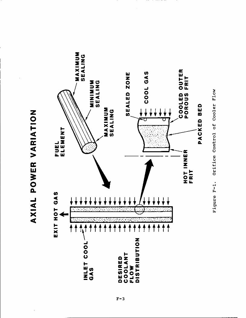
o
ßC < >
AC UJ
o
<
u z o N o u _i < u CO
0) < o _l o o o
WHW
St 3flC OIL
0(0 LUD
OK oo
o u m
(0 < o I- o
UJ
MU\U •\^'H,,i\\'.-!^:;,'> ■s'', vM-.^);V■'.'■\-v.y-■> /•■■ ■ '..';■'.>•£,
tntmttmttttttttt o o o I- 111 (0
±o
o
o z m w< - CC_i£0E
UjOjü QUILQ
o rH fa >-l Q)
iH 0 0 U
<H o
o u •p c 0 u 0) Ü
•H iw -H
o
H I
fa a)
tP •H fa
F-3

heated. The heated gas exits the packed bed at the inner (hot) frit and flows into a central outlet plenum. This hot gas is used to drive a turbine/compressor system and, now cooled, is finally returned through an outer plenum to the cold frit. The issue of concern is that aerosol particulate generated through this closed system might clog the frits or the fuel particle interstitial cooling paths. Clogging could increase the pressure drop through the system or alter the flow pattern causing overheating of the fuel particles. In our review we limited our analysis to frit plugging and did not address the potential for blocking the fuel particle interstitial cooling paths. Although our assumption in the frit-plugging analysis was a conservative bound for frit plug- ging, the quantity of particulate needed to cause localized plugging of the interstices is much less than for the frit- plugging case. Our analysis, consequently, provides some insight into the potential for plugging, but it does not represent a worst-case analysis.
F.3 Discussion
Our review focused on two major aspects of the problem: aero- sol generation and transport to the frits. We discuss these two areas below. We also present two simple models for esti- mating the potential impact of frit clogging for several particle sizes and concentrations. Finally, we include a few miscellaneous observations and a summary.
F.3.1 Aerosol Generation
The characteristics of the aerosol source term are of central importance: specific data an both the quantity and size dis- tribution of the generated aerosol are essential for pre- dicting the possibility of frit clogging. As we discuss below, plausible transport mechanisms of carrying degraded fuel particles to the hot frit can be argued, so that the severity of the clogging risk is dominated by the nature of the aerosol source term. Potential particular sources include:
• explosive fragmentation of the fuel particle,
• amoeba failure due to fuel kernal migration along a temperature gradient,
• launch vibration,
• general vibration including vibration associated with operation of the turbine and compressor,
• thermal and mechanical stresses associated with opera- tional cycling,
F-4

• abrasive wear caused by movement of fuel particles in a flowing gas environment,
• corrosive failure of fuel particles,
• fission products released following particle failure.
BNL has explored most of these potential particulate sources and have presented their reasons for believing that the par- ticulate produced will be insignificant. It may turn out that all particulate sources are insignificant and thus far, BNL's assessment of the particulate source term is encouraging. Nonetheless, until long-term testing or operational experience has demonstrated that no unanticipated and significant par- ticulate sources are generated and no plugging or local flow blockage problems occur, the potential for plugging remains an issue. Again, we must emphasize that we do not anticipate a problem, we simply cannot, as yet, dismiss plugging as an issue.
F.3.2 Aerosol Transport to the Frits
We considered two possibilities: (1) that the fuel particles remain tightly packed throughout the element lifetime and (2) that the fuel-particle bed becomes fluidized. In both cases, we postulate plausible transport mechanisms that might lead to clogging of the hot frit. We are particularly con- cerned by the following apparent assumptions by BNL: (1) that a pore can only be clogged by particles larger than the pore diameter, (2) that particulate smaller than the pore diameter will pass through it, and (3) that particulate not stopped by the cold frit will pass through the hot frit.
Particle deposition is a complicated process that is fre- quently dominated by its inherently unsteady nature. Colli- sions between particles and pore surfaces can result from a variety of physical mechanisms, including diffusion, inter- ception, inertial impaction, and electrical migration. In the diffusion regime, for instance, these collisions can occur for particle diameters much smaller than the pore size. Depending on the physical properties of both the particle and pore sur- face, these collisions may or may not be effective (that is, the particles may or may not adhere to the surface) . If the particles do stick, continuous deposition can lead to obstruc- tion of the pore. As with common fibrous filters, the collec- tion efficiency will increase with time. Thus, particulate much smaller than the pore size can eventually obstruct flow through the pore.
F-5

Collection characteristics between the hot and cold frits cannot be easily compared. The difference in pore size was noted by BNL, but other operating differences were not. Sig- nificant increases in the radial velocity can be expected because of the cylindrical geometry of the system and the specific volume increase resulting from fluid heating. Thus, there exists the possibility that a particle that passes through a small pore at low velocity (cold frit) could be collected by a larger pore at a higher velocity (hot frit).
F.3.2.1 Fixed Bed
The transport of aerosols through packed beds is inherently an unsteady process (Reference 2) . Initially, the bed is clean and can be characterized by a certain initial pressure drop and aerosol collection efficiency. For a uniform bed of depth A packed with spherical grains of diameter Dg to a solids fraction aR, the penetration P through the bed (ratio of the concentrations of particles exiting and entering the bed, P = cout/cin) is given by
3a Ar; ln P £— (F-l) in if 2D \
S
where r? is the single-grain capture efficiency (Reference 3) . Single-grain capture efficiencies are available for various flow regimes and deposition mechanisms (References 3 and 4). The single-grain capture efficiency will depend on particle properties (e.g., diameter and density), flow properties (e.g., Reynolds number), and bed properties (e.g., solid frac- tion) . The important fact is that the penetration is not always either one or zero but is a continuous function. Thus, for any set of conditions, a particle size can be found that will penetrate the bed. Thus, until the source term is well characterized, transport through the bed to the hot frit can- not be ruled out.
Resuspension poses a second possible method of particulate transport through the packed bed. Particles that were ini- tially trapped in the bed matrix could resuspend under altered flow conditions, e.g., resulting from pulses or vibrations. Also, the radioactive nature of the fuel-pellet bed environ- ment may have a pronounced effect on the ability of the fuel- pellet bed to retain trapped particles (Reference 5), possibly enhancing resuspension. With time, resuspended particulate could migrate to the hot frit.
F-6

F. 3.2.2 Fluidized Bed
Although the fuel bed begins as a tightly packed matrix, we considered the eventual possibility of fluidization. Fluid- ization could result, for instance, if there were sufficient degradation of the fuel elements to significantly increase the void fraction. The dangers of fluidization are twofold: (1) enhanced migration of particulate through the bed to the hot frit and (2) increased potential for further fuel-pellet erosion. These concerns might be addressed by fixing the bed in a matrix.
F.3.3 Simple Clogging Models
In this section, we present two simple models for estimating the potential for frit clogging. In both models, the fuel element design of B&W has been assumed. Their design for the hot frit is shown in Figure F-2.
In the first model, we consider that an aerosol of diameter Dp is uniformly deposited over the hot frit surface in a layer of depth Ap. For several particle diameters, we calculate the resulting pressure drop as a function of the fraction of fuel that is aerosolized.
F.3.3.1 Model 1
The volume of the pores Vpore in the hot frit can be approx- imated as
V - 2irr.fir_s L , (F-2) pore f f pore
where rf is the frit radius (1.5 cm), firf the frit thickness (0.10 cm) (note that firf«rf) , L the frit length (30.48 cm), and spore
is tne fraction of the frit surface that is open. From the pore arrangement shown in Figure F-2, spore is cal- culated to be 0.4. The total volume of fuel material Vfuei in the fuel element is
V- . - Jr2 - r*la L , (F-3) fuel I o fj g
where r0 is the outer radius of the fuel bed (2.75 cm). The ratio of the pore to fuel volume is
V 2s r_5r^ P°re _ Rore f f . (F-A)
ag(ro * rf) Vfuel
F-7

CHEMICAL VAPOR DEPOSITED TUBE, EDM SLOTTED (APPROX. 10,000)
SLOTS
PRELIMINARY
1.182
APPROX. 12
0.035
0.012
0.020
DIMENSIONS IN INCHES
Figure F-2. Rhenium Hot Frit
F-8

Assuming a solids fraction of ag = 0.6, this ratio is 0.038. Thus, a complete obstruction of the frit could be obtained under these conditions with only a moderate amount of fuel degradation.
This model is offered primarily for illustrative purposes. The assumption that all of the aerosol is preferentially collected within the pores is not physically reasonable, par- ticularly with a solids fraction of 1. Had the ratio been significantly larger, concerns over frit plugging would have been significantly diminished. However, we feel that the present ratio is small enough to warrant further analysis.
F.3.3.2 Model 2
For this model, we assume that the aerosol generated by fuel degradation is deposited in a uniform layer over the entire hot frit surface to a depth Ap. The particles are assumed to be monodisperse (all of the same size) with diameter Dp. This aerosol layer is porous and will be assumed to have a solids fraction ag = 0.6 independent of particle size (typical for spherical packings). We are interested in estimating the pressure drop through this layer.
The pressure drop AP per unit depth through a bed of spheres of diameter Dp packed to a depth of Ap can be approximated by the Ergun equation:
M, QS . -° [ 150a £_+1.75pv] , (F-5) Ap (l - «J3 Dp I g Dp °J
where V0 is the approach velocity (velocity the fluid would have in the absence of particles) and n and p are the fluid viscosity and density (Reference 6) . Assuming that the working fluid is helium at 1500 K and 2.7 x 10? dyne/cm2 (26.6 atm) , then A» = 5.7 x 10'4 g/cm/s and P = 8.4 x 10"4
g/cm3. We assume a solids fraction ag = 0.6 for all diameters and use an approach velocity of 400 cm/s. Using these values, we calculate the pressure drop per unit depth given in Table F-l.
It would be more convenient to put these results in terms of pressure drop per amount of fuel degradation. To do this, first take the ratio of the volume of the fine particle layer Vfine to the total volume of fuel Vfuei (assuming the Ap«rf) :
V.. IKTJL a L fine r i ~
fuel * r I o
(F-6)
F-9
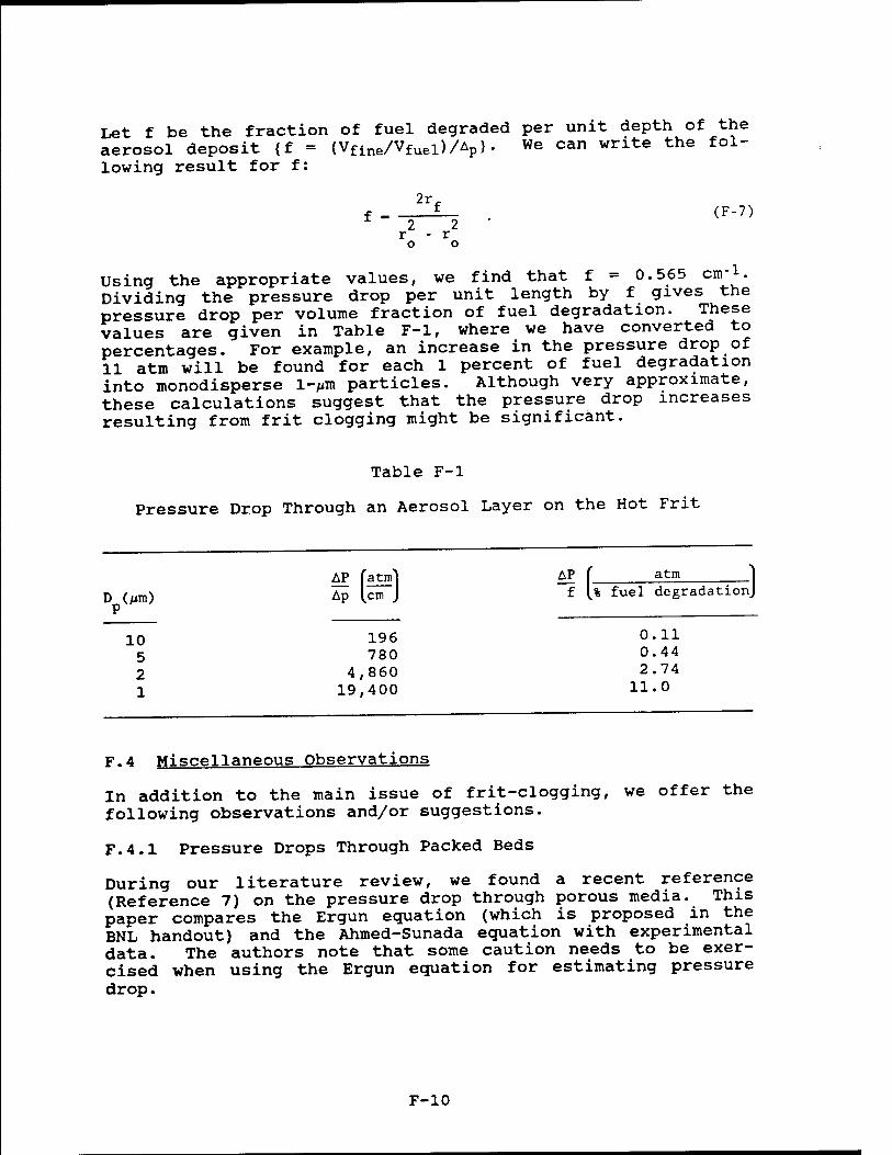
Let f be the fraction of fuel degraded per unit depth of the aerosol deposit {f = (Vfine/Vfuei)/Ap>.
We can write the f°1_
lowing result for f:
f . (F-7) 2 2
r - r o o
Using the appropriate values, we find that f = 0.565 cm1. Dividing the pressure drop per unit length by f gives the pressure drop per volume fraction of fuel degradation. These values are given in Table F-l, where we have converted to percentages. For example, an increase in the pressure drop of 11 atm will be found for each 1 percent of fuel degradation into monodisperse l-/iitt particles. Although very approximate, these calculations suggest that the pressure drop increases resulting from frit clogging might be significant.
Table F-l
Pressure Drop Through an Aerosol Layer on the Hot Frit
D (jim) Ap [cni J f l% fuel <*egradat
P
10 5
AP [atm] Ap [cm J
196 780
4 ,860 19 ,400
AP f atm "j ionj
0.11 0.44
2 4,860 2.74 1 19,400 11.0
F.4 Miscellaneous Observations
In addition to the main issue of frit-clogging, we offer the following observations and/or suggestions.
F.4.1 Pressure Drops Through Packed Beds
During our literature review, we found a recent reference (Reference 7) on the pressure drop through porous media. This paper compares the Ergun equation (which is proposed in the BNL handout) and the Ahmed-Sunada equation with experimental data. The authors note that some caution needs to be exer- cised when using the Ergun equation for estimating pressure drop.
F-10

F.4.2 Aerosol Deposition In Unprotected Areas
Besides the frits and the fuel bed, particle deposition could also occur on any surface within the flow system. There is evidence in the literature that enhanced deposition of radio- active aerosols can occur (Reference 5)- as a result of parti- cle self-charging (Reference 8). In light of the radioactive nature of such deposits, care should be taken to protect mech- anical or electrical components from this source of radiation.
F.5 Summary
We feel that further tests need to be performed before a "yes or no" answer can be given to the frit-clogging issue. The quantity and size distribution of the aerosol source term are the key issues, and we feel that this information must come from experimental testing. With such data in hand, further analysis could be done using the packed-bed theory in the literature. Modeling would be complicated, however, by fac- tors such as the high temperatures, cylindrical geometry, and radioactive nature of the aerosol and environment. With this in mind, the best avenue to pursue might be a testing program that includes the frit-clogging issue.
We would strongly encourage the use of filters upstream of the cold frit. We believe that these could be used effectively at the temperatures likely to be encountered (900 K) with minimum pressure drop. A method of filtering an aerosol downstream of the hot frit would reduce erosion rates and minimize depo- sition throughout the system, but finding a serviceable filter medium at such high temperatures might be difficult.
One additional recommendation would be to include a particle concentration diagnostic in the fuel design. Reasonably small, inexpensive units are available that can monitor both particle concentration and size. This would provide valuable operating data during the lifetime of the device.
F-ll

F. 6 References
1. J. R. Powell, et al., particle Bed Reactor Multimegawatt Concepts. Brookhaven National Laboratory, March 1987.
2. S. A. Walata, T. Takahashi, and C. Tien (1986) "Effect of Particle Deposition on Granular Aerosol Filtration," Aero- sol Science and Technology. 5, pp. 23-37.
3. T. D. D'Ottavio and S. L. Goren (1983), "Aerosol Capture in Granular Beds in the Impaction Dominated Regime, Aero- sol Sei. Technol.. 2, pp. 91-108.
4. H. Pendse and C. Tien (1982), "General Correlation of the Initial Collection Efficiency of Granular Filter Beds, ATCHE Journal. 28(4). pp. 677-686.
5. B. R. Fish and R. L. Walker, Aerosol Physics of Radio- active Particles. Report No. ORNLP-1313, 1965.
6. R. R. G. Eckert and R. M. Drake, Jr., Analysis of Heat and Mass Transfer. (New York: McGraw-Hill, 1972).
7. I. F. Macdonald, M. S. El-Sayed, K. Mow, and F. A. L. Dullien (1979), "Flow Through Porous Media - The Ergun Equation Revisited," Ind. Eng- Chem. Fundam., 18(3), pp. 199-208.
8. H. C. Yeh, G. J. Newton, 0. G. Raabe, and D. R. Boor (1979), "Self-Charging of 198Au-Labeled Monodisperse Gold Aerosols Studied With a Miniature Electrical Mobility Spectrometer," J. Aerosol Sei.. 7, pp. 245-253.
F-12

APPENDIX G
ASSESSMENT OF THE NERVA REACTOR
D. Dobranich D. R. Gallup
A. C. Marshall
G-l

G.l introduction
As our evaluation neared completion, it became clear that the NERVA derivative reactor was a strong candidate for burst-mode operation. In order to be sure that our conclusions regarding the performance of the NERVA reactor were valid, two indepen- dent reviewers (Dean Dobranich and Don Gallup) were assigned to review the NERVA test results. Dobranich was asked to provide a brief overview, and Gallup was asked to review the later tests in greater detail. In addition staff members associated with NERVA at Westinghouse, Los Alamos National Laboratory (LANL) and the DOE (currently at DOE) were con- sulted. Our conclusion that the NERVA reactor demonstrated successful operation for conditions in excess of expected burst-mode SDI requirements was verified. Dobranich s and Gallup's reviews follow.
G.2 Assessment of the NERVA Reactor Tests (D. Dobranich)
Between 1959 and 1972, a series of tests was conducted with the goal of developing a nuclear rocket engine, referred to as the NERVA reactor. The following question with_regard to the NERVA reactor had been posed: Was there sufficient experi- mental evidence to indicate that the NERVA reactor can be successfully used for MMW power in burst-mode ope™**™' (Burst-mode criteria are exit coolant temperature between 1200 and 2000 K, 12 to 20 restarts, and total operating time of 15 to 45 minutes.) I have made a cursory review of the available data in an attempt to address this question; the results of this review are summarized in this section.
The NERVA test results indicate that initially there was a problem related to the loss of graphite element material to the hydrogen coolant. Two mechanisms by which this loss occurred were identified: diffusion through the coolant chan- nel coating and cracking of the coating The coating (either NbC or ZrC) was applied to the coolant channels of the fuel elements using a chemical vapor deposition (CVD) technique. The purpose of the coating was to prevent corrosive inter- action between the graphite and the hydrogen coolant which would lead to loss of graphite material and subsequent loss of element integrity.
Diffusion of qraphite through the coating occurred predomi- nancy a? the exit of the reactor (termed the «hot end») where the coolant temperature was highest. For coolant temperatures below about 2000 K, diffusion was not a problem. sJ^ral changes in the element coating process were made that.essen- tially eliminated the hot-end diffusion. These changes included minor increases of the coating thickness, «»Proved deposition techniques, and an increase in the temperature at: which the coating was applied.
G-2

The more serious graphite loss problem involved the second mechanism, in which graphite diffused through cracks in the coating. This problem occurred predominantly in a region about one-third of the core length away from the core entrance. At this location, termed the midrange region, dif- fusion was not a problem because of the lower coolant tem- peratures. However, the lower coolant temperature, in conjunction with the higher local power density in this region, resulted in the most severe temperature gradient across the fuel element. This radial temperature gradient gave rise to stresses that were sufficient to crack the coating, thereby allowing graphite to escape to the coolant. Cracks were also formed during the CVD process itself as the coating cooled from its deposition temperature.
As the NERVA tests proceeded, changes in the coating procedure were made that reduced the cracking problem. These changes included thinner coatings in the midrange region, variation of the CVD temperature to control crack size and to improve adhe- sion, the use of molybdenum overcoat to fill in microcracks formed during cooling of the applied coating, radial power flattening via orificing and enrichment zoning to reduce ther- mal stresses, and producing graphite with a coefficient of thermal expansion that matched that of the coating. By the end of the NERVA development program, the rate of graphite loss from the elements had been reduced by a factor of 10. For operation at full power for about 110 minutes, tests in the nuclear furnace (a NERVA experimental facility) resulted in graphite mass loss of about 1 percent to 2 percent, com- pared to 10 percent to 20 percent for earlier tests.
After the NERVA program ended, Westinghouse continued to refine the fuel and coating materials to the point that graph- ite loss was insignificant. Given the fact that the burst- mode operating criteria are somewhat less severe than those to which the NERVA reactors were designed, it seems that a suc- cessful fuel development effort for MMW power reactors is essentially complete. At the very least, the major problems have been identified, and reasonable solutions to the problems have been demonstrated.
Some structural problems were associated with the Peewee-1 test, which tool place near the end of the NERVA program. After more than three hours of operation at power levels above 1 MW (4 0 minutes at 503 MW) , the experiments were ended because parts of the unfueled filler elements were observed to be exiting the reactor. The reasons for the partial core breakup were determined to be related to design oversights or fabrication mistakes. The design problems were solved and were to be tested in Peewee-2; however, the NERVA program was terminated before the tests were initiated. One should remem- ber that Peewee-1 was a research reactor designed primarily
G-3

for fuel testing, and the failed hardware was associated with Ihl test befand not the fuel or other "standard" NERVA com- ponent!! The NRX series of tests, however, were technology demonstration tests intended to test the ^""»f °* s£: tem. NRX-A6, the last of the NRX series, successfully ran for 60 minutes at 1125 MW with an exit coolant temperature of 2280 K Although minor hardware problems were encountered, the reactor remained intact.
To summarize, the major problems identified with the NERVA fuel have been solved. Some minor structural Problems were observed even for successful tests such as the NRX-A6 test but these problems did not compromise the reactor. The NERVA program has already identified and solved many of these prob lems. Throughout the entire 13-year Rover program that led to the NERVA reactor, there were approximately 20 reactors built and tested. Many of the tests uncovered flaws in some part of ?he system and ended in failure of the facility; sometimes the failures were very dramatic.
However, such failures are to be expected in such an ambitious development program. Based on my review and interpretation of ?hravailabledata, there is sufficient experimental evxdence to indicate that a NERVA derivative reactor can be success- fully used for a MMW power reactor in burst-mode operation (see References 1 through 7).
G.3 Tip-view of NERVA T^-st Program (P. R. Gallup)
During the Rover Program, which lasted from 1955 to 1972, prob^ms were encountered with several of the reactors during testing? Early in the program, there were serious problems encountered in several of the Kiwi tests. In the middle to ?ater stages of the program, there were problems encountered during the9 NRX-A5 and^elwee-l tests. However, reactor demon- stration tests conducted at the end of the program such as NRX-A6 and the Nuclear Furnace-1, were very successful.
G.3.1 Kiwi
Late in 1962, the Kiwi-BIB and Kiwi-B4A reactors, upon which the NERVA design was based, experienced severe core damage durina testing; parts of several fuel modules were ejected ?rom ?he Sore It was determined that the cause of the core damage was vibration induced by the flow of the hydrogen coSlant.This problem was eliminated in all subsequent tests by a design change in the lateral support system of the reac tor core
G-4

G.3.2 NRX-A5
In 1965, the second full-power test of the NRX-A5 reactor was terminated prematurely, because of excessive loss of reac- tivity (about $2.5). A post-mortem examination of the fuel elements showed that midrange corrosion of the fuel elements was the primary cause of the reactivity loss. The NERVA fuel elements have a hexagonal cross section and contain 19 coolant channels. After the elements are formed, they are coated with NbC (or ZrC) using CVD to prevent corrosion by the hydrogen coolant. However, during cooling after the CVD process, cracks form in the coating. The midrange corrosion during the NRX-A5 test occurred when hydrogen coolant attacked element coating. To avoid this problem during the NRX-A6 test, the cracks in the NbC coating were filled with a molbydenum over- coat using CVD. This substantially reduced the midrange corrosion. After the NERVA tests were completed, other signi- ficant advances were made in NERVA fuel element technology. Bob Holmon of Westinghouse claims that the latest elements can operate for 10 hours at temperatures above 2000 K without significant corrosion.
G.3.3 Peewee-1
In 1968, the third full-power test of the Peewee-1 reactor was terminated prematurely, because pieces of graphite filler elements, which surround the core, were ejected from the reac- tor. The subsequent, post-mortem examination of the core found significant breakage of the filler elements as well as severe corrosion and breakage of some fuel elements and breakage of a significant number of support elements. The reasons for the various types of core damage are complicated. They will be described briefly here; more detailed explana- tions can be found in "Peewee-1 Reactor Test Report" (LA-4217- MS, June 1969).
The core of Peewee-1 consisted of fuel and support elements in 3:1 ratio. These elements were surrounded by graphite filler elements, pyrographite strips, and cooled graphite strips. The purpose of these components was to make the core cross section circular. The core could then be retained radially by garter springs, impedance rings, the core blocking ring, and hot-end ring. The breakage of the core filler elements was the result of two mechanical problems in the core: an improp- erly designed hot-end seal and improperly sized impedance rings. The purpose of the hot-end seal was to allow thermal expansion of the core in the axial direction while preventing the flow of hydrogen around the core. However, this caused axial stresses in the filler elements. Further, the impedance rings were to small, and they caused unexpectedly high radial pressure on the core when it heated up. These two mechanical stresses caused the filler elements to break during the
G-5

earlier runs of Peewee-1. Pieces of the filler elements were then ejected from the core during the third full-power test.
Some of the fuel elements in the Peewee core suffered substan- tial damage—4 6 of the 402 elements were broken or badly cor- roded and could not be weighed during disassembly. Also, many of the elements suffered from relatively high amounts of midrange corrosion. The conditions of the fuel elements can be explained by the operating conditions in the core and by the fact that the elements were experimental. The elements that suffered the roost severe corrosion and breakage were located at the core periphery. This damage was caused pri- marily by the severe thermal gradients present there; tne temperature at the edge of the core was 300 K (550 R) higher than at the center of the core. This was caused by unexpec- tedly high fluxes at the core periphery. The high thermal gradients caused two major problems: (1) fuel elements broke because of high thermal stresses, and (2) the fuel elements separated, which allowed hydrogen to flow between them and resulted in a high amount of external element corrosion. In addition to the elements that suffered severe damage, most of the elements suffered from a relatively high amount of midrange corrosion. This is because all of the fuel elements were experimental: different coatings and coating processes were being investigated and only a few of the elements had a molybdenum overcoat. The elements that did have an overcoat had substantially less midrange corrosion. (See the NRX-A5 discussion.)
Half of the Peewee-1 support elements were fractured during the reactor tests. These fractures were the result of poorly designed seals on the inlet end of the element. The axial motion of the liner tube with respect to the support element was enough that the seal would move past the portion of the liner tube that had a reduced diameter. As a result, during the test, hydrogen flowed through the gap between the liner tube and ZrH17 moderator. This resulted in mechanical damage at the cold end of the support elements and mechanical and corrosion damage at the hot end.
The majority of the problems that occurred during the Peewee-1 reactortest were the result of poor design. Filler elements were broken and ejected from the core, because the hot-end seal stuck during reactor cooldown. The peripheral fuel elements broke and suffered high external corrosion because of unexpectedly high thermal gradients. Many of the support elements broke because of improperly designed inlet seals. Consequently, had the Peewee-2 reactor test been Performed it could have avoided many of the problems encountered during Peewee-1 by using a better reactor design.
G-6

G.3.4 NRX-A6
The NRX-A6 test in 1967 was the last and most successful of the NERVA reactor tests. Its success is due mainly to an improvement made in the reactor fuel. A problem with midrange corrosion had occurred in all of the previous NERVA tests (NRX-A1 through NRX-A5). In fact, the problem got worse with each test; the corrosion rate increased from 0.2 to 0.9 grams per minute per element from A2 to A5. This corresponded to reactivity loss rates of 3.5 to 7.4 cents per minute, respec- tively. The reactivity loss in A5 was so serious that the test was terminated prematurely. As a result, the A6 test was delayed so that the problem with midrange corrosion could be addressed.
The problem of midrange corrosion resulted from the way that the NERVA fuel elements were manufactured. The carbon fuel elements were given an NbC coating to prevent the hot hydrogen coolant from corroding the carbon in the elements. The NbC coating was applied at 1900 K using CVD. However, since NbC has a higher coefficient of thermal expansion than the ele- ment, cracks formed in the coating during the cooling process. During operation, the fuel elements were at approximately 1600 K in the midrange. As a result, the cracks in the NbC coating did not close, and the hydrogen chemically attacked the ele- ments through these cracks and formed methane, CH4. The rate of corrosion was aggravated by the fact that the midrange was the region of highest power density, and so the thermal stresses were the highest in this range.
The solution to the midrange corrosion problem was to apply an overcoat over the NbC coating. This overcoat filled in the cracks in the coating and reduced the midrange corrosion by a factor of 10 and the overall element corrosion by a factor of 5. THe reactivity loss rate was 1.0 cent per minute and the mass loss rate was 0.19 g per minute per element.
As a result of the improved fuel technology, the NRX-A6 reac- tor test was very successful. It operated at 1125 MWth for 60 minutes with a coolant exit temperature at or above 2280 K. This met or exceeded all of the objectives of the NERVA pro- gram.
G.3.5 Nuclear Furnace-1
Nuclear Furnace-1 (NF-1) was a small test reactor with a low fuel inventory that was devised to provide an inexpensive means of testing fuel elements and other core components. It was a heterogeneous, water-moderated, beryllium-reflected reactor that contained 49 cells in which a single NERVA fuel element could be tested. (In contrast, the Peewee core con- tained 420 fuel elements and the NERVA reactors contained 1200 elements.)
G-7

A wide variety of fuels were tested in NF-1. Twenty-four of the fuel cells contained 19-hole (U,ZrC)C-carbon (composite) fuel elements that were built in 1970, twenty:three cells contained newer, composite elements that were built in 1971 and two contained a seven-element cluster of (U,Zr)C (carbide) fuel elements. The carbide elements were smaller and had a sinqle, large coolant channel (similar to the PLUTO geometry). All of the elements were coated with ZrC rather than NbC. Most of the elements had unique features, e.g., various grades of qraphite used in an attempt to produce elements with crack- free ZrC coatings. The NF-1 operated for about 160 minutes, most of that time at an exit temperature of 2450 K.
Some very interesting results were obtained with the NF-1 experimental fuel. The newer composite fuel did riot have cracks in its ZrC coating, whereas the older fuel did. As a consequence, the midrange corrosion in the newer elements was less than one-third the corrosion in the older elements. The average midrange mass loss for the newer elements was 8.6 g. The elements from one of the processes had midrange losses of onlv 5.5 (0.039/min). Another interesting result is that the hot-end losses were less than half of the expected losses. The carbide elements did not perform as well as the composite elements; they all suffered from extensive cracking. However, this is not necessarily a problem with carbide fuel; it could be a problem with the geometry of the carbide elements.
G.3.6 Conclusions
Over the course of the NERVA Program, problems were encoun- tered during several of the reactor tests. The most notable of these were the tests of the Kiwi-BIB, Kiwi-B4A NRX-A5, and Peewee-1 reactors. The Kiwi problems were resolved, and solu- tions to the Peewee-1 problems were found. However■, only the NRX-A5 reactor was a NERVA reactor, and only the NRX-A5 test results have a direct bearing on NERVA technology. The prob- lems identified for NRX-A5 were overcome during the NRX-A6 test. The NRX-A6 and NF-1 nuclear reactor test were two of the most successful tests in the NERVA Program. The NRX-A6 met or exceeded all of the goals of the NERVA program: it ran at a power of 112 5 MWth for 60 minutes with a coolant exit temperature of 2280 K or greater. The NF-1 test in 1972 pro- vided valuable experimental data for developing advanced NERVA fuels.
It is my opinion that NERVA technology is very well developed and that NERVA derivative reactors are strong candidates for MMW burst-mode power sources.
G-8

G.4 References
1. Peewee-1 Reactor Test Report. LA-4217-MS, August 29, 1969.
2. Technical Summary Report of NERVA Program Phase I NRX & XI Volume II. NERVA Component Development and Testing, TNR- 230, July 15, 1972.
3. Technical Summary Report of NERVA Program Phase I NRX & XE Volume III Full Scale Test Programs. TNR-230, July 15, 1972.
4. Technical Summary Report of NERVA Program Phase I NRX & XE Volume IV. Technology Utilization Survey. TNR-230, July 31, 1972.
5. Technical Summary Report of NERVA Program Phase I NRX & XE Volume V. Abstracts of Significant NERVA Documentation. TNR-230, September 1972.
6. Nuclear Furnace-1 Test Report. LA-5189-MS, Informal Report, March 1973.
7. D. Koenig, Experience Gained from the Space Nuclear Rocket Program fRover). LA-10062-H, UC-33, May 1986.
8. NRX-A6 Final Report. TNR-224, January 1969.
G-9

APPENDIX H
RETRIEVABILITY OF NERVA REACTOR TECHNOLOGY
S. L. Hudson
H-l
On November 11, 1986, Steve Hudson and Al Marshall visited the Westinghouse Advanced Energy Systems Division (AESD) in Pittsburgh, PA, to assess the retrievability of NERVA tech- nology. The associated meeting was most informative, with several Westinghouse personnel, all of whom were involved in the NERVA program, giving presentations. From this infor- mation exchange, it was concluded that the NERVA technology is well documented, retrievable to over 90 percent confidence, and that program technical continuity could still exist if follow-up NERVA derivative work were initiated.
The NERVA technology development program was carried out from 1961 to 1971 by Westinghouse Astronuclear Laboratory (now Advanced Energy Systems Division), Aerojet-General Nuclear Systems Company, and Los Alamos Scientific Laboratory (now Los Alamos National Laboratory [LANL]). Westinghouse had primary responsibility for the reactor while Aerojet-General was involved with the rocket nozzle and turbopump. LANL contri- buted to the early experimental program phase. During this period, approximately 20 reactor ground tests were performed on seven derivative reactor concepts at a cost of approx- imately $1.4 billion (although Westinghouse indicated their portion for reactor development was $662 million). Reactor chamber temperatures during these tests exceeded 2400 K, and run times approached one hour.
NERVA technology retrievability was judged high, based on the availability of fabrication drawings, Process Specifications, Purchasing Department Specifications, and several key per- sonnel. In addition, Westinghouse claimed that most documents and reports of the program are available in the Westinghouse corporate storage vault (not visited) in Pittsburgh. The fabrication drawings for the NRX-A6 reactor were still stored onsite at AESD in microfilm form on properly ordered aperture cards. These drawings included material lists, assembly drawings and more than 750 component drawings, all essentially to current DOD 1000 standards (which means present-day machine shops could readily interpret them). An impromptu check of their files showed traceability from assembly drawings through component fabrication drawings and specifications. The Pro- cess Specifications and Purchasing Department Specifications, as referenced from the fabrication drawings, were also on file at AESD. The former type of specification covers fabrication methods, while the latter is concerned with material requi- sition. From my cursory look at these specification files, I think some updating and reference to existing ASTM, ASME, and ANSI codes might be appropriate. Several thousand drawings and a few hundred specifications were estimated to be stored at AESD. Although many persons have left Westinghouse since the days of NERVA 20 years ago (through normal attrition and retirement), a significant number of personnel are still available who were deeply involved in the NERVA program. If a derivative reactor program were initiated in the next few
H-2

years, these people could still provide continuity from this past work that would further enhance the available documen- tation.
During the NERVA program, all fabrication work, except for the extruded graphite fuel elements, was contracted outside of Westinghouse. It is anticipated that no technical problems would prevent this fabrication today and that extruding graphite is existing technology even outside Westinghouse. Further, the fuel particles dispersed within the graphite fuel elements have been developed by several manufacturers since the NERVA program, although ZrC-coated particles are still in the experimental phase.
Finally, most of the computer analysis codes and models for stress, heat-transfer, and fluid flow calculations used in the NERVA program were documented only in reports and do not pres- ently exist as operating programs. Thus, although retriev- ability may be in question here, it is important to realize that far more powerful codes and analysis techniques could be used today, and no significant technology loss is anticipated.
In conclusion, the NERVA technology is not lost, is retriev- able, and could provide a substantial technical base for a derivative burst-mode reactor.
H-3

DISTRIBUTION
Capt. Jerry Brown AFAT/SAS Fort Walton Beach, FL 32542
Lt. Col. J. P. Joyce AFISC/SNAR Kirtland Air Force Base New Mexico 87117
G. Beale AF Astronautics Laboratory/LKCJ Edwards Air Force Base California 93523
F. Meade AF Astronautics Laboratory/LKCJ Edwards Air Force Base California 93523
Lt. R. Henley AF Astronautics Laboratory/LKCJ Edwards Air Force Base California 93523
W. Borger AFWAL/POO Aeronautical Laboratory Wright-Patterson AFB Ohio 45433
P. Colegrove AFWAL/POOA Aeronautical Laboratory Bldg. 18 Wright-Patterson AFB Ohio 45433
D. Massie AFWAL/P00C-1 Aeronautical Laboratory Bldg. 450 Wright-Patterson AFB Ohio 45433
C. Oberly AFWAL/POOC-1 Aeronautical Laboratory Wright-Patterson AFB Ohio 45433
Major E. Houston AF Astronautics Laboratory/LKCJ Edwards Air Force Base California 93523
Dick Renski AFWAL/AA Wright-Patterson AFB Ohio 45433
E. B. Kennel AFWAL/POOS Wright-Patterson AFB Ohio 45433
J. Beam AFWAL/POOS Wright-Patterson AFB Ohio 45433
R. Thibodeau AFWAL/POOC-1 Bldg. 450 Wright-Patterson AFB Ohio 45433
T. Mahefky AFWAL/POOC-1 Aeronautical Laboratory Wright-Patterson AFB Ohio 45433
AFWAL/POOC-1 Power Components Branch Wright-Patterson AFB Ohio 45433-6563
Major Seward AFWAL/POOC Aeronautical Laboratory Bldg. 18 Wright-Patterson AFB Ohio 45433
M. J. Schuller AFWL/AFSC Kirtland Air Force Base New Mexico 87117
Dist-1

D. Kelleher AFWL/AW Kirtland AFB New Mexico 87117
Lt. Col. D. R. Boyle AFWL Kirtland Air Force Base New Mexico 87117
Lt. Col. F. Lawrence HQ AFSPACECOM/XPXIS Peterson Air Force Base Colorado 80914-5001
Maj. P. Talty HQ USAF/RD-D Washington, DC 20330-5042
W. Zelinsky Aerospace Corporation P. 0. Box 9113 Albuquerque, NM 87119
W. Blocker Aerospace Corporation P. 0. Box 9113 Albuquerque, NM 87119
M. Firmin Aerospace Corporation P. 0. Box 9113 Albuquerque, NM 87119
P. Margolis Aerospace Corporation P. 0. Box 92957 El Segundo, CA 90009
W. Barattino, AFCSA/SASD Air Force Center for Studies
and Analyses/SASD The Pentagon, Room ID-431 Washington, DC 20330-5420
B. L. Ballard Air Force Foreign Technology Div. TQTD Wright-Patterson AFB Ohio 45433-6563
K. W. Hoffman Air Force Foreign Technology Div. TQTD Wright-Patterson AFB Ohio 45433-6563
J. DiTucci Air Force Space Technology Center SWL Kirtland AFB, NM 87117-6008
S. Peterson Air Force Space Technology Center SWL Kirtland AFB, NM 87117-6008
M. Good Air Force Space Technology Center TP Kirtland AFB, NM 87117-6008
A. Huber Air Force Space Technology Center XLP Kirtland AFB, NM 87117-6008
K. C. Hartkay ANSER Corp. Crystal Gateway 3 1225 Jefferson Davis Highway #800 Arlington, VA 22208
S. Bhattacharyya Argonne National Laboratory 9700 S. Cass Avenue Argonne, IL 60439
D. C. Fee Argonne National Laboratory 9700 S. Cass Avenue Argonne, IL 60439
K. D. Kuczen Argonne National Laboratory 9700 S. Cass Avenue Argonne, IL 60439
R. A. Lewis Argonne National Laboratory 9700 S. Cass Avenue Argonne, IL 60439
Dist-2

D. C. Wade Argonne National Laboratory 9700 S. Cass Avenue Argonne, IL 60439
Dr. T. Hyder Auburn University 202 Sanform Hall Aubom, AL 36849-3501
F. Rose Auburn University 231 Leach Center Auburn, AL 36849-3501
D. W. Swallom AVCO Research Laboratory 2385 Revere Beach Pkwy Everett, MA 02149
E. U. Kahn BDM Corporation 1715 Jones Branch Drive MS West Branch 5B37 McLean, VA 22101
B. J. Short Babcock & Wilcox Nuclear Power Division 3315 Old Forest Road P. 0. Box 10935 Lynchburg, VA 24506-0935
J. 0. Barner Batteile Pacific Northwest Lab. P. 0. Box 999 Richland, WA 99352
L. Schmid Battelle Pacific Northwest Lab. P. 0. Box 999 Richland, WA 99352
E. P. Coomes Battelle Pacific Northwest Lab. P. 0. Box 999 Richland, WA 99352
W. J. Krotiuk Battelle Pacific Northwest Lab. P. 0. Box 999 Richland, WA 99352
R. D. Widrig Battelle Pacific Northwest Lab. P. 0. Box 999 Richland, WA 99352
B. M. Johnson Battelle Pacific Northwest Lab. Battelle Boulevard Richland, WA 99352
A. Sutey Boeing Company P. 0. Box 3999 MS 8K-30 Seattle, WA 98124-2499
K. Kennerud Boeing Company Boeing Aerospace System P. 0. Box 3707 Seattle, WA 98124
T. Bowden Brookhaven National Laboratory P. 0. Box 155 Upton, NY 11973
H. Ludewig Brookhaven National Laboratory P. 0. Box 155 Upton, NY 11973
W. Y. Kato Brookhaven National Laboratory P. 0. Box 155 Upton, NY 11973
J. Powell Brookhaven National Laboratory P. 0. Box 155 Bldg. 701, Level 143 Upton, NY 11973
V. C. Truscello California Inst. of Technology Jet Propulsion Laboratory 4800 Oak Grove Drive Pasadena, CA 91109
Dist-3

P. Banks ton California Inst. of Technology Jet Propulsion Laboratory 4800 Oak Grove Drive Pasadena, CA 91109
E. P. Framan California Inst. of Technology Jet Propulsion Laboratory 4800 Oak Grove Drive Pasadena, CA 91109
L. Isenberg California Inst. of Technology Jet Propulsion Laboratory 4800 Oak Grove Drive Pasadena, CA 91109
J. Mondt California Inst. of Technology Jet Propulsion Laboratory 4800 Oak Grove Drive Pasadena, CA 91109
P. Kemmey DARPA 1400 Wilson Blvd. Arlington, VA 22209
D. C. Sewell DCSCON Consulting 4265 Drake Court Livermore, CA 94550
J. Farber/RAEV Defense Nuclear Agency 6801 Telegraph Road Alexandria, VA 22310-3398
J. Foster DNA/RAEV 6801 Telegraph Road Alexandria, VA 22310-3398
R. Rice EG&G Idaho, Inc./INEL P. 0. Box 1625 Idaho Falls, ID 83415
J. Dearien EG&G Idaho, Inc./INEL P. 0. Box 1625 Idaho Falls, ID 83415
M. L. Stanley EG&G Idaho, Inc./INEL P. 0. Box 1625 Idaho Falls, ID 83415
R. D. Struthers EG&G Idaho, Inc./INEL P. 0. Box 1625 Idaho Falls, ID 83415
J. F. Whitbeck EG&G Idaho, Inc./INEL P. 0. Box 1625 Idaho Falls, ID 83415
P. W. Dickson EG&G Idaho, Inc./INEL P. 0. Box 1625 Idaho Falls, ID 83415
J. W. Henseheid EG&G Idaho, Inc./INEL P. 0. Box 1625 Idaho Falls, ID 83415
V. Pizzuro Ford Aerospace Corporation Aeronutronic Div. Ford Road, P. 0. Box A Newport Beach, CA 92658-9983
H. J. Snyder GA Technologies P. 0. Box 85608 San Diego, CA 92138
C. Fisher GA Technologies P. 0. Box 85608 San Diego, CA 92138
R. Dahlberg GA Technologies P. 0. Box 85608 San Diego, CA 92138
Robert Boyle Garrett Fluid Systems Co. P. 0. Box 5217 Phoenix, AZ
Dist-4

Sam Armijo General Electric Company P. 0. Box 8555 Astro Systems Philadelphia, PA 19101
C. Cowan General Electric Corp./NSTO 310 DeGuigne Drive Sunnyvale, CA 90486
E. E. Gerrels General Electric Corp./NSTO 310 DeGuigne Drive Sunnyvale, CA 90486
H. S. Bailey General Electric Corp./NSTO 310 DeGuigne Drive Sunnyvale, CA 90486
General Electric-SCO P. 0. Box 8555 Astro Systems Philadelphia, PA 19101
J. Hnat General Electric P. 0. Box 8555 Astro Systems Philadelphia, PA 19101
R. D. Casagrande General Electric P. 0. Box 8555 Astro Systems Philadelphia, PA 19101
W. Chiu General Electric P. 0. Box 8555 Astro Systems Philadelphia, PA 19101
J. Belisle Grumman Aerospace Corporation M/S B20-05 Bethpage, NY 11714
D. S. Dutt Hanford Engineering Dev. Lab P. 0. Box 1970 Richland, WA 99352
Tom Weimer House of Representatives Staff Space and Technology Committee 2320 Rayburn Building Washington, DC 20515
W. H. Roack Idaho National Engineering
Laboratory P. 0. Box 1625 Idaho Falls, ID 83414
N. J. Diaz Innovative Nuclear Space Pwr. Inst. 202 NSC University of Florida Gainesville, FL 32611
G. B. Varnado International Energy Assoc. Ltd. 1717 Louisiana NE Suite 202 Albuquerque, NM 87110
Lynn Cleland, MS L-144 Lawrence Livermore National Lab. P. 0. Box 808 Livermore, CA 94550
C. E. Walter, MS L-144 Lawrence Livermore National Lab. P. 0. Box 808 Livermore, CA 94550
T. Trapp, MS-E561 Los Alamos National Laboratory P. 0. Box 1663 Los Alamos, NM 87545
R. Hardie, MS-F611 Los Alamos National Laboratory P. 0. Box 1663 Los Alamos, NM 87545
C. Bell, MS-A145 Los Alamos National Laboratory P. 0. Box 1663 Los Alamos, NM 87545
R. J. LeClaire Los Alamos National Laboratory P. 0. Box 1663 Los Alamos, NM 87545
Dist-5

S. Jackson, MS-F611 L. H. Sullivan Los Alamos National Laboratory Los Alamos National Laboratory
P. 0. Box 1663 P. 0. Box 1663 Los Alamos, NM 87545 Los Alamos, NM 87545
J. Metzger R. Giellis Los Alamos National Laboratory Martin Marietta Corp. P. 0. Box 1663 P. 0. Box 179 Los Alamos, NM 87545 Denver, CO 80201
C. W. Watson, MS-F607 R. Zercher Los Alamos National Laboratory Martin Marietta Corp. P. 0. Box 1663 P. 0. Box 179 Los Alamos, NM 87545 Denver, CO 80201
Don Reid, MS-H811 J. A. Bernard Los Alamos National Laboratory Massachusetts Institute of
P. 0. Box 1663 Technology Los Alamos, NM 87545 1328 Albany Street
Cabridge, MA 02139 R. Bohl, MS-K551 Los Alamos National Laboratory T. Botts P. 0. Box 1663 M.R.J. Inc. Los Alamos, NM 87545 Suite 200
10455 White Granite Drive D. R. Bennett Oaktan, VA 22124 Los Alamos National Laboratory P. 0. Box 1663 Barbara McKissock, MS 301-5 Los Alamos, NM 87545 NASA Lewis Research Center
21000 Brookpark Road W. Rankin Cleveland, OH 44135 Los Alamos National Laboratory P. 0. Box 1663 S. Borowski Los Alamos, NM 87545 NASA Lewis Research Center
21000 Brookpark Road 0. Scott Cleveland, OH 44135 Los Alamos National Laboratory P. 0. Box 1663 A. Juhasz, MS 301-5 Los Alamos, NM 87545 NASA Lewis Research Center
21000 Brookpark Road W. L. Kirk Cleveland, OH 44135 Los Alamos National Laboratory P. 0. Box 1663 J. Smith, MS 301-5 Los Alamos, NM 87545 NASA Lewis Research Center
21000 Brookpark Road M. Merrigan Cleveland, OH 44135 Los Alamos National Laboratory P. 0. Box 1663 H. Bloomfield, MS 301-5 Los Alamos, NM 87545 NASA Lewis Research Center
21000 Brookpark Road T. P. Suchocki Cleveland, OH 44135 Los Alamos National Laboratory P. 0. Box 1663 Los Alamos, NM 87545
Dist-6

C. Purvis, MS 203-1 NASA Lewis Research Center 21000 Brookpark Road Cleveland, OH 44135
D. Bents, MS 301-5 NASA Lewis Research Center 21000 Brookpark Road Cleveland, OH 44135
I. Myers, MS 301-2 NASA Lewis Research Center 21000 Brookpark Road Cleveland, OH 44135
G. Schwarze, MS 301-2 NASA Lewis Research Center 21000 Brookpark Road Cleveland, OH 44135
J. Sovie, MS 301-5 NASA Lewis Research Center 21000 Brookpark Road Cleveland, OH 44135
R. Cohen National Research Council Energy Engineering Board Commission on Engineering
and Technical Systems 2101 Constitution Avenue Washington, DC 20418
R. L. Eilbert Naval Research Laboratory Washington, DC 20375-5000
I. M. Vitkovitsky Naval Research Laboratory Washington, DC 20375-5000
Commander R. Nosco Naval Space Command Dahlgren, VA 22448
B. Meyers Naval Space Command Dahlgren, VA 22448
Maj. J. Wiley Naval Space Command N5 Dahlgren, VA 22448
R. Gripshoven-F12 Naval Surface Weapons Center Dahlgren, VA 22448-5000
R. Dewitt-F12 Naval Surface Weapons Center Dahlgren, VA 22448-5000
B. Maccabee Naval Surface Weapons Center White Oak Laboratory MC R-42 Silver Springs, MD 20903-500
R. Weed Nichols Research Corp. 2340 Alamo Street, SE Suite 105 Albuquerque, NM 87106
J. P. Nichols Oak Ridge National Laboratory P. 0. Box Y Bldg. 9201-3, MS-7 Oak Ridge, TN 37831
D. Bartine Oak Ridge National Laboratory P. 0. Box Y Bldg. 9201-3, MS-7 Oak Ridge, TN 37831
R. H. Cooper, Jr. Oak Ridge National Laboratory P. 0. Box Y Bldg. 9201-3, MS-7 Oak Ridge, TN 37831
J. C. Moyers Oak Ridge National Laboratory P. 0. Box Y Bldg. 9201-3, MS-7 Oak Ridge, TN 37831
M. Olszewski Oak Ridge National Laboratory P. 0. Box Y Bldg. 9201-3, MS-7 Oak Ridge, TN 37831
Dist-7
M. Siman-Tov Oak Ridge National Laboratory P. 0. Box Y Bldg. 9201-3, MS-7 Oak Ridge, TN 37831
F. W. Wiffen Oak Ridge National Laboratory P. 0. Box Y Bldg. 9201-3, MS-7 Oak Ridge, TN 37831
H. W. Hoffman Oak Ridge National Laboratory P. 0. Box X Oak Ridge, TN 37831
R. Gray RADC/OCTP Griffiss AFB New York 13441
J. Feig Riverside Research Institute 1701 No. Ft. Meyers Drive Suite 700 Arlington, VA 22209
R. M. Hansen Rockwell International 6633 Canoga Avenue Canoga Park, CA 91303
P. Mast Science Applications, Inc. 505 Marquette Avenue NW Albuquerque, NM 87102
G. L. Zigler Science & Engineering Associates 6301 Indian School Road, NE Albuquerque, NM 87110
R. Verga SDI Organization The Pentagon Washington, DC 20301-7100
D. Buden SDI Organization The Pentagon Washington, DC 20301-7100
C. Northup SDI/SLKT The Pentagon 1717 H. St. NW Washington, DC 20301
Dr. J. Hammond SDIO/DE Washington, DC 20301-7100
Dr. L. Cavery SDIO/IST Washington, DC 20301-7100
Col. R. Ross SDIO/KE The Pentagon Washington, DC 20301-7100
Maj. R. X. Lenard SDIO/KE The Pentagon Washington, DC 20301-7100
Col. Garry Schnelzer SDIO/SATKA Washington, DC 20301-7100
Dr. C. Sharn SDIO/SY Washington, DC 20301-7100
Col. J. Schofield SDIO/SY Washington, DC 20301-7100
Col. J. Graham SDIO/SY Washington, DC 20301-7100
Capt. J. Doegan SDIO/SY Washington, DC 20301-7100
J. R. Wetch Space Power, Inc. 253 Humbolt Court Sunnyvale, CA 94089
Jim Sargeant State University of New York
at Buffalo Dept. of Elec. Engineering 312 Bonner Avenue Buffalo, NY 14260
Dist-8

R. Hammel TRW One Space Park Redondo Beach, CA 90278
T. Fitzgerald TRW One Space Park Redondo Beach, CA 90278
C. Garner TRW One Space Park Redondo Beach, CA 90278
B. Glasgow TRW One Space Park Redondo Beach, CA 90278
A. D. Schoenfeld TRW One Space Park Redondo Beach, CA 90278
Dan DeLong Teledyne Brown Engineering Cummings Research Park Huntsville, AL 35807
F. Best Texas A&M University Nuclear Engineering Dept. College Station, TX 77843-3133
Dr. W. Portnoy Texas Tech. University Dept. of Electrical Engr. Lubbock, TX 79409
SMCAR-SSA-E U.S. Army ARDC Building 329 Picatinny Arsenal New Jersey 87806-5000
Dr. L. Amstutz-STRABE-FGE U.S. Army Belvoir RDE Center Fort Belvoir, VA 22060-5606
S. Levy U.S. Army Lab. Com. SLKET/ML Pulse Power Technology Branch Fort Monmouth, NJ 07703-5000
N. Wilson U.S. Army Lab. Com. SLKET/ML Pulse Power Technology Branch Fort Monmouth, NJ 07703-5000
C. Cooper U.S. Army Strategic Defense Com. 106 Wynn Drive Huntsville, AL 35807
G. Edlin U.S. Army Strategic Defense Com. 106 Wynn Drive Huntsville, AL 35807
R. Hall U.S. Army Strategic Defense Com. 106 Wynn Drive Huntsville, AL 35807
E. L. Wilkinson U.S. Army Strategic Defense Com. 106 Wynn Drive Huntsville, AL 35807
D. Bouska U.S. Army Strategic Defense Com. 106 Wynn Drive Huntsville, AL 35807
W. Sullivan U.S. Army Strategic Defense Com. 106 Wynn Drive Huntsville, AL 35807
F. King U.S. Army Strategic Defense Com. 106 Wynn Drive Huntsville, AL 35807
J. L. Hooper U.S. Department of Energy Chicago Operations Office 9800 S. Cass Avenue Argonne, IL 60439
Dist-9

J. Warren U. S. Department of Energy NE-521 E419/GTN Germantown, MD 20545
E. Wahlquist U. S. Department of Energy NE-54 F415/GTN Germantown, MD 20545
J. K. Hartman U.S. Department of Energy San Francisco Operations Office 1333 Broadway Ave. Oakland, CA 94612
J. Krupa U.S. Department of Energy SAN - ACR Division 1333 Broadway Oakland, CA 94612
W. Lambert U.S. Department of Energy SAN - ACR Division 1333 Broadway Oakland, CA 94612
J. Zielinski U.S. Department of Energy SAN - ACR Division 1333 Broadway Oakland, CA 94612
G. Staats (PM-20) U.S. Department of Energy Pittsburgh Energy Tech. Center P.O. Box 18288 Pittsburgh, PA 15236
I. Helms U.S. Department of Energy NE-54 Washington, DC 20545
E. E. Hoffman U.S. Department of Energy NE-54 Washington, DC 20545
W. Cook U.S. Department of Energy Washington, DC 20545
J. Hooper U.S. Department of Energy Washington, DC 20545
R. J. Hoyles U.S. Department of Energy Washington, DC 20545
E. E. Lambert U.S. Department of Energy Washington, DC 20545
S. J. Lanes U.S. Department of Energy Washington, DC 20545
J. 0. Lee U.S. Department of Energy Washington, DC 20545
S. L. Samuelson U.S. Department of Energy Washington, DC 20545
E. M. Richardson U.S. Department of Energy Washington, DC 20545
R. Holton U.S. Department of Energy ALO/ETD P.O. Box 5400 Albuquerque, NM 87115
C. Quinn U.S. Department of Energy ALO/ETD P.O. Box 5400 Albuquerque, NM 87115
P. J. Dirkmaat U.S. Department of Energy/Idaho 785 DOE Place Idaho Falls, ID 83402
D. McVay United Technologies International Fuel Cells 195 Governor's Highway South Windsor, CT 06074
Dist-10

J. 1,. Preston, Jr. United Technologies International Fuel Cells 195 Governor's Highway South Windsor, CT 06074
J. C. Trocciola United Technologies International Fuel Cells 195 Governor's Highway South Windsor, CT 06074
A. S. Kumar University of Missouri - Rolla 220 Engineering Research Lab Rolla, MO 65401-0249
M. El-Genk University of New Mexico Chemical and Nuclear Engineering
Department Albuquerque, NM 87131
Gerald Kulcinski University of Wisconsin Fusion Technology Institute 1500 Johnson Drive Madison, WI 53706-1687
P. Mace W. J. Schäfer Associates 1901 No. Ft. Myers Drive Suite 800 Arlington, VA 22209
S. Bassett W. J. Schäfer Associates 1901 No. Ft. Myers Drive Suite 800 Arlington, VA 22209
M. Nikolich W. J. Schäfer Associates 1901 No. Ft. Myers Drive Suite 800 Arlington, VA 22209
J. Crissey W. J. Schäfer Associates 1901 No. Ft. Myers Drive Suite 800 Arlington, VA 22209
A. K. Hyder W. J. Schäfer Associates 1901 No. Ft. Myers Drive Suite 800 Arlington, VA 22209
D. C. Straw W. J. Schaefer Associates 2000 Randolph Road, SE #205 Albuquerque, NM 87106
J. Chi Westinghouse Electric P.O. Box 158 Madison, PA 15663-0158
J. F. Wett Westinghouse Advanced Energy Systems Division Manager, Space & Defense Program Route 70, Madison Exit Madison, PA 15663
Dr. J. W. H. Chi Westinghouse Advanced Energy Systems Division P.O. Box 158 Madison, PA 15663
J. R. Repp Westinghouse R&D 1310 Beulah Road Bldg. 501-3Y56 Pittsburgh, PA 15235
L. Long Westinghouse R&D 1310 Beulah Road Bldg. 501-3Y56 Pittsburgh, PA 15235
Owen Taylor Westinghouse R&D 1310 Beulah Road Bldg. 501-3Y56 Pittsburgh, PA 15235
G. Farbman Westinghouse Advanced Energy
Systems Division P. 0. Box 158 Madison, PA 15663
Dist-11

D. S. Dutt Westinghouse Hanford Company P. 0. Box 1970 Richland, WA 99352
B. J. Makenas Westinghouse Hanford Company P. 0. Box 1970 Richland, WA 99352
1140 P. S. Peercy 1200 J. P. VanDevender 1240 K. R. Prestwich 1248 M. T. Buttram 1270 J. K. Rice 1271 M. Clauser 1512 J. C. Cummings 1800 R. J. Eagan 1810 D. W. Schaefer 1830 M. J. Davis 1832 W. B. Jones 1832 R. J. Salzbrenner 1840 R. E. Loehman 2110 R. E. Bair 2140 H. J. Saxton, Acting 2150 E. Graham, Jr. 2560 J. T. Cutchen 3141 S. A. Landenberger (5) 3141- 1 C. A. Ward (8) 3151 W. I. Klein (3) 6400 D. McCloskey 6410 D. A. Dahlgren 6420 W. G. Gauster 6422 J. E. Brockmann 6425 S. S. Dosanjh 6450 T. R. Schmidt 6453 J. S. Philbin 6500 A. W. Snyder 6510 J. V. Walker 6512 J. V. Walker, Acting 6512 L. W. Connell 6512 V. J. Dandini 6512 D. Dobranich 6512 E. L. Emerson 6512 R. J. Gross 6512 C. D. Harmon 6512 R. S. Longenbaugh 6512 P. J. McDaniel 6512 C. A. Ottinger 6512 J. Pfarner 6512 L. C. Sanchez 6512 L. R. Shipers
6512 F. J. Wyant 6516 P. S. Pickard 6516 G. A. Harms 6516 S. A. Wright 6520 G. G. Weigand 6521 D. D. Carlson 6522 L. Cropp (10) 6522 D. T. Furgal 6522 D. R. Gallup 6522 S. L. Hudson 6522 A. C. Marshall (20) 6522 W. H. McCulloch 6522 R. E. Pepping 6522 R. R. Peters 6524 W. R. Dawes, Jr. 6524 D. B. King 6524 D. H. Loescher 6524 S. M. Luker 6524 F. V. Thome 6525 D. L. Berry 8400 R. C. Wayne 8524 J. A. Wackerly 9000 R. L. Hagengruber 9010 W. C. Hines 9012 c. C. Carson 9012 R. Zazworski 9100 R. G. Clem 9110 C. W. Childers 9140 D. J. Rigali
■& U.S. GOVERNMENT PRINTING OFFICE: 1989—673-049/81063
Dist-12