a robotic end effector for inspection of storage tanks …/67531/metadc665686/m2/1/high... ·...
TRANSCRIPT

DOE/MC/3 03 63-96/C0627
A Robotic End Effector for Inspection of Storage Tanks
Authors:
Gregory Hughes Mark Gittleman
Con tractor:
Oceaneering Space Systems 16665 Space Center Boulevard Houston, Texas 77058
Contract Number:
DE-AR2 1 -93MC30363
Conference Title:
Environmental Technology Development Through Industry Partnership
Conference Location:
Morgantown, West Virginia
Conference Dates:
October 3-5, 1995
Conference Sponsor:
U.S. Department of Energy, Office of Enviromental Management, Morgantown Energy Technology Center
DISCLAIMER
This report was prepared as an account of work sponsored by an agency of the United States Government. Neither the United States Government nor any agency thereof, nor any of their employees, makes any warranty, express or implied, or assumes any legal liability or responsibility for the accuracy, completeness, or usefulness of any. information, apparatus, product, or process disclosed, or represents that its use would not infringe privately owned rights. Reference herein to any specific commercial product, process, or service by trade name, trademark, manu- facturer, or otherwise does not necessarily constitute or imply its endorsement, recommendation, or favoring by the United States Government or any agency thereof. The views and opinions of authors expressed herein do not necessarily state or reflect those of the United States Government or any agency thereof.
This report has been reproduced directly from the best available COPY.
Available to DOE and DOE contractors from the Office of Scientific and Technical Information, 175 Oak Ridge Turnpike, Oak Ridge, TN 37831; prices available at (615) 576-8401.
Available to the public from the National Technical Information Service, U.S. Department of Commerce, 5285 Port Royal Road, Springfield, VA 22161; phone orders accepted at (703) 487-4650.
,
2.5 A Robotic End Effector for Inspection of Storage Tanks
Introduction
Gregory Hughes ([email protected]; (713) 488 9080) Mark Gittleman ([email protected]; (713) 488 9080)
Oceaneering Space Systems 16665 Space Center Blvd Houston, Texas, 77058
The structural integrity of waste storage tanks is of primary importance to the DOE, and is one aspect of the High-Level Waste Tank Remediation focus area. Cracks andor corrosion damage in the inner tank walls can lead to the release of dangerous substances into the environment. The detection and sizing of corrosion and cracking in steel tank walls through remote non destructive evaluation (NDE) is the primary focus of this work.
Problem
Damaged sites may represent a small proportion of the total inner wall area so, rather than NDE the whole area, more selective and efficient methods of inspection are being developed. The defects of interest can be very small, which implies very accurate deployment of an NDE inspection device. Typically the large manipulators required to access the underground storage tanks (such as the Light Duty Utility Arm) are not designed for such high accuracy.
lResearch sponsored by the U.S. Department of Energy's Morgantown Energy Technology Center, under contract DE-AR21-93MC30363 with Oceaneering Space Systems, 16665 Space Center Blvd, Houston, Texas, 77058; telefax: (713) 488 2027
DISTRIBUTION OF THIS DOCUMENT IS UNLIMITEDd)
b
Soh tion
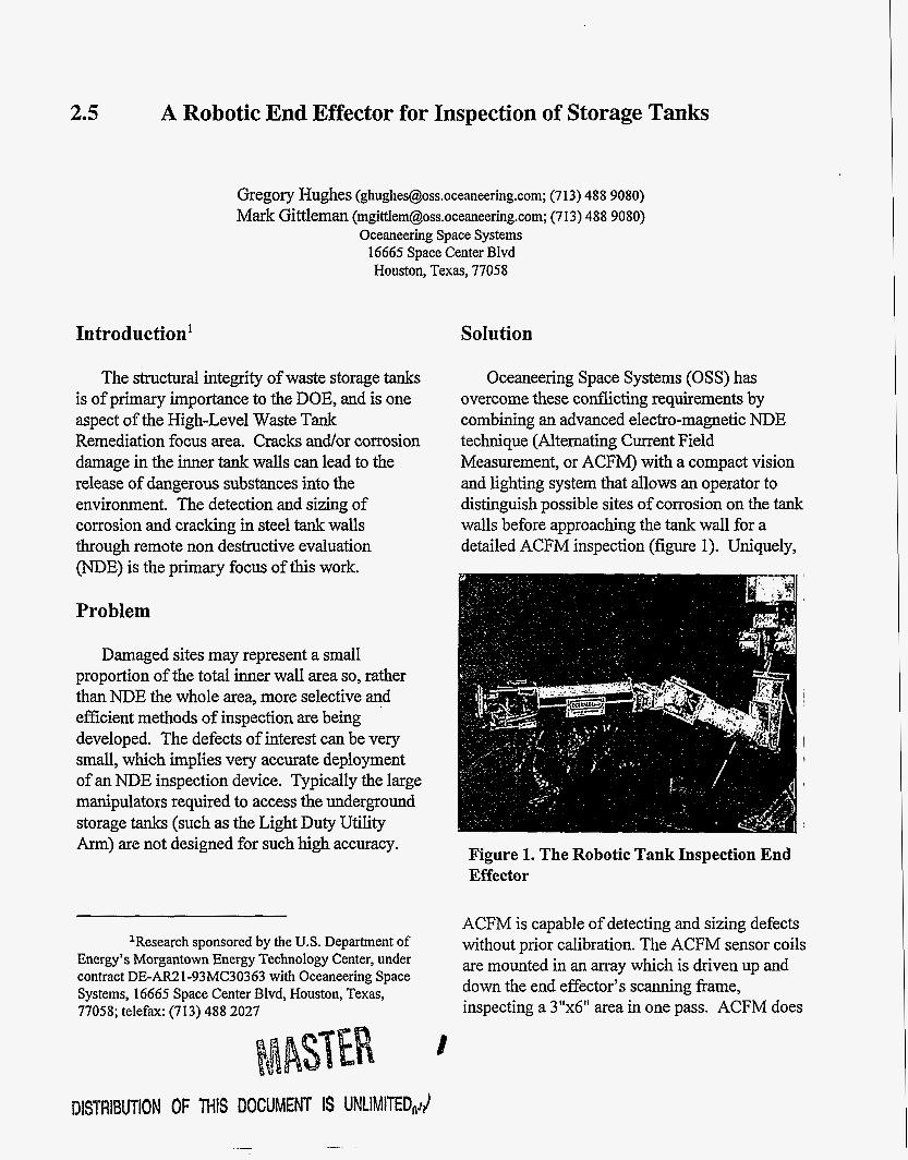
Oceaneering Space Systems (OSS) has overcome these conflicting requirements by combining an advanced electro-magnetic NDE technique (Alternating Current Field Measurement, or ACFM) with a compact vision and lighting system that allows an operator to distinguish possible sites of corrosion on the tank walls before approaching the tank wall for a detailed ACFM inspection (figure 1). Uniquely,
Figure 1. The Robotic Tank Inspection End Effector
ACFM is capable of detecting and sizing defects without prior calibration. The ACFM sensor coils are mounted in an array which is driven up and down the end effector's scanning frame, inspecting a 3"x6" area in one pass. ACFM does
not require direct electrical contact with the tank wall to detect and size defects, nor is it particularly sensitive to standoff or orientation. In addition ACFM does not require coupling fluid, a drawback of ultrasonic inspection techniques in which the couplant becomes secondary waste.
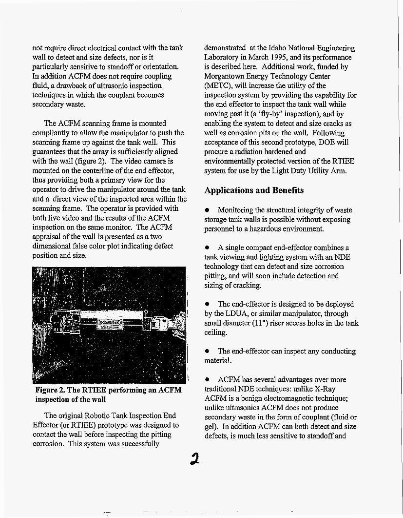
The ACFM scanning frame is mounted compliantly to allow the manipulator to push the scanning frame up against the tank wall. This guarantees that the array is sufficiently aligned with the wall (figure 2). The video camera is mounted on the centerline of the end effector, thus providing both a primary view for the operator to drive the manipulator around the tank and a direct view of the inspected area within the scanning frame. The operator is provided with both live video and the results of the ACFM inspection on the same monitor. The ACFM appraisal of the wall is presented as a two dimensional false color plot indicating defect position and size.
Figure 2. The RTIEE performing an ACFM inspection of the wall
The original Robotic Tank Inspection End Effector (or RTIEE) prototype was designed to contact the wall before inspecting the pitting corrosion. This system was successfully
demonstrated at the Idaho National Engineering Laboratory in March 1995, and its performance is described here. Additional work, funded by Morgantown Energy Technology Center (METC), will increase the utility of the inspection system by providing the capability for the end effector to inspect the tank wall while moving past it (a 'fly-by' inspection), and by enabling the system to detect and size cracks as well as corrosion pits on the wall. Following acceptance of this second prototype, DOE will procure a radiation hardened and environmentally protected version of the RTIEE system for use by the Light Duty Utility Arm.
Applications and Benefits
Monitoring the structural integrity of waste storage tank walls is possible without exposing personnel to a hazardous environment.
0 A single compact end-effector combines a tank viewing and lighting system with an NDE technology that can detect and size corrosion pitting, and will soon include detection and sizing of cracking.
0
by the LDUA, or similar manipulator, through small diameter (1 1 ") riser access holes in the tank
The end-effector is designed to be deployed
ceiling.
0
material. The end-effector can inspect any conducting
0 ACFM has several advantages over more traditional NDE techniques: unlike X-Ray ACFM is a benign electromagnetic technique; unlike ultrasonics ACFM does not produce secondary waste in the form of couplant (fluid or gel). In addition ACFM can both detect and size defects, is much less sensitive to standoff and
a
misorientation than eddy current techniques, and works through most coatings and layers.
Alternating Current Field Measurement (ACFM)
ACFW is an electromagnetic NDE technique that has been specifically developed to overcome the shortcomings of eddy current techniques. ACFM combines the ability of the Alternating Current Potential Drop (ACPD) technique to size defects without prior calibration with the ability of eddy current to work without electrical contact. This is achieved by inducing a uniform AC field in the target material and measuring the magnetic fields above the specimen. The uniform current flow is modeled analytically, which makes the field response predictable and allows the characterization and sizing of defects without the use of artificial defect samples to calibrate the system. The use of the uniform field encourages the production of arrays of coils to cover large areas simultaneously even when relatively small defects are targets.
Description of the RTIEE
Figure 1 shows the current RTIEE prototype deployed by an OSS manipulator arm. A mockup waste tank wall can be seen to the left. Five subsystems make up the RTIEE: camera and lights, end effector body, ACFM sensor, software and operator interface, and data transfer system.
The Camera and Lights Subsystem
A CCD camera is mounted on the centerline of the end effector body. A motor driven lens is
ACFM has been developed by Technical Software Consultants Limited.
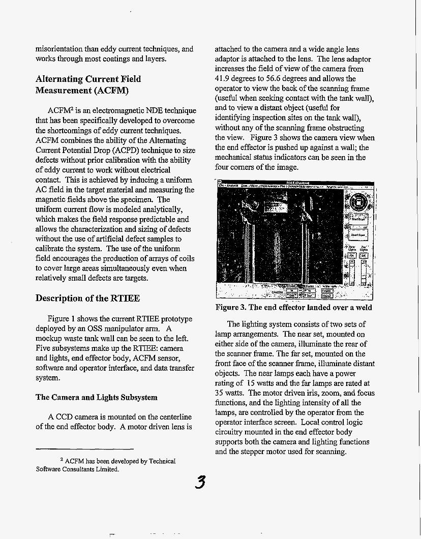
attached to the camera and a wide angle lens adaptor is attached to the lens. The lens adaptor increases the field of view of the camera from 41.9 degrees to 56.6 degrees and allows the operator to view the back of the scanning frame (usefbl when seeking contact with the tank wall), and to view a distant object (useful for identifying inspection sites on the tank wall), without any of the scanning frame obstructing the view. Figure 3 shows the camera view when the end effector is pushed up against a wall; the mechanical status indicators can be seen in the four corners of the image.
The lighting system consists of two sets of lamp arrangements. The near set, mounted on either side of the camera, illuminate the rear of the scanner frame. The far set, mounted on the front face of the scanner h e , illuminate distant objects. The near lamps each have a power rating of 15 watts and the far lamps are rated at 35 watts. The motor driven iris, zoom, and focus functions, and the lighting intensity of all the lamps, are controlled by the operator from the operator interface screen. Local control logic circuitry mounted in the end effector body supports both the camera and lighting functions and the stepper motor used for scanning.
3
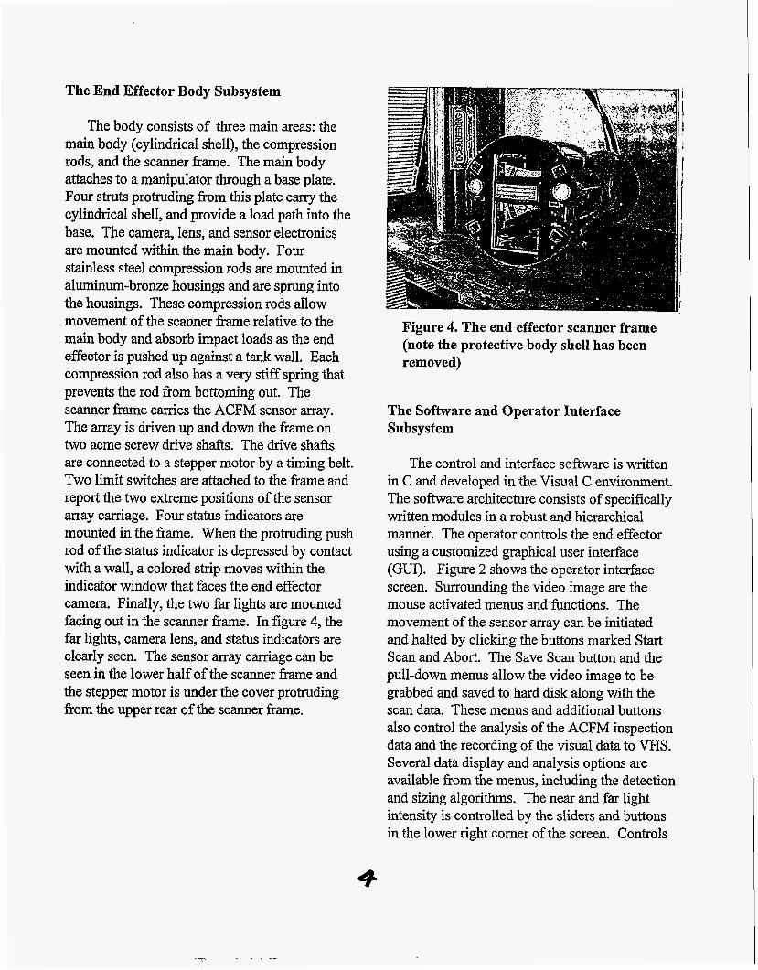
The End Effector Body Subsystem
The body consists of three main areas: the main body (cylindrical shell), the compression rods, and the scanner frame. The main body attaches to a manipulator through a base plate. Four struts protruding from this plate carry the cylindrical shell, and provide a load path into the base. The camera, lens, and sensor electronics are mounted within the main body. Four stainless steel compression rods are mounted in aluminum-bronze housings and are sprung into the housings. These compression rods allow movement of the scanner frame relative to the main body and absorb impact loads as the end effector is pushed up against a tank wall. Each compression rod also has a very stiff spring that prevents the rod from bottoming out. The scanner frame carries the ACFM sensor array. The array is driven up and down the frame on two acme screw drive shafts. The drive shafts are connected to a stepper motor by a timing belt. Two limit switches are attached to the frame and report the two extreme positions of the sensor array carriage. Four status indicators are mounted in the frame. When the protruding push rod of the status indicator is depressed by contact with a wall, a colored strip moves within the indicator window that faces the end effector camera. Finally, the two far lights are mounted facing out in the scanner frame. In figure 4, the far lights, camera lens, and status indicators are clearly seen. The sensor array carriage can be seen in the lower half of the scanner fiame and the stepper motor is under the cover protruding fiom the upper rear of the scanner fi-ame.
Figure 4. The end effector scanner frame (note the protective body shell has been removed)
The Software and Operator Interface Subsystem
The control and interface software is written in C and developed in the Visual C environment. The software architecture consists of specifically written modules in a robust and hierarchical manner. The operator controls the end effector using a customized graphical user interface (GUI). Figure 2 shows the operator interface screen. Surrounding the video image are the mouse activated menus and functions. The movement of the sensor array can be initiated and halted by clicking the buttons marked Start Scan and Abort. The Save Scan button and the pull-down menus allow the video image to be grabbed and saved to hard disk along with the scan data. These menus and additional buttons also control the analysis of the ACFM inspection data and the recording of the visual data to VHS. Several data display and analysis options are available from the menus, including the detection and sizing algorithms. The near and far light intensity is controlled by the sliders and buttons in the lower right corner of the screen. Controls
4
for the camera lens zoom, focus, and iris are arranged below the inspection windows.
The ACFM Sensor Subsystem
The sensor system consists of two main components: the sensor array, and the data acquisition electronics. The sensor array is made up of 96 Bz coils and 32 Bx coils arranged in four rows (each coil has an outside diameter of .070"). Behind each row is a printed circuit board (pcb) populated with multiplexing and signal processing chips and components. Each pcb is connected via a transition pcb to an umbilical. The umbilical connector and all the boards are mounted inside a carbon steel box which is located in the sensor array carriage. The umbilical connects the array to the data acquisition electronics; the data acquisition electronics are connected to the control computer via a serial line.
The ACFM array inspects metal plate by inducing AC fields onto the plate and sensing disturbances in the field with sensor coils that are scanned over the plate. By using a theoretical model of the field and a look-up table, the system can then size any pits it detects. The prototype end effector features two types of solenoids to provide two directions of input field @ and Z) and two orientations of sensor coil (Bx and Bz) to be sensitive to different components of the magnetic field above the plate. The Z field solenoid is wound around the array carriage. The two X field solenoids are mounted on either side of the scanning window.
The variation in the magnetic field caused by pits is very small compared to the general field, so a normalization procedure is used to highlight the pit signal. Experimentation indicates that normalization of the whole scan area is the most effective method. This implies that a complete
scan of the 6" by 3" window, on a known good plate, is stored in the s o h a r e and then subtracted from all scans of similar material. This method has the additional advantage of removing all repeatable field variations caused by the presence of end effector structure around the array. A plate suitable for normalization would be made of the same grade of steel as the tank wall and be approximately the same thickness, it would also be of a large enough area to prevent the plate edges disturbing the field produced by the end effector (currently this is about 14"x14").
The Data Transfer Subsystem
Power and data is transferred to and from the end effector through a single umbilical. This umbilical terminates at a 37 pin connector at the rear of the end effector. The umbilical is 50' long to simulate transmission of power and data over a representative length. Sensor may data is collected by the data acquisition unit and passed to the interpretation s o h a r e in the computer via the serial line. Provision has been made in the prototype system to drive all supply and signal voltages through 250' of cable if required.
Test Results
The current RTIEE prototype is designed to detect and size corrosion pitting in carbon and stainless steels. Other defects such as cracks and other linear features at welds (lack of penetration, lack of fusion, etc.) will be detectable by the new system currently under development.
As discussed previously, ACFM relies on the imposition of a uniform current field onto the surface of the material to be inspected. This allows the disturbance of the field, caused by a defect, to be modeled analytically; this is strictly true only on materials with a small skin depth.
5
The smaller the pit that can be confidently characterized, the greater the accuracy of the assessment of corrosion damage on the inner tank wall. There are two aspects to this capability: the fmt is the ability of the operator or computer to detect the presence of a defect in the magnetic field; the second is the accuracy of the algorithm that sizes the defect based on the amplitude and position of the disturbances in the various fields. The RTIEE design incorporates automatic detection and location algorithms to reduce the level of expertise required by an operator, and to provide the operator with a real time graphical depiction of the condition of the tank wall.
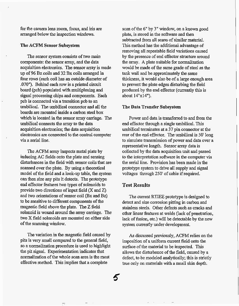
Figure 5 shows the disturbance of the uniform X field as it flows around and into a pit. These experimental results, for carbon steel,
50 25 0
response consisting of a peak centered over the defect. The RTIEE detection and sizing algorithms use different combinations of field and sensor data depending on the material being inspected. When working on carbon steel, for instance, the ZBz data is first examined for peaks. Having detected a peak, the X fieldsensor combinations are examined in the same area to locate their dominant features. If the right features are located then confidence in the presence of a defect increases and the amplitude and position of the dominant features are used to size the defect. The relationship between the disturbance of a field and the diameter and depth of the pit is determined by running the theoretical model for all combinations of pit diameter-to-depth and creating a look up table of results. The model therefore greatly reduces the cost of developing
1 ' Figure 5. Magnetic fields recorded above a pit in the presence of a uniform field, XBz (left) and XBx (right)
closely match the response predicted by the analytical model, and illustrate the pealcltrough pair seen by a Bz sensor and the tipped depression seen by the Bx sensor. The ZBz disturbance is not modeled but is such a strong response that the RTIEE uses it to detect pits. The ZBz disturbance is the classic eddy current
an inspection tool by reducing the number of test plates required to calibrate the system.
This robust approach to defect detection and sizing is only limited by the practicalities of field deployment. Essentially, small pits produce small field disturbances which decay close to the
6

surface of the steel. Therefore if small defects are to be detected, the sensor head must scan, as a general rule, not more than one pit diameter away fiom the material surface. The type of steel in the tank wall can also effect results. Stainless steel represents a slightly different challenge than carbon steel because at the inspection field frequency used by the RTIEE (Smz) the material has a significant skin depth (about .22" as opposed to .005" in carbon steel). This skin depth has the advantage of allowing the RTIEE to detect subsurface features. Results for the inspection of carbon steel by the RTIEE are reported in Hughes and Gittleman, 1995. A more thorough discussion of detecting and sizing corrosion pits in stainless and carbon steel can be found in the project's draft final report. The following summarizes the results for the inspection of stainless steel.
Inspection of Stainless Steel
Inspection of stainless steel uses the XBx and XBz fields to detect and size defects. Figure 6 illustrates the screens the operator sees following an inspection of a grid of pits with the
. , ,' .
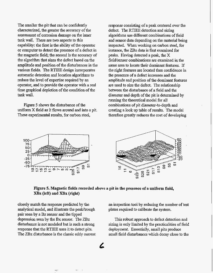
XBx and XBz fields illustrated. The depressions in the XBx field, over the larger pits, are clearly seen. This image can be compared to the XBz field for the same inspection that has peak trough pairs over the pits. Figure 7 illustrates the detection and sizing display. The image consists of the detection and sizing display next to a video image of the inspected area. The location, diameter, and depth of each pit detected is listed in the small window. The pit location is recorded in Cartesian co- ordinates relative to the end-effector coordinate system; the upper left comer of the scanning frame corresponds to the origin (0,O). As these images attest, the location algorithm accurately locates the pits, typically within one pit radius of the actual position. Two diameters are shown (horizontal and vertical) to allow the representation of oval features, and the depth measurement is followed by a confidence level that is based on the number of field/sensor combinations that sense the defect. If the detection threshold is set low enough to find even the shallowest .030" pits some spurious indications occur. If the threshold is set slightly higher, only genuine pits are detected and sized.
Figure 6. RTIEE results showing the magnetic fields over a grid of pits, X B x (left) and XBz (right)
7
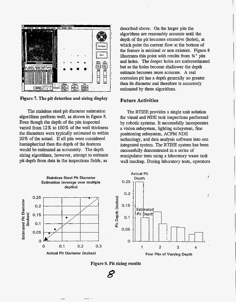
Figure 7. The pit detection and sizing display
The stainless steel pit diameter estimation algorithms perform well, as shown in figure 8. Even though the depth of the pits inspected varied from 12% to 100% of the wall thickness the diameters were typically estimated to within 20% of the actual. If all pits were considered hemispherical then the depth of the features would be estimated as accurately. The depth sizing algorithms, however, attempt to estimate pit depth from data in the inspections fields, as
Stainless Steel Pit Diameter Estimation (average over multiple
depths)
0.25
0.2
0.1 5
0.1
0.05
0 0 0.1 0.2 0.3
Actual Pit Diameter (inches)
described above. On the larger pits the algorithms are reasonably accurate until the depth of the pit becomes excessive (holes), at which point the current flow at the bottom of the feature is minimal or non existent. Figure 8 illustrates this point with results from % 'I pits and holes. The deeper holes are underestimated but as the holes become shallower the depth estimate becomes more accurate. A real corrosion pit has a depth generally no greater than its diameter and therefore is accurately estimated by these algorithms.
Future Activities
The RTIEE provides a single unit solution for visual and NDE tank inspections performed by robotic systems. It successfully incorporates a vision subsystem, lighting subsystem, fine positioning subsystem, ACFM NDE technology, and data analysis software into one integrated system. The RTIEE system has been successfully demonstrated in a series of manipulator tests using a laboratory waste tank wall mockup. During laboratory tests, operators
Actual Pit
rn 0-25 0.2 i7 a .c
0.15 .- - 5 a 0.1 n n
P
+I .- 0.05
0
1 2 3 Four Pits of Varying Depth
4
Figure 8. Pit sizing results

used the RTIEE to visually identify an area of potential corrosion attack, and then perform detailed and quantifiable electro-magnetic inspections of that area with the compliant scanner frame in contact with the tank wall. The ACFM sensor and defect characterization software has proved capable of detecting and sizing pits on stainless and carbon steels to a minimum diameter of .030".
Acknowledgments
This work is sponsored by the DOES Morgantown Energy Technology Center, and is conducted under the Environmental Management's High-Level Waste Tank Remediation Focus Area. Oceaneering Space Systems would like to thank Cliff Carpenter of the METC for his technical management of this effort and Allan Pardini of the Westinghouse Hanford Company for his technical assistance.
The new prototype, under development at OSS, will increase the capability of the RTIEE to include inspection for cracks. In addition, the incorporation of a fly-by inspection mode will greatly increase the area of tank wall that can be inspected in a given time, and this in turn will increase the cost-effectiveness of the end effector system.
References
Hughes,G., andM.M. Gittleman. 1995. A Robotic End Effector for Visual and Electromagnetic Inspection of Waste Storage Tank Walls. In Proceedings of the ANS 6th Topical Meeting on Robotics and Remote Systems, 347-354. American Nuclear Society, Inc. La Grange Park, IL.