a segmentation technique for flexible pipes in deep ... pipes segmentation in underwater...
TRANSCRIPT

PESSOA ET AL.: FLEXIBLE PIPES SEGMENTATION IN UNDERWATER ENVIRONMENTS 1
A Segmentation Technique for FlexiblePipes in Deep Underwater Environments
Saulo Pessoa1
Vinicius Cesar1
Bernardo Reis1
Judith Kelner1
Ismael Santos2
1 Informatics CenterFederal University of PernambucoRecife, Brazil
2 CENPESPetrobras,Rio de Janeiro, Brazil
Abstract
This paper presents a segmentation technique for flexible pipes in deep underwaterenvironments using low-light monochrome cameras. The technique relies on an alter-nating pattern of black and white regions marked over the pipe and is divided into threestages: a pre-processing stage for image noise-reduction; a multi-level topological bi-narization for collecting pipe region candidates; and a backtracking search constrainedby inherent pipe characteristics for segmenting its regions. The proposed technique hasbeen tested using video sequences from a real offshore operation and succeeded in seg-menting 95.29% of the frames, while local adaptive thresholding methods achieved, atbest, a rate of 68.49%.
1 IntroductionOil and gas are some of the most important energy sources in the modern world. These re-sources can be produced in either continental or offshore fields. The offshore oil production,in particular, involves additional challenges since it requires a further effort to reach the ex-traction point — the seabed. The offshore oil extraction is a complex operation that requiresspecialized professionals and expensive equipment. The risks involved are high and minormistakes may result in incalculable losses.
Offshore operations are usually conducted in deep underwater environments (at timessurpassing 1000 m in depth). Consequently, ROVs (Remotely Operated Vehicles) assist mostparts of the operations [20]. There is no natural illumination in this kind of environment andthe only light sources available are the ones attached to the ROV. Since illumination is scarce,ROVs are equipped with special underwater camera systems, which can capture images inlow-light conditions (10−3 lux). These images are monochromatic, low resolution (usuallyNTSC or PAL standards), and tend to be blurred due to the underwater light scattering.
c© 2015. The copyright of this document resides with its authors.It may be distributed unchanged freely in print or electronic forms. Pages 135.1-135.12
DOI: https://dx.doi.org/10.5244/C.29.135

2 PESSOA ET AL.: FLEXIBLE PIPES SEGMENTATION IN UNDERWATER ENVIRONMENTS
~𝑎 ~𝑎 ~𝑎
𝑎 ⋯ ⋯
~𝑎/2
Figure 1: Alternating black and white pattern used to mark the pipe. White marks must havea length of about a and the black ones of about a/2. The first and last marks must be blackand have a length of about a (as it delimits the region of interest).
Special flexible pipes are used to transport oil and gas. They are affected by permanentoscillation caused by ocean currents, and, if the oscillation reaches a critical amplitude, thepipes may fracture [9]. In order to mitigate the risks involved in such situations, computervision systems might be used as underwater monitoring tools.
This paper presents a novel segmentation technique for flexible pipes in deep underwaterenvironments. It is the initial step towards the development of a monitoring tool based on 3Dreconstruction. Since the pipe is a non-rigid object, a calibrated stereo rig is to be used, whichrequires that feature points are extracted and matched across both images. The segmentationproblem is addressed by finding regions of the pipe denominated vertebrae. For improvingthe technique robustness, considering the low quality of the available images, it relies onan alternating pattern of white (a vertebra) and black regions marked on the pipe. Resultsshow that the proposed technique can segment pipes even under harsh conditions such as:low contrast between pipe and background; uneven illumination of the pipe; and high levelof noise due to floating particles. In particular, the proposed binarization technique achievesvaluable results without any parameter, whereas state-of-the-art techniques did not achievethe same quality even after their parameters were fine-tuned for each condition.
2 Related Work
In the literature of computer vision and pattern recognition, underwater pipe detection andtracking techniques have been widely investigated for surveillance, inspection, and main-tenance tasks. Such techniques are commonly applied to guide AUVs (Autonomous Un-derwater Vehicle), and utilize sonars and optical devices. Whereas sonars are powerful forsearching large areas, but expensive and susceptible to noise; optical devices face problemslike uneven illumination and unwanted artifacts on images [7].
For optical-based techniques, the most common approach involves detecting the pipeboundaries in a scenario where the optical axis of the camera is parallel to the pipe. Pipeboundaries are detected by extracting all edges from image and selecting pairs of parallellines [1, 11, 12, 22]. The boundaries are approximated by straight lines because the pipe hassmall curvature, such as in [5], where two multilayer perceptrons are used to detect them.To track the movement over time, the pipe is redetected in the next frame and its position iscomposed with the position in the previous frames using Kalman filter. In [18], a machinelearning technique for pipe detection in factories is proposed, employing user interactionand segmenting the pipe by characteristics like boundaries, color, and shades. Althoughthe presented works are able to segment pipes from images, they would not succeed in thescenario of this paper owing to the flexibility of the pipe.
Concerning the proposed binarization algorithm, there are global and local threshold-

PESSOA ET AL.: FLEXIBLE PIPES SEGMENTATION IN UNDERWATER ENVIRONMENTS 3
ing techniques, both of which achieve analogous results. The global ones may evaluate thethreshold value in many ways, such as using histograms, entropy, mean, and variance [16].Otsu’s algorithm [13] chooses a threshold that maximizes the variance between the fore-ground and background. However, global approaches are not robust to uneven illumination.Locally adaptive thresholding techniques classify pixels by examining their neighborhood,established by a window size given as parameter. Bradley [3] uses the mean of the neighbor-hood to classify each pixel, while Sauvola [15] uses the mean and the variance. Bernsen [2]defines the threshold as the mean of the minimum and maximum intensity of the window.All of these techniques are very sensitive to their input parameters, and a slight variation inthem may cause any of the following issues: (i) connection between segmented regions; (ii)noise in the regions surrounding the pipe; (iii) or holes inside the segmented regions. Theproposed binarization technique does not produce such undesirable artifacts and does notrequire an strenuous job to parameterize it.
Finally, it is worth mentioning the techniques for detecting and segmenting vertebralcolumn in X-ray [21], CT (Computed Tomography) [6, 8], and MR (Magnetic Resonance)imaging [10, 14]. Despite these techniques are also interested in segmenting a sequenceof structured elements, there are several aspects that makes their objectives unlike the onetargeted by this paper. Firstly, most of them are intended to scenarios with relaxed time re-strictions. The usual running-time per image reported by them are of minutes or even tensof minutes. Secondly, they usually rely on typical characteristics of the human vertebral col-umn (such as the sacrum, the intervertebral disks, and the articulation to ribs of the thoracicvertebrae), which are not present in the underwater scenario. Lastly, user intervention arerequired in some stages (such as for initializing and training).
3 ScenarioThe purpose of the developed segmentation technique is to provide feature points that will beposteriorly matched across a pair of stereo images. However, since flexible pipes are oftencoated with plastic of uniform color, it is almost impossible to distinguish feature pointsalong its length. In order to overcome this, the pipe is marked with an alternating black andwhite pattern (Figure 1). This can be easily achieved by using colored adhesive tapes or bypainting the pipe surface. Since the region of the pipe that shall be monitored is short (about15 m, which results in 29 markings for a 35 cm diameter pipe), this manual task is affordable.
The proposed technique searches for the pipe’s vertebrae (the white markings). In orderto be visible, there must be a minimum contrast between the vertebrae and the background,which leads to the final requirement: the image background must be darker than the verte-brae. This is naturally fulfilled since the environment is poorly illuminated.
4 Proposed TechniqueThe technique consists of three stages. Firstly, the input image is pre-processed to reducenoise. Secondly, the pre-processed image is binarized by the proposed Multi-level Topo-logical Binarization technique, resulting in a binary image which highlights, in white, everyregion that is potentially a pipe vertebra (those regions are henceforth referred to as blobs).Lastly, the pipe is segmented by finding the best sequence of blobs that fulfill a set of restric-tions inherent to a marked pipe.

4 PESSOA ET AL.: FLEXIBLE PIPES SEGMENTATION IN UNDERWATER ENVIRONMENTS
60
X
4020
00
20Y
40
0
50
100
150
250
200
Inte
nsity
(a) (b) (c) (d)Figure 2: Input image (a) after applying a bilateral (b) and a Gaussian filter (c). Second rowexhibits the images in details. The bilateral filter parameters are kernel size 30, sigma color10, and sigma spatial 10. The Gaussian filter parameters are kernel size 13 and sigma 2.7. In(d), the plot of the detailed image in (c) exhibiting the peaks produced by the pipe marks.
4.1 Pre-processing
Since the images captured by the ROV cameras are subject to a great amount of noise (Figure2a), two blurring filters are used before their binarization. First, a bilateral filter [19] is usedto remove small particles floating around, while preserving the vertebrae’s edges (Figure 2b).Finally, a Gaussian filter is used to uniformly smooth the images (Figure 2c).
4.2 Multi-level Topological Binarization
The proposed binarization technique was conceived to be robust to uneven illumination. Thisfeature is important because the ROV’s lamps cannot evenly illuminate the scene. Anotherinteresting feature of the technique is that it tends to generate disconnected vertebrae — evenclose vertebrae separated by a shallow valley will end up disconnected. It is an importantfeature because the searching stage relies on it. Besides, this is something that the usualbinarization techniques do not achieve.
The basic idea behind the technique consists in finding peaks in the pre-processed image.Observe that whenever a pipe vertebra appears in the image it will produce a peak (Figure2d). So, one can assume that, by collecting every peak from the pre-processed image, everyvertebra will necessarily be collected. It is evident that some peaks will arise from the par-ticles floating around, but the most important thing in this moment is to avoid false negativeerrors, as false positives errors will be handled later.
In order to formally define a peak, some basic elements need to be defined. A 2D imageis denoted by the function f (x,y) : R2 → R, such that f (x,y) ≥ 0 (since pixels intensityare non-negative values). The region that is under the graph of this function is denotedby the set of points S = {(x,y,z) ∈ R3|0 ≤ z ≤ f (x,y)}. Also, let a parallel plane to thexy-plane be pb = {(x,y,z) ∈ R3|z = b}, where b is its level. Since the image function isstrictly non-negative, only planes such that b ≥ 0 are considered. These planes slice theregion S by applying a slicing operation denoted by C(pb) = S∩ pb. The points generatedby the slicing operation can be grouped into subsets of connected components si,b, such thatC(pb) =
⋃ni=1 si,b. Each slicing operation produces n≥ 0 connected components, which are
also called slices. Therefore, one may say that si,b is the i-th slice produced by plane pb. Byconsidering the previous definitions, one may also say that C(p0) = s1,0 = p0, i.e., the lowest

PESSOA ET AL.: FLEXIBLE PIPES SEGMENTATION IN UNDERWATER ENVIRONMENTS 5
𝑠1,0
𝑠2,1
𝑠2,2
𝑠2,3
𝑠1,4
𝑠1,1
𝑠3,2
𝑠3,3
𝑠2,1 𝑠2,2
𝑠1,3
𝑠1,4
𝑠1,2
𝑠3,3
𝑠1,1
𝑠1,0
𝑠1,2
𝑠1,3
𝑠2,3
𝑠3,2
genus-0
genus-1
genus-2
(a) (b)Figure 3: In (a), the surface plot of an image and the respective tree of slices. In (b), topo-logical classification of slices obtained from different surface plots.
plane produces only a single slice that is equivalent to this plane. Finally, let the projectionof slice si,b be s′i,b = {(x,y) ∈ R2|(x,y,z) ∈ si,b}
The presented slicing process has an interesting characteristic: for any s′i,b with b > 0,there is only one s′j,b−1 such that s′i,b ⊆ s′j,b−1. In Figure 3a, for example, s′1,1 and s′2,1 aresubsets of s′1,0; s′1,2 is subset of s′1,1; s′1,3 is a subset of s′1,2; and so on. Since this relationshipcan always be established between slices produced by consecutive planes, one can constructa tree of slices representing this hierarchy. The root of this tree is always the slice producedby p0, i.e., slice s1,0.
An important notion about slices are their topology. In simple terms, slices are topo-logically classified according to the number of holes they have; the number of holes definewhat is hereby denominated as the genus of a slice. Slices without holes have genus-0, sliceswith only one hole have genus-1, slices with two holes have genus-2, and so on. For ex-ample, Figure 3b exhibits how slices obtained from different surface plots are topologicallyclassified.
Intuitively speaking, peaks are prominences similar to the first one exhibited in Figure3b. One can notice it by observing surface plots of real pipe images (after the pre-processingstage). Peaks can be envisioned as mountains that do not retain rainwater (every drop tricklesdown to the mountain base). There are two factors that favor this characteristic: pipe verte-brae are solid white regions with a dark vicinity, and the Gaussian filter of the pre-processingstage softens hard edges of vertebrae and hides eventual flaws in pipe marks. More formally,a peak is a sequence of nodes denoted by P = {nk}m
k=1 = n1,n2, . . . ,nm, such that:
• nm is a leaf node of the tree;
• nk, such that 1≤ k < m, is the parent node of nk+1;
• n1 is the only element that has a brother node, or n1 is the only element that has aparent with genus greater than zero, or n1 is the root node.
Nodes n1 and nm are respectively named the base and the top of a peak.Given a tree of slices, one has to traverse it from leaves to root in order to find its peaks.
For each node visited, three conditions must be checked: whether it has a brother; whether itsparent has genus greater than zero; and whether it is the root node. If any of these conditionsis satisfied, the sequence from the current node until the leaf is considered a new peak andtraversal is restarted selecting another leaf node; otherwise, the current node’s parent is setas the new current node and the traversal goes on. At the end of this process, every peak will

6 PESSOA ET AL.: FLEXIBLE PIPES SEGMENTATION IN UNDERWATER ENVIRONMENTS
⋯ ⋯
𝑚160 𝑚80
⋯ ⋯
𝑚120
(a) (b) (c)Figure 4: Slicing images (b) generated by repeatedly applying a simple thresholding opera-tion in the pre-processed image (a). In (c), the result of the proposed binarization technique.
be found. For example, Figure 3a contains three peaks which can be found by traversingits tree of slices. The first peak is P′ = s1,2,s1,3 (traversal stopped in s1,2 because its parenthas genus-1). The second peak is P′′ = s2,2,s2,3 (traversal stopped in s2,2 because it hasa brother). And finally, the third peak is P′′′ = s3,2,s3,3,s1,4 (traversal stopped in s3,2 alsobecause it has a brother). The technique was named multi-level topological binarizationbecause it analyzes slices from multiple levels and their topology is taken into account.
A practical way of implementing the proposed thresholding technique is to perform thefollowing steps: slice the pre-processed image by using a simple thresholding operation atevery possible level; evaluate boundaries of the produced slices; construct the tree of slices;traverse the tree in order to find peaks; and, finally, create the final thresholded image bydrawing nodes which are the base of the peaks.
A simple thresholding operation evaluates pixels of the pre-processed image producingbinary images mb such that pixels greater than or equal to a threshold value b are white;otherwise, they are black. One binary image is generated for each possible threshold b (256for the usual grayscale images). Since the connected white regions contained in a binaryimage can be understood as slices, this image is named slicing image (Figure 4b).
Subsequently, one has to find the boundaries of the slices of each slicing image. Noticethat internal boundaries (when they exist) are also required to find out the genus of the slices.
The tree of slices is constructed by analyzing the boundaries found in the previous step.This analysis starts from the lowest slicing image m0 to the highest m255. The slicing imagem0 always has only one slice, so it becomes the root of the tree. For the next images, onehas to find the parental relationship between slices from consecutive slicing images. For anyslice si,b, only one s j,b−1 exists such that si,b ∩ s j,b−1 = si,b. Thus, in order to verify if si,bis a child of s j,b−1, one may simply test whether one pixel of si,b is inside s j,b−1 (which ischeaper than testing the whole slice).
The traversal of the tree data structure from leaves to root is achieved by a usual recursivetraversal, but the tests that identify if a slice is the base of a peak are performed after therecursion call return.
The final step consists in drawing the base of the separated peaks in white into a blackbackground. This image is the final thresholded image (Figure 4c). The white regions drawninto this image are called blobs, which are potential pipe vertebrae.
The reference implementation used mostly OpenCV [4] functions to perform these tasks.
4.3 Object SegmentationThe previous stage results in a set of blobs B = {bi : i ∈ {1, . . . ,n}}. However, some ofthe blobs found are not related to the pipe. The blobs originating from the pipe vertebrae areselected by searching for the longest chain of blobs that respects restrictions that are inherent
PESSOA ET AL.: FLEXIBLE PIPES SEGMENTATION IN UNDERWATER ENVIRONMENTS 7
to a pipe marked such as in Figure 1. This chain is denoted by a sequence V = { jk}mk=1 =
j1, j2, . . . , jm, where jk is the index of a blob bi. This sequence has a LIFO policy.A backtracking algorithm finds the sequence V . It starts by iterating over all blobs of
B. For each blob visited, its index is inserted into V (for the sake of simplicity, henceforthone may say that a blob, instead of its index, is inserted into V ) and the algorithm searchesrecursively for a blob that satisfies some restrictions (see below). When a blob is found, itis inserted into V and a new blob is sought. When blobs can no longer be inserted into V(i.e., they do not respect the restrictions), the current V is stored (if it is the longest sequencefound so far) and the algorithm backtracks (i.e., it steps back by removing the last elementof V ). After backtracking, the search for a new blob continues from where it had stopped.This process is repeated until all blobs are examined.
The restrictions explained below rely on the physical characteristics of the pipe and onthe regularity of the marks painted over it. The following definitions will also be used: bi isthe current blob being tested to be inserted into V ; bl is the last blob inserted into V ; and bpis the blob inserted immediately before bl (i.e., l = jk and p = jk−1). The distance functionused d : R2×R2→ R evaluates the Euclidian distance between two points.
The first restriction limits the distance between the centroids of bi and bl , respectively ciand cl . So, in order to insert bi into V , the following restriction must satisfy:
d(ci,cl)≤ dmax, (1)
where dmax is the maximum acceptable distance. One can estimate dmax by regarding: thedistance between two consecutive vertebrae 3a
2 (Figure 1); the closest distance the ROV issupposed to be from the pipe drov
1; and the focal length of the camera in pixels f . Thus,dmax =
fdrov
3a2 .
The second restriction limits the length of the gap between bi and bl . This gap is denotedby the line segment oiol , where oi is the closest intersection point between the line segmentcicl and the contour of bi. The intersection point ol is similarly defined. Hence, in order toinsert bi into V , the following restriction must satisfy:
d(oi,ol)≤ gmax, (2)
where gmax is the maximum acceptable gap length. Since gaps appear because of the blackmarks over the pipe, one may define gmax = d(ci,cl)/3.
The third restriction limits the distance d(oi,ci), which can be understood as a radius ofbi. This distance has an upper and lower limit. So, in order to insert bi into V , the followingrestrictions must satisfy:(
11+ vmax
)×d(ol ,cl)≤ d(oi,ci)≤ (1+ vmax)×d(ol ,cl), (3)
where vmax ≥ 0 is a user parameter that represents the acceptable radius variation.The last restriction limits the exterior angle between cpcl and clci, which is denoted by
θi. Since three points are required to form an angle, this restriction only applies when thereare at least two blobs already inserted into V . Consequently, in order to insert bi into V , thefollowing restriction must also satisfy:
θi ≤ θmax, (4)
where θmax is a user parameter defined by consulting the technical specifications of the pipe.1This distance is estimated through data acquired from a sonar when the pipe is as close as possible and yet
entirely framed in the images.
8 PESSOA ET AL.: FLEXIBLE PIPES SEGMENTATION IN UNDERWATER ENVIRONMENTS
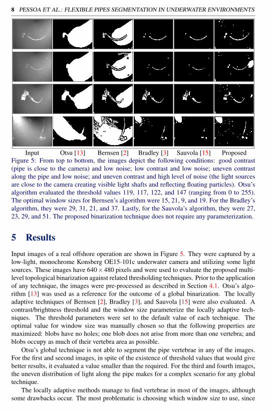
Input Otsu [13] Bernsen [2] Bradley [3] Sauvola [15] ProposedFigure 5: From top to bottom, the images depict the following conditions: good contrast(pipe is close to the camera) and low noise; low contrast and low noise; uneven contrastalong the pipe and low noise; and uneven contrast and high level of noise (the light sourcesare close to the camera creating visible light shafts and reflecting floating particles). Otsu’salgorithm evaluated the threshold values 119, 117, 122, and 147 (ranging from 0 to 255).The optimal window sizes for Bernsen’s algorithm were 15, 21, 9, and 19. For the Bradley’salgorithm, they were 29, 31, 21, and 37. Lastly, for the Sauvola’s algorithm, they were 27,23, 29, and 51. The proposed binarization technique does not require any parameterization.
5 ResultsInput images of a real offshore operation are shown in Figure 5. They were captured by alow-light, monochrome Konsberg OE15-101c underwater camera and utilizing some lightsources. These images have 640×480 pixels and were used to evaluate the proposed multi-level topological binarization against related thresholding techniques. Prior to the applicationof any technique, the images were pre-processed as described in Section 4.1. Otsu’s algo-rithm [13] was used as a reference for the outcome of a global binarization. The locallyadaptive techniques of Bernsen [2], Bradley [3], and Sauvola [15] were also evaluated. Acontrast/brightness threshold and the window size parameterize the locally adaptive tech-niques. The threshold parameters were set to the default value of each technique. Theoptimal value for window size was manually chosen so that the following properties aremaximized: blobs have no holes; one blob does not arise from more than one vertebra; andblobs occupy as much of their vertebra area as possible.
Otsu’s global technique is not able to segment the pipe vertebrae in any of the images.For the first and second images, in spite of the existence of threshold values that would givebetter results, it evaluated a value smaller than the required. For the third and fourth images,the uneven distribution of light along the pipe makes for a complex scenario for any globaltechnique.
The locally adaptive methods manage to find vertebrae in most of the images, althoughsome drawbacks occur. The most problematic is choosing which window size to use, since

PESSOA ET AL.: FLEXIBLE PIPES SEGMENTATION IN UNDERWATER ENVIRONMENTS 9
0%
20%
40%
60%
80%
100%
0 1 2 3 4 5 6 7 8 9 10 11 12 13 14 15 16 17 18 19 20 21
Per
cen
tage
of
fram
es
Number of vertebrae
Bradley Bernsen Sauvola Proposed
(a) (b)Figure 6: In (a), the proposed technique achieved the highest segmentation rate for 16 verte-brae. In (b), a situation where the proposed algorithm failed to segment the whole pipe.
small windows result in holes inside the blobs and large windows fail to separate the verte-brae. The proposed binarization technique does not require such parameterization, and yetsuccessfully segments every vertebra in the first three images. In the last image, the mostchallenging one, the proposed binarization technique managed to segment seven vertebrae,while the other techniques located five at best. Regarding the amount of outliers, Bradley’sand Sauvola’s algorithms performed the best. However, this is not a big concern in this stage,where the most important feature is to be robust under harsh conditions.
Additionally, a sequence of images was acquired to evaluate the performance over time.The sequence features 5627 frames with good contrast. Even though the pipe is not in a fixedposition, its vertebrae remain framed by the camera. There is a low amount of noise in the se-quence, mainly particles and tiny fish. The criterion chosen to evaluate the segmentation rateis the amount of frames in which at least 16 vertebrae are segmented . The proposed tech-nique segmented the pipe in 95.29% of the frames, whereas Bradley’s algorithm achieved68.49%, Bernsen’s algorithm 13.60%, and Sauvola’s algorithm 5.62%. Figure 6a shows thepercentage of frames as a function of the number of vertebrae segmented. Posterior anal-ysis of the frames in which the proposed technique failed to segment at least 10 vertebraerevealed that there were fish occluding the pipe (Figure 6b). All these tests utilized the fol-lowing restriction parameters for the backtracking algorithm: dmax = 100 pixels; vmax = 1.0;and θmax = 25◦.
Regarding the object segmentation stage, there was a concern that the proposed algorithmmight be too greedy, since the backtracking approach always visits every possible candidatewhile trying to extend the sequence of vertebrae (see pseudo code in Algorithm 1). However,for a set of blobs B and a sequence of vertebrae V , the average case is only O(|B|2+ |B||V |2),since, for every non-vertebra blob, the search is very likely to promptly stop at the secondlevel of recursion. The worst case is O(|B3|), and occurs when all blobs are due to vertebrae(for example, while processing an image without any noise). Despite that, it is important tohighlight that the average amount of blobs is low (36.97 for the previous sequence of im-ages) and that the object segmentation stage is the quickest stage of the proposed technique.Executing it on a desktop with a Core i7-3960X CPU, 24 GB of RAM, a GeForce GTX560 Ti GPU, and a Windows 7 64-bit operating system, took only 1 ms in average, whilethe pre-processing stage took 64 ms (using the GPU implementation of both filters), and thebinarization stage took 123 ms. The high cost of the binarization stage is due to the OpenCV

10 PESSOA ET AL.: FLEXIBLE PIPES SEGMENTATION IN UNDERWATER ENVIRONMENTS
implementation of Suzuki and Abe’s algorithm for boundary search [17].
Algorithm 1 Pseudo code of the backtracking search algorithm.
Input: B . set of blobsOutput: V . sequence of indexes of the longest chain
of blobs1: markedBlobs; . record of the blobs inserted into V2: tempV ; . temporary V3: for all bi ∈ B do4: markedBlobs[i]⇐ true; . mark the current blob5: tempV.PushBack(i); . insert the index i to the
temporary V6: NEXTBLOB(i);7: tempV.PopBack(i);8: markedBlobs[i]⇐ false;
9: procedure NEXTBLOB(l)10: for all bi ∈ B do11: if markedBlobs[i] == true then continue;12: if d(ci,cl)> dmax then continue; . test distance13: if d(oi,ol)> gmax then continue; . test gap14: if d(oi,ci)> (1+ vmax)×d(ol ,cl) or . test radius
d(oi,ci)<( 1
1+vmax
)×d(ol ,cl) then continue;
15: if tempV.Size == 1 then16: markedBlobs[i] = true;17: tempV.PushBack(i);18: NEXTBLOB(i);19: tempV.PopBack();20: markedBlobs[i] = false;21: else if tempV.Size > 1 then22: if θi > θmax then continue; . test angle23: markedBlobs[i] = true;24: tempV.PushBack(i);25: NEXTBLOB(i);26: if tempV.Size >V.Size then27: V ⇐ tempV ;28: tempV.PopBack();29: markedBlobs[i] = false;
6 Conclusion and Future WorkThis paper presented a novel segmentation technique for flexible pipes in deep underwaterenvironments. Despite the low quality of the input images and the adverse conditions ofthe tested scenarios, it achieved promising results. The proposed technique was tested in acommodity desktop computer achieving interactive rates (∼ 5 fps). Regarding the numberof vertebrae found, the proposed binarization technique outperformed state-of-the-art ones.
For future work, the aim is to verify if the proposed binarization technique can succeedwith text characters of a document image. The hypothesis is that, by relaxing the topologicalrestriction, characters may also be binarized. An improvement of the occlusion robustnessof the technique is also expected. Furthermore, false positives may occur when blobs dueto non-vertebrae objects are close to the pipe ends. Since these blobs tends to be moretemporally unstable than the blobs due to vertebrae, it is expected that by analyzing the sizeand the position of the blobs over the last few frames, one can identify false positives.
Acknowledgements: This research was supported by Petrobras and FINEP (TRACKPETROproject). Saulo Pessoa would like to thank FACEPE for his PhD scholarship, and ViniciusCesar would like to thank CNPq for his master’s scholarship.
References[1] Javier Antich and Alberto Ortiz. Underwater cable tracking by visual feedback. In
Pattern Recognition and Image Analysis, pages 53–61. Springer, 2003.

PESSOA ET AL.: FLEXIBLE PIPES SEGMENTATION IN UNDERWATER ENVIRONMENTS 11
[2] John Bernsen. Dynamic thresholding of grey-level images. In International conferenceon pattern recognition, pages 1251–1255, 1986.
[3] Derek Bradley and Gerhard Roth. Adaptive thresholding using the integral image.Journal of graphics, gpu, and game tools, 12(2):13–21, 2007.
[4] Gary Bradski. The opencv library. Doctor Dobbs Journal, 25(11):120–126, 2000.
[5] Gian Luca Foresti and Stefania Gentili. A vision based system for object detection inunderwater images. International Journal of Pattern Recognition and Artificial Intelli-gence, 14(02):167–188, 2000.
[6] Ben Glocker, Johannes Feulner, Antonio Criminisi, David R Haynor, and EnderKonukoglu. Automatic localization and identification of vertebrae in arbitrary field-of-view ct scans. In Medical Image Computing and Computer-Assisted Intervention–MICCAI 2012, pages 590–598. Springer, 2012.
[7] Jonathan Horgan and Daniel Toal. Review of machine vision applications in unmannedunderwater vehicles. In Control, Automation, Robotics and Vision, 2006. ICARCV’06.9th International Conference on, pages 1–6. IEEE, 2006.
[8] Tobias Klinder, Jörn Ostermann, Matthias Ehm, Astrid Franz, Reinhard Kneser, andCristian Lorenz. Automated model-based vertebra detection, identification, and seg-mentation in ct images. Medical image analysis, 13(3):471–482, 2009.
[9] Henan Li. Flexible pipe stress and fatigue analysis. 2012.
[10] Meelis Lootus, Timor Kadir, and Andrew Zisserman. Vertebrae detection and labellingin lumbar mr images. In Computational methods and clinical applications for spineimaging, pages 219–230. Springer, 2014.
[11] Mehdi Narimani, Soroosh Nazem, and Mehdi Loueipour. Robotics vision-based sys-tem for an underwater pipeline and cable tracker. In OCEANS 2009-EUROPE, pages1–6. IEEE, 2009.
[12] Alberto Ortiz, Miquel Simó, and Gabriel Oliver. A vision system for an underwatercable tracker. Machine vision and applications, 13(3):129–140, 2002.
[13] Nobuyuki Otsu. A threshold selection method from gray-level histograms. Automatica,11(285-296):23–27, 1975.
[14] Zhigang Peng, Jia Zhong, William Wee, and Jing-huei Lee. Automated vertebra detec-tion and segmentation from the whole spine mr images. In Engineering in Medicineand Biology Society, 2005. IEEE-EMBS 2005. 27th Annual International Conferenceof the, pages 2527–2530. IEEE, 2006.
[15] Jaakko Sauvola and Matti Pietikäinen. Adaptive document image binarization. Patternrecognition, 33(2):225–236, 2000.
[16] Mehmet Sezgin et al. Survey over image thresholding techniques and quantitativeperformance evaluation. Journal of Electronic imaging, 13(1):146–168, 2004.

12 PESSOA ET AL.: FLEXIBLE PIPES SEGMENTATION IN UNDERWATER ENVIRONMENTS
[17] Satoshi Suzuki et al. Topological structural analysis of digitized binary images byborder following. Computer Vision, Graphics, and Image Processing, 30(1):32–46,1985.
[18] Bertrand Thirion, Benedicte Bascle, Visvanathan Ramesh, and Nassir Navab. Fusion ofcolor, shading and boundary information for factory pipe segmentation. In ComputerVision and Pattern Recognition, 2000. Proceedings. IEEE Conference on, volume 2,pages 349–356. IEEE, 2000.
[19] Carlo Tomasi and Roberto Manduchi. Bilateral filtering for gray and color images.In Computer Vision, 1998. Sixth International Conference on, pages 839–846. IEEE,1998.
[20] Louis L Whitcomb. Underwater robotics: Out of the research laboratory and into thefield. In Robotics and Automation, 2000. Proceedings. ICRA’00. IEEE InternationalConference on, volume 1, pages 709–716. IEEE, 2000.
[21] Gilberto Zamora, Hamed Sari-Sarraf, and L Rodney Long. Hierarchical segmentationof vertebrae from x-ray images. In Medical Imaging 2003, pages 631–642. Interna-tional Society for Optics and Photonics, 2003.
[22] Tie-dong Zhang, Wen-jing Zeng, Lei Wan, and Zai-bai Qin. Vision-based system ofauv for an underwater pipeline tracker. China Ocean Engineering, 26:547–554, 2012.