a self-powered generator - free-energy-info.com · a self-powered generator a free-energy developer...
TRANSCRIPT

A Self-Powered Generator A free-energy developer who lives in South Africa and who prefers to remain anonymous, has very kindly shared the details of his compact self-powered generator so that you can build one if you choose to do so. The developer has continued developing his device through several versions. An early version of the generator had four coils and a rotor which has five magnets in it. Very soon, the four coils were increased to five with the additional coil having three separate windings. Even if you are not familiar with electronics circuit diagrams, please try to follow along as we run through the circuit diagram and explain how the generator works. This is the basic circuit diagram:
The battery marked “A” powers the circuit. A rotor “C”, containing five magnets is moved so that one of the magnets passes near the coils. The coils set “B” has three separate windings on a single core and the magnet moving past those three coils generates a small current in them. The current in coil number “1” flows through the resistor “R” and into the base of the transistor, causing it to switch on. The power flowing through the transistor coil “2” causes it to become a magnet and that pushes the rotor disc “C” on its way, keeping the rotor spinning. It also induces a current in the winding “3” and that current is rectified by the diodes shown in blue, and passed back to charge battery “A”, replacing most of the current drawn from that battery. When the magnet in rotor “C” passes away from the coils, the transistor switches off, moving its collector voltage very quickly up to the +12 Volt line, starving coil “2” of current. Because of the way that coils work, the coil drags the collector voltage on up and it would reach 200 volts or more if it were not connected through the red diode to all five batteries which are connected in one long chain. The batteries will have a combined voltage of just over 60 volts (which is why a powerful, fast-switching, high-voltage MJE13009 transistor is being used. As the collector voltage passes the voltage of the battery chain the red diode starts conducting, passing the available energy in the coil into the battery chain. That current pulse passes through all five batteries, charging all of them. The result is an output of 40 watts of mains voltage and frequency, two 12-volt batteries maintained fully charged and three additional 12-volt batteries charged up for later use. Loosely speaking, that is the basic generator design. In the prototype, the load for long-term testing was a 12-volt 150-watt inverter powering a 40-watt mains light bulb. That design worked very well. The basic design was then modified by the addition of two additional pick-up coils:

Coils “B”, “D” and “E” are all triggered at the same time by three different magnets. That happens five times per rotation. The electrical energy produced in all three coils is passed to the four blue diodes to produce a DC power supply which is used to charge battery “A” which powers the circuit. That additional input to the drive battery caused by the addition of two more drive coils to the stator, makes the system operate securely as self-powered, maintaining the voltage of battery “A” indefinitely. The only moving part of this system is the rotor which is 110 mm in diameter and is a 25 mm thick acrylic disc mounted on a bearing taken from an old computer hard disc drive. The arrangement looks like this:
The magnets are sets of nine circular ferrite magnets, each 20 mm in diameter and 3 mm thick, making each stack of magnets 27 mm long and 20 mm in diameter. The magnet stacks are positioned so that their North poles face outwards. When the magnets have been installed, the rotor is placed inside a strip of plastic pipe which prevents the magnets escaping when the disc is spun rapidly. The plastic pipe is secured to the rotor using five bolts with countersunk heads. The spools of the stator coils are 80 mm long and the coil flanges are 72 mm in diameter. The centre shaft of each coil is made of a length of plastic pipe with a 20 mm outer diameter and an inner diameter of 16 mm. giving a wall thickness of 2 mm. After being wound, that inner diameter is filled with a series of welding rods with their welding coating removed, and which are then encased in polyester resin although a solid bar of soft iron is a good alternative:

With this coil arrangement, the prototype has run continuously for three weeks, maintaining the drive battery at 12.7 volts all the time. At the end of the three weeks, the system was stopped so that it could be altered and tested with a new configuration. In the configuration shown above, the current flowing from the driving battery into the circuit is 70 milliamps, which at 12.7 volts is an input power of 0.89 watts. The output power is either 40 watts or close to it, which is a COP of 45, not counting the fact that three additional 12V batteries are being charged at the same time. That is a very impressive performance for the circuit. The drive method has been used so often by John Bedini, that the developer decided to try out John’s method of tuning for maximum performance. However, it was eventually found that a Hall-effect semiconductor exactly aligned with a magnet gives much better results. Further development of the circuit continued and the power output then reached 60 watts. This is impressive for such a small device, especially when you consider that there is no practical input. For this next step the number of batteries has been reduced to just one. Here is the circuit:

In this arrangement, coil “B” is also pulsed by the transistor and the output from the coils around the rotor is now directed to the output inverter. The drive battery has been eliminated and a low-power 30V transformer and diode run from the inverter output to replace it. Spinning the rotor generates sufficient charge on the capacitor to get the system running without a battery. The output power has now risen to 60 watts which is a 50% improvement. The additional three 12-volt batteries being charged have been eliminated, and so the circuit runs with just one battery. Continuous power output from a single battery which never needs to be recharged is a very satisfactory situation. The next advance was a circuit arrangement using a Hall-effect sensor and an FET transistor. The Hall-effect sensor is aligned exactly with the magnets. That is, the sensor is positioned between one of the coils and the rotor magnet. There is a 1 mm clearance between the sensor and the rotor and the arrangement is adjustable and looks like this:

With the Hall-effect A3144E sensor, the circuit has a 150 watt continuous output and it uses three 12-volt batteries. The first two batteries are used, one is used to power the circuit and provide a mains output, while the second one is being recharged through three diodes wired in parallel to improve the recharging current flow. The two-pole two-way changeover switch “RL1” swaps the batteries over every few minutes using the circuit shown below. This technique keeps both batteries fully charged. Batteries charge better if they are not driving a load while being charged.
The recharging current also flows through a second set of three diodes wired in parallel, recharging the third 12-volt battery which powers the inverter which supplies the load. The test load was a 100-watt bulb and a 50-watt fan. The Hall-effect sensor drives a C5353 transistor but any fast-switching transistor such as a BC109 or a 2N2222 transistor can be used. You will notice that all of the coils are now being driven by the IRF840 FET. The relay used for the switching is a latching type such as this one:
And it is driven by a low current draw ILC555N timer like this:

The capacitors shown in blue are chosen to operate the actual physical relay which is used in the circuit. They give the relay a brief switching pulse when the 555 timer changes state which is every five minutes or so. The 18K resistors across the capacitors are to bleed off the capacitor charge during the five minutes when the timer is in it alternative state. Typically, a 100 microfarad capacitor works well in giving the latching relay a brief switch-over pulse. However, if you wish to avoid switching between batteries, the circuit can be arranged this way:
Here, the battery which powers the inverter supplying the load is increased in capacity and while the developer used two of his 7 Amp-Hour batteries, you can use a standard 12-volt 12 Amp-Hour battery intended for a mobility scooter. All but one of the coils is used to supply current to the output battery and the one remaining coil, which is part of the three-strand main coil, is used to supply the drive battery directly. The 1N5408 diode is a 100-volt 3-amp component. The diodes which are not shown with a type number against them can be any diode in the 1Nxxxx range of diodes. The coils shown connected to the IRF840 FET transistor are physically positioned around the circumference of the rotor. There are five of these coils as the grey shading indicates that the three coils furthest on the right are the separate strands of the main 3-wire composite coil which was shown in the earlier circuits. While the three-strand twisted wire coil prepared for the Bedini-style switching was used for both drive and output purposes, it was actually no longer necessary to use a coil of that type and an ordinary helically wound coil containing
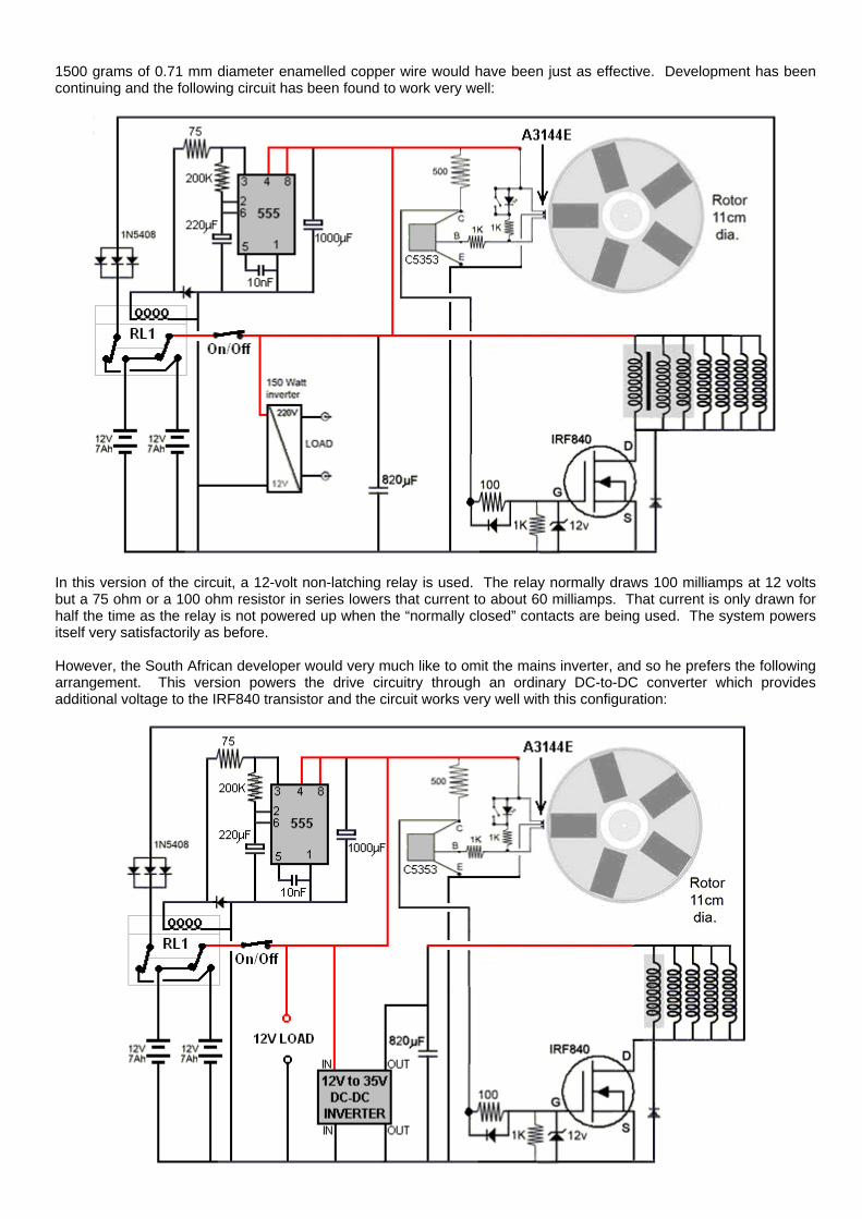
1500 grams of 0.71 mm diameter enamelled copper wire would have been just as effective. Development has been continuing and the following circuit has been found to work very well:
In this version of the circuit, a 12-volt non-latching relay is used. The relay normally draws 100 milliamps at 12 volts but a 75 ohm or a 100 ohm resistor in series lowers that current to about 60 milliamps. That current is only drawn for half the time as the relay is not powered up when the “normally closed” contacts are being used. The system powers itself very satisfactorily as before. However, the South African developer would very much like to omit the mains inverter, and so he prefers the following arrangement. This version powers the drive circuitry through an ordinary DC-to-DC converter which provides additional voltage to the IRF840 transistor and the circuit works very well with this configuration:

The developer stresses that the circuit operates in a non-intuitive way. First, the performance is somewhat reduced if the rotor spins faster which is something which is not at all obvious. Then it has been found that using ferrite magnets produces a better performance than using the stronger neodymium magnets. He sees it as the coil pulses being a mechanism for preventing ‘cogging’ or backward drag on the passing rotor magnets. This is the same thing that Robert Adams found with his high performance motor/generator. In Robert’s design, the rotor was drawn to the iron cores of his coils, making his motor essentially a permanent magnet motor. Admittedly, Robert’s rotor got additional thrusts from the current in his output coils being switched off at exactly the correct instant, but that involved a somewhat higher level of design complexity. While there is no official claim that this South African design is actually a permanent magnet motor/generator, it is difficult not to see some of its performance coming directly from the magnets themselves. Finally, the design which the designer likes best of all is this one which has no inverter or converter and which can power any ordinary 12-volt load:
The output (marked as “12V Load”) is effectively a 12-volt battery which never needs recharging and which can power any typical 12-volt small piece of equipment such as lighting, a fan, a laptop computer or whatever. You will notice that the triple coil is now shown as a single helically wound coil as there is no longer any need for a triple wound coil because the Bedini-style switching is no longer used. Let me stress that the coils driven by the IRF840 FET transistor are shown in a horizontal row just for clarity. In reality, they are spaced out evenly around the rotor, that is, at 72-degree intervals around the rotor. There is nothing special about having five magnets in the rotor and that number could be six, eight, ten or twelve magnets if there is room for the corresponding stator coils around the rotor. It is essential that the rotor itself is made very accurately so that there is no imbalance and so no vibration forces are generated by the rotation. The developer used a lathe to produce a perfect rotor but that option is not generally available to most people. The larger the rotor, the more accurate it needs to be to avoid vibration when it rotates. If you have access to a 3D printer, a good rotor can be printed. One replicator shows his rotor like this:

This one is made in two halves which are then bolted together. The developer has continued advancing his design. One of the things which he didn’t like was the fact that the five coils being used required a total of some 1640 metres of wire, so smaller coils were constructed. This new arrangement works spectacularly well and each new coil has a total wire length of just 22 metres, which is less than one twelfth of the previous wire length. The wire size remains 0.711 mm diameter wire (swg 22 or AWG #21) and each new coil is wound on a 6 mm diameter iron bolt core and the windings cover a length of 24 mm along the bolt which has two 30 mm diameter flanges mounted on it giving an overall length of 30 mm and the completed winding is 27 mm in diameter. There are twelve layers of the 0.71 mm diameter wire on each coil. These new coils are connected in two groups of five in series, giving a DC resistance of about 4 ohms for each chain of five coils. The voltage spikes generated when a set of five coils is switched off is more than 500 volts. The wire in each coil weighs 70 grams. The coils look like this:
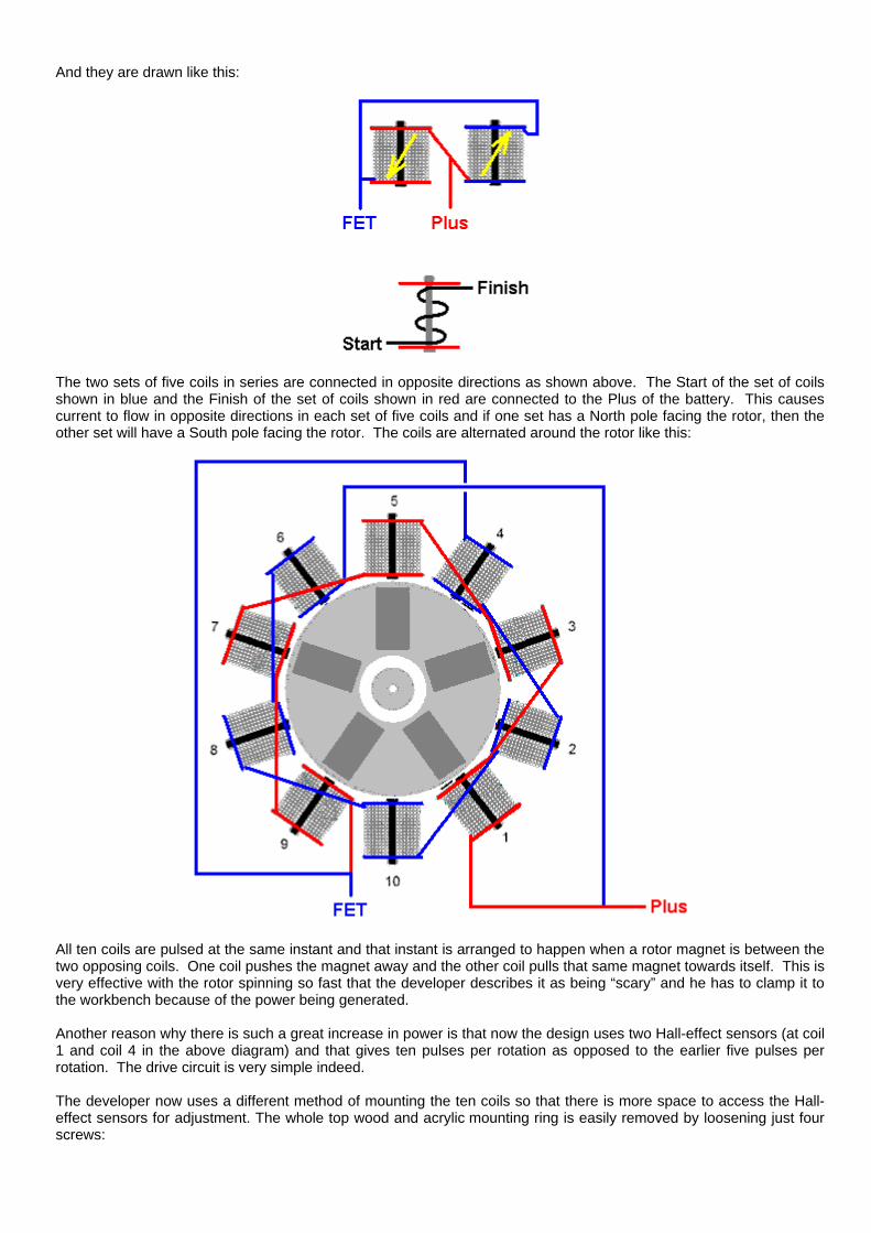
And they are drawn like this:
The two sets of five coils in series are connected in opposite directions as shown above. The Start of the set of coils shown in blue and the Finish of the set of coils shown in red are connected to the Plus of the battery. This causes current to flow in opposite directions in each set of five coils and if one set has a North pole facing the rotor, then the other set will have a South pole facing the rotor. The coils are alternated around the rotor like this:
All ten coils are pulsed at the same instant and that instant is arranged to happen when a rotor magnet is between the two opposing coils. One coil pushes the magnet away and the other coil pulls that same magnet towards itself. This is very effective with the rotor spinning so fast that the developer describes it as being “scary” and he has to clamp it to the workbench because of the power being generated. Another reason why there is such a great increase in power is that now the design uses two Hall-effect sensors (at coil 1 and coil 4 in the above diagram) and that gives ten pulses per rotation as opposed to the earlier five pulses per rotation. The drive circuit is very simple indeed. The developer now uses a different method of mounting the ten coils so that there is more space to access the Hall-effect sensors for adjustment. The whole top wood and acrylic mounting ring is easily removed by loosening just four screws:

The small coils are held in place with cable ties and are easy to remove. Each coil has a resistance of 0.8 ohms and the cores are standard 6 mm diameter galvanised iron bolts which do not retain magnetism, that is, they do not become permanent magnets no matter how often they are stroked repeatedly with a strong permanent magnet. The set of ten coils mounted around the rotor look like this:
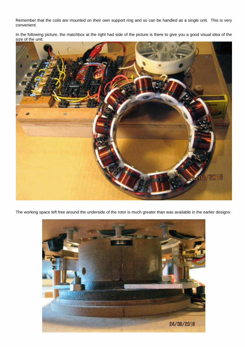
Remember that the coils are mounted on their own support ring and so can be handled as a single unit. This is very convenient. In the following picture, the matchbox at the right had side of the picture is there to give you a good visual idea of the size of the unit:
The working space left free around the underside of the rotor is much greater than was available in the earlier designs:

It is important to understand that while the 110 mm diameter rotor has five magnets located at even intervals around it’s circumference, there are now ten coils on the surrounding stator, and there are now ten pulses per revolution. These pulses are powerful and when the current is cut off, each chain of five coils generates 600 volt spikes (although that can reach 900 volts on occasions). In this latest design, every second coil is wired in reverse so that it presents a South pole to the rotor magnet, and there are now two Hall-effect sensors, one just before the rotor magnet and one just after the rotor magnet. This allows a simplified circuit with just one drive transistor like this:
However, while this circuit works very well, the designer prefers the following circuit arrangement:
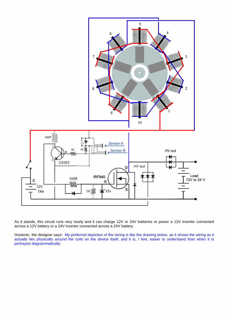
As it stands, this circuit runs very nicely and it can charge 12V or 24V batteries or power a 12V inverter connected across a 12V battery or a 24V inverter connected across a 24V battery. However, the designer says: My preferred depiction of the wiring is like the drawing below, as it shows the wiring as it actually lies physically around the coils on the device itself, and it is, I feel, easier to understand than when it is portrayed diagrammatically:
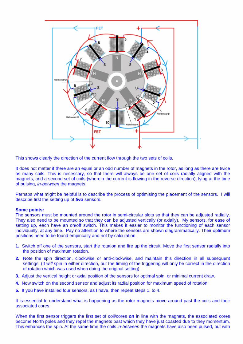
This shows clearly the direction of the current flow through the two sets of coils. It does not matter if there are an equal or an odd number of magnets in the rotor, as long as there are twice as many coils. This is necessary, so that there will always be one set of coils radially aligned with the magnets, and a second set of coils (wherein the current is flowing in the reverse direction), lying at the time of pulsing, in-between the magnets. Perhaps what might be helpful is to describe the process of optimising the placement of the sensors. I will describe first the setting up of two sensors. Some points: The sensors must be mounted around the rotor in semi-circular slots so that they can be adjusted radially. They also need to be mounted so that they can be adjusted vertically (or axially). My sensors, for ease of setting up, each have an on/off switch. This makes it easier to monitor the functioning of each sensor individually, at any time. Pay no attention to where the sensors are shown diagrammatically. Their optimum positions need to be found empirically and not by calculation. 1. Switch off one of the sensors, start the rotation and fire up the circuit. Move the first sensor radially into
the position of maximum rotation. 2. Note the spin direction, clockwise or anti-clockwise, and maintain this direction in all subsequent
settings. (It will spin in either direction, but the timing of the triggering will only be correct in the direction of rotation which was used when doing the original setting).
3. Adjust the vertical height or axial position of the sensors for optimal spin, or minimal current draw. 4. Now switch on the second sensor and adjust its radial position for maximum speed of rotation. 5. If you have installed four sensors, as I have, then repeat steps 1. to 4. It is essential to understand what is happening as the rotor magnets move around past the coils and their associated cores. When the first sensor triggers the first set of coil/cores on in line with the magnets, the associated cores become North poles and they repel the magnets past which they have just coasted due to they momentum. This enhances the spin. At the same time the coils in-between the magnets have also been pulsed, but with
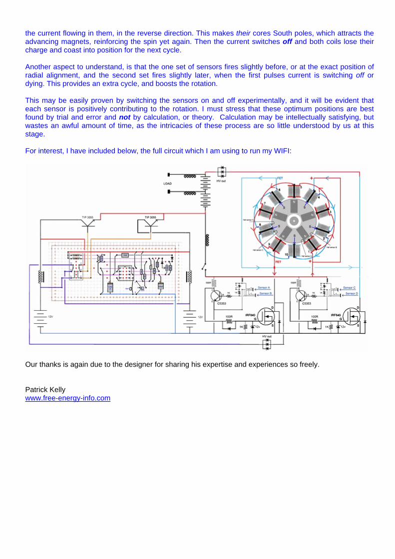
the current flowing in them, in the reverse direction. This makes their cores South poles, which attracts the advancing magnets, reinforcing the spin yet again. Then the current switches off and both coils lose their charge and coast into position for the next cycle. Another aspect to understand, is that the one set of sensors fires slightly before, or at the exact position of radial alignment, and the second set fires slightly later, when the first pulses current is switching off or dying. This provides an extra cycle, and boosts the rotation. This may be easily proven by switching the sensors on and off experimentally, and it will be evident that each sensor is positively contributing to the rotation. I must stress that these optimum positions are best found by trial and error and not by calculation, or theory. Calculation may be intellectually satisfying, but wastes an awful amount of time, as the intricacies of these process are so little understood by us at this stage. For interest, I have included below, the full circuit which I am using to run my WIFI:
Our thanks is again due to the designer for sharing his expertise and experiences so freely. Patrick Kelly www.free-energy-info.com