a simplified geometric and topological modeling of 3d
TRANSCRIPT

GIS Ostrava 2009 25. - 28. 1. 2009, Ostrava ___________________________________________________________________
A simplified geometric and topological modeling of 3D buildings enriched by semantic data: combination of surface-based
and solid-based representations
Chokri, KOUSSA, Mathieu, KOEHL
MAP-PAGE UMR 694 CNRS/MCC – INSA de Strasbourg, Graduate School for sciences and technics, 24 Boulevard de la Victoire, F-67084 Strasbourg, France
[email protected], [email protected]
Abstract. In the recent years, Geographical Information System (GIS) has demonstrated a high performance for managing large volumes of spatial data. To be integrated in a GIS, data have been structured trough conceptual, logic and physic modeling. In particular, conceptual modeling has consisted in the representation of real world data through a set of concepts linked by semantic relationships. This paper proposes a simplified geometric and topological conceptual model for 3D buildings. It takes inspiration from the two principle approaches for 3D modeling: B-Rep (Boundary Representation) and CSG (Constructive Solid Geometry). The motivation of the combination of such approaches is to take advantage of their strengths to represent buildings via different LODs (Levels of Detail). Thus, the proposed work consists in an algorithm that allows an automatic passage from surface-based representation to solid-based representation by extrusion. Then, this paper studies the enrichment of geometric and topological data by a set of semantic information to be integrated in the Spatial Database (SDB). The conceptual model has been translated into a PostgreSQL database. To create the final 3D model, the data have been queried from the database using a Java platform. Some samples are described to illustrate the implementation of the work concepts.
Keywords: 3D GIS, Modeling, Semantics, SDB
1 Introduction
Nowadays, the technological progress of both spatial data acquisition (Global Positioning System-GPS, Terrestrial Laser Scannar-TLS, etc) and computer tools (hardware, software, High-speed Internet, etc.) reached a high level of maturity. Therefore, handling 3D city models in 3D GIS has become an important research topic. Many cities have built recently their own 3D city models. But, 3D GIS goes beyond simple visualization of city objects. It gathers useful data for further interrogation and analysis. 3D spatial modeling is one of the most important issues in 3D GIS research [9]. It defines the data structure and organization. But, designing an object, such as a building, is a subjective matter [2]. It depends on the designer’s vision and the further operations on 3D models. However, respecting standards could be very useful for the interoperability with other applications working on spatial data. A considerable work has been done for more automatism and realism in 3D City models. The Open Geospatial Consortium (OGC) and the International Organisation for Standardisation (ISO) contribute in the development and implementation of standards for geospatial content and services. Thus, some standards and spatial data models were proposed such as GML (Geography Markup Language), ISO 191**, CityGML (City Geography Markup Language), etc. Also, a considerable research work has been done by many researchers around the world [12], [15] [17], etc. Therefore, many spatial data models have been appeared to meet diverse needs and to resolve many spatial data problems. This paper is organized as follows: It starts by a summary of some work done in the field of spatial data modeling. Then, it explains the fundamental notions of both CSG and B-Rep methods. After that, our approach for 3D urban objects modeling is described by some UML (Unified Modeling Language) class diagrams. Next, some results and experimentation are delineated to illustrate the implementation of the work concepts. Finally, a conclusion is drawn and our future work is explained.

GIS Ostrava 2009 25. - 28. 1. 2009, Ostrava ___________________________________________________________________
2 Related work
2.1 Geometric and topologic modeling
Modeling spatial data is a very important stage in the creation of a GIS. It allows representing the reality via a set of concepts related with semantic relationships. A model allows designer to early discover the anomalies that can appear, e.g. redundancy, deletion and update anomalies, etc. So, he can correct the model before exploring data. The comprehension of data structures and their relationships facilitates their management, manipulation and interrogation. A 3D city model can include the urban objects and the space in which they exist. In addition to geographic information, spatial data can also be described by attribute information [11]. Spatial objects can be simple (e.g. point, line, surface) or composed of a collection of objects (e.g. composed surface or composed solid). In the literature, many spatial data models have been proposed. The 3D FDS (Formal Data Structure) is based on four objects: Point, line, surface and body and four primitives: Node, arc, edge and face [12]. In this model, the topology depends on geometry. ISO takes its inspiration with this model but recommends a total independence between the topological model and the geometric model [16]. Another approach was introduced by [15] called TEN (TEtrahedral Network). TEN has four primitives: tetrahedron, triangle, arc and node. A body is composed of tetrahedrons, a surface of triangles, a line of arcs and a point of nodes [18]. Since the space is completely subdivided into tetrahedrons, the interiors of objects (e.g. buildings), as well as the open space, are also decomposed into tetrahedrons. Such subdivision is rather inconvenient for 3D man-made objects [18]. UDM (Urban Data Model) represents the geometry of a body or a surface by planar convex faces [4]. Figure 1 shows its conceptual schema. Fig. 1. Urban Data Model, Coors, 2002 Many other data models were proposed: SDM (Simplified Data Model) [17], and some Object-Oriented models e.g. 3D TIN-based OO model [1], OO-model of de La Losa and Cervelle [5], the Solid Object Management System (SOMAS) [14], etc. The International organisations such as OGC and ISO contribute in the definition of standards for the interoperability between heterogeneous applications working on spatial data. The ISO191**, defined by the TC 211 (Technical commitee 211), is a set of standards for geographic information. It includes the methods, the tools and the services for the acquisition, the analyses, the access, the presentation and the exchange of geographic information. In particular, ISO19107 defines a conceptual schema for the spatial features of geographic entities through geometric and topological objects. It defines four principle primitives: GM_POINT, GM_CURVE, GM_SURFACE and GM_SOLID. These primitives are represented in figure 2.
Fig. 2. ISO19107 Conceptual Schema

GIS Ostrava 2009 25. - 28. 1. 2009, Ostrava ___________________________________________________________________
The ISO19136 defines the encoding of ISO19107 in GML3. GML3 is a modelling language for geographic information. It is an OGC specification. It supports spatial and non spatial properties and implements the concepts of ISO 19100. GML3 contains a set of primitives wich include features, geometry, coordinates, Reference System, etc. GML distinguishes between geometry and feature (a feature represents physical entities, i.e. buildings, bridges, etc.). CityGML is a recent open model for the representation of 3D city objects. It is intended to become an open standard for the storage and the exchange of virtual 3D city models. It defines the properties of many topographic objects such as geometric, topological, semantic and appearance properties [13]. CityGML defines a geometric, topological and semantic model. It is based on GML3 specifications. The geometry model of GML 3 consists of primitives, which may be combined to form complexe, composite geometries or aggregates. For each dimension, there is a geometrical primitive: a zero-dimensional object is a Point, a one-dimensional a _Curve, a two-dimensional a _Surface, and a three-dimensional a _Solid [13]. CityGML is applied to various domains e.g. urban planning, disaster management, tourism, etc. Thus, it introduces a set of models such as Appearance Model, Digital Terrain Model, Transportation Model, Vegetation Model, etc. Many projects implement the OGC and ISO standards, i.e. Geoserver, Deegree, RedSpider, GeoOxygene, Oracle spatial, etc. Oracle Spatial is a commercial tool that handle spatial data via a set of primitives, i.e. point, linestring, polygon, solid, collection (multipoint, multicurve…), ring, composite_solid, composite_surface, etc. Oracle spatial uses some concepts of ISO and GML.
2.2 Semantics in spatial data
As GIS goes beyond simple data visualization, geographic data are often related to some semantic data. Thus, a SDB is more than a set of coordinates and measures. It includes both geometric and attribute data [7]. GML is a specification for the geographic information exchange, management and modeling. GML 3.0, the latest version, introduces a set of objects for relief description, coordinates, topology and measurement units. GML 3.0 don’t introduces a semantic representation for geographic objects except some significant names for different entities. According to our experience, CityGML is the most complete representation of both geometry, topology and semantics of urbain objects. Thus it introduces a set of models including appearance, geometry, topology, DTM (Digital Terrain Model), Building Model, Transportation Model, etc. At the semantic level, real-world entities are represented by features, such as buildings, walls, windows, rooms, etc. The description also includes attributes, relations and aggregation hierarchies (part-whole-relations) between features.
Fig.3. UML diagram of CityGML’s building model, part 1: pivotal class AbstractBuilding, Room, and thematic surfaces [13].

GIS Ostrava 2009 25. - 28. 1. 2009, Ostrava ___________________________________________________________________
Thus the part-of-relationship between features can be derived at the semantic level only, without considering geometry [13]. The building model is described by the figure 3. It shows a concrete subdivision of a building into sub parts.
2.3 Data modeling approaches
We distinguish two main methods to represent 3D objects: surface-based representation and solid-based representation. But, there are other methods e.g. simplex-based approaches, polyhedrons. Choosing a method or another depends on the future operations on the 3D objects, on data storage optimization, etc.
• B-Rep
Boundary Representations (also known as B-Rep) resemble the naïve representations in which the object is described in terms of its surface boundaries: vertices, edges and faces [6]. This method represents shapes by their limits. B-Rep distinguishes the geometry from the topology. Geometry describes the exact shape and position of each of the edges, faces and vertices. For example, the geometry of a vertex is defined by its position in space generally given by its coordinates (x, y, z). However, topology describes the relationships (connectivity) between faces, edges and vertices. B-Rep is used in Computer Aided Design (CAD). For example a building can be modeled as a collection of surfaces (walls, roofs) which share common edges.
Fig.4. Building modeled as a collection of surfaces In B-Rep, objects are more explicitly represented than in CSG. They are more detailed and give information about each face, edge and vertex. In a big city, is the representation of urban objects by their boundaries effective when storing and querying data? Voluminous data can decrease the performance of their interrogation and analysis. Thus, data optimization is a necessity to get an effective database. B-Rep has many advantages e.g. i) B-Rep is adapted to construct complex objects with exact definition of all surfaces of the final model. ii) B-Rep model can contain information of both geometry and interconnectivity between primitives. iii) Complex operations, i.e. solide volume calculation, check if a point belongs to a surface or a solid, etc. can be easily done in a B-Rep model. However, B-Rep requires a large disc space for data storage.
• CSG
Constructive Solid Geometry (CSG) is a modeling technique of solid objects. CSG solids are simple convex objects made out of intersecting coplanar faces [10]. A solid can be defined as a set of primitives shaped in volumetric instances such as cubes, cylinders, cones, spheres, etc. CSG models are constructed through three Boolean operations: the intersection (I ), union (U ) and subtraction
( ) of solid objects, some of which may be CSG objects themselves. The union of two objects results in an object that encloses the space occupied by the two given objects. Intersection results in an object that encloses the space where the two given objects overlap. Difference is an order dependent operator; it results in the first given object minus the space where the second intersected the first [8]. CSG is also used in CAD. CSG solid can be made up of a set of primitive shapes. For example, a building can be modeled as a union of the building body with the roof as shown in the next figure 5:
Fig.5. Building modeled as a union of two solids
U

GIS Ostrava 2009 25. - 28. 1. 2009, Ostrava ___________________________________________________________________
Many CAD systems work with CSG and form complex objects from primitive objects. CSG has many advantages e.g. i) Modeling a building as a set of blocks gives information about all building’s components so it is semantically more meaningful than B-Rep. ii) Modeling using primitives and Boolean operations is much more intuitive than specifying B-Rep surfaces directly (except for situations where the set of primitives is not appropriate for a given object) [3]. iii) Objects constructed by this technique have perfect boundaries whatever the level of detail. iv) CSG creates very realistic rendering (ray casting). However, we can easily reach complex construction operations which could decrease the performance of calculation and CSG don’t gives explicit information about solid surfaces.
3 Proposed model
3.1 Principle idea
The idea of this paper is to represent building in two different ways: - As a collection of surfaces: All building walls are represented by a collection of surfaces. Thus,
the concepts of B-Rep are used. Walls, windows and doors are represented by surfaces. The vertices coordinates of such surfaces are known.
Fig.6. Walls represented by a surface based representation
- As a collection of solids: In the reality, walls have a non negligebale thickness. This thickness can be noticed through windows and doors witch falling within walls. Walls are no longer B-Rep surfaces, they are rather CSG solids. Boolean operations are possible on these CSG solids, i.e, openings and intrusions in a wall are obtained by a difference operation between the solid corresponding to the wall and the solid corresponding to an opening or an intrusion. Not all the boundaries of such solids are mentioned.
Fig.7. Walls represented by a solid based representation
3.2 Algorithm
The contribution of this algorithm consist in the automatic passage from surface based representation to solid based representation. The technique used to carry out this algorithm is the extrusion of surfaces corresponding to the building walls. Then, walls become solids and so more realism.
Fig.8. Walls horizontal extrusion
The contribution of this algorithm is not the extrusion because it is a very known technique witch is used by the CAD tools. But, the main contribution is the use of the extrusion as a simple technique to move from surface based representation to solid based representation. The extrusion introduced in this paper is different to classic extrusion used in the field of building witch consists generally in the
(x,y,z)
Wall extrusion
GIS Ostrava 2009 25. - 28. 1. 2009, Ostrava ___________________________________________________________________
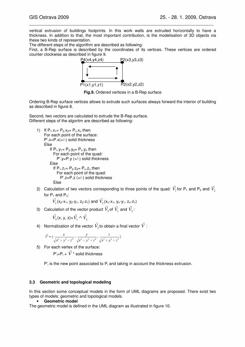
vertical extrusion of buildings footprints. In this work walls are extruded horizontally to have a thickness. In addition to that, the most important contribution, is the modelisation of 3D objects via these two kinds of representation. The different steps of the algorithm are described as following: First, a B-Rep surface is described by the coordinates of its vertices. These vertices are ordered counter clockwise as described in figure 9.
Fig.9. Ordered vertices in a B-Rep surface
Ordering B-Rep surface vertices allows to extrude such surfaces always forward the interior of building as described in figure 8. Second, two vectors are calculated to extrude the B-Rep surface. Different steps of the algoritm are described as following:
1) If P1.x1= P2.x2= Pn.xn then For each point of the surface: P’.x=P.x(+/-) solid thickness Else If P1.y1= P2.y2= Pn.yn then For each point of the quad: P’.y=P.y (+/-) solid thickness Else If P1.z1= P2.z2= Pn.zn then For each point of the quad: P’.z=P.z (+/-) solid thickness Else
2) Calculation of two vectors corresponding to three points of the quad: 1
V
rfor P1 and P2 and
2V
r
for P1 and Pn:
1
V
r(x2-x1, y2-y1, z2-z1) and
2V
r(xn-x1, yn-y1, zn-z1)
3) Calculation of the vector product 3
V
rof
1V
r and
2V
r:
3
V
r(x, y, z)=
1V
r∧
2V
r
4) Normalization of the vector 3
V
rto obtain a final vector V
r:
5) For each vertex of the surface:
P’i=Pi + Vr
* solid thickness
P’i is the new point associated to Pi and taking in account the thickness extrusion.
3.3 Geometric and topological modeling
In this section some conceptual models in the form of UML diagrams are proposed. There exist two types of models: geometric and topological models.
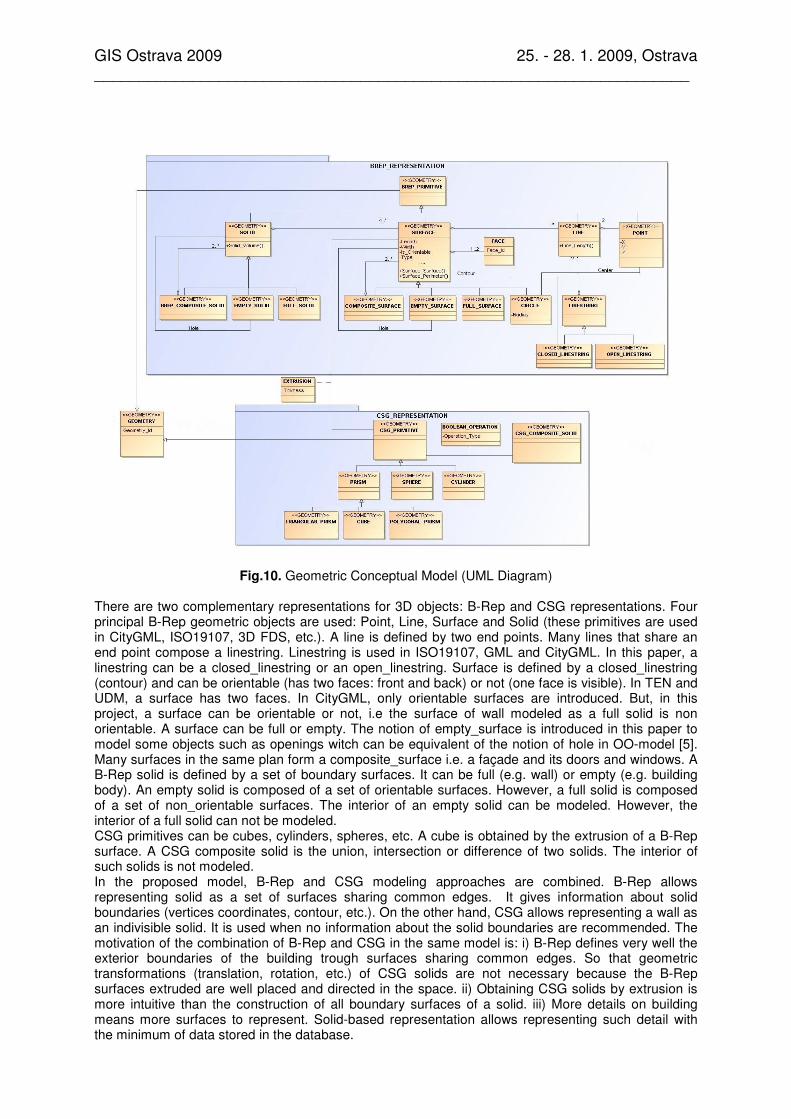
• Geometric model The geometric model is defined in the UML diagram as illustrated in figure 10.
P1(x1,y1,z1) P2(x2,y2,z2)
P2(x3,y3,z3)
P4(x4,y4,z4)
GIS Ostrava 2009 25. - 28. 1. 2009, Ostrava ___________________________________________________________________
Fig.10. Geometric Conceptual Model (UML Diagram)
There are two complementary representations for 3D objects: B-Rep and CSG representations. Four principal B-Rep geometric objects are used: Point, Line, Surface and Solid (these primitives are used in CityGML, ISO19107, 3D FDS, etc.). A line is defined by two end points. Many lines that share an end point compose a linestring. Linestring is used in ISO19107, GML and CityGML. In this paper, a linestring can be a closed_linestring or an open_linestring. Surface is defined by a closed_linestring (contour) and can be orientable (has two faces: front and back) or not (one face is visible). In TEN and UDM, a surface has two faces. In CityGML, only orientable surfaces are introduced. But, in this project, a surface can be orientable or not, i.e the surface of wall modeled as a full solid is non orientable. A surface can be full or empty. The notion of empty_surface is introduced in this paper to model some objects such as openings witch can be equivalent of the notion of hole in OO-model [5]. Many surfaces in the same plan form a composite_surface i.e. a façade and its doors and windows. A B-Rep solid is defined by a set of boundary surfaces. It can be full (e.g. wall) or empty (e.g. building body). An empty solid is composed of a set of orientable surfaces. However, a full solid is composed of a set of non_orientable surfaces. The interior of an empty solid can be modeled. However, the interior of a full solid can not be modeled. CSG primitives can be cubes, cylinders, spheres, etc. A cube is obtained by the extrusion of a B-Rep surface. A CSG composite solid is the union, intersection or difference of two solids. The interior of such solids is not modeled. In the proposed model, B-Rep and CSG modeling approaches are combined. B-Rep allows representing solid as a set of surfaces sharing common edges. It gives information about solid boundaries (vertices coordinates, contour, etc.). On the other hand, CSG allows representing a wall as an indivisible solid. It is used when no information about the solid boundaries are recommended. The motivation of the combination of B-Rep and CSG in the same model is: i) B-Rep defines very well the exterior boundaries of the building trough surfaces sharing common edges. So that geometric transformations (translation, rotation, etc.) of CSG solids are not necessary because the B-Rep surfaces extruded are well placed and directed in the space. ii) Obtaining CSG solids by extrusion is more intuitive than the construction of all boundary surfaces of a solid. iii) More details on building means more surfaces to represent. Solid-based representation allows representing such detail with the minimum of data stored in the database.

GIS Ostrava 2009 25. - 28. 1. 2009, Ostrava ___________________________________________________________________
• Topological model Topological conceptual model is based on three Boolean operations: Union, Difference and Intersection of geometric objects. Such operations are applicable on the four geometric objects mentioned in the geometric model (figure 10). To simplify, a class diagram is defined for each Boolean operation. Union
Fig.11. Topological Model: Union Operation In this model (figure 11), the concepts of multisolid, multisurface, multiline and multipoint of CityGML [13] are used. Union operations can be achieved only between similar objects. For example, the union of a solid and a point is meaningless. The union of two or many geometric forms generates a group of objects that can share or not common parts. Difference
Fig.12. Topological Model: Difference Operation
In this model (figure 12), like the union operation, difference operation can be carried out only between similar objects. We are interested only in solid and surface objects. For example, to obtain an opening in a wall, there are two cases: 1) If the wall is a surface, the difference is calculated between two surfaces (corresponding respectively to the wall and the opening). 2) If the wall is a solid, the difference is calculated between two solids (corresponding respectively to the wall and the opening). Difference operation is used also to add some details on walls (e.g. intrusion, extrusion, etc.). Intersection
Fig.13. Topological model: intersection Operations

GIS Ostrava 2009 25. - 28. 1. 2009, Ostrava ___________________________________________________________________
Detecting intersection between city objects is very important. It shows their common parts. Table 1 explains the results of intersection of the different geometric objects. It’s also important, in an urban space, to define the neighborhood relationships (adjacencies, distance to 1 or n neighbors, etc.) between buildings or groups of buildings. The relationships between two buildings can be: - Physic relationship: buildings can share common parts (generally intersection) or being geographically adjacent. - Semantic relationships: sharing the same properties (e.g. located in the same residential area, the same city, etc.).
Intersection Solid Surface Line Point
Solid Solid, surface, line, point
Surface, line, point
Line, point
*
Surface Surface, line, point
Surface, line, point
Line, point
*
Line Line, point Line, point Line, point
*
Point * * * *
Table 1. Intersection of geometric objects
3.4 Semantic model
Before the description of the semantic model, it’s very important to define some terms:
• Semantics Semantics is the study or science of meaning in language. It is the meaning or the interpretation of a word, sentence, or other language [19].
• Taxonomy In theory, the development of a good taxonomy takes into account the importance of separating elements of a group (taxon) into subgroups (taxa) that are mutually exclusive, unambiguous, and taken together, include all possibilities [20].
• Spatial semantics It is the study of the spatial data meaning witch can be formally expressed or unexpressed. Their interpretation is subjective and depends on the data users. Adding a semantic layer to spatial data allows GIS to answer both thematic and geometric queries. Semantic data are generally materialized by a set of descriptive data related to geometric data. The semantic level can be also formally represented via a taxonomy. Taxonomies are generally used to describe spatial entities properties and relationships. An SDB is more than a set of coordinates and measures. It contains other types of data. Thus, five layers are added to initial spatial data as follows:
Fig.14. Five level of representation of spatial data Firstly, the geometric level describes the shape and dimension of 3D objects. Secondly, the topological level describes the relationships between 3D objects. Thirdly, the geographical level describes the localization of 3D objects in the space. Fourthly, the semantic level gives additional
Spatial
data
Geometric level
Topological level
Geographic level
Semantic level
Documentary level

GIS Ostrava 2009 25. - 28. 1. 2009, Ostrava ___________________________________________________________________
information about 3D objects. Finally, the documentary level makes the link between 3D model and real information’s sources (e.g. photos, point clouds, etc.) in order to compare objects visualized on the screen with the real objects. This paper focuses only on geometric, topological and semantic levels. In this paper, there are two types of semantics:
• Semantics related to one object: such semantics concerne a single object and are not influenced by its relationships with other objects. They consist in attributes related to these objects, i.e, the name of a building, its type, etc. Such attributes can be: - Numeric: i.e, construction year of a building. - Qualitative: i.e, the building usage. Before querying such data, it is important to know the typology of attributes. All mathematic operations (addition, soustraction, etc.) or aggregation (maximum, minimum, etc.) are possible on numeric attributes but not on qualitative attributes. On qualitative data, only count and string comparison are possible.
• Semantics related to a group of objects: Such semantics are drawn from the relationships between objects. Relationships can be: - Binary: Relation between two objects, i.e, distance between them, adjacency, etc. - Tertiary:Relation between three objects, i.e checking if an object is between two objects. - N-ary: Relation between many objects, i.e, checking if many buildings exist in the same
residential area. Semantics can be also interpreted when observing objects visualized on the screen, i.e, we can observe that a building is located on the left of another. Thus, even the 3D visualization gives an important amount of semantics. Such semantics are not stored anywhere. They are implicit and interpreted from the 3D model visualized on the screen of a computer.
Fig.15. Building decomposition
Figure 15 shows the decomposition of a building and attributes describing it. A building is composed of a set of building parts (walls, building body, roof, etc.) and a set of detail objects (openings, intrusions, etc.). Each building component <<FEATURE>> has a geometric representation <<GEOMETRY>> as described in figure 10. Thus, geometric as thematic queries will be possible on these spatial data.
4 Experimentation and results
3D city objects details have been stored in a PostgreSQL database. Then, a java application has been designed to visualize and manipulate these objects. In a 3D GIS, 3D model must reflect the reality as much as possible. Therefore, some facade and roof details can bring more of realism in the 3D model. Certainly, textures and photos draped to city objects give a nice view and approach the reality. But, photos and textures are 2D plans. They are used just for the visualization of 3D objects. The real 3D consists in the reconstruction of city objects with the maximum of details. With this intention, this work aims to carry out an application with two main objectives: 1) 3D city objects are detailed as much as possible. 2) The minimum of data are stored in the database. Table 2 shows a building modeled with both surface-based and solid-based representations. Thickness of roofs and walls appears in the second column of the table.

GIS Ostrava 2009 25. - 28. 1. 2009, Ostrava ___________________________________________________________________
In a building, walls have a non negligible thickness witch can be noticed by doors and windows falling within the wall.
Table 2. Building modeled with Surface-Based Representation (left) and Solid-based representation (right)
With surface-based representation, windows and doors are obtained by the Boolean intersection of two surfaces (surface corresponding to the wall and surface corresponding to the window or the door). However, with solid-based representation, windows and doors are obtained by the Boolean difference between two solids (solid corresponding to the wall and the solid corresponding to the window or the door). The figure 16 shows doors and windows existing on a wall modeled as a surface and as a solid.
Fig.16. Door and windows on a wall represented as a surface (left) and as a solid (right) With a pragmatic point of view, the building shown in the table is stored in the database as follows:
Surface-based Representation Solid-based representation
Facades 4 surfaces 4 surfaces + 1 thickness
Roofs 2 surfaces 2 surfaces + 1 thickness
Doors 1 surface 1 surface
Windows 3 surfaces 3 surfaces
Total 10 data 12 data
Table 3. building storage in the database This table demonstrates that only with two added data (wall and roof thicknesses) surfaces are transformed to solids and so more realism. One might ask: the extrusion of a surface generates several other surfaces from witch some are hidden, so can this decrease the performance of the calculation? The response is no because only visible surfaces are calculated. Otherwise, hidden surfaces are calculated only when they appear in the screen. So the performance of the application will not be affected by the number of surfaces.

GIS Ostrava 2009 25. - 28. 1. 2009, Ostrava ___________________________________________________________________
5 Conclusion and future work
The aim of this study was the establishment of a 3D GIS for urban objects. In the first phase a conceptual model for 3D City objects which combines the CSG and B-Rep methods has been defined. The same urban object can be represented differently in this model. Thus, representation and properties of 3D objects change dynamically according to the level of details or zoom. This conceptual model has been translated into a SDB. Our model is not the most complete but it responds to the majority of our needs. We have combined CSG and B-Rep methods for two main purposes: More realism in our 3D model and more data optimization. In a second phase, we defined two conceptual models: geographic and semantic models to facilitate data comprehension and to obtain a semantically understandable model. These four models are associated to form an integrated conceptual model for our SDB. We work now on spatial data interrogation for visualization and analysis by using simulation techniques.
References
[1] Abdul-Rahman, A. The design and implementation of two and three-dimensional triangular irregular network (TIN) based GIS, 2000, PhD thesis, University of Glasgow, Scotland, United Kingdom, p.250.
[2] Abdul-Rahman, A. and Pilouk, M. Spatial Data Modeling for 3D GIS. Springer 2008 Berlin Heidelberg New York. ISBN 978-3-540-74I66-4.
[3] Brenner, C. Modeling 3D objects using weak CSG primitives. International Archives of Photogrammetry, Remote Sensing and Spatial Information Sciences ISPRS 2004, Istanbul. Vol. 35
[4] Coors, V., 2003. 3D GIS in networking environments. Computer, Environment and Urban Systems, Vol. 27, p. 345-357. ISSN 0198-9715 CODEN CEUSD5.
[5] De la Losa, A. and Cervelle, B. 3D topological modelling and visualisation for 3D GIS, Computers and Graphics, Volume 23, Number 4, August 1999 , pp. 469-478(10). ISSN 0097-8493.
[6] Jarroush, J. and Even-Tzur, G. Constructive Solid Geometry as the Basis of 3D Future Cadastre. FIG working Week 2004. Athens, Greece, May 22-27 2004.
[7] Joost, S. and Ertz, O. Conception de Bases de données Localisées et Temporelles (COBALT), Modélisation conceptuelle : un module de translation pour MapInfo. 2001. http://cs.ulb.ac.be/mads_tools.
[8] Kolb, C. Rayshade User's Guide and Reference Manual, 1994. http://www.graphics.stanford.edu/~cek/rayshade/doc/guide/guide.html.
[9] Khuan, C., Abdul-Rahman, A., and Zlatanova, S. 3D Spatial Operations in Geo DBMS Environment for 3D GIS. Computational Science and Its Applications – ICCSA 2007. Springer Berlin / Heidelberg, pp. 151-163. ISBN 978-3-540-74468-9.
[10] Leaddwerks Corporation 2006. What is Constructive Solid Geometry. http://www.leadwerks.com/files/csg.pdf.
[11] Lobo, A. Analysis of Spatial Information Detecting Spatial Pattern (Points), 2008. http://wija.ija.csic.es/gt/obster/Doctorat/aloboJEMES2007PointSpatPattern_v20080306.pdf.
[12] Molenaar, M. A Formal Data Structure for three dimensional vector maps. 4th
International Symposium on spatial data handling, 1990, Zurich, Swizerland.
[13] OGC. Candidate OpenGIS CityGML implementation Specification (City Geography Markup Language). Date: 2007-06-17. Reference number of this OGC® project document: OGC 07-062. Version: 0.4.0. Category: OGC Best Practices Document. Editors: Gerhard Gröger, Thomas H. Kolbe, Angela Czerwinski.
[14] Pfund, M. Topologic data structure for a 3D GIS, Proceedings of ISPRS, Vol.34, Part 2W2, 23-25 May 2001,
Bangkok, Thailand, pp. 233-237. ISBN 90-6164-122-5.
[15] Pilouk, M. Integrated modelling for 3D GIS, PhD thesis, ITC, 1996, The Netherlands.
[16] Ramos, F. A multi-level Approach for 3D modelling in Geographical Information System. Symposium Geospatial Theory, Processing and Applications. Ottawa, 2002.
[17] Zlatanova, S. 3D GIS for Urban development. 2000, PhD thesis at Graz University of Technology.
[18] Zlatanova, S., Abdul-Rahman, A. and Shi. W. Topology for 3D spatial objects. International Symposium and Exhibition on Geoinformation 2002, 22-24 October, Kuala Lumpur, Malaysia. Kluwer Academic Publishers. ISSN:1384-6175
[19] http://www.answers.com
[20] http://www.ingentaconnect.com