a simulation study on joint velocities and end effector...
TRANSCRIPT

International Journal of Advanced Mechatronics and Robotics (IJAMR)Vol. 3, No. 1, January-June 2011; pp. 9-20; © International Science Press, ISSN: 0975-6108
A Simulation Study on Joint Velocities and End EffectorDeflection of a Flexible Two Degree Freedom
Composite Robotic Arm
A. Purushotham1 & J. Anjaneyulu2
1Professor, Mechanical Engineering, Sreenidhi Institute of Science & Technology,(An Autonomous Institution) Hyderabad-501 301, India
E-mail: [email protected] Professor, Mechanical Engineering, Vasavi College of Engineering, Hyderabad- 501 031, India
E-mail: [email protected]
ABSTRACT
The dynamic response of joint velocities and end effector deflection of a two degree-of-freedomplanar composite robot arm is presented in this paper. For the purpose of analysis, the material oflinks of the arm of the robot are assumed to be fabricated from either aluminum or laminatedcomposite materials. The numerical solution to obtain the joint velocities and end effector deflectionsof the robot arm is sought in MATLAB Code. The simulation studies examine the interactionbetween the flexible and the rigid body motions of the robot arm. After numerical investigation, it isfound that there is a advantages of using composites in the structural design of robotic manipulatorsas composite arms improves in the accuracy end effector path.
Keywords: Flexibility, End Effector, Advanced Composites, Dynamic Modeling.
NOTATION
[m] : Inertia matrix of manipulators of size 2x2
l1
: Rotating Link length
l2
: Sliding link length
I1
: Mass moment inertia of rotating length about at C.G
I2
: Mass moment inertia of sliding link about its C.G
g : Acceleration due to gravity
d : Linear displacement of sliding link
θ : Angular displacement of rotating link
q : Generalized coordinates variablesT
dd v d
t t
∂θ ∂ θ ω = = θ ∂ ∂

10 International Journal of Advanced Mechatronics and Robotics
D : Inertia matrix of manipulator
h : Centrifugal and coriolis component matrix
G : Gravity matrix
(a,b) : Linearization point
X : State space variable vector
T : Joint torque at the joint 1
F : Displacement force at Joint 2
(xg,y
g) : Coordinates of CGs in inertial frame
A : Amplitude vector
ρ : Density of link
E : Young’s modulus
M : Mass matrix
K : Stiffness matrix
1. INTRODUCTION
Many robotic applications require fast and precise robot arms. Generally fast maneuverabilityis achieved by lightweight robotic manipulators. However, lighter structures fabricated fromconventional metals, tend to be weaker and would undergo large deformations; thusdeteriorating the accuracy of the path of end effector of many industrial robots. The accuracyof end effector path can be significantly improved by modifying their existing structuraldesign with the focus being on maximizing the stiffness-to-weight ratio of the arms. Thehigher stiffness to weight ratio is achieved by either optimizing the geometric dimensions ofthe structure [1, 2], or by implementing lighter and stiffer materials such as composites[2, 3].A quick and relatively inexpensive way of evaluating such modifications is simulationstudies. Therefore, An dynamic model is derived which include all the coupling terms betweenthe rigid and the flexible motions of the manipulator and couples the rigid body motion of thestructure with its linear elastic deformations. In literature, three methods, the assumed modesmethod [4-6], the finite element method [7-15] and the lumped mass method [16 and 17],are commonly available to get the approximate solution of the dynamic model of the flexiblerobotic manipulators. Most studies related to dynamic modeling of flexible robot arms consideropen-kinematic chains with revolute joints. Very few papers address the modeling problemof robotic manipulators with prismatic joints [5, 6, 14, 15]. Chalhoub and Ulsoy [5] used theassumed modes method to discretize the elastic deformation of a flexible link connected toa prismatic joint. The effect of the variation of the length of the flexible beam on the admissiblefunctions was considered in a quasi-static fashion. Wang and Wei [6] derived expressionsfor admissible functions that are dependent on spatial coordinate and time. Song and Haug

A Simulation Study on Joint Velocities and End Effector Deflection of a Flexible… 11
[14] and Pan et al., [15] developed a general formulation to model flexible mechanisms withrevolute and prismatic joints. The derivation is based on the finite element method. Thecompatibility conditions associated with revolute and prismatic joints are imposed by kinematicconstraints.
The equations governing the rigid and flexible motions of open- kinematic chains arecoupled and highly nonlinear. The nonlinearity is large and cannot be eliminated as theseterms influence the dynamic response large extent when bodies treated highly flexible andhigh velocities. Therefore, the equations of motions have to be solved with these terms. Inthis paper, the solution of the dynamic model for a planar, two-link, flexible robotic manipulatoris done numerically using Gear’s Method [14] with the help MATLAB software. The dynamicequations developed for this flexible manipulator is similar to the dynamic models developedby Azhdari A et.al [15]. The paper has been organized in three sections. The description ofmanipulator structure is given in the section-2 and Numerical results are presented in thesection-3. In the last section, the work done in this study is summarized and the mainconclusions are highlighted.
2. DESCRIPTION OF DYNAMIC MODELDEVELOPED
2.1 Description of Manipulator
The manipulator shown in Figure. 1 consist of two links. Link 1 rotates about vertical memberwhile link2 slides in link one. The links which are modeled solid circular cylinders beams
Figure 1: Geometry of the Manipulator

12 International Journal of Advanced Mechatronics and Robotics
considered as rigid bodies studies. These circular cylinders beams made hallow and consideredas flexible links. The flexible links are modeled as beams with annular cross-sections. Thedynamic analysis is carried out with solid and hallowlinks assumed to be made up of Aluminumand hallow links assumed to be made up of Composites. The material properties and geometricdimensions of the system are given in Table I. The purpose of simulation studies is toexamine the effect of the elastic deformation when arms are manufactured with light structurelinks of hallow cross section made up of composites and to demonstrate the advantages ofincorporating composites in the structural design of robotic manipulators.
Table IGeometric and Material Properties of Links of Robotic Arm
Geometric Property Material Property
Outer diameter of link1 (cm) 2 Mass density of Aluminum (Kg/m3) 2.643*103
Inner diameter of link1 (cm) 1 E of Aluminum (N/m2) 0.7*1011
Length of Rotating Link1 (cm) 60-120 G of Aluminum (N/m2) 0.26*1011
Outer diameter of link2 (cm) 1 Mass density of Graphite /Epoxy 1.3*103
(Kg/m3)
Inner diameter of link2 (cm) 0.5 E of Graphite /Epoxy (N/m2) 1.727*1011
Length of sliding Link2 (cm) 50-100 G of Graphite /Epoxy (N/m2) 0.0376*1011
2.2 Dynamic Equation Formulation
The Euler-Lagrange equations of motion are generally applied to derive the dynamicequationsof a serial manipulator, which possess n degrees of freedom. The dynamic equations of aserial rigid manipulator [15] in terms of joint variables [q] given as:
( )[ ] ( , ) ( )m q h q q G q T+ + = (1)
w h e r e , m(q) is the inertia matrix of manipulator, h(q,q) is a n×n matrix related to thecentrifugal and Coriolis terms, G(q) Gravity terms and T is the joint generalized force/torques.
The link’s mass and the center of mass of each link in D-H frame are required to formthe inertia matrix m, Corilisis and centrifugal matrix h and gravity matrix G and they aregiven by
( )( )2 2 2
21 1 1 2 22
22
1 1 2 1
2 2
0 020
– 000
( ) cos
sin
m dm l I m d Iv
m dm vd
m l m d g T
m g T
+ + + ω θ + ω +
+ θ
+ = θ
(2)
Based on the geometry details, mass properties and relative positions of links, Thematrices D, h and G are evaluated. The D, h, and G matrices are separately evaluated for

A Simulation Study on Joint Velocities and End Effector Deflection of a Flexible… 13
the manipulator structure when links are solids with aluminum, hallow with aluminum andhallow with composites.
Following linearization scheme adopted for centrifugal and coriolis components ofdynamicequation at a critical point of configuration (a, b)
( , ) ( , ) ( – ) ( – )f ff d f a b a a b
d
∂ ∂θ = + θ +∂θ ∂
(3)
The state space variable is introduced as given below:
1
2
3
4
x
xX
x d
x v
θ ϖ = =
(4)
Now the dynamic equation converted in to state space as shown below:
X AX BU
Y CX D
= += + U
(5)
[A] is square matrix of size of 4 by 4, [C] is output matrix and input matrix is given by
11
22
0
1and is null matrix
0
1
mB
m
=
D(6)
The input torques has been defined as given below:
TU
F
=
(7)
This equation is solved using MATLAB code to obtain joint variables: Joint angles andjoint velocities. Then the linear displacement, velocities and accelerations are obtained byusing following positional relations:
1 1
1 1
2
2
cos
sin
cos ( , )
sin ( , )
g
g
g g
g g
x l
y l
x d x d
y d y d
= θ
= θ
= θ = θ
= θ = θ(8)
2.3 Finite Element Formulation
The two links are divided in to j number of element with the idealization of frame elements.The number of nodes made is k.

14 International Journal of Advanced Mechatronics and Robotics
Then the finite element equation is given by:
Ma Ka+ = F (t) (9)
The solution of finite element equation can be sought with
a = A sin ωt (10)
Where A is nodal displacements vector which is given by
A =
1
2
k
a
a
a
⋅ ⋅ ⋅
(11)
M is Global mass matrix; K is Global stiffness matrix and F Global load vector. The eachelement Mass Matrix is given by
2 2
3 2 3
2
3
3 6
13 11 9 –1335 210 70 420
13105 420 140
3
13 –25 210
105
0 0 0 0
0
0
0 0
Al Al
Al Al Al Al
Al Al Alj
Al
Al Al
Al
M
ρ ρ
ρ ρ ρ ρ
ρ ρ ρ
ρ
ρ ρ
ρ
=
(12)
Each Element stiffness matrix is given by
3 2 3 2
2
3 2
–
6 612 –12
–6 –2
–612
4
0 0 0 0
0
0 0
0 0
EA EAl l
EI EIEI EIl l l l
EI EIlj l
EAl
EIEIl l
EIl
K
=
(13)
The natural frequencies i of overall manipulator can be obtained with the followingequation:
2– iK Mω = 0, i = 1 to k (14)

A Simulation Study on Joint Velocities and End Effector Deflection of a Flexible… 15
The amplitude equation for each natural frequencies i is given by
2– iiK M A ω = 0 (15)
From the amplitude equation, the Amplitude vectors are for each frequency obtained asAi.
The Amplitude vectors are normalized with following relations:
where [ ]i
Ti i iN i
i
AA S A M A
S = = (16)
Then the normalized vector of all amplitude can be written as
AN
= 1 2, , , kN N NA A A … (17)
The global load vector is written as
F =
1
1
2
2
0
0
x
y
x
y
kx
F
F
F
F
F
⋅
⋅ ⋅
(18)
Note that each term of Force vector is to be expressed as
F = F0 sin ϖt (19)
The inertia forces at nodes corresponding to COG are obtained with accelerationswhich are found from dynamic equation and are given by
Fx(t) =
1 1
2 2
g
g
m x
m x
(20)
Fy(t) =
1 1
2 2
g
g
m y
m y
(21)
Some F the nodal forces may be taken as Zero based on the nodal boundary conditions.

16 International Journal of Advanced Mechatronics and Robotics
The normalized Force vector f is obtained as:
f = AN
F (22)
The generalized matrix P is obtained as
P = 2 2
( ,1), 1 to
( – )m
f mm k=
ω ϖ (23)
The final solution, i.e. nodal amplitude vector is calculated as:
A = AN
P (24)
3. NUMERICAL RESULTS AND DISCUSSION
In the numerical study, three models have been developed. The manipulator made up oflinks with circular solid cylinder with Aluminum is termed as mode-l, manipulator made upof links with hallow circular cylinder with Aluminum is termed as mode-2 and manipulatormade up of links with hallow circular cylinder with composites is termed as model-3. Theeffect of the flexibility of the links on the rigid body behavior of the robot arm is illustratedby comparing the joint velocities and End effector deflection obtained from these threedifferent models of the robotic manipulator. The saw-tooth profile of force and torque, isapplied at the joints of the manipulator in all cases.
The joint 1 is a rotary joint and a torque shown in Figure 2 is assumed. At joint 2, a force(shown in figure 2) similar variation of joint 1 is assumed to be applied in the model. Thevariation of applied in put indicate that input at joints is gradually increases and then suddenlybrought to zero. This type of input generally comes across in many manipulators.
Figure 2: Applied Joints Inputs
The response obtained from the first model, whose both links are assumed to be rigid(rigid-rigid), is given in Figures 3a and 3b. The results of the second model, which includesthe flexibility of both links (flexible-flexible), are shown in Figures 4a and 4b. A comparison
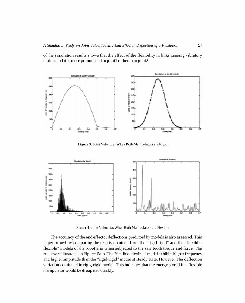
A Simulation Study on Joint Velocities and End Effector Deflection of a Flexible… 17
of the simulation results shows that the effect of the flexibility in links causing vibratorymotion and it is more pronounced in joint1 rather than joint2.
Figure 3: Joint Velocities When Both Manipulators are Rigid
Figure 4: Joint Velocities When Both Manipulators are Flexible
The accuracy of the end effector deflections predicted by models is also assessed. Thisis performed by comparing the results obtained from the “rigid-rigid” and the “flexible-flexible” models of the robot arm when subjected to the saw tooth torque and force. Theresults are illustrated in Figures 5a-b. The “flexible -flexible” model exhibits higher frequencyand higher amplitude than the “rigid-rigid” model at steady state. However The deflectionvariation continued in rigig-rigid model. This indicates that the energy stored in a flexiblemanipulator would be dissipated quickly.

18 International Journal of Advanced Mechatronics and Robotics
(a) Rigid-Rigid (b) Flexible-Flexible
Figure 5: Deflection of End Effector
The superiority of advanced composites over conventional metals is demonstrated bycomparing the response of an hallow aluminum arms to the response of a hallow graphite/epoxy arms. The properties of graphite/epoxy composites of laminations type [–45°/–45°]and type [+40°/40°] have been used in evaluation of mass and inertia matrices for thedynamic models. A valid comparison between the performance of manipulators which aremade of aluminum materials and graphite/epoxy materials is done by prescribing thedeflections of end effector of the robotic arm arm. This is because graphite/epoxy is lighterthan aluminum and the application of a set of saw-tooth torque and force to the robot armwould generate higher speed, and consequently, higher inertial forces in the composite armthan in the aluminum one. Figure 6 shows that the composite arm exhibits less vibration thanthe arm made of aluminum.The [+40°/40°] laminated arm has the lowest end effector
(a) Composite of type [–45°/–45°] (b) Composite of type [–40°/–40°]
Figure 6: Deflection of End Effector

A Simulation Study on Joint Velocities and End Effector Deflection of a Flexible… 19
deflection than [–45°/+45°] laminated composite. (See Figure 6a and 6b). A slight changeof the angle of fiber orientation in the graphite/epoxy, from 45° to 40° demonstrates less endeffector deflections.Changing the orientation of lamina changes the transformed stiffnesscoefficients. Thus transverse deflection of [–40°/+40°] laminate is smaller than the onecorresponding to [–45°/+45°]4 laminate.
4. SUMMARY AND CONCLUSIONS
In this work, the results of dynamic model of a planar, revolute-prismatic robot arm arepresented. Both links of the robotic manipulator are considered to be rigid, flexible andmade up of composites. All coupling terms between the rigid and the flexible motions of therobot arm are included in the model. The joint velocities and deflections of the manipulatorare simulated by using MATLAB code. As the governing equations of motion which are inthe form a set of stiff, coupled and highly nonlinear, Gear’s method, which is best suited tohandle stiff differential equations, is employed to obtain the numerical solutions.
The effect of the flexibility of links on motion of the manipulator is significant andcannot be ignored in the context of accurate path track of end effector. In addition, theinclusion of the flexibility in the links of the arm leads to an overestimated end effectordeflections at steady state.
The use of advanced composite materials in the fabrication of lightweight and highspeedrobotic manipulators leads to improved end effector positional accuracy and to lower torque/force requirements at the joints. The selection of the angle of fiber orientation and materialproperties in the design of a robot arm plays an important role in the reduction of the endeffector deflections.
ACKNOWLDGMENTS
Authors also thank Dr. T.Ch.SivaReddy, Head Mechanical Engg. Sreenidhi Institute ofScience and Technology (An Autonomous Institution) Hyderabad, A.P. India-501301 for hisencouragement and help in carrying out this research work.
REFERENCES
[1] Imam, I. and Sandor, G. N., “High Speed Mechanism Design: A General Analytical Approach”, ASMEJournal of Engineering for Industry, 97(2), 1975, 609-628.
[2] Liao, D. X., Sung, C. K., and Thompson, B. S., “The Design of Flexible Robotic Manipulators withOptimal Arm Geometries Fabricated from Composite Laminates with Optimal Material Properties”, TheInternational Journal of Robotics Research, 6(3), 1987, 124-137.
[3] Thompson, B. S. and Gandhi, M. V., “The Finite Element Analysis of Mechanism Components madefrom Fiberreinforced Composite Materials”, ASME Paper 80-Det-63.
[4] Book, W., J., Maizza-Neto, O., and Whitney D. E., “Feedback Control of Two Beams, Two Joint Systemswith Distributed Flexibility”, ASME Journal of Dynamic Systems, Measurement and Control 97(4), 1975,424-431.

20 International Journal of Advanced Mechatronics and Robotics
[5] Chalhoub, N. G. and Ulsoy, A. G., “Dynamic Simulation of a Leadscrew Driven Flexible Robot Arm andController”, ASME Journal of Dynamic Systems, Measurement and Control, 108(2), 1986, 119-126.
[6] Wang, P. K. C. and Wei, J. D., “Vibrations in a Moving Flexible Robot Arm”, Journal of Sound andVibration, 116(1), 1987, 149-160.
[7] Sunada, W. H. and Duhowsky, S., “On the Dynamic Analysis and Behavior of Industrial RoboticManipulators with Elastic Members”, ASME Journal of Mechanisms, Transmissions, and Automation inDesign, 105(1), 1983, 42-51.
[8] Shabana, A. and Wehage, R. A., “Variable Degree-of-freedom Component Mode Analysis of InertiaVariant Flexible Mechanical Systems”, ASME Journal of Mechanisms, Transmissions, and Automation inDesign, 105(3), 1983, 371-378.
[9] Turcic, D. A. and Midha, A., “Generalized Equations of Motion for the Dynamic Analysis of E lasticMechanism Systems”, ASME Journal of Dynamic Systems, Measurement and Control, 106(4), 1984,243-248.
[10] Usoro, E. B., Nadira, R., and Mahil, S. S., “A Finite Element/Lagrange Approach to Modeling LightweightFlexible Manipulators”, ASME Journal of Dynamic Systems, Measurement, attd Control, 108(3), 1986,198-205.
[11] Thompson, B. S. and Sung, C. K., “A Survey of Finite Element Techniques for Mechanism Design”,Mechanism and Machine Theory, 21(4), 1986, 351-359.
[12] Naganathan, G. and Soni, A. H., “Nonlinear Modeling of Kinematic and Flexibility Effects in ManipulatorDesign”, ASME Journal of Mechanisms, Transmissions, and Automation in Design, 110(3), 1988,243-254.
[13] Gordaninejad, F., Chalhoub, N. C., Ghazavi, A., and Azhdari, A., “Finite Element Modeling of a LaminatedComposite-materials Flexible Robot Arm”, in D. Hui and T. J. Kozik (Eds.), Advances in Macro- Mechanicsof Composite-Material Vessels and Components, ASME PVP, 146, 1988, 77-84.
[14] Song, J. O. and Haug, E. J., “Dynamic Analysis of Planar Flexible Mechanisms”, Computer Methods inApplied Mechanics and Engineering, 24, 1980, 359-381.
[15] Gear C.W., Shampine L.F., “Solution of Stiff Differential Equations”, Journal of Industrial and AppliedMathematics, 21, No. 1, January 1979.
[16] Azhdari A.Chalhoub N.G., Gordaninejad F., “Dynamic Modeling of a Revolute –Prismatic Flexible RobotArm”, Thesis University of Nevada-Reno, 1989.