a stereoscopic image-based approach to virtual environment...
TRANSCRIPT

Vajirasak Vanijja and Susumu Horiguchi
68
A Stereoscopic Image-Based Approach to Virtual Environment Navigation
Vajirasak Vanijja ([email protected] ) Susumu Horiguchi ([email protected])
Muti-media System Lab.
Graduate School of Information Science, Japan Advance Institute of Science and Technology,
1-1, Asahidai, Tatsunokuchi, Ishikawa, Japan, 923-1211
Abstract Image-Based Virtual Environments are
alternative approaches for virtual reality applications to generate real world scenes in virtual environments with low computation cost. This paper presents an approach to creating interactive image-based virtual reality environments in stereoscopic modes using binocular stereoscopic omni-directional image sequences. The Omni-directional Binocular Stereoscopic images are generated from four images by using an omni-directional camera. All captured images are re-rendered to a stereoscopic image pair. The images are digitally warped to a cylindrical view-plane to minimize the distortion. The images are evaluated by using a stereo matching algorithm. After organizing the images by our implemented system, the user can interact (zoom or pan) with the scenes and freely control movement around a specific area by “hopping” from one position to another. A new technique, which is used to interpolate the image to smooth the hopping, is also proposed and evaluated.
Keyword: Stereoscopic image, Virtual reality, Environment map, Omni-directional image, View interpolation.
1. Introduction Virtual environment navigation is a
large field of research. There are two main approaches to implementing the virtual environment. The first is 3D computer graphics, which can generate the virtual environment using the power of rendering hardware. The advantage of 3D computer graphics is that the creator can synthesis an environment for arbitrary presentation but the rendering quality and scene complexity are often limited because of the real-time constraints. A real world scene is very complex and image creation takes a long time using this approach. Another approach, which can implement real world scenes with lower computational power, is an image-based approach. The image-based approach has been used in the commercial product QuickTime VR[1], a virtual reality extension to Apple Computer’s QuickTime digital multimedia framework. QuickTime VR projects the whole environment image onto a simply shaped view plan and can interact with the user in an effective way. However some limitations remain. These include displaying scene images with stereoscopic sense and restriction of the navigation path.
There are approaches to use omni-directional panoramic images for virtual reality application. Nayar et al. [2][3] proposed a method to capture the whole

A Stereoscopic Image-Based Approach to Virtual Environment Navigation
International Journal of The Computer, the Internet and Management Vol. 14.No.2 (May - August, 2006) pp 68– 81
69
environment using one shot from a 360º camera. Peri et al. [4] described a method for the creation of a perspective view of an interactive image scene from an image created by a 360º camera. Onoe [5] presented an online perspective image generation. Aliaga [6] used Plenoptic stitching, which used an image-based rendering method to re-construct a 3D interactive work-through system from omni-directional panoramic image sequences. The plenoptic stitching approach is an effective way for conducting virtual reality environment navigation with hybrid approaches but is still difficult to implement for stereoscopic views. The authors[7] proposed a monoscopic display method for 360° interactive video scenes with multi-directional moving capability.
The 3D computer graphics method has the capability to display stereoscopic images because the computer generates all environment images [8][9]. It is possible to render both eye views to the user. Even the most recent image-based virtual reality navigation systems cannot display in stereoscopic mode because it is quite complicated to produce binocular stereoscopic images in omni-direction views from normal photographic processes. The binocular stereoscopic panoramic image pair method was first presented by Peleg [10] but a large number of images have to be taken to generate an omni-directional binocular stereoscopic images pair. Another approach to generating binocular stereo image from an omni-directional image sequence was presented by Yamaguchi [11]. This can render binocular stereo images in real-time mode. However, their interactive images have some limitations of orientation-dependence.
This paper presents an image-based approach for virtual environment navigation based on the QuickTime VR image-based approach [1], and is a personal computer-based application. The system uses real-time image processing to generate binocular
stereoscopic viewing effects. The images that we currently use are cylindrical panoramas. The panoramas are orientation-independent because each of the images contains all the information needed to look around in 360˚. A number of these images can be connected to form a walkthrough sequence. The use of orientation-independent images allows a greater degree of freedom in interactive viewing and navigation. These images are also more concise and easier to create than movies. The image-based approach to virtual reality navigation is discussed in section 2. We describe the method of synthesizing the omni-directional binocular stereoscopic images in section 3. Section 4 shows the user’s interface design and display loop’s algorithm, which lets the user navigate around the virtual environment freely in eight alternative directions. The system evaluations, which perform stereo matching and interpolated zooming image quality estimation are presented in section 5. We summarize all ideas and results of the experiments in the conclusion of section 6. Some future work and possible applications are also discussed in section 6. 2. Image-based Approach to Virtual Reality Navigation
2.1 Quick Time VR
One approach to synthesizing and
navigating in a virtual environment, which has been used extensively in the video game industry, is branching movies. Multiple movie and image segments depicting spatial navigation paths are connected together at selected branch points. The user is allowed to move on to a different path only at these branching points. The approach usually uses photography or computer rendering to create the movies. A computer-driven analog or digital video player is used for interactive playback. The commercial product, QuickTime VR, is a good example of this

Vajirasak Vanijja and Susumu Horiguchi
70
approach. The QuickTime VR method is similar to the movie-based approach and shares the same advantages. It differs in that the movies are replaced with “orientation-independent” images and the movie player is replaced with a real-time image processor. QuickTime VR is an image-based approach to virtual environment navigation [1] and enables the user to pan and zoom to view a section of a 360° cylindrical panoramic image of a real environment scene. Walking in a space is currently accomplished by jumping to different panoramic points. However, they lacked information about zooming and distance between branch points. This paper presents an idea for organizing and displaying the omni-directional binocular stereoscopic images while extending the moving path of the user.
2.2 Omni-directional Panoramic Image
A panoramic image is an image having a
wide field-of-view, up to 360º. Panoramic image can be captured or generated in several ways, among them:
- By using a single camera and special
lenses such as a conical, spherical, hyperbolic or parabolic mirrors. Through the mirror a single image can view the entire scene, or at least a very large field-of-view.
- By using multiple cameras, or one rotating camera, and stitching their images into a single panoramic image (called “mosaicing”)
It was a common belief that each
panorama should have a single viewpoint, known as the “center of projection”. A panorama can be viewed as a projection of the scene onto a cylinder or a sphere through this viewpoint. It was necessary to have a single viewpoint panorama in order to create mathematically correct narrow field-of-view images from the panoramic image.
3. Omni-directional Binocular Stereoscopic Images
3.1 Omni-directional Binocular
Stereoscopic images from a single camera Peleg [10] first presented a method of
generating stereo panoramic image from a single rotating camera. Intuitively, creating panoramic stereoscopic images appears contradictory. Pictures taken by ordinary cameras, and regular panoramic images, are taken from approximately a single viewpoint. A stereo pair is comprised of two images taken from two different viewpoints, corresponding to the locations of the two eyes. Two panoramic images, taken from two different viewpoints, can be viewed as a stereo pair in a perpendicular direction to the line connecting the two viewpoints. However, the two images will fail to give stereo perception when viewed in the direction of the line connecting the two viewpoints since images from the two cameras are behind each other.
If a 3D model of a panoramic environment is provided [8], two images could be rendered for every desired viewing direction. It was proposed in [9], for the first time, that two panoramic images are sufficient to generate a stereo view in all directions. In this section, a method of capturing and generating an omni-directional binocular stereo pair by a new type of multiple-viewpoint image projection is described. We also show how a single omni-directional lens with a digital still camera can create these projections, which is much more appropriate and faster than the previous approaches.
3.2 Viewpoint Projections
Regular images are created by a
perspective projection. Scene points are projected onto the image surface along a

A Stereoscopic Image-Based Approach to Virtual Environment Navigation
International Journal of The Computer, the Internet and Management Vol. 14.No.2 (May - August, 2006) pp 68– 81
71
projection line passing through a single point, called the “optical center” or “viewpoint”. For some special mosaicing applications, images can be projected through more than one viewpoint such as a stereo panorama [10]. Two small strips for the left and right eyes are cut from photographs taken by a static rotating camera. The images are taken from one position but multiple virtual viewpoints are simulated. A disadvantage of the method is that a large number of photos must be taken for a panoramic stereo pair because normal lenses are limited by the field-of-view.
An omni-directional camera can capture a very large field-of-view, in which the entire 360º field-of-view is captured with one image. If two images are taken by an omni directional camera, only some parts of the images can be used for the stereoscopic pair (see Figure 1). The distance between two eyes (x) is used to identify the position of the camera. α is the decomposition angle of the
360° circular image. A stereo pair will be recognized within angle θ when;
ε is a small additional angle of α
which still has stereoscopic characteristics. The angle ε can be varied because it is used for overlapping segments of the stitching process (in section 3.3). However, four omni-directional images from four viewpoints can complete the stereoscopic characteristic in all viewing directions. Note that the stereoscopic viewpoints and user’s position are difference. In this case, the user’s position is in the center of all four viewpoints, as shown in Figure 2.
The next section will show image processing details of the perspective omni-directional image conversion and mosaicing all the image portions together to produce a stereoscopic image pair.
N
S
EW
NW NE
SESW
N
S
EW
NW NE
SESW
Xθεε
α
Figure 1, Two circular images from 360º cameras. Only some parts can generate stereoscopic view.

Vajirasak Vanijja and Susumu Horiguchi
72
3.3 Image Capturing and Image processing
The omni-directional perspective
panoramic images can be produced from circular images of omni-directional lenses and cameras [2][3][4]. Creating two panoramic images for stereoscopic viewing, omni-directional images have to be captured from four different positions. Some portions of the images are then selected to re-render two stereoscopic images. The capture position must be fixed to minimize the distortion effect. The distance between two stereo viewpoints (x) is set to 6 cm. An omni-directional lens attached to a high-resolution digital still camera is used to capture the images. Four of the omni-directional images are taken, analyzed and synthesized into new omni-directional stereoscopic images pairs at each observer’s position (see Figure 2). The 1L-8L segments are used for generating the left-eye’s omni-directional panoramic image and the 1R-8R segments are used for generating the right-eye’s panoramic image.
A perspective converter program from a 360º circular image to a 360º perspective panoramic image has been implemented. The sixteen perspective segments from four converted 360º perspective panoramic images are cut according to the angle θ and a stitcher program, which implemented using algorithm of Szeliski [12], is used to re-render a new 360º binocular stereoscopic pair. In the stitcher program, the user can identify the similar pixels to match all segments. The overlapped parts, which are converted from the ε angle, can simplify the image stitching. We evaluate the output panoramic stereo pair with a cooperative algorithm for stereo matching and occlusion detection [13] in section 5.
The output images are omni-directional perspective panoramic images for the left and right eyes. The images can be used as a stereoscopic pair for any directions around
the user’s position. Only a part of each panoramic image is shown to the user at any time. The user can look around the scene with stereoscopic view images. The details of the user interface and navigation design are described in section 4.
4. Navigation in the Environment
This section describes the system’s
navigation method and how the system interacts with the user. Mostly, the user interface design is close to that of QuickTime VR – image-based approached to virtual environment navigation [1]. However, our stereo panoramic images and new display loop algorithm, which extend the user’s degree of freedom, are applied to the system.
4.1 Camera Rotation and Movement
A camera has three rotational degrees of
freedom: pitch (pivoting about a horizontal axis), yaw (pivoting about a vertical axis) and roll (rotating about an axis normal to the view plane). Camera rolling can be achieved trivially with an image rotation. Pitch and yaw can be accomplished by the re-projection of an environment map. A stereo pair from an environment map comprises projections of a scene onto two cylindrical shapes. A cylindrical map allows 360° panning horizontally and less than 180-degree panning vertically. Non-linear image warping needs to be performed. For the stereoscopic case, two virtual cameras and two cylindrical environment maps are simulated concurrently.
Cameras moving freely in a scene involve the changing both viewpoint and view direction. The view direction change can be accomplished with the use of an environment map. The viewpoint change is more difficult to achieve. A simple solution to viewpoint change is to constrain the cameras movement to particular locations

A Stereoscopic Image-Based Approach to Virtual Environment Navigation
International Journal of The Computer, the Internet and Management Vol. 14.No.2 (May - August, 2006) pp 68– 81
73
The composition of360 panoramic image
for Left eye view
The composition of360 panoramic image
for Right eye view
1L 1R2L 2R
3L
3R
4L
4R
5L5R 6L6R
7L
7R
8L
8R
N
NE
E
SE
S
SW
W
NW
1L 2L 3L 4L 5L 6L 7L 8L
N SE W NWNE SE SW N
N SE W NWNE SE SW N
1R 2R 3R 4R 5R 6R 7R 8R
Figure 2: Four 360° images are re-rendered to stereoscopic images for any viewing direction

Vajirasak Vanijja and Susumu Horiguchi
74
where environment maps are available. For a fixed camera movement path, Nayar [3] presented a capturing omni-directional video method in real-time mode. The cost of storing the omni-directional video is roughly four times the cost of storing a normal stereo walkthrough movie when cylindrical maps are used. The resulting effects are like looking out of a window from a moving car. The movement path is fixed but the passenger is free to look around. Environment map movies are similar to special format movies such as Omnimax® (180˚ fish-eye) or CircleVision (360˚ cylindrical) movies, in which a wider than normal field-of-view is recorded. The observer can control the viewing direction during the playback time. For traversing in a 2D space, environment maps can be arranged to form a 2D lattice. Viewpoints in space are quantized to the nearest grid point to approximate the motion. The user can choose his movement path by controlling the view direction vector. This can be calculated from the user’s current position coordinate and aiming position coordinate. However, this approach requires a larger number of environment maps to be stored in order to obtain smooth motion. A more desirable approach is the view interpolation method. An interpolated zooming technique is presented in Vanijja [7]. This generates new views from a coarse grid of environment maps. Instead of constraining the movement to the grid points, the nearby environment maps are interpolated to generate a smooth path. The interpolated zooming calculation is described in the next section.
4.2 Interpolated Zooming
Zooming in and out in the image space
is equivalent to changing the camera’s field of view. Zooming out through image reduction may create aliasing artifacts as the sampling rate falls below the Nyquist limit. The interpolated zooming technique is used
to calculate the zooming ratio, which matches the zooming distance. Zooming steps generate the new views from a coarse grid of environment maps.
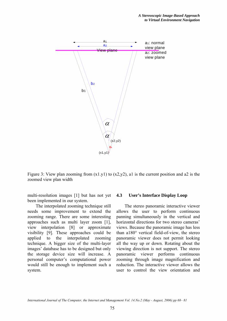
The Interpolated Zooming Technique is used to create an image sequence between the current position and the destination position. The technique is derived from the relationship between view planes of the current position and destination. Let (x1,y1) be the current position and (x2,y2) be the destination position. “a1” is the current width of the view plane at the current position (x1,y1) and a2 is the actual width of the zoomed image at the target position (x2,y2). “α” is the field of view’s angle at the user’s position. “b1” and “b2” are the angles’ edges of center view points at angle “a”. “z” is the zoom ratio of normal view plane “a1” to “a2” to make the zoom, as shown in Figure 3. It is calculated by following equations:
2
1
aaz = (1)
22 )()( yxd ∆+∆= (2)
∆x = ( x2-x1) and ∆y = (y2-y1)
⎟⎠
⎞⎜⎝
⎛= −
2ha
tan2 11α (3)
)2
tan(*))
2tan(*2
(2 1
1
αα da
az−
= (4)
The z value specifies the zooming ratio
of the original image to the destination image. The interpolated zooming will continuously zoom to the image by steps until z is satisfied and then load a new omni-directional stereo pair for the user’s new position. Another approach that can improve the quality of the zoom image is the use of
A Stereoscopic Image-Based Approach to Virtual Environment Navigation
International Journal of The Computer, the Internet and Management Vol. 14.No.2 (May - August, 2006) pp 68– 81
75
View plane
α
d
α
a2
a1
b1
b2
(x1,y1)
(x2,y2)
a1: normalview planea2: zoomedview plane
Figure 3: View plan zooming from (x1.y1) to (x2,y2), a1 is the current position and a2 is the zoomed view plan width multi-resolution images [1] but has not yet been implemented in our system.
The interpolated zooming technique still needs some improvement to extend the zooming range. There are some interesting approaches such as multi layer zoom [1], view interpolation [8] or approximate visibility [9]. These approaches could be applied to the interpolated zooming technique. A bigger size of the multi-layer images’ database has to be designed but only the storage device size will increase. A personal computer’s computational power would still be enough to implement such a system.
4.3 User’s Interface Display Loop The stereo panoramic interactive viewer
allows the user to perform continuous panning simultaneously in the vertical and horizontal directions for two stereo cameras’ views. Because the panoramic image has less than a180° vertical field-of-view, the stereo panoramic viewer does not permit looking all the way up or down. Rotating about the viewing direction is not support. The stereo panoramic viewer performs continuous zooming through image magnification and reduction. The interactive viewer allows the user to control the view orientation and

Vajirasak Vanijja and Susumu Horiguchi
76
displays correct perspective views by warping two real-time panoramic images.
All of the omni-directional binocular stereoscopic images are linked to the positions marked on the space floor in a 2D lattice using a mapping table. Currently, the linking is performed by manually registering the source and destination view orientations using the mapping table. The main goal of the registration is to maintain visual consistency when moving from one node to another adjacent node or position. The display loop will read the user’s position and load a related omni-directional binocular stereo image pair for display. The moving directions are fixed in eight directions to the adjacent positions of the 2D lattice, in the N, NW, W, SW, S, SE, E and NE directions. With no hotspots as presented in Quicktime VR [1], the user can select the next position by arrow icons when he decides the direction in which to move. The panoramic viewer will turn automatically to the selected direction and move. The display loop algorithm is shown in Figure 4.
The user can navigate around the space from one position to another where panoramic images are attached. In order to preserve continuity of motion, the view direction needs to be maintained when jumping to an adjacent location. The panoramic images are linked together by matching their orientation manually. The interpolated zooming method is applied to the jumping process to smooth the user’s view.
5. Evaluation
The evaluation takes into account the
quality of stereo matching and interpolated zooming. The stereo matching algorithm finds range data for objects in the environment. This process can prove the quality of the omni-directional stereoscopic pair. The second evaluation is the interpolated zooming quality, which
compares the last image of the zooming and the new image at the destination by image comparison algorithms.
5.1 Stereo matching
In this section, a stereo matching
algorithm is used to estimate the quality of the 360º stereoscopic images. Zitnick presented an algorithm for matching and occlusion detection [13]. The algorithm is described as follows:
1) Prepare a 3D array, (r, c, d): (r,c) for each pixel in the reference image where d is the range of disparity. The 3D disparity space has dimensions row r, column c, and disparity d. This parameterization is different from 3D volumetric methods, that use x, y, and z world coordinate as dimensions. Assuming (with loss of generality) that the images have been rectified, each element (r, c, d) of the disparity space projects to the pixel (r, c) in the left image and to the pixel (r, c+d) in the right image. Within each element, the estimated value of a match between the pixels is maintained.
2) Set initial match values L0 using a function of image intensities, such as normalized correlation or squared differences. To obtain a smooth and detailed disparity map, an iterative update function is used to refine the match values. Let ),,( dcrLn denote the match value assigned to element(r, c, d) at iteration n. The initial value ),,(0 dcrL may be computed from images LeftI and RightI using:
),,,,(),,(0 dcrIIdcrL RightLeftδ= (5)
where δ is an image similarity function

A Stereoscopic Image-Based Approach to Virtual Environment Navigation
International Journal of The Computer, the Internet and Management Vol. 14.No.2 (May - August, 2006) pp 68– 81
77
start
get the positionand view vector of
the user bytracking or pointer
device
Initial user'sPosition andview direction
Apply the interpolatedzooming from current
images to the newposition
Has usermove?
Y
YIdentify the next
position by viewingdirection
load mappingtable
B
Display thestereo images in
the specifiedviewing direction
Quit ?N
END
Y Load the new stereopanoramic imagesthat are related to
the user's newposition (identify by
mapping table)
Load thepanoramic stereo
images whichrelate to the user's
position
B
maintain theviewing direction
N
Figure 4: Display loop’s flow chart of stereo panoramic interactive viewer.
3) Iteratively update match values Ln, until the match value converges.
α)
)",","(),,(
(),,(),,(
),,("),","(
01 ∑Ψ∈
+ ∗=
dcrdcrn
nn dcrS
dcrSdcrLdcrL
(6)
Where ),,( dcrSn is the amount of local support for (r, c, d), for example, the sum of all match values within a 3D local support area Φ. ),,( dcrΨ denotes the set of elements which overlap element (r,c,d) when projected onto an image. The inhibition constant α, should be chosen to allow elements within the local support Φ to affect the match values for several iterations while also maintaining a reasonable convergence rate.

Vajirasak Vanijja and Susumu Horiguchi
78
4) For each pixel (r,c), find the element (r,c,d) with the maximum match value.
5) If the maximum match value is higher than a threshold, output the disparity d, otherwise classify it as occluded. The disparity map represents the distance of objects in the scene.
The disparity map can represent range data for stereo images. The range data shown in Figure 5 (c) show that the output 360º panoramic images have good stereoscopic characteristics. The user can perceive distance within the images. The confidence map in Figure 5 (d) displays the scene’s details that clarify the disparity map image. The output stereoscopic pair for the user’s view is displayed in Figure 6. 5.2 The Interpolated zooming evaluation
To evaluate the Interpolated Zooming
calculation, we consider the difference between the last step zoomed image and the destination image loaded at the end of zooming (See Figure 7). Root-Mean-Square (RMS) and Signal to Noise Ratio (SNRRMS) error calculations are used to compare the two images[14].
In this experiment, we captured images within a constrained space and in various directions. The output images from the interpolated zooming technique are compared to the images at the destination positions at each point from 0 to 1.0 m. The graph in Figure 8 shows the relationship between the average error ratio, RMS and SNR, and the distance applied to the interpolated zooming technique:
),(),('),( crIcrIcrerror −= (7)
where ),( crI is the real image taken at
the destination position and ),(' crI is the last step zoomed image from the interpolated zooming . The total error in an NxN image is
Total error = ∑∑−
=
−
=
−1
0
1
0
2)],(),('[N
r
N
ccrIcrI (8)
The root-mean-square error is found by taking the square root of the squared error divided by the total number of pixels in the image:
∑∑−
=
−
=
−=1
0
1
0
2)],(),('[1 N
r
N
cRMS crIcrI
Ne (9)
Smaller values of this metric mean
better output images with respect to the original images. Conversely, with the signal-to-noise (SNR) metric, a larger number implies a better image. The SNR metric considers the output image ),(' crI to be the “signal” and the error to be “noise”. We can define the ratio as:
∑∑
∑∑−
=
−
=
−
=
−
=
−= 1
0
1
0
2
1
0
1
0
2
)],(),('[
)],('[
N
r
N
c
N
r
N
cRMS
crIcrI
crISNR
(10)
From Figure 8, the RMS error is
increased and SNR is decreased as the zooming distance increases. At 1 meter, the RMS error is over 50, which implies a large discrepancy in the synthesized image.
In this experiment, all images data were captured indoors. The limited space and closeness of objects always causes large image matching errors for interpolate zooming. The interpolated zooming technique is not recommended for use with distances larger than 1 meter for indoor or limited-space environments. For outdoor scenes with long-range objects such as a scenic view or a driving tour taken from a moving car, this technique is effective for longer distances but we require further experimentation to determine the system’s limitations.

A Stereoscopic Image-Based Approach to Virtual Environment Navigation
International Journal of The Computer, the Internet and Management Vol. 14.No.2 (May - August, 2006) pp 68– 81
79
Figure 5: 360º stereoscopic images and disparity map images, a) and b) 360º panoramic
image for right eye and left eye, c) disparity map of a) and b), d) confidence map of a) and b).
Figure 6: A cropped images for the user’s view. a) and b) are the cropped image for the
left eye and the right eye respectively.
a) b) Figure 7: Comparison images at z = 0.7m. : a) the image from the zooming b) the
destination image

Vajirasak Vanijja and Susumu Horiguchi
80
0
10
20
30
40
50
60
0 0.25 0.5 0.75 1
Distance (m)
Erro
r rat
io
SNR_AVG RMS_AVG
Figure 8: Error estimation of the interpolation zooming technique as a distance function from 0m to 1m. SNR_AVG is average value of Signal to Noise Raito and RMS_AVG is average of Root Mean Square error. 6. Conclusion and Future work
The omni-directional binocular
stereoscopic images can improve the navigation efficiency because the user can feel distance within the environment. The method proposed here for producing the omni-directional binocular stereoscopic images is more convenient than previous approaches because fewer photos are taken at any position so multi-position capturing processes are easier and faster. An omni-directional sensor called “ PAL”, which can be used with a digital still camera, also makes our approach easier to implement. The method’s limitations are the requirements that the scenes are static and that movement is confined to particular points. Time-varying environment maps or merging 3D synthesized objects into the environment maps can solve the first limitation. The second limitation is still difficult to solve but the method in this paper allows the user to smoothly navigate around the virtual environment with eight directions of freedom.
Recently, stereo image-based virtual environment navigating systems have been designed for use on personal computers. The prototype system has been implemented and tested on a PC with an Intel Pentium III 800 MHz and 256 MB of memory. The largest display image size is 640*480 pixels for each eye. With a dual head display card, the user can immerse into the virtual environment with Head Mount Display. Otherwise, the single position approach of omni-directional binocular stereoscopic images can be applied to many applications using stereoscopic display techniques such as anaglyphs or field-sequential techniques with a shutter glasses.
The final resolution for the omni-directional binocular stereoscopic image is 5200*850 pixels (the original circular images contain 2 million pixels which are taken by a digital still camera with an omni-directional lens called “PAL”). With this resolution, the image can be implemented on a large display system such as CAVE or other large stereoscopic display. The display loop would have to be adapted to such systems and a

A Stereoscopic Image-Based Approach to Virtual Environment Navigation
International Journal of The Computer, the Internet and Management Vol. 14.No.2 (May - August, 2006) pp 68– 81
81
new user’s interface design would have to be implemented for use with a 3D tracking device.
The ultimate goal of virtual reality is a simulation of the real world in which nobody can recognize the artificiality of the scene. Our approach with stereoscopic sense for the user may be another step closer to the goal.
Reference
[1] S. E. Chen, “QuickTime VR: an image-based approach to virtual environment navigation”, Proceedings of the 22nd annual ACM conference on Computer graphics, 1995, 29 – 38.
[2] S. K. Nayar, T. Boult, “Omnidirectional Vision Systems: 1998 PI Report”, Department of Computer Science Department of EE and CS Columbia University Lehigh University New York, N.Y. 10027 Bethlehem, PA 18015
[3] S. K. Nayar, “Omnidirectional Vision”, The Eighth International Symposium of Robotics Research, Hayama, Japan, October3-7, 1997
[4] V. N. Peri and S.e K. Nayar, “Generation of Perspective Panoramic Video from Omnidirection Video”, Proc. of DARPA Image Understanding Workshop, New Orleans, May 1997
[5] Y. Onoe, K. Yamazawa, H. Takemura, and Naokazu Yokoya, “Telepresence by real-time view-dependent image generation from omnidirectional video streams”, Computer Vision and Image Understanding 1998, Vol.71, No.2, 154-165
[6] D.G. Aliaga, I. Carlbom, “Plenoptic stitching: A scalable method for reconstructing 3D interactive walkthroughs”, Proc. ACM SIGGRAPH 2001(2001), 443-450.
[7] V.Vajijja and S.Horiguchi, “360° Interactive Video Scenes with Multi-
directional Moving Capability”, Proc. ICAT2001, pp.209-212.
[8] S. Kang and R. Szelisky. “3-D scene data recovery using omnidirectional multibaseline stereo”. In IEEE Conference on Computer Vision and Pattern Recognition, June 1996, 364– 370.
[9] H.-C. Huang and Y.-P. Hung, “Panoramic stereo imaging system with automatic disparity warping and seaming”,. Graphical Models and Image Processing, , May 1998, 60(3):196–208.
[10] S.Peleg, M. Ben-Ezra, and Yeal Pritch, “Ommistereo: Panoramic Stereo Imaging”, IEEE Transsction on pattern analysis any machine intelligence, March 2001, VOL 23, No.23, 279-290.
[11] K. Yamaguchi, H. Takemura, K. Yamazawa, N.Yokoya, “Real-time Generation and Presentation of View-dependent Binocular Stereo Images Using a Sequence of Omnidirectional images”, Proc. 15th ICPR, 2000, Vol.4, 482-486
[12] R. Szeliski, “Video Mosaics for Virtual Environments”, IEEE Computer Graphics and Applications, March 1996,Vol. 16, No. 2, pp. 22-30
[13] C. Lawrence Zitnick and Takeo Kanade, “A Cooperative Algorithm for Stereo Matching and Occlusion Detection”, IEEE Transactions on pattern analysis and machine intelligence, 2000, Vol. 22, No.7
[14] Umbaugh, Scott E., Computer vision and image processing: a practical approach using CVIPtools, Prentice Hall PTR 1998.