a study of boundaries and transiti ons: a nature … · w30x90 w30x90 w14x34 ... while this beam is...
TRANSCRIPT

A Study of Boundaries and Transiti ons: A Nature Center in West Virginiaby
ANNIKA MARIE PLEVICH
Thesis submi ed to the faculty of Virginia Polytechnic Insti tute and State University in parti al fulfi llment of the requirements for the degree of
MASTER OF ARCHITECTURE
HANS ROTT, Commi ee ChairJAMES JONES, Commi ee Member
HEINRICH SCHNOEDT, Commi ee MemberSTEVE THOMPSON, Program Chair
May 4th, 2009Blacksburg, Virginia

A Study of Boundaries and Transiti ons: A Nature Center in West Virginia
ANNIKA MARIE PLEVICH
ABSTRACT
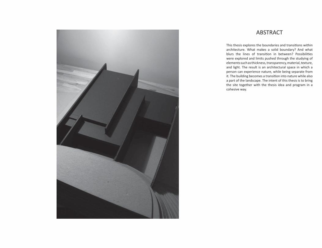
This thesis explores the boundaries and transiti ons within architecture. What makes a solid boundary? And what blurs the lines of transiti on in between? Possibiliti es were explored and limits pushed through the studying of elements such as thickness, transparency, material, texture, and light. The result is an architectural space in which a person can experience nature, while being separate from it. The building becomes a transiti on into nature while also a part of the landscape. The intent of this thesis is to bring the site together with the thesis idea and program in a cohesive way.

ACKNOWLEDGMENTS
iii
I would like to thank all of my professors at Virginia Tech for your guidance and encouragement. Especially, I would like to express my sincere grati tude to my graduate commi ee members; Hans, Jim, and Heiner, who I have had the honor of working with this past year. Thank you for inspiring me to achieve my goals and for your conti nuing confi dence in me; for keeping me on my toes and being able to see potenti al in my rough sketches. Also thanks to Steve Thompson, for being an outstanding chair for the graduate program and advisor to all of us. To Mehdi Setareh for being a mentor to me, advising me about my future, and for his help with my thesis.A special thanks to my family. To my mother for her faith in me. To my father for his enthusiasm and moti vati on. To both of my parents for giving me a love for nature, and for always believing in me and helping me to pursue my dreams.And to my sister, Eva, for always being there for me, especially in the weak moments. Thank you for your kind words and for always keeping me going!Finally, I would like to thank those in my studio. I owe a special thanks to Emily, Luke, Mandy, Jon, Jared, Imrbie, Kristen, and Taylor. To those who sat nearby my desk; for your inspirati ons, ideas, and friendship. Thanks to the late night crew for keeping me company and keeping me sane, to those who tolerated my loudness during studio, and to all of my friends at Virginia Tech for making my experience here so memorable.

Acknowledgements
Introducti onThesisProgramSite
Boundaries
Transiti ons
Conclusion, Final DrawingsBibliography
iii
1234
7
16
2640
CONTENTS
iv

1
INTRODUCTION
This thesis is a propositi on for a nature center through the studies of boundaries and transiti ons. The idea of a nature center is a place for people to learn about their surroundings. It acts as a bridge between two worlds; the human- developed world, and the unbuilt world. Because of the already existi ng boundary between these two extremes, maintaining a solid boundary was important to the architectural propositi on. Boundaries can be a part of architecture by limiti ng access or sight, or drawing defi nite lines separati ng two things. In contrast, a blurred transiti on also became part of the propositi on. Transiti ons can be a part of architecture by merging two or more diff erent things. This intenti on, combined with the program, created a compromise between man and nature; a place where one can appreciate and be educated on nature.
2
THESIS
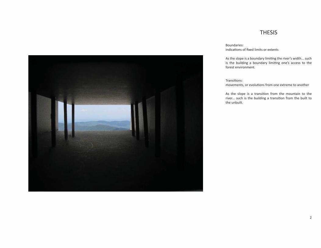
Boundaries:indicati ons of fi xed limits or extents
As the slope is a boundary limiti ng the river’s width... such is the building a boundary limiti ng one’s access to the forest environment.
Transiti ons:movements, or evoluti ons from one extreme to another
As the slope is a transiti on from the mountain to the river... such is the building a transiti on from the built to the unbuilt.

3
PROGRAM
Understanding and appreciati ng nature is absolutely crucial to our future. Society must learn to exist peacefully and respec ully with nature without destroying it. The program of this thesis is a Nature Center in north-central West Virginia. Because West Virginia is a state vastly covered in forest, it is also an opti mal place in which to experience the natural surroundings. This nature center would hopefully serve as a transiti onal building into the unbuilt environment.
Mezzanine Floor Plan
Ground Floor Plan
Mezzanine Exhibit Area
Main Exhibit Area
Offi ce
Courtyard Conference/ Event Room
StorageBathrooms
Terrace Area
Elevator
Gi Shop
Stairs/ Elevator to Mezzanine
Entrance
4
SITE
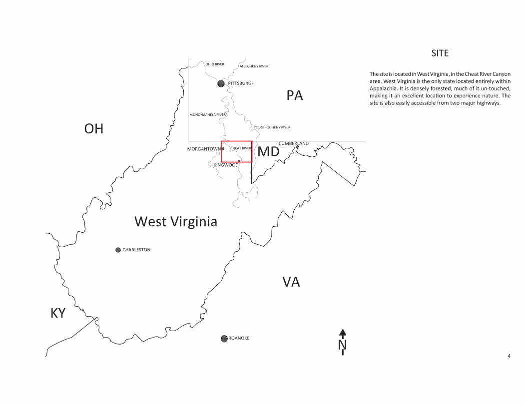
The site is located in West Virginia, in the Cheat River Canyon area. West Virginia is the only state located enti rely within Appalachia. It is densely forested, much of it un-touched, making it an excellent locati on to experience nature. The site is also easily accessible from two major highways.

5
SITE
The Cheat River Canyon is located in North-central West Virginia and extends between the towns of Albright and Morgantown. Just outside of Morgantown, it forms Cheat Lake. The canyon runs for the full ten miles between the two towns. The Cheat River a racts many because of its whitewater. It is a desti nati on for many ra ers and kayakers, with its class IV and V rapids. It is said that the Cheat River’s name originated from the white water where it has cheated many people out of their lives.The diff erence in elevati on from the river to the canyon’s rim is as much as 1,200 feet in some areas. This gives a spectacular view from the top, and a prime locati on for the building site. A er fl owing out of Cheat Lake, the river then joins with the Monongahela River north of Morgantown. The Monongahela River eventually joins with the Ohio River in Pi sburgh, which is a part of the Mississippi River watershed.

6
SITE
The building site is located along the rim of the canyon, south of Big Sandy Creek and Conner Run. While the existi ng contours are quite steep, they were pushed back further and ever more steeply to make space for the building and provide a dramati c slope.
Contours are 100 increments
Secti on of Canyonat locati on of site
0 2000

7
BOUNDARIES
8
WALLS IN PLAN
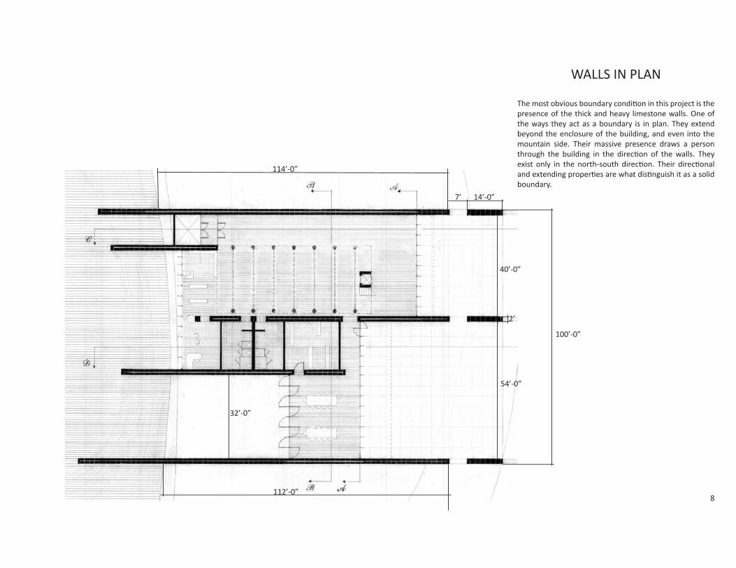
The most obvious boundary conditi on in this project is the presence of the thick and heavy limestone walls. One of the ways they act as a boundary is in plan. They extend beyond the enclosure of the building, and even into the mountain side. Their massive presence draws a person through the building in the directi on of the walls. They exist only in the north-south directi on. Their directi onal and extending properti es are what disti nguish it as a solid boundary.
114’-0”
32’-0”
112’-0”
40’-0”
54’-0”
100’-0”
7’ 14’-0”
2’
9
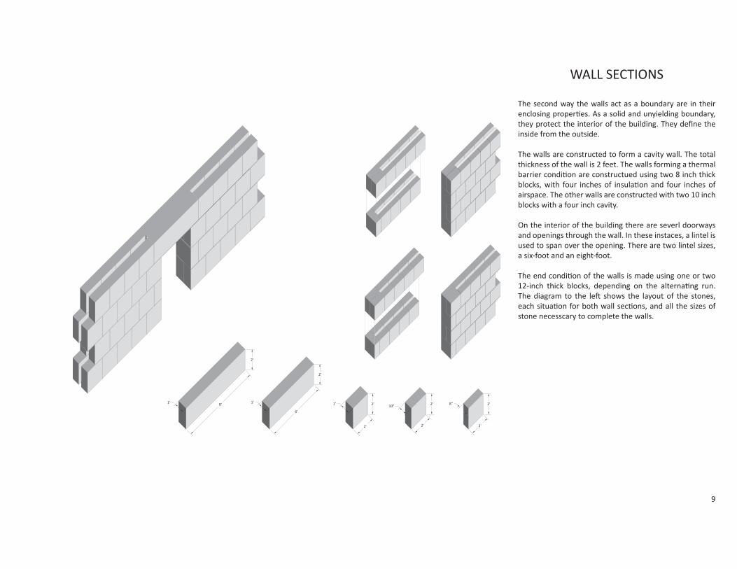
WALL SECTIONS
The second way the walls act as a boundary are in their enclosing properti es. As a solid and unyielding boundary, they protect the interior of the building. They defi ne the inside from the outside.
The walls are constructed to form a cavity wall. The total thickness of the wall is 2 feet. The walls forming a thermal barrier conditi on are constructued using two 8 inch thick blocks, with four inches of insulati on and four inches of airspace. The other walls are constructed with two 10 inch blocks with a four inch cavity.
On the interior of the building there are severl doorways and openings through the wall. In these instaces, a lintel is used to span over the opening. There are two lintel sizes, a six-foot and an eight-foot.
The end conditi on of the walls is made using one or two 12-inch thick blocks, depending on the alternati ng run. The diagram to the le shows the layout of the stones, each situati on for both wall secti ons, and all the sizes of stone necesscary to complete the walls.

10
TERRAIN
Along the gradually rising mountain side, an area where the countours become . The steep slope creates a “wall”. Its presence is especially known in the courtyard area, where the steep terrain creates a courtyard between the two walls.

11
ROOF
The roof acts as a boundary between the inside and the outside of the building, horizontally. The walls extend verti cally beyond their boundary. The roof of the building is at two heights. In the main part of the building, the roof is a height of 26 feet. This allows for the mezzanine level, and also a dramati c ceiling height. The ceiling under the mezzanine is 12 feet, and the roof in the wing of the building is 16 feet high. The changing ceiling heights defi nes the diff erent areas of the building. The roof is also secondary to the walls, as they extend beyond the limit of the roof.
12
Main Area
Wing
W30x90
W30x90
W14x34
W14x34
W14x34
44LH09 9 at 4’-0”
20LH02 17 at 3’-0”
44LH09 9 at 3’-0”
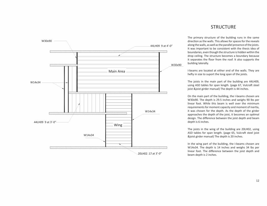
STRUCTURE
The primary structure of the building runs in the same directi on as the walls. This allows for spaces for the reveals along the walls, as well as the parallel presence of the joists. It was important to be consistent with the thesis idea of boundaries, even though the structure is hidden within the drop ceiling. The structure becomes a boundary because it separates the fl oor from the roof. It also supports the building laterally.
I-beams are located at either end of the walls. They are he y in size to suport the long span of the joists.
The joists in the main part of the building are 44LH09, using ASD tables for span length. (page 67, Vulcra steel joist &joist girder manual) The depth is 44 inches.
On the main part of the building, the I-beams chosen are W30x90. The depth is 29.5 inches and weighs 90 lbs per linear foot. While this beam is well over the minimum requirements for moment capacity and moment of inerti a, it was chosen for the depth. As the depth of the girder approaches the depth of the joist, it becomes an opti mal design. The diff erence between the joist depth and beam depth is 6 inches.
The joists in the wing of the building are 20LH02, using ASD tables for span length. (page 65, Vulcra steel joist &joist girder manual) The depth is 20 inches.
In the wing part of the building, the I-beams chosen are W14x34. The depth is 14 inches and weighs 34 lbs per linear foot. The diff erence between the joist depth and beam depth is 2 inches.

13
STRUCTURE
The remaining porti on of the building’s structure uses 20LH02 joists for consistency, since it is at the same roof height of the wing secti on. The joists span between the walls, since these walls are not lit by the reveals of the roof. Two W14x34 beams span in the longest area in the offi ce space.
The steel girders are connected to the load bearing limestone cavity walls by using steel angles and anchor bolts. The area where the girders are bolted are also fi lled with concrete within the cavity space. This causes the wall to act as a column at these locati ons.
The structures supports the boundary conditi on simply by its nature of protecti ng and holding up the building.
W14x34
20LH02 joist
Concrete fi ll
Steel bolts Ceiling
8” limestone blocks
Glass
L-angleInsulati on
20LH02 joist
W14x34Steel Plate
44LH09 joist
Steel hangers
Drop glass panel ceilingGlass
W30x90
Limestone
Insulati on1” Steel deck
14
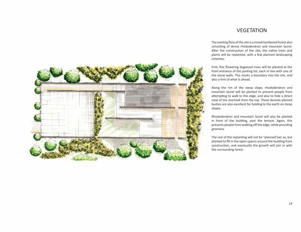
VEGETATION
The existi ng fl ora of the site is a mixed hardwood forest also consisti ng of dense rhododendron and mountain laurel. A er the constructi on of the site, the nati ve trees and plants will be replanted, with a few planned landscaping schemes;
First, fi ve fl owering dogwood trees will be planted at the front entrance of the parking lot; each in line with one of the stone walls. This marks a boundary into the site, and also a hint of what is ahead.
Along the rim of the steep slope, rhododendron and mountain laurel will be planted to prevent people from a empti ng to walk to the edge, and also to hide a direct view of the overlook from the top. These densely planted bushes are also excellent for holding to the earth on steep slopes.
Rhododendron and mountain laurel will also be planted in front of the building, past the terrace. Again, this prevents people from walking off the edge, while providing greenery.
The rest of the replanti ng will not be “planned”per se, but planted to fi ll in the open spaces around the building from constructi on, and eventually the growth will join in with the surrounding forest.

15
MEZZANINE
The building site not only has boundaries in the horizontal directi on, but also in the verti cal. Within the building, the mezzanine acts as a boundary within the larger space. The columns supporti ng it provide a boundary and signify what is above.

16
TRANSITIONS

17
WALLS
The walls of the building are also a part of the transiti on. Because their origin is within the side of the mountain, they are a part of the landscape as they emerge from the steep terrian. The walls become an extension of the landscape.

18
WALLS - REVEALS
The conditi ons of light were studied in the building. Because the depth of the roof is almost four feet, the width of the reveal needed to be studied for the ulti mum eff ect. Of the varius widths tested, the six inch reveal provided a light wash while also bringing out the texture of the wall. The light spilling from the reveal draws the eye upward. It not olnly gives the walls more presence, but it also gives a transiti on between the outside and the inside. The light helps to blend the transiti on verti cally- blurring the height of the wall with the sky.
6 inch4 inch2 inch1 inch 12 inch
6 inch reveal- fi nal choice

19
WALLS - JOINTSThe joints in the walls between the stones are of two diff erent depths. The verti cal depth is 1/8 of an inch, and the horizontal is 1/2 inch. When the light spills over the wall from the reveals in the roof, it creates dramati c shadows along the horizontal joints. Upon entering the building from the elevator, this would be very obvious. The joint shadows would draw your eye toward the opening on the opposite side of the building, toward the outside. The wall acts to carry you in transiti on from the inside to the outside.

20
APPROACH- PARKING LOT
The fi rst planned element of the site is the parking lot. The fi rst thing one would approach are the fi ve trees, marking the fi ve massive walls on the other side of the hill. The next element is the pavement of the parking lot. Between each paver is earth, allowing grass to grow between. This is an even more slight transiti on into the built world. On the side of the parking lot, is a sidewalk and ramp, which directs one toward the entrance of the building.
21
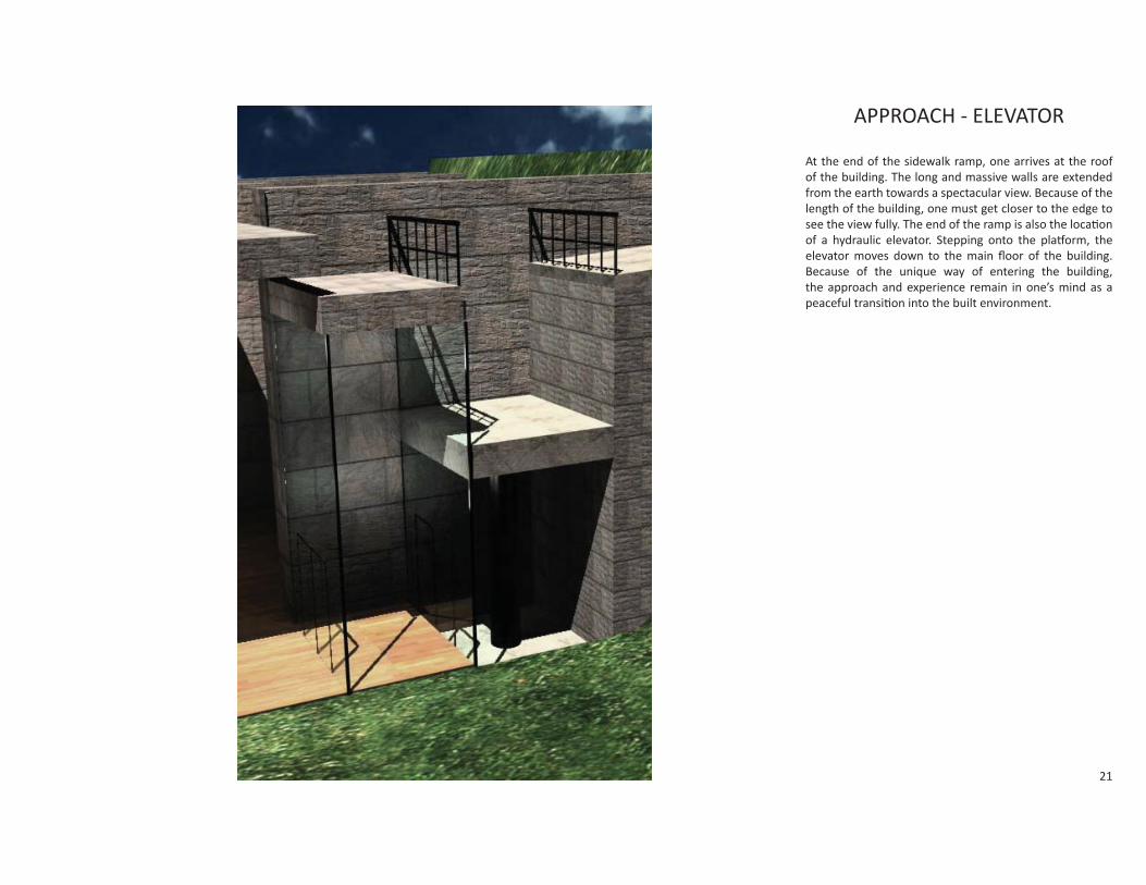
APPROACH - ELEVATOR
At the end of the sidewalk ramp, one arrives at the roof of the building. The long and massive walls are extended from the earth towards a spectacular view. Because of the length of the building, one must get closer to the edge to see the view fully. The end of the ramp is also the locati on of a hydraulic elevator. Stepping onto the pla orm, the elevator moves down to the main fl oor of the building. Because of the unique way of entering the building, the approach and experience remain in one’s mind as a peaceful transiti on into the built environment.

22
WINDOW CONDITIONS
The windows in the building are constructed using glass mullions. This makes the transiti on from inside to outside as smooth as possible, as the presence of the glass almost disappears. The only thing one sees when looking out is the breathtaking scenery. This is opposed to framed traditi onal window mullions.
23
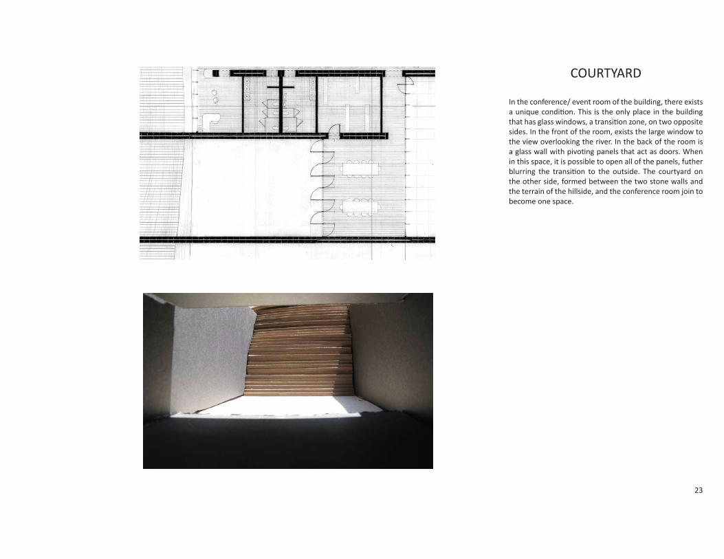
COURTYARD
In the conference/ event room of the building, there exists a unique conditi on. This is the only place in the building that has glass windows, a transiti on zone, on two opposite sides. In the front of the room, exists the large window to the view overlooking the river. In the back of the room is a glass wall with pivoti ng panels that act as doors. When in this space, it is possible to open all of the panels, futher blurring the transiti on to the outside. The courtyard on the other side, formed between the two stone walls and the terrain of the hillside, and the conference room join to become one space.

24
CEILING
The eff ect of the building at night is quite diff erent from during the day, with a lack of light. The reveals do not light up the walls, and the light from outside does not provide a picture frame for the eye to follow. The internal parts of the building must play its part in transiti ons.
The ceiling is a drop system made of thin frosted glass. It is lit from inside the ceiling and creates a transluscent glow. The eff ect is a fl oati ng and glowing ceiling. The mezzanine fl oor is also lit this way. This contrasts greatly with the building’s massive walls, which appear especially heavy and dark at night.
Lights Glass panels
Hangers

25
A PLACE FOR SITTING
The fi nal transiti on from the built to the unbuilt lies in the outdoor area on the terrace. The walls are extended a er a small break of seven feet. The extensions are a height of 30 inches; perfect for climbing to sit on and enjoying the view. The extensions are a transiti on of the wall’s disappearance into the wild. They are also a transiti on of the presence of the walls from being a massive presence to becoming something at the human scale. One can sit on, climb over and look across the lower walls and see what the nature center is all about; the breathtaking landscape and sceneary of West Virginia.
26
CONCLUSION: THE FINAL DRAWINGS

27
LOCATION
0 1000500200
Contours are 20 foot increments

28
SITE PLAN AND ELEVATIONS

29
SITE PLAN AND ELEVATIONSDIMENSIONS
100’-0”100’-0”
139’-0”
134’-0”
96’-0”
30
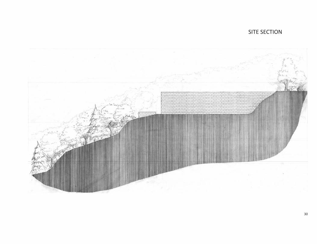
SITE SECTION

31
SITE SECTIONDIMENSIONS
134’-0”
14’-0”

32
GROUND FLOOR PLAN

33
GROUND FLOOR PLANDIMENSIONS
114’-0”
134’-0”
32’-0”
112’-0”138’-0”
40’-0”
54’-0”
100’-0”
7’ 14’-0”
2’

34
MEZZANINE FLOOR PLAN

35
MEZZANINE FLOOR PLANDIMENSIONS
58’-0”12’-0”
26’-0”
1’-0”

36
NORTH-SOUTH SECTIONS

37
NORTH-SOUTH SECTIONSDIMENSIONS
125’-0”82’-0”
28’-0”
14’-0”
129’-0”84’-0”
28’-0”
14’-0”
23’-0”

38
EAST-WEST SECTIONS

39
EAST-WEST SECTIONSDIMENSIONS
19’-0”
28’-0”22’
26’-0”
11’-0”16’-0”
33’-0” 40’-0”
28’-0”
2’9’-0”
54’-0” 40’-0”
8’-8”
2’

40
BIBLIOGRAPHY
All photos, images, drawings, renderings, and scans by author.