a study of electromagnetic absorbers and cloaks for …
TRANSCRIPT

The Pennsylvania State University
The Graduate School
Department Electrical Engineering
A STUDY OF ELECTROMAGNETIC ABSORBERS AND CLOAKS
FOR THE REDUCTION OF ELECTROMAGNETIC SCATTERING
A Dissertation in
Electrical Engineering
by
Yuda Zhou
2015 Yuda Zhou
Submitted in Partial Fulfillment
of the Requirements
for the Degree of
Doctor of Philosophy
August 2015

The dissertation of Yuda Zhou was reviewed and approved* by the following:
Raj Mittra
Professor of Electrical Engineering
Dissertation Advisor
Co-Chair of Committee
Julio Urbina
Professor of Electrical Engineering
Co-Chair of Committee
Ram Narayanan
Professor of Electrical Engineering
Michael Lanagan
Professor of Engineering Science and Mechanics
Kultegin Aydin
Professor of Electrical Engineering
Head of the Department of Electrical Engineering
*Signatures are on file in the Graduate School

iii
ABSTRACT
Electromagnetic absorbers and scattering reduction techniques have long been
investigated to discover better performing configurations and exploited to reduce Radar Cross-
Section, act as sensors or reduce obstruction effects, throughout the electromagnetic spectrum
ranging from UHF to terahertz frequencies, and even at infrared and optical wavelengths.
This dissertation presents the research on a novel interpretation and design strategy for
designing absorbers based on periodic structures and introduces an algorithm for determining the
optimal material parameter for layered absorbers that are wrapped around real-world objects with
structural perturbations from a planar surface, which traditional research focuses on almost
exclusively. A brief history of absorbers was given and legacy configurations of absorbers were
introduced in the first place. Secondly, novel Frequency Selective Surface (FSS)-based absorbers
were proposed based on the interpretation of the reciprocity theorem for antenna systems. FSS-
based absorbers and were incorporate into layered absorbers as composites for tailored absorption
specifications. A comparison of performances was given to serve as a general rule of thumb to
select optimal configuration for tailored specifications. This dissertation investigates a nascent
solution to the scattering reduction problem, namely cloaking based on the physics of
Transformation Optics (TO) and presents the real-world limitations of such solutions. This
dissertation proposes an alternative algorithm for developing the optimal material parameter for a
physical object in a real-world scenario.
These explorations show the great promise and applicability of a comprehensive tailored
absorber design strategy on a case-by-case basis.

iv
TABLE OF CONTENTS
List of Figures .......................................................................................................................... vi
List of Tables ........................................................................................................................... x
Acknowledgements .................................................................................................................. xi
Chapter 1 Overview ................................................................................................................. 1
1.1 Dissertation Outline ................................................................................................... 1 1.2 Notations and Symbols .............................................................................................. 2
Chapter 2 Traditional Electromagnetic Absorbers ................................................................... 3
2.1 Introduction ................................................................................................................ 3 2.2 Salisbury Screen Absorber ......................................................................................... 4 2.3 Dallenbach Layer Absorber ....................................................................................... 8 2.4 Jaumann Absorber ...................................................................................................... 11 2.5 Summary .................................................................................................................... 13
Chapter 3 Frequency Selective Surface (FSS)-based Absorber for Wideband Applications .. 15
3.1 Introduction ................................................................................................................ 15 3.2 General Reciprocity Theorem .................................................................................... 16 3.3 Reciprocity Theorem for Antenna Systems ............................................................... 17 3.4 Unit–Cell Design and Bandwidth Expansion............................................................. 18 3.5 Wideband Unit-Cells and Dual-Direction Capabilities .............................................. 20 3.6 Lossy FSS Analysis ................................................................................................... 22
Chapter 4 Multi-Layered Absorber for Ultra Wideband Applications .................................... 28
4.1 Design of Multilayered Absorber ............................................................................... 28 4.1.1 Reflection Coefficient for obliquely incident stratified isotropic dielectric
layers with a PEC ground plane ....................................................................... 28 4.1.2 Optimization Process for Maximizing Frequency Bandwidth and
Minimizing Thickness ...................................................................................... 32 4.2 RCS Reduction for Test Targets ................................................................................ 35 4.3 FSS and Multi-Layered Composite Absorber for Performance Enhancement .......... 37
4.3.1 Target Band Absorption Enhancement ........................................................... 37 4.3.2 Thickness Reduction ....................................................................................... 38
4.4 Summary .................................................................................................................... 39
Chapter 5 Cloaking and Scattering Reduction ......................................................................... 41

v
5.1 Introduction ................................................................................................................ 41 5.2 Fundamentals of Transformation Optics .................................................................... 42 5.3 Field Transformation in the context of Generalized Scattering Matrix Approach ..... 52
Chapter 6 Scattering Reduction for Real-World Targets ......................................................... 60
6.1 Field Transformation Algorithm, Material Modification ........................................... 66 6.2 Field Transformation Algorithm, Thickness Modification ........................................ 70 6.3 Practical Applications ................................................................................................ 76
Chapter 7 Suggestions for Future Works ................................................................................. 80
Bibliography..................................................................................................................... 82

vi
LIST OF FIGURES
Figure.2.1. Schematics for the Salisbury screen. ..................................................................... 4
Figure.2.2. Wave interactions in different mediums of the Salisbury screen. ......................... 5
Figure.2.3. Reflection coefficients for designed Salisbury screen with different sheet
resistances. ....................................................................................................................... 6
Figure.2.4. Reflection coefficients for designed Salisbury screen with spacers of different
dielectric constants and corresponding thicknesses. ........................................................ 8
Figure.2.5. Schematics for the Dallenbach Layer Absorber. ................................................... 9
Figure.2.6. Microwave absorption properties of the FePc–Fe3O4–BF/BPh/FePc–Fe3O4
composite laminates. ........................................................................................................ 10
Figure.2.7. Electromagnetic properties of composite laminates: (a) real part of
permittivity, (b) real part of permeability, (c) imaginary part of permittivity, (d)
imaginary part of permeability. ........................................................................................ 11
Figure.2.8. Schematics for an 8-layer Jaumann absorber. ....................................................... 13
Figure.2.9. Reflection coefficient for an 8-layer Jaumann absorber. ....................................... 13
Figure.3.1. Transmitting and receiving antenna systems. ........................................................ 17
Figure.3.2. Two-antenna system with conjugate loads. ........................................................... 17
Figure.3.3. (a,d) Isometric; (b,e) top; and (c,f) side view of the cross-strip model with
inter-connected resistors (red) and duo layer stack model, respectively (D=15,
W=12, H=5.5, H’=11.5 unit: mm). .................................................................................. 19
Figure.3.4. (a,d) Isometric; (b,e) top; and (c,f) side view of the cross-strip model with
inter-connected resistors (red) and duo layer stack model, respectively (D=15,
W=12, H=5.5, H’=11.5 unit: mm). .................................................................................. 20
Figure.3.5. Illustration of the (a) isometric; (b) top; (c) side view of the 3-layer bowtie
absorber model and the (d) 1st layer; (e) 2nd layer; (f) 3rd layer (L=53.4mm,
W=21mm, d=6mm). ......................................................................................................... 21
Figure.3.6. Reflection, transmission and absorption coefficient of the three layer
absorber-screen model. .................................................................................................... 21
Figure.3.7. Schematics of the unit cell of an EM absorber based on dual-loop periodic
screens, model (a). ........................................................................................................... 23
Figure.3.8. Reflected power level for the original dual-loop absorber. ................................... 24
vii
Figure.3.9. Schematics of the unit cell of a modified EM absorber utilizing lossy,
complex dual-loop periodic screens, model (b). .............................................................. 25
Figure.3.10. Schematics of the unit cell of a modified EM absorber based on lossy, dual-
loop periodic screens without segmentation, model (c). .................................................. 25
Figure.3.11. Reflected power level for model (b) with varying sheet resistance. .................... 26
Figure.3.12. Reflected power level for model (c) with varying sheet resistance. .................... 27
Figure.4.1. (a) TE and (b) TM wave incident obliquely on a multi-layer dielectric with a
PEC ground plane. ........................................................................................................... 29
Figure.4.2. Model schematics of the optimization problem for the multilayer absorber. ........ 33
Figure.4.3. Real and imaginary parts of the (a) permittivity and (b) permeability for the
two types of absorbing materials used in the multi-layer absorbing blanket design. ....... 34
Figure.4.4. Reflection coefficient of multilayer absorber backed by a PEC plate for
different number of layers. ............................................................................................... 35
Figure.4.5. Back-scattering RCS of PEC objects: (a) plate, (b) pyramid, and (c) cylinder
covered with 2 and 7-layer absorbers. .............................................................................. 36
Figure.4.6. Illustration of the (a) isometric and (b) side view of the absorber cross-strip
composite model. ............................................................................................................. 37
Figure.4.7. Reflection coefficient of the absorber-screen composite model. ........................... 37
Figure.4.8. (a) Illustration of the broadband antenna; (b) S11 of the broadband antenna. ...... 38
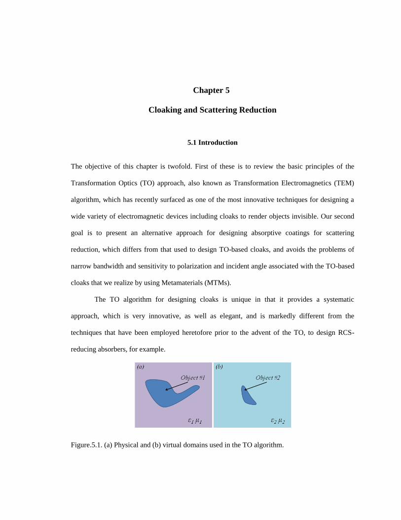
Figure.4.9. Illustration of the (a) isometric view and (b) top view of the absorber-screen
composite model. ............................................................................................................. 39
Figure.4.10. Reflection coefficient of the absorber-screen composite model. ......................... 39
Figure.5.1. (a) Physical and (b) virtual domains used in the TO algorithm. ............................ 41
Figure.5.2. (a) Schematics for a cloaked PEC cylinder with R2 = 2R1, (b) material
parameters for an all-angle, all-polarization cloak, (c) material parameters for a
normal-incident, TE-polarization cloak from [37]. .......................................................... 44
Figure.5.3 TO-based cloak schematics and corresponding materials in the (a) physical
geometry and (b) virtual geometry. .................................................................................. 46
Figure.5.4 Cloak problem with mesh schematics: (a) physical and (b) virtual domains. ........ 47
Figure.5.5 Cloak problem with mesh schematics: (a) physical and (b) virtual domains. ........ 50

viii
Figure.5.6 Field distribution for A PEC cylinder in (a) an ideal TO cloak, (b) an ideal,
thin TO cloak, (c) a 3-layered TO cloak in which the medium parameters at each
layer correspond to those of the ideal thin cloak. ............................................................. 52
Figure.5.7 Generalized Scattering Matrix (GSM) approach in the context of the Field
Transformation (FT) method............................................................................................ 54
Figure.5.8 Scattering from an arbitrarily shaped target described in the context of
Generalized Scattering Matrix (GSM) method in the physical domain (a) and virtual
domain (b). ....................................................................................................................... 57
Figure.5.9 Scattering from an FT-treated arbitrarily shaped target described in the context
of Generalized Scattering Matrix (GSM) method. ........................................................... 59
Figure.6.1 Back-scattering RCS of PEC objects: (a) plate, (b) pyramid, and (c) cylinder
covered with 2 and 7-layer absorbers. .............................................................................. 61
Figure.6.2 Phase behavior of the E-field near the rectangular PEC cylinder, which is
wrapped around by an absorber blanket, normally incident on the cylinder. .................. 62
Figure.6.3 Phase behavior of the E-field near the rectangular PEC cylinder, which is
wrapped around by an absorber blanket, for an obliquely incident plane wave. ............. 63
Figure.6.4 Target detection in conventional radar scenarios: mono-static and bi-static
scheme [39]. ..................................................................................................................... 64
Figure.6.5 (a) Original 2-layer absorber wrapped around a rectangular cylinder with
shape perturbation (left); (b) 2-layer absorber with TO-modified material properties
around regions with the shape perturbation (left); (c) 2-layer absorber with TO
modified material properties for all regions (left) and 2-layer absorber wrapped
around a rectangular cylinder (right). ............................................................................... 66
Figure.6.6 Phase behavior of scattered E-field for (a) perturbed object wrapped by
blanket with original medium parameter; (b) perturbed object wrapped by blanket
with locally modified medium parameter. ....................................................................... 68
Figure.6.7 Comparison of the amplitudes of electric fields scattered by different objects. ..... 68
Figure.6.8 Possible domain decomposition of two aircrafts: F-16 Falcon fighter jet (left)
and Predator Drone UAV (right) for scattering-reduction treatment. .............................. 69
Figure.6.9 Comparison of bi-static RCS for a long PEC cylinder coated with absorbers
with various thickness compositions, for horizontally (up) and vertically (down)
polarized illumination. ..................................................................................................... 71
Figure.6.10 Comparison of bi-static RCS for a PEC sphere coated with absorber with
various thickness compositions. ....................................................................................... 72
Figure.6.11 Calculated and measured reflection coefficient of a five-layer absorber [40]. ..... 73

ix
Figure.6.12 Comparison of bi-static RCS for a PEC ellipsoid coated with absorber of
various thickness compositions, under horizontally (up) and vertically (down)
polarized illumination. ..................................................................................................... 75
Figure.6.13 Model schematics for the blockage problem: (left) side view and (right)
isometric view of the victim antenna (parabolic dish) and the aggressor antenna
(monopole) sharing the same platform. ........................................................................... 77
Figure.6.14 Model schematics for the alternative cloak. ......................................................... 77
Figure.6.15 Radiation patterns for the antenna blockage problem: (blue) dish antenna,
(green) dish antenna and the monopole antenna in the vicinity and (red) dish antenna
with absorber-treated monopole antenna. ........................................................................ 78

x
LIST OF TABLES
Table 2-1. Thicknesses for all the layers of the Jaumann absorber (mm) ................................ 12
Table 2-2. Sheet resistances for all the layers of the Jaumann absorber (Ω/sq) ....................... 12

xi
ACKNOWLEDGEMENTS
This dissertation would not have been possible without the help, support and guidance of
many people.
First and foremost, I would like to express my highest gratitude to my academic advisor,
Dr. Raj Mittra, for his enthusiasm in electromagnetic research, his inspiring character, his
support, guidance, and dedication to my research as well as his belief in me to become a great
engineer. It has been a real pleasure and absolute honor to have him as my Ph.D. advisor and I am
fortunate to have him to turn to for advice regarding my career in the future.
I would also like to thank Dr. Julio Urbina, Dr. Ram Narayanan and Dr. Michael Lanagan
for taking out their valuable time to serve on my committee and providing valuable feedback on
my dissertation. I am indebted to Dr. Urbina for eye-opening lectures and sharing inspiring
personal experiences with me. I am thankful to Dr. Narayanan for being gracious about
everything and urging me to have a firmer foothold on the ground. I am grateful to Dr. Lanagan
for broadening my horizon and his careful review of this dissertation.
I would like to acknowledge and thank my colleagues for your kind help and support in
all manners during the years I spent in the Pennsylvania State University: Dr. Kyungho Hoo, Dr.
Du Kai, Dr. Kadappan Panayappan, Dr. Li Yanfei, Dr, Li Li, Mr. Ravi Kumar Arya, Dr. Chiara
Pelletti, Dr. Giacomo Bianconi, Dr. Gu Xiang, Dr. Muhammed Hassan, Dr. Sidharath Jain, Mr.
Shaileshachandra Pandey, Mr. Mohamed Abdel-Mageed, Mr. Kapil Sharma, and Dr. Hulusi
Açıkgöz.
I am really grateful to Dr. Pasko, Ms. SherryDawn Jackson, Ms. MaryAnn Henderson,
Ms. Julie Corl, Ms. Lisa Timko, Ms. Dawn Nelson, Ms. Masume Assaf, Rep. G.T. Thompson
and his staffer Ms. Andrea Dubbs, without which I could not have made it to this point.

xii
Special thanks to Prof. Dr. Wu Qun, for welcoming me to his lab in my undergrad years
and leading me through the door to the realm of electromagnetism; to Dr. Wu Mingfeng, for his
great advices, his unwavering encouragement and belief in me; to Dr. Dong Tianyu, for his
instrumental help and inspiration for a life of adventure; to Dr. Jiang Zhihao, for his generosity
and true friendship; to Mr. Liu Guo, for painting me a complete picture of the practical world;
and to Mr. Freddy Galindo, for an excellent demonstration of tracking/hunting skills when I had
no one to turn to.
A special mention to Dr. Jill M. Hranicka, for restoring faith in me and reassuring me of
the person I truly am.
Thanks to Dr. Gregory House, Martha Costello QC, and most importantly, Felicity
Porter, for getting me through a time of darkness.
I leave for the end the most important part on the personal side: my parents. My mother,
Li Su-Hua, I feel beholden for introducing me to worlds I never knew existed and helping me find
who I really am, for raising me to be a decent person and always keeping me grounded in life. I
hope I am making you proud with every footstep of my life. My father, Zhou Jian, I am grateful
for your unorthodox teaching, for putting the world in perspective, for always challenging me to
be better, for your guidance in helping with every important decision in my professional as well
as my personal life. You have given me everything a child could ever ask for in their parents, and
much, much more. I feel your love and encouragement all the time, no matter the physical
distance. I feel so fortunate to be your son and brimming with love and gratitude whenever I think
of you.

xiii
Dedicated to Li Su-Hua and Zhou Jian, the best parents one could ever hope for,
for your love that fills me with strength,
guidance that gives me ever-renewing curiosity and confidence,
and unconditional support I sometimes don't deserve.

Chapter 1
Overview
1.1 Dissertation Outline
This dissertation is divided into seven chapters including the introductory and the
concluding ones.
In Chapter 2, legacy electromagnetic absorber designs are reviewed. Limitations of
absorption performance for these legacy designs are discussed individually, which serve as
motivations for this dissertation.
In Chapter 3, a novel approach to designing FSS type absorbers inspired by the
reciprocity theorem is presented. Several examples are demonstrated based on the approach.
In Chapter 4, an optimization-based approach to designing multi-layer absorbers is
presented. FSS type absorbers discussed in Chapter 3 are incorporated into the multi-layer
absorber and the advantages of the composite structures are shown.
In Chapter 5, the principles of the Transformation Optics (TO) approach to scattering
reduction are reviewed and limitations are explained. An alternative approach of Field
Transformation (FT) is presented and the Generalized Scattering Matrix (GSM) interpretation of
the scattering reduction problem is introduced.
In Chapter 6, an algorithm for developing the material parameters and thicknesses of an
absorbing coating for an arbitrarily shaped target object is presented. Examples are given to
demonstrate the technique.
Finally, Chapter 7 proposes potential directions for future work.

2
1.2 Notations and Symbols
The definitions and explanations of the notations and symbols used in this dissertation are
included as follows:
E = electric field intensity,
H = magnetic field intensity,
η = intrinsic impedance of the medium
J = electric current density
M = magnetic current density
σ = conductivity of the medium
λ = wavelength of the electromagnetic wave
Γ = reflection coefficient at a certain interface of a system
Z = intrinsic impedance of a medium, or seen from an interface
Y = intrinsic admittance of a medium, or seen from an interface
P = electromagnetic power
R = resistance of a component or the entire system
k = wave number of the electromagnetic wave
ε = permittivity of the medium
μ = permeability of the medium

3
Chapter 2
Traditional Electromagnetic Absorbers
2.1 Introduction
This chapter follows the footsteps of the earliest attempts and major advances in absorber design.
Three legacy absorbers are introduced in this chapter and their performances are evaluated
analytically and numerically.
The absorption characteristics of any configuration can be evaluated by examining the
normalized reflected power level, where we have defined
(2.1)
For configurations in which the absorbing screen is backed by a PEC ground plane,
which blocks all transmission, we have
(2.2)
Since the normalized reflected power level is most straightforward to derive analytically
and examined in a measuring facility, reflection coefficients are commonly used to indicate the
performance of the target absorber.

4
2.2 Salisbury Screen Absorber
Being one of the oldest and simplest designs for “absorbent bodies” [1], the Salisbury
screen is a resonant absorber created by placing a resistive sheet on a low dielectric constant
spacer in front of a metal plate.
Figure.2.1. Schematics for the Salisbury screen.
Figure 2.1 illustrates the geometry of the Salisbury absorber, in which an infinitesimally
thin resistive sheet of conductivity σ is placed at a distance d from a metallic ground plane.
Typically, a honeycomb or plastic foam is used as a dielectric spacer, so a relative dielectric
constant of 1.03~1.1 is expected [2]. It’s obvious from Figure 2.2 that the electric and magnetic
field in any of the two medium can be written as:
(2.3a)
(2.3b)

5
where η represents the intrinsic impedance of the medium, whereas A and B represent the
amplitudes of the forward and backward propagating waves in the medium, respectively
(Fig.2.2).
Figure.2.2. Wave interactions in different mediums of the Salisbury screen.
To simplify this analysis, the normalized permittivity of the spacer is assumed to be that
of free space (i.e., ). The boundary conditions at the interface are:
(2.4)
(2.5)
which yields:
(2.6)
For the screen to achieve maximum absorption, the backward propagating wave needs to
be diminished. This requires that the magnitudes of the two exponentials in the brackets be equal
in amplitude and that their phase angles be opposite. The equal amplitude requirement forces σ to

6
equal to 1, or equivalently, the characteristic resistance to be 377Ω/sq. In that case, (2.6)
becomes:
(2.7)
which implies
(2.8)
The performance for a Salisbury screen with a 7.5mm spacing is shown in Figure 2.3 for
various values of sheet resistances. Note that the reflection coefficient reaches its minimum value
roughly at 10 GHz ( ). The best performance is achieved with a resistivity of
377Ω/sq, but the performance is still a respectable -18.6 dB for a lower resistivity of 300Ω/sq.
Figure.2.3. Reflection coefficients for designed Salisbury screen with different sheet resistances.

7
Sometimes the spacer can be replaced with dielectrics that have slightly higher values of
permittivity to have stronger and sturdier structures. A more general form of the reflection
coefficient with any dielectric spacer takes the form:
(2.9)
Similarly, the two exponentials should have equal amplitude and opposite in phase for the
maximum level of absorption. This yields
(2.10)
leading to the same sheet resistance for the sheet regardless of the spacer material.
Consequently, (2.9) reduces to
(2.11)
which implies
(2.12)
We see from (2.12) that the thickness of the Salisbury screen can be reduced by
introducing denser dielectric spacers because the minimum thickness of the spacer corresponds to
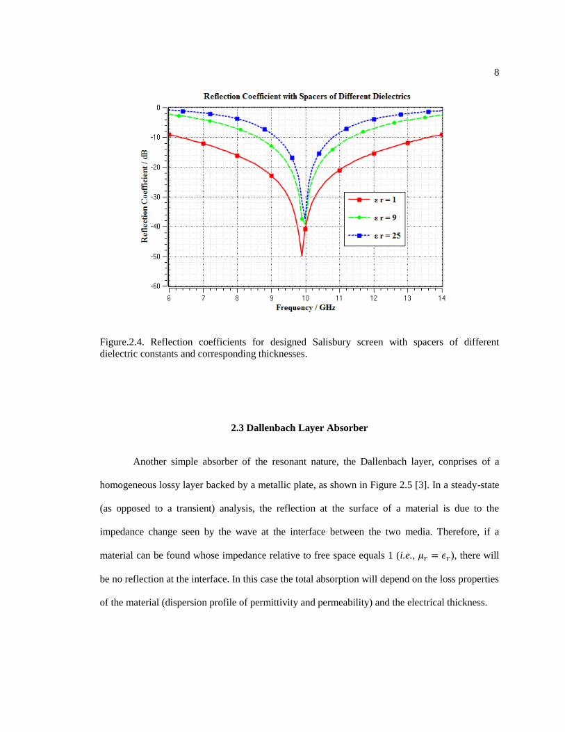
a quarter of the wavelength of the spacer material. Figure 2.4 shows the reflection coefficients of
three screens using different lossless dielectric spacers with a designed operating frequency at
10GHz. The reduction in thickness could be beneficial for certain practical applications.
However, such reduction in thickness is accompanied by a reduction in absorption bandwidth,
which is modest at best.
8
Figure.2.4. Reflection coefficients for designed Salisbury screen with spacers of different
dielectric constants and corresponding thicknesses.
2.3 Dallenbach Layer Absorber
Another simple absorber of the resonant nature, the Dallenbach layer, conprises of a
homogeneous lossy layer backed by a metallic plate, as shown in Figure 2.5 [3]. In a steady-state
(as opposed to a transient) analysis, the reflection at the surface of a material is due to the
impedance change seen by the wave at the interface between the two media. Therefore, if a
material can be found whose impedance relative to free space equals 1 (i.e., ), there will
be no reflection at the interface. In this case the total absorption will depend on the loss properties
of the material (dispersion profile of permittivity and permeability) and the electrical thickness.

9
Figure.2.5. Schematics for the Dallenbach Layer Absorber.
However, materials with appropriate dielectric and magnetic properties to act as a
perfectly matched RAM over any appreciable frequency range are difficult to find at best. So the
question becomes one of optimizing the loss at a given frequency using available materials. For a
single material layer backed by a conducting plate, the reflection coefficient is given by
(2.13)
where Z0 represents the intrinsic impedance of free space and Zin represents the
impedance seen by the wave at the air-absorber interface, which can be expressed as
(2.14)
where Zd represents the intrinsic impedance of the lossy layer and ZL is the intrinsic
impedance of the metallic plane, which is essentially 0, yielding the following reflection
coefficient:

10
(2.15)
It’s evident from (2.15) that given the material used to construct the Dallenbach layer
absorber, i.e., with the knowledge of the permittivity and permeability profile, the absorption
performance relies solely on the fraction of wavelength of the layer thickness.
One thing should be noted from the derived expression. The optimal choice of the
thickness for the lossy layer does not necessarily follow the straightforward quarter-wavelength
rule due to the potentially dispersive nature of the permittivity and permeability profile of the
lossy layer, nor does an increase in the thickness of the lossy layer guarantees a shift towards
lower frequencies for the absorption peak [4].
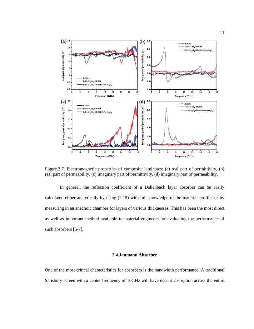
Figure 2.6 shows such an example of a Dallenbach layer absorber with different
thicknesses using materials whose electromagnetic properties are depicted in Figure 2.7.
Figure.2.6. Microwave absorption properties of the FePc–Fe3O4–BF/BPh/FePc–Fe3O4 composite
laminates.
11
Figure.2.7. Electromagnetic properties of composite laminates: (a) real part of permittivity, (b)
real part of permeability, (c) imaginary part of permittivity, (d) imaginary part of permeability.
In general, the reflection coefficient of a Dallenbach layer absorber can be easily
calculated either analytically by using (2.15) with full knowledge of the material profile, or by
measuring in an anechoic chamber for layers of various thicknesses. This has been the most direct
as well as important method available to material engineers for evaluating the performance of
such absorbers [5-7].
2.4 Jaumann Absorber
One of the most critical characteristics for absorbers is the bandwidth performance. A traditional
Salisbury screen with a center frequency of 10GHz will have decent absorption across the entire

12
X-band (Figure 2.3), but its performance will deteriorate for the remainder of the radar band—
spanning from 2GHz to 18GHz and beyond even that for certain applications.
The bandwidth of a Salisbury screen can be improved by adding additional resistive
sheets and spacers to form a Jaumann absorber [8]. Figure 2.8 shows an example of an eight-layer
Jaumann absorber. The thicknesses and sheet resistances for each layer are shown in Table 2.1
and 2.2, respectively [9]. Only air spacers are used in this example for simplicity of the analysis.
Table 2-1. Thicknesses for all the layers of the Jaumann absorber (mm)
d1 d2 d3 d4 d5 d6 d7 d8
3.9 3.9 4 3.9 3.9 3.9 4 3.9
Table 2-2. Sheet resistances for all the layers of the Jaumann absorber (Ω/sq)
Rs1 Rs2 Rs3 Rs4 Rs5 Rs6 Rs7 Rs8
305 579 873 1266.5 1796 2480 3724 2067

13
Figure.2.8. Schematics for an 8-layer Jaumann absorber.
Figure 2.9 shows the simulated reflection coefficient for the eight-layer Jaumann
absorber, with a 10dB absorption bandwidth of 2.5~36GHz and a 20dB absorption bandwidth of
2.95~35.2GHz. The total thickness for this Jaumann absorber is slightly larger than a quarter of
the wavelength at the lowest frequency (26.8%). Alternative approaches need to be considered to
further reduce the thickness of the Jaumann absorber while maintaining its ultra-wideband
performance.
Figure.2.9. Reflection coefficient for an 8-layer Jaumann absorber.
2.5 Summary
In this chapter, we have briefly reviewed the very cornerstone of electromagnetic
absorbers. The absorption performances for the traditional Salisbury screen, Dallenbach layer and

14
Jaumann absorber are evaluated and their advantages and disadvantages outlined. These legacy
designs will facilitate as theoretical basis as well as crucial components for various applications,
as will be demonstrated in the following chapters.

Chapter 3
Frequency Selective Surface (FSS)-based Absorber for Wideband
Applications
3.1 Introduction
One major branch of absorber design in contemporary research is focused on FSS-based absorber,
which comprise of an FSS screen printed above a dielectric substrate with a PEC backing. The
unit cell of the FSS commonly utilizes resonant structures that correspond to the working
frequency of the absorber. in common with the Salisbury screen, the FSS acts as an impedance
transformer [10], which transforms the input impedance of the absorber at the air-FSS interface to
that of the characteristic impedance of air, achieving perfect absorption at the design frequency.
As a result, the absorption performance is extremely narrowband unless the unit cell is designed
with multiple structures that correspond to resonant frequencies near the designed operating
frequency, contributing to wideband absorption characteristics [11].
A different approach to designing absorbers is presented in this chapter, which was
inspired by the reciprocity theorem. This approach is particularly useful when the bandwidth of
the absorber is of primary design concern. A systematic design procedure can be followed to meet
the desired specification in the operating frequency range.

16
3.2 General Reciprocity Theorem
The reciprocity theorem in electromagnetics is discussed in this section as a starting
point. This applies to the use of Maxwell’s equations. Assuming that within a linear and isotropic
medium, but not necessarily homogeneous, there exist two sets of sources (J1, M1,) and (J2, M2 )
which radiate simultaneously inside the same medium and at the same frequency, producing
fields (E1, H1 ) and (E2, H2) respectively. It can be shown [12], [13] that the sources and fields
satisfy
(3.1)
which is referred to in the literature as the Lorentz Reciprocity Theorem in integral form.
Another useful form of (3.1) is to consider that the fields (E1, H1, E2, H2) and the sources
(J1, M1, J2, M2) are within a medium that is enclosed by a sphere of infinite radius. Assume that
the sources are positioned within a finite region and that the fields are observed in the far field
(ideally at infinity). Then the left side of (3.1) is equal to zero, or
(3.2)
under these circumstances,
(3.3)
Equation (3.4) can also be written as
(3.4)
17
3.3 Reciprocity Theorem for Antenna Systems
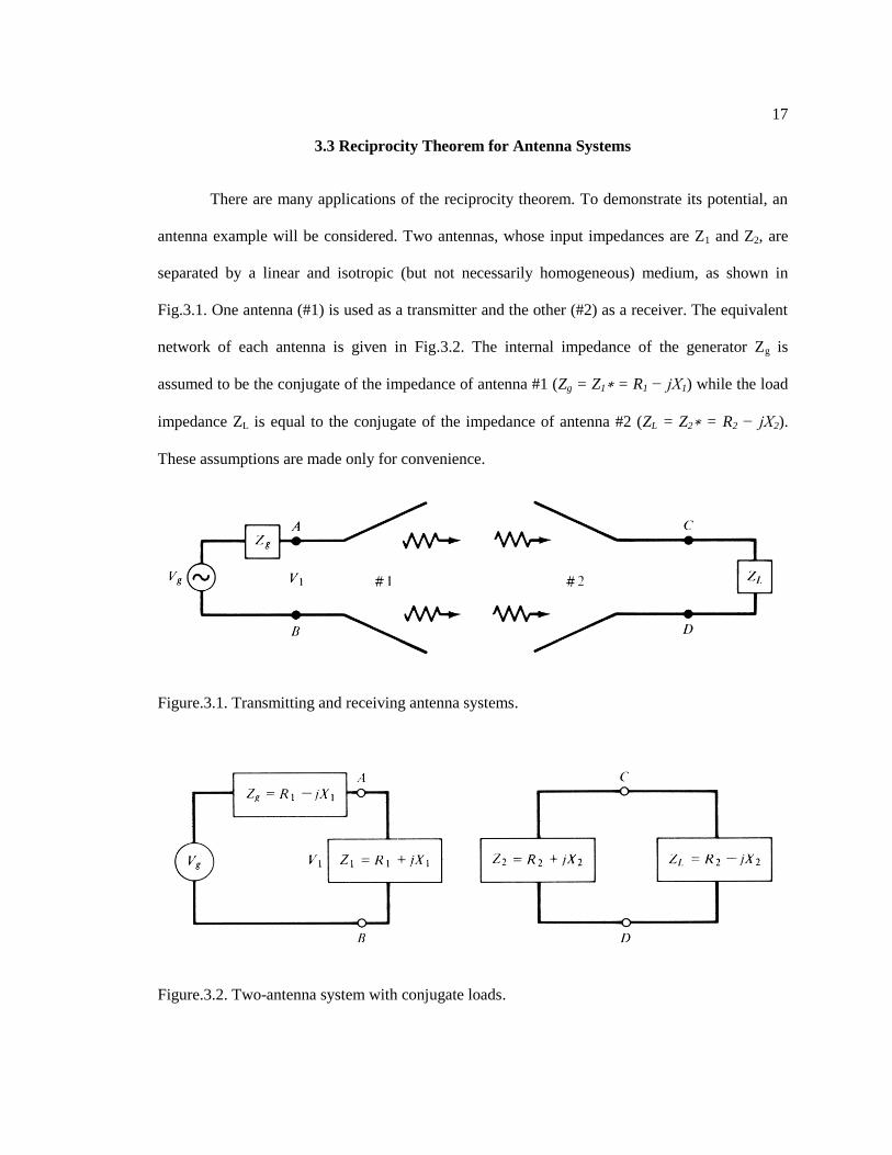
There are many applications of the reciprocity theorem. To demonstrate its potential, an
antenna example will be considered. Two antennas, whose input impedances are Z1 and Z2, are
separated by a linear and isotropic (but not necessarily homogeneous) medium, as shown in
Fig.3.1. One antenna (#1) is used as a transmitter and the other (#2) as a receiver. The equivalent
network of each antenna is given in Fig.3.2. The internal impedance of the generator Zg is
assumed to be the conjugate of the impedance of antenna #1 (Zg = Z1∗ = R1 − jX1) while the load
impedance ZL is equal to the conjugate of the impedance of antenna #2 (ZL = Z2∗ = R2 − jX2).
These assumptions are made only for convenience.
Figure.3.1. Transmitting and receiving antenna systems.
Figure.3.2. Two-antenna system with conjugate loads.

18
The power delivered by the generator to antenna #1 is given by (3.5)
∗
∗
∗
(3.5)
If the transfer admittance of the combined network consisting of the generator
impedance, antennas, and load impedance is Y21, the current through the load is VgY21 and the
power delivered to the load is
∗
(3.6)
The ratio of (3.6) to (3.5) is
(3.7)
Under conditions of reciprocity (Y12 = Y21), the power delivered in either direction is the
same.
Taking a cue from the reciprocity theorem, we specifically choose well-matched antenna
structures as unit cells, as electromagnetic wave receivers and converters.
3.4 Unit–Cell Design and Bandwidth Expansion
We start with the most fundamental type of antenna as the component of the unit cell. A
cross-dipole antenna is introduced to account for both polarizations and the feed is replaced by a
resistor patch to connect both arms of the dipole [14].
An example of such a screen is the periodic cross-strip structure consisting of conducting
arms (grey in color) and a load resistor (red in color), as shown in Fig.3.3. The cross-strip
structure is considered as a unit cell and the reflection coefficient for the screen is simulated for

19
the case where it is backed by a PEC sheet. An increase of bandwidth performance is achieved by
adding an additional layer of larger cross-strips with lower resonant frequencies. The reflection
coefficient for the cross-strip structures are shown in Fig.3.4.
Figure.3.3. (a,d) Isometric; (b,e) top; and (c,f) side view of the cross-strip model with inter-
connected resistors (red) and duo layer stack model, respectively (D=15, W=12, H=5.5, H’=11.5
unit: mm).

20
Figure.3.4. (a,d) Isometric; (b,e) top; and (c,f) side view of the cross-strip model with inter-
connected resistors (red) and duo layer stack model, respectively (D=15, W=12, H=5.5, H’=11.5
unit: mm).
3.5 Wideband Unit-Cells and Dual-Direction Capabilities
Next, to enhance the bandwidth of the screen we replace cross-strips with bowties, as
shown in Fig.3.5. In this design, conducting bowties (grey in color) are connected with load
resistors (red and pink in color). We have simulated a 3-layer configuration of this structure, and
Fig.3.6 shows that a wide absorption bandwidth can be achieved even in the absence of a PEC
backing, which provides both dual-directional absorption capabilities and desirable absorption
levels for applications in which the backing is not metallic.

21
Figure.3.5. Illustration of the (a) isometric; (b) top; (c) side view of the 3-layer bowtie absorber
model and the (d) 1st layer; (e) 2nd layer; (f) 3rd layer (L=53.4mm, W=21mm, d=6mm).
Figure.3.6. Reflection, transmission and absorption coefficient of the three layer absorber-screen
model.

22
3.6 Lossy FSS Analysis
Typically, of FSS-based absorber are realized by using lossy FSSs, with varying sheet
resistance, or unit cells comprising of with perfectly conducting strips with resistive inserts. We
start by examining the latter design, to see how we might enhance its performance.
We start with an existing design which has been proposed by Shang et al. [15],
comprising of a complex dual-loop absorber illustrated in Fig.3.7. The conducting strips forming
the loop can be segmented into various lengths to introduce multiple resonances. These parts can
then be connected together by resistive loads to lower the Q factor of the system. The multiple
resonances of the system can be adjusted to achieve a wideband performance (as shown in
Fig.3.8).

23
Figure.3.7. Schematics of the unit cell of an EM absorber based on dual-loop periodic screens,
model (a).

24
Figure.3.8. Reflected power level for the original dual-loop absorber.
In this section we compare the performances of three different configurations: (a) the
original design in [15] which has a resistively-loaded dual-loop (PEC); (b) a modified design with
a resistively-loaded dual-loop (lossy with a sheet resistance of 100Ω/sq) as shown in Fig.3.9; (c) a
complete dual-loop (lossy with a sheet resistance of 100Ω/sq) as shown in Fig.3.10.
The loop sizes as well as the load resistances are chosen to be the same in all cases, and
all of the three screens are backed by a PEC ground plane with a 14.7mm air spacer, which is
identical to that in [15].

25
Figure.3.9. Schematics of the unit cell of a modified EM absorber utilizing lossy, complex dual-
loop periodic screens, model (b).
Figure.3.10. Schematics of the unit cell of a modified EM absorber based on lossy, dual-loop
periodic screens without segmentation, model (c).
The absorption characteristics of the configurations in (a) and (b) are presented in
Fig.3.11 for varying sheet resistances.

26
Figure.3.11. Reflected power level for model (b) with varying sheet resistance.
The peak absorption frequency for configuration (b) can be systematically tuned by
adjusting the sheet resistance of the unsegmented dual-loop, but without changing the operational
bandwidth. Such a feature could be useful when designing absorbers with band-suppression
requirements [16].
Fig.3.12 compares the performances of the configurations (a) and (c) when their sheet
resistance is varied. We observe that the unsegmented dual-loop configuration preserves the
multiple resonance characteristic of the original segmented design when the sheet resistance is
chosen appropriately. The peak absorption frequency can also be tailored by changing the sheet
resistance of the dual-loop, though at some expense of the overall bandwidth.

27
Figure.3.12. Reflected power level for model (c) with varying sheet resistance.
Two different modifications of an FSS-based EM absorber comprising of resistively
loaded dual-loops have been studied. It is shown that varying the sheet resistance of the periodic
screen can achieve enhanced absorption at frequencies where a high absorption level is desired,
with little compromise of its bandwidth performance.

Chapter 4
Multi-Layered Absorber for Ultra Wideband Applications
4.1 Design of Multilayered Absorber
Our objective is to design wideband layered absorbers for infinite, planar, conducting ground
planes. We note that this is also the basic approach to designing coating for radar targets to render
them stealthy, regardless of their shapes. Furthermore, it is relatively easy to carry out this design
by using optimization algorithms to determine the material properties and the layer thicknesses to
reduce the reflection from the coated PEC plane below -10dB level, and over a wide frequency
band; say covering radar frequencies from 2 to 18 GHz, for example.
4.1.1 Reflection Coefficient for obliquely incident stratified isotropic dielectric layers with a
PEC ground plane
We start by examining the analytical expression for the reflections coefficient for an
obliquely incident plane wave upon a dielectric layer with a PEC back, illustrated in Fig.4.1.

29
Figure.4.1. (a) TE and (b) TM wave incident obliquely on a multi-layer dielectric with a PEC
ground plane.
For the case of a TE plane wave incident on a single layer, the fields inside medium 1 are
of the form:
(4.1)
The fields inside medium 2 are of the form:
(4.2)
The coefficients for the fields are calculated by applying the boundary conditions at
different interfaces, which are found to be:
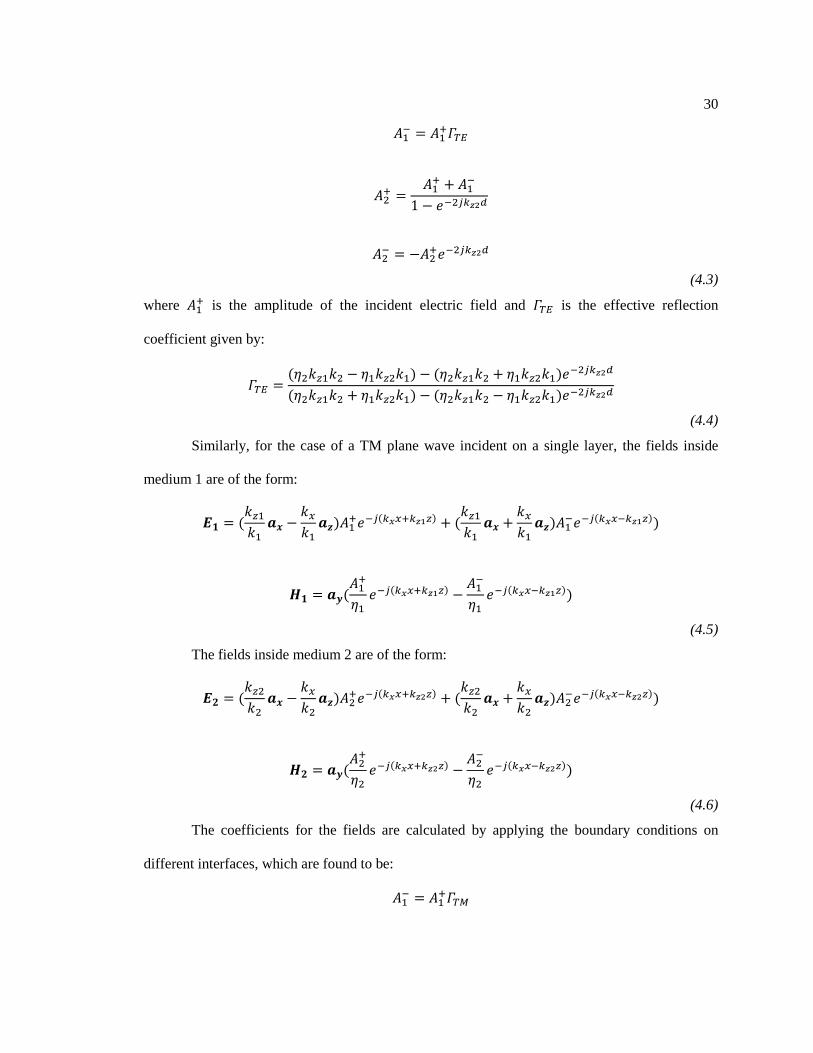
30
(4.3)
where is the amplitude of the incident electric field and is the effective reflection
coefficient given by:
(4.4)
Similarly, for the case of a TM plane wave incident on a single layer, the fields inside
medium 1 are of the form:
(4.5)
The fields inside medium 2 are of the form:
(4.6)
The coefficients for the fields are calculated by applying the boundary conditions on
different interfaces, which are found to be:
31
(4.7)
where is the amplitude of the incident electric field and is the effective reflection
coefficient given by:
(4.8)
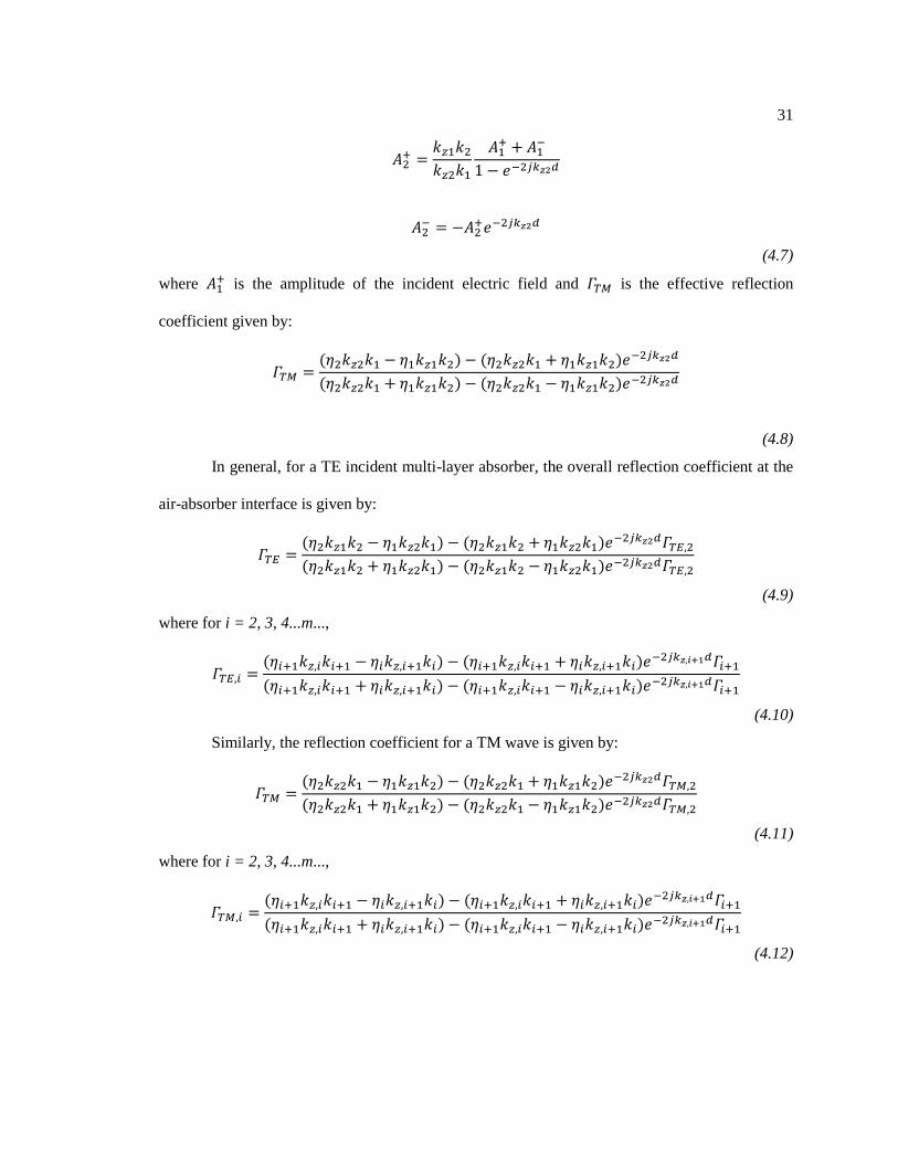
In general, for a TE incident multi-layer absorber, the overall reflection coefficient at the
air-absorber interface is given by:
(4.9)
where for i = 2, 3, 4...m...,
(4.10)
Similarly, the reflection coefficient for a TM wave is given by:
(4.11)
where for i = 2, 3, 4...m...,
(4.12)

32
4.1.2 Optimization Process for Maximizing Frequency Bandwidth and Minimizing
Thickness
The single-layered Dallenbach absorber has obvious limitations in terms of bandwidth
and thickness. It is common practice to use multiple layers of absorbing materials to meet
bandwidth specifications and reduce the overall thickness as much as possible. Several
optimization algorithms, such as the Genetic Algorithm (GA) and Particle Swarm Optimization
(PSO), have been developed to search for an optimal arrangement of the different layers of
absorbers so that a continuous wideband absorption performance can be achieved. This has been
vitally important since most synthetic-type real-world absorbing materials have a high level of
dispersion, making a purely analytical approach to finding the optimal arrangement for the
thicknesses of the absorber layers an extremely challenging task, if not impossible.
A typical cost function to be minimized, which is suitable for optimizing the layer
thicknesses while balancing the absorption performance and overall thickness can be defined as
follows:
∗ ∗
(4.13)
where di represents the thickness for each layer of the absorber; RL stands for the reflection level
at the air-absorber interface and is a function of the material parameters and thicknesses di of the
absorbing layers (Fig.4.2); and m is the weight of the reflection level in the optimization,
signifying the importance of the reflection level over the collective thickness of the layered
absorber. Note that m = 1 corresponds to the case where the total thickness is predetermined, and
only the reflection coefficient is minimized. Note that the parameters of the materials available to
us are dispersive, and hence the optimization to determine the thicknesses should be carried out
over the entire desired frequency band.

33
Figure.4.2. Model schematics of the optimization problem for the multilayer absorber.
As is well known, the RAMs (radar absorbing materials) have been around for a very
long time, some for many decades, dating back to when stealth aircrafts came into vogue in the
sixties, although earliest theoretical and experimental work date back to 1940s. We realize that
information on some of these RAM materials is not openly available because of their “classified”
or “secret” nature, understandably so because they are used in military applications to design
stealth aircrafts and missiles. Nonetheless, a plethora of information about similar absorbing
materials is available in the open literature, including the details of their fabrication, which have
been described in [2], for instance.
Here we will use two different types of materials namely CoFe Nano-Flakes (NF) and
CoFe Nano-Particles (NP), whose frequency variations are shown in Fig.4.3. We point out that
these materials can be realized with relative ease, as is evident from [17, 18], where the details of
their fabrication can be found.

34
Figure.4.3. Real and imaginary parts of the (a) permittivity and (b) permeability for the two types
of absorbing materials used in the multi-layer absorbing blanket design.
To illustrate the fact that we can indeed achieve wideband performance in terms of
reflection reduction over a wide frequency band with relative small thicknesses of 2, 4, 6 and 7
layer absorbers we refer to Fig.4.4, in which a 10dB (or better) reduction in the reflection
coefficient is presented. Although not shown here, the results for the reflection coefficient
reduction are also satisfactory when either the polarization, or the incident angle is varied and this
is also true when both are changed simultaneously.

35
Figure.4.4. Reflection coefficient of multilayer absorber backed by a PEC plate for different
number of layers.
4.2 RCS Reduction for Test Targets
The multi-layer absorber designed for the infinite PEC plane is applied to an arbitrarily-
shaped object. Initially we consider an object with a smooth surface whose radius of curvature is
moderate-to-large everywhere. Fig.4.5 shows the back-scattering RCS level of three PEC
structures each treated with the 2-layer and 7-layer absorber developed in Sec.4.1.2 and compared
with the original PEC configurations, where the incident wave propagates along -Z direction.

36
Figure.4.5. Back-scattering RCS of PEC objects: (a) plate, (b) pyramid, and (c) cylinder covered
with 2 and 7-layer absorbers.
37
4.3 FSS and Multi-Layered Composite Absorber for Performance Enhancement
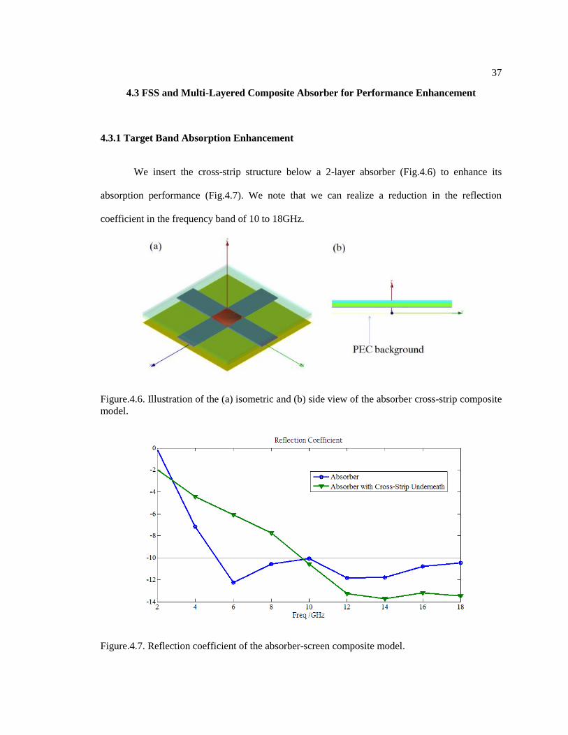
4.3.1 Target Band Absorption Enhancement
We insert the cross-strip structure below a 2-layer absorber (Fig.4.6) to enhance its
absorption performance (Fig.4.7). We note that we can realize a reduction in the reflection
coefficient in the frequency band of 10 to 18GHz.
Figure.4.6. Illustration of the (a) isometric and (b) side view of the absorber cross-strip composite
model.
Figure.4.7. Reflection coefficient of the absorber-screen composite model.
38
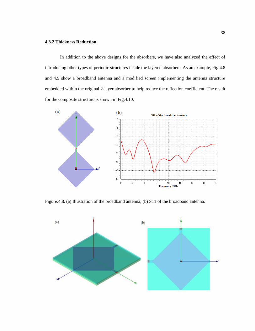
4.3.2 Thickness Reduction
In addition to the above designs for the absorbers, we have also analyzed the effect of
introducing other types of periodic structures inside the layered absorbers. As an example, Fig.4.8
and 4.9 show a broadband antenna and a modified screen implementing the antenna structure
embedded within the original 2-layer absorber to help reduce the reflection coefficient. The result
for the composite structure is shown in Fig.4.10.
Figure.4.8. (a) Illustration of the broadband antenna; (b) S11 of the broadband antenna.
39
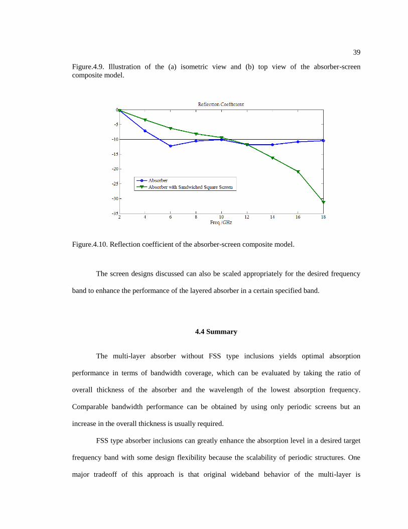
Figure.4.9. Illustration of the (a) isometric view and (b) top view of the absorber-screen
composite model.
Figure.4.10. Reflection coefficient of the absorber-screen composite model.
The screen designs discussed can also be scaled appropriately for the desired frequency
band to enhance the performance of the layered absorber in a certain specified band.
4.4 Summary
The multi-layer absorber without FSS type inclusions yields optimal absorption
performance in terms of bandwidth coverage, which can be evaluated by taking the ratio of
overall thickness of the absorber and the wavelength of the lowest absorption frequency.
Comparable bandwidth performance can be obtained by using only periodic screens but an
increase in the overall thickness is usually required.
FSS type absorber inclusions can greatly enhance the absorption level in a desired target
frequency band with some design flexibility because the scalability of periodic structures. One
major tradeoff of this approach is that original wideband behavior of the multi-layer is

40
compromised and reduced to the target band because the standalone bandwidth of the FSS type
absorber is usually smaller than that of the multi-layer absorber.
Chapter 5
Cloaking and Scattering Reduction
5.1 Introduction
The objective of this chapter is twofold. First of these is to review the basic principles of the
Transformation Optics (TO) approach, also known as Transformation Electromagnetics (TEM)
algorithm, which has recently surfaced as one of the most innovative techniques for designing a
wide variety of electromagnetic devices including cloaks to render objects invisible. Our second
goal is to present an alternative approach for designing absorptive coatings for scattering
reduction, which differs from that used to design TO-based cloaks, and avoids the problems of
narrow bandwidth and sensitivity to polarization and incident angle associated with the TO-based
cloaks that we realize by using Metamaterials (MTMs).
The TO algorithm for designing cloaks is unique in that it provides a systematic
approach, which is very innovative, as well as elegant, and is markedly different from the
techniques that have been employed heretofore prior to the advent of the TO, to design RCS-
reducing absorbers, for example.
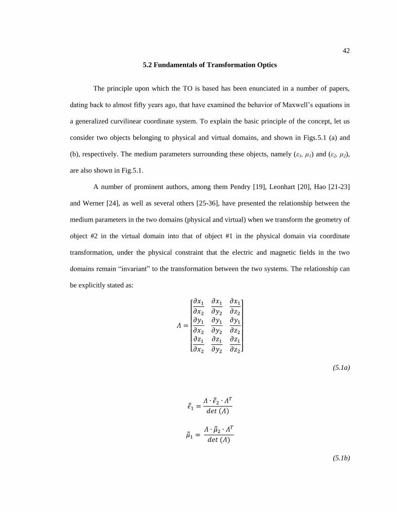
Figure.5.1. (a) Physical and (b) virtual domains used in the TO algorithm.
42
5.2 Fundamentals of Transformation Optics
The principle upon which the TO is based has been enunciated in a number of papers,
dating back to almost fifty years ago, that have examined the behavior of Maxwell’s equations in
a generalized curvilinear coordinate system. To explain the basic principle of the concept, let us
consider two objects belonging to physical and virtual domains, and shown in Figs.5.1 (a) and
(b), respectively. The medium parameters surrounding these objects, namely (ε1, μ1) and (ε2, μ2),
are also shown in Fig.5.1.
A number of prominent authors, among them Pendry [19], Leonhart [20], Hao [21-23]
and Werner [24], as well as several others [25-36], have presented the relationship between the
medium parameters in the two domains (physical and virtual) when we transform the geometry of
object #2 in the virtual domain into that of object #1 in the physical domain via coordinate
transformation, under the physical constraint that the electric and magnetic fields in the two
domains remain “invariant” to the transformation between the two systems. The relationship can
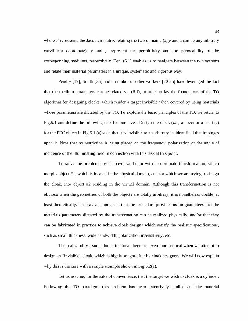
be explicitly stated as:
(5.1a)
(5.1b)
43
where Λ represents the Jacobian matrix relating the two domains (x, y and z can be any arbitrary
curvilinear coordinate), ε and μ represent the permittivity and the permeability of the
corresponding mediums, respectively. Eqn. (6.1) enables us to navigate between the two systems
and relate their material parameters in a unique, systematic and rigorous way.
Pendry [19], Smith [36] and a number of other workers [20-35] have leveraged the fact
that the medium parameters can be related via (6.1), in order to lay the foundations of the TO
algorithm for designing cloaks, which render a target invisible when covered by using materials
whose parameters are dictated by the TO. To explore the basic principles of the TO, we return to
Fig.5.1 and define the following task for ourselves: Design the cloak (i.e., a cover or a coating)
for the PEC object in Fig.5.1 (a) such that it is invisible to an arbitrary incident field that impinges
upon it. Note that no restriction is being placed on the frequency, polarization or the angle of
incidence of the illuminating field in connection with this task at this point.
To solve the problem posed above, we begin with a coordinate transformation, which
morphs object #1, which is located in the physical domain, and for which we are trying to design
the cloak, into object #2 residing in the virtual domain. Although this transformation is not
obvious when the geometries of both the objects are totally arbitrary, it is nonetheless doable, at
least theoretically. The caveat, though, is that the procedure provides us no guarantees that the
materials parameters dictated by the transformation can be realized physically, and/or that they
can be fabricated in practice to achieve cloak designs which satisfy the realistic specifications,
such as small thickness, wide bandwidth, polarization insensitivity, etc.
The realizability issue, alluded to above, becomes even more critical when we attempt to
design an “invisible” cloak, which is highly sought-after by cloak designers. We will now explain
why this is the case with a simple example shown in Fig.5.2(a).
Let us assume, for the sake of convenience, that the target we wish to cloak is a cylinder.
Following the TO paradigm, this problem has been extensively studied and the material

44
parameters for the cloak have been derived by invoking the TO, which makes the cloaked object
disappear entirely (become invisible). In Figs.5.2(b) and (c) we plot the material parameters,
presented in [37], that are required to make the cylinder invisible.
Figure.5.2. (a) Schematics for a cloaked PEC cylinder with R2 = 2R1, (b) material parameters for
an all-angle, all-polarization cloak, (c) material parameters for a normal-incident, TE-polarization
cloak from [37].
We observe several things from Fig.5.2. First, we see that the material parameters are
anisotropic, and this in of itself can be problematic when we attempt to realize them in practice,
because there is no systematic method available for synthesizing them. The second thing we
observe about the required μ and ε values is that they vary over a wide range, tending to 0 in some
regions and ∞ in others. Once again, this type of inhomogeneous behavior and a wide swing in
the required material parameters as functions of the radial distance make it very difficult to
realize them. In fact, we must resort to using Metamaterials (aka artificially-engineered materials)
that are notoriously narrowband, dispersive and lossy where they attempt to realize the above
type of material values. The above undesirable attributes that degrade the performance of the
45
cloak and render it unsuitable for most applications that involve scattering reduction for real-
world targets. What exacerbates the problem even more is the fact that the thickness of the cloak
is comparable to the wavelength, rather than being a small fraction of the same. As we well know,
a thin coating is desired in most applications, e.g., when designing stealth targets for the radar
world.
At this point we return to the TO paradigm for cloak designs and scrutinize it carefully to
see if we can thresh out the root causes of the difficulties that we have just identified with the TO-
based design, where upon introduction of Metamaterials for physical realization of the cloak
structure. Note that polarization-insensitive Metamaterial designs for TO-based cloaks will be
extremely challenging and the usual simplification is to limit the polarization to a certain linear
polarization. This introduces polarization sensitivity of the cloaks. Another example is that typical
Metamaterials are designed using periodic structures and the unit cell details are optimized for a
single angle of incidence (usually normal to the interface). This introduces sensitivity to the angle
of incidence.
To identify the problem areas with the TO-based cloak designs, we turn to an alternate
derivation of the material parameters in the context of Transformation Electromagnetics. Rather
than relying directly on the Jacobian of the transformation, which relates the Physical domain to
the corresponding virtual domain, we turn to the integral forms of Maxwell’s equations appearing
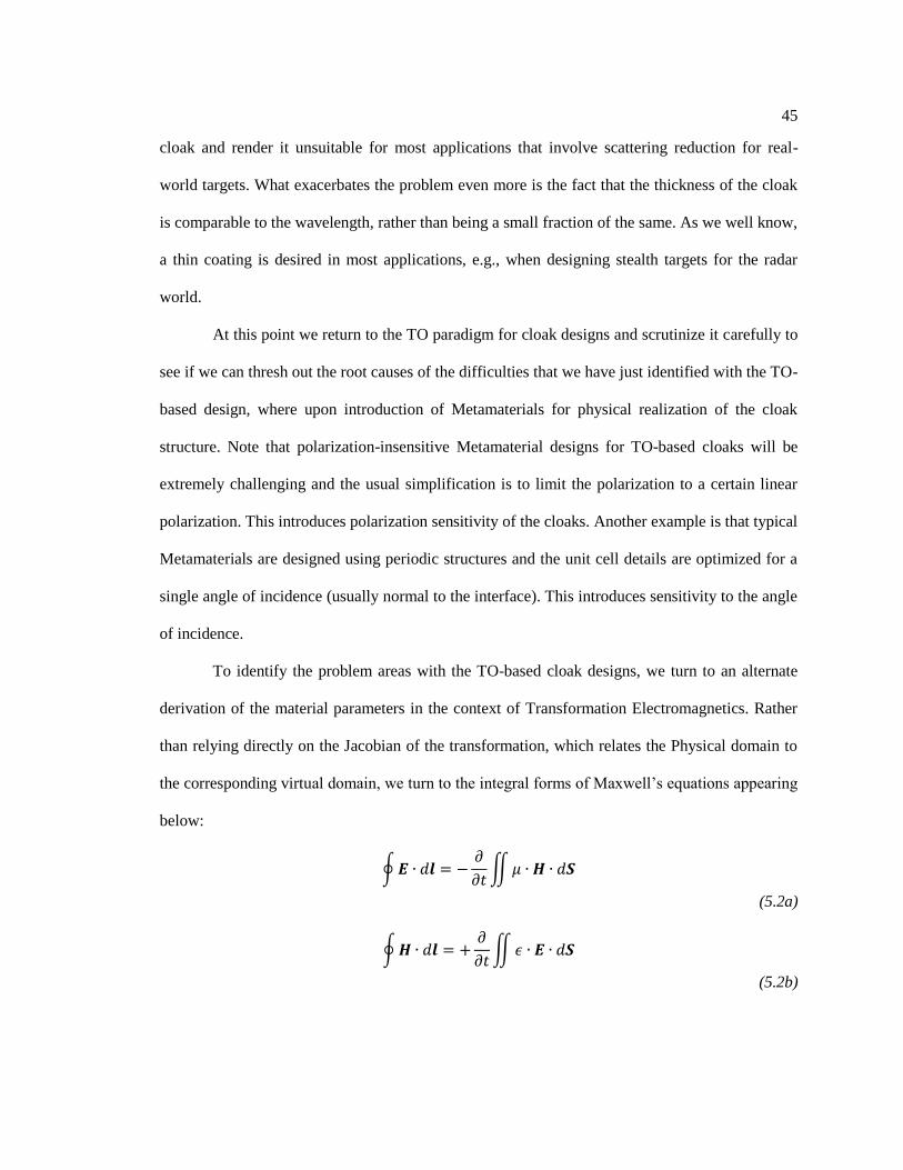
below:
(5.2a)
(5.2b)

46
Initially, we consider the relatively simple case where the two domains are simply related
by scaling, say by a factor ‘γ’, as has been done in the previous TO-based cloak designs [9].The
method we propose to relate the material parameters in the two domains is very general and is
applicable to the case where the two geometries have arbitrary shapes, and are not simply related
to each other by a scale factor, as we will discuss later.
Figure.5.3 TO-based cloak schematics and corresponding materials in the (a) physical geometry
and (b) virtual geometry.
To derive the material properties of the physical domain, from the assumed parameters in
the virtual domain (ε0, μ0 for free-space in this example), we turn to Fig.5.3 and Eqn.(5.2). The
next step, we choose to impose the condition that the fields ) in the physical domain be
“identical” to those in the virtual domain, i.e., ). To facilitate the imposition of this
condition, we now discretize the two domains, as shown in Fig.5.4, by setting up a mesh to
discretize the regions-2 and -3 in both domains. We take advantage of the circular symmetry of
the geometries in the two domains, and of the fact that the geometry of the PEC cylinder, located
in region-2 in the virtual domain is simply a scaled-down version of the one in the physical
domain (region-1), and note that this transformation preserves the azimuthal symmetries of the
two domains and, hence, the mesh size in the azimuthal direction remains unchanged when we
47
navigate between the two domains. However, we follow a different strategy in the radial
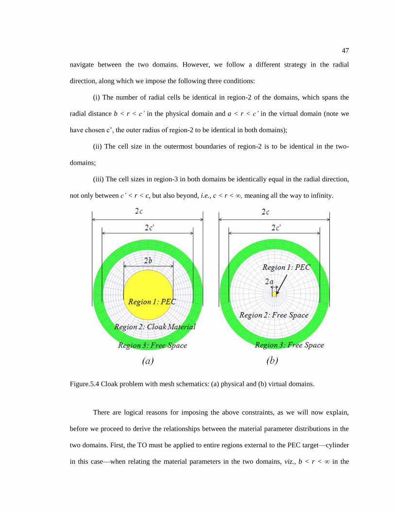
direction, along which we impose the following three conditions:
(i) The number of radial cells be identical in region-2 of the domains, which spans the
radial distance b < r < c’ in the physical domain and a < r < c’ in the virtual domain (note we
have chosen c’, the outer radius of region-2 to be identical in both domains);
(ii) The cell size in the outermost boundaries of region-2 is to be identical in the two-
domains;
(iii) The cell sizes in region-3 in both domains be identically equal in the radial direction,
not only between c’ < r < c, but also beyond, i.e., c < r < ∞, meaning all the way to infinity.
Figure.5.4 Cloak problem with mesh schematics: (a) physical and (b) virtual domains.
There are logical reasons for imposing the above constraints, as we will now explain,
before we proceed to derive the relationships between the material parameter distributions in the
two domains. First, the TO must be applied to entire regions external to the PEC target—cylinder
in this case—when relating the material parameters in the two domains, viz., b < r < ∞ in the

48
physical domain and a < r < ∞ in the virtual model. Specifically, we cannot truncate the regions
as we transform from one domain to another, without introducing discontinuities in the fields, and
thus violating the premise of TO under which we are operating. If we use condition (iii), in (5.2a
and 5.2b), we immediately see that if the two fields as well as the mesh sizes would be identical
in the two domains. It follows, then, that the material parameters must be exactly the same in
regions-3 in the two domains. Since we have chosen the material parameters in the virtual domain
in region-3 to be free-space, i.e., these parameters are ε0 and μ0, then region-3 in the physical
domain must correspond to free-space as well, as would the parameters of the external region c’
< r < ∞. This is a crucial point, and it implies that the cloak in the physical domain has but a
finite thickness, spanning the region b < r < c’. This is obviously necessary in order for the cloak
design to be practical, since we cannot accept a cloak design whose thickness is infinite, as it
would be if we did not impose the equal-mesh-size condition in the two domains in region-3 and
beyond, i.e., for r > c’.
To solve this problem we turn to the differential form of the Maxwell’s Equations given
below:
(5.3a)
(5.3b)
where ⊿l, ⊿S, and ⊿t represent the perimeter of a cell, surface area of a cell and time step in
FDTD, respectively. Note that we are considering only the Ez and Hϕ components for this 2D
geometry, namely a cylinder, for which z is along the axis of the cylinder, and ε and μ in (5.3) are
the appropriate elements of the and tensors.

49
Let us now turn to the regions-2 in the two domains, namely physical and virtual. Recall
that we have imposed the condition that the cell size at the outermost boundary of this region be
identical in the two domains, which guarantees that the transition of the material parameters
would be smooth as we transition from region-2 to region-3. (Recall region-3 and beyond is free-
space in both domains.) So, all that remains for us to do now is to determine the material
parameters of the cloak region in the physical domain, which spans from b < r < c’, by invoking
the condition that the fields of the physical domain be identical to the fields in
the virtual domain (which we have chosen to be free space), as well as condition (i) on the
number of cells in the two domains associated with region-2, namely that this number be identical
in the two domains. At this point, we impose an additional condition, without loss of generality,
that in the radial direction the cell sizes in region-2 in the physical domain be all equal, as we go
from r = b to r = c’. We also choose the cell size in the radial direction to be λ/20, though there is
no hard and fast rule that says that we must adhere to this last condition, which is dictated more
by the numerical discretization of the integral forms of Maxwell’s equations (5.3), than by
anything else. At this point, we note that since the dimensions of region-2 in the physical and
virtual domains are different, we typically choose the radius a such that a << b, in order to ensure
that the scattering from the small cylinder in the virtual domain would be small—in fact
vanishingly small in the ideal case—in order to render it invisible as a→0 in the limit. Note that
we must choose a non-uniform mesh in the virtual domain, so that we can simultaneously satisfy
condition (iii), as well as the constraint on the number of cells in the radial direction in the two
domains, namely that they be equal. Though we have some flexibility in terms of the variation of
the cell size in the radial direction in the virtual domain, we choose this variation in Δr to be
smooth, and monotonically increasing in terms of the cell size as we go from r = a to r = c’, so
that the summation of all the Δr’s equal (c’ − a). An example of such a mesh is shown in Fig.5.5.

50
Figure.5.5 Cloak problem with mesh schematics: (a) physical and (b) virtual domains.
Having defined the meshes in the two domains, we finally turn to the task of determining
the material parameters of the cloak in the physical domain. Recall that we wish to impose the
criterion that the two sets of fields, namely and in the two domains,
respectively, be identical. Eqn. (5.2) tells us that the (ε1 and μ1) values in the physical domain,
must be ε0/γn and μ0/γn, where γn is the ratio of the areas of the nth cell in the physical and virtual
domains, respectively. It is evident that, under these conditions, the ε1 and μ1 must start out at ε0/γ1
and μ0/γ1, where γ1 is the ratio of the dimensions of the first cell (at r = b) in the physical domain
to that of the dimension of its counterpart (at r = a) in the virtual domain. Also, we recall from
our previous discussion, that ε and μ values are identical in both domains when we reach r = c’,
and that they are both just (ε0 and μ0), i.e., material parameters of free space.

51
We now make two important observations. First, the cloak we have designed by
following the procedure just described, which is based on the TO algorithm—though
implemented differently than via the use of the Jacobian—varies inhomogeneously in the radial
direction, albeit smoothly. Second, the ε and μ values in the physical domain are larger, by a
factor of 1/γ1, than their free-space counterparts. This factor is responsible for the root cause of
difficulty encountered when designing TO-based cloaks, since it calls for Metamaterials to fulfill
the requirements on the material parameters if we insist that the cloak must render the target
totally “invisible”. This is because we can fulfill that condition if and only if a → 0, in the
strictest sense, and this implies that γ1 must also follow suit and tend to zero as well.
We should mention that although we chose the simple geometry of the cylinder to
identify the fundamental difficulties with the implementation of the TO paradigm, the problem
with the realization of material parameters persists regardless of the geometry of the target, as
long as we insist that it becomes invisible, which in turn requires that the scale factor (equivalent
to γ) tends to 0.
Before we discuss our strategy for overcoming this fundamental roadblock, we examine
another fundamental limitation posed by the TO paradigm when we attempt to reduce the
thickness of the cloak t ( = c’− b ),to realistic values, e.g., a small fraction of the wavelength. We
note that the material values (ε0 and μ0) near the outer boundary of the cloak, located at r = c’, do
not change, regardless of whether r is large or small, and, for that matter neither do the behaviors
of (ε and μ) of the cloak in the neighborhood of r = b, where the above parameters → ∞. While
we can attempt to partially mitigate this problem by imposing a cap on the values of these
parameters, we cannot change the fact that the relative εn and μn must reduce from very large
values at the surface of the cylinder to unity within a relatively short distance; and this, in turn,
again poses realizability problems in practice. For this reason, practical realizability of thin
invisibility cloaks have not met with too much success in the past, and it is unlikely that the
52
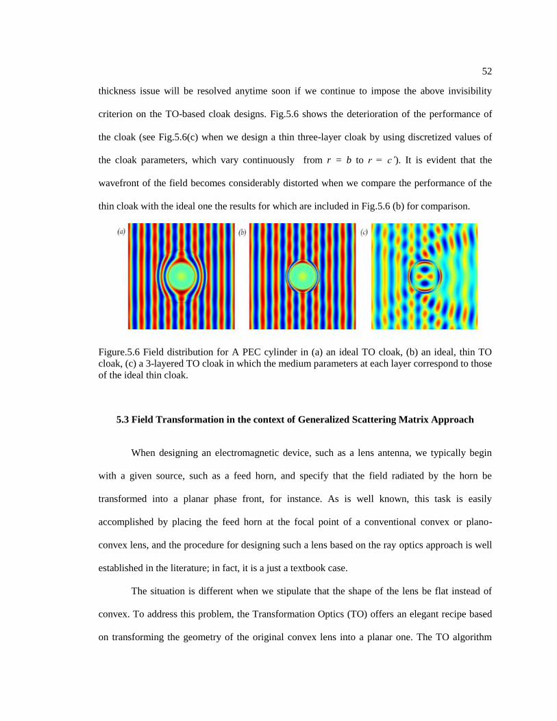
thickness issue will be resolved anytime soon if we continue to impose the above invisibility
criterion on the TO-based cloak designs. Fig.5.6 shows the deterioration of the performance of
the cloak (see Fig.5.6(c) when we design a thin three-layer cloak by using discretized values of
the cloak parameters, which vary continuously from r = b to r = c’). It is evident that the
wavefront of the field becomes considerably distorted when we compare the performance of the
thin cloak with the ideal one the results for which are included in Fig.5.6 (b) for comparison.
Figure.5.6 Field distribution for A PEC cylinder in (a) an ideal TO cloak, (b) an ideal, thin TO
cloak, (c) a 3-layered TO cloak in which the medium parameters at each layer correspond to those
of the ideal thin cloak.
5.3 Field Transformation in the context of Generalized Scattering Matrix Approach
When designing an electromagnetic device, such as a lens antenna, we typically begin
with a given source, such as a feed horn, and specify that the field radiated by the horn be
transformed into a planar phase front, for instance. As is well known, this task is easily
accomplished by placing the feed horn at the focal point of a conventional convex or plano-
convex lens, and the procedure for designing such a lens based on the ray optics approach is well
established in the literature; in fact, it is a just a textbook case.
The situation is different when we stipulate that the shape of the lens be flat instead of
convex. To address this problem, the Transformation Optics (TO) offers an elegant recipe based
on transforming the geometry of the original convex lens into a planar one. The TO algorithm

53
then shows us how to derive the requisite material parameters of the planar lens by using well-
established relationships between the ε and μ values of the original convex lens and its
surrounding medium, and those of its planar counterpart. These relationships involve the
Jacobians of the geometry transformation and are relatively straightforward to find, even for
arbitrary geometries being transformed from the real space to virtual space. The caveat, though, is
that the ε and μ values are in general anisotropic and may be difficult if not virtually impossible
to realize in practice. It is not uncommon, therefore, to set the μ values equal to μ0, i.e., that of free
space, to ignore the ε values less than unity, and to only work with isotropic dielectrics, albeit at
the risk of compromising the performance of the lens in comparison to that of the original TO-
design prior to introducing the modifications. What is equally important to realize is that there is
no clear roadmap provided by the TO algorithm that tells us how we can improve the
performance of the modified design, should we need to do so.
Given this background, we pose the following question for ourselves: Can we modify the
problem statement that forms the basis of the TO algorithm to circumvent the problems alluded to
above, without compromising the performance relative to that of the convex lens, in way such
that we can still use realizable materials found in nature, and without having to resort to MTMs?
We will now present an approach based on the Generalized Scattering Matrix (GSM) method
[38], which indeed offers a way to address the problem at hand, as we have just enunciated above.
To introduce the GSM approach in the context of Field Transformation method we refer
the reader to Fig.5.7, where we have defined the input and output ports to correspond to interfaces
that bound an electromagnetic device. The field distribution in the input port, which is illuminated
by the source located at the left of the port, can be expressed in terms of a set of coefficients
ai1(vector) associated with the basis functions employed to represent this “incident” field in the
absence of the device when there are no reflections. Next, we insert the electromagnetic device,
whose Scattering Matrix we desire to describe, inside the region bracketed by the input and

54
output ports. We define a set of coefficients bi1, again associated with the same basis functions as
we used to define ai1, to represent the outgoing fields scattered by the electromagnetic device, i.e.,
the “reflected” fields that originate from the device and propagate back towards the source We
can similarly define a set of coefficients ci1,associated with the field distribution in the output
port, through which these fields propagate in the free-space region to the right of this port, and are
termed the “transmitted” fields. Our next step is to place the illuminating source to the right of the
output port, which we have previously defined when the source was at the left, and reverse the
roles of the input and output ports to correspond to the new source location. The incident,
reflected, and transmitted fields are now characterized by a new set of coefficients ai2, bi
2, and ci
2
, where ci2 fields now propagate to the left of the device, whereas the bi2fields do the opposite,
i.e., propagate to the right.
Figure.5.7 Generalized Scattering Matrix (GSM) approach in the context of the Field
Transformation (FT) method.
We are now ready to define the scattering matrix [S], via (5.4) below, which we will use
to characterize the device, as follows:
55
(5.4)
or explicitly,
(5.5)
where b ={b1, b2} and a ={a1,a2} represent the weights of the outgoing and incoming field
representations at the input and output ports, respectively. Eqn. (5.2) provides us a convenient
way to characterize an electromagnetic device in terms of its response to a plane wave, regardless
of whether the illuminating source is incident from the left or the right of the device.
We will now explain how we can specify the desired characteristics of a device in terms
of its S-parameter description by turning to the problem of reducing the level of scattering from
radar targets—a problem that has been extensively researched into in the context of the TO. We
will cast the problem in the language of Scattering Matrices, to help us understand why the TO
approach leads us to untenable situations and/or to solutions which call for MTMs that are lossy,
dispersive, polarization-dependent and have narrow bandwidths in terms of frequency of
operation. We will also show how the FT approach mitigates the problems alluded to above by
restating the design objectives and modifying them slightly from those associated with the TO-
based designs.
Let us consider an arbitrarily shaped radar target placed in the region between the input
and output ports as shown in Fig.5.8. Next, let us suppose that our objective is to reduce the level
of scattering from the target, both in the forward and backward directions to the extent that the
target becomes totally invisible to the incident field, say from an interrogating radar. We could
cast this objective in the language of the Scattering matrices, by specifying that S11 be identically
zero at the input port and S12 be such that the field distribution at the output port is identical to
the incident field, as though the scatterer was totally transparent or invisible. This is precisely the
premise upon which the TO algorithm is based, and the TO shows how to achieve this goal by

56
filling the center region, which contains the target, with materials that cloak the target to render it
invisible, just as though it were absent. While such a goal is highly attractive, it is also very
unrealistic, insofar as the physical realization of the cloak is concerned, for several reasons: first,
the materials called for by the TO algorithm are highly anisotropic, even for simple targets such
as cylinders; second, the requisite material values span a wide range, as shown in Figs.5.2 for a
cylindrical target; third, these materials can only be realized by artificially synthesizing them, i.e.,
by using metamaterials that are inherently lossy, dispersive and narrowband (bandwidth is
typically on the order of a few percent of the center frequency); fourth, the design is dependent on
the incident angle as well as the polarization of incident wave—which makes it very impractical
for real-world applications; fifth, the thickness of the cloak is much too large for real-world
applications at microwaves; sixth, the TO algorithm does not provide a clue for systematically
applying it to realistic targets that can be highly inhomogeneous—not made of just PEC but
composite materials as well. (A literature research has failed to reveal the existence of such
cloaks though we conjecture that there must have been many failed attempts to address this
problem by workers in this field.)
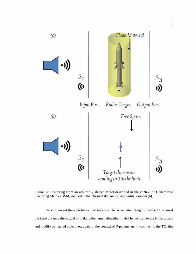
57
Figure.5.8 Scattering from an arbitrarily shaped target described in the context of Generalized
Scattering Matrix (GSM) method in the physical domain (a) and virtual domain (b).
To circumvent these problems that we encounter when attempting to use the TO to meet
the ideal but unrealistic goal of making the target altogether invisible, we turn to the FT approach
and modify our stated objectives, again in the context of S-parameters. In contrast to the TO, this

58
time we ask that S11 be small--in terms of magnitude only--but not 0, as we demanded in the case
of TO. Furthermore, we do not impose any restrictions on S12, as we did in the case of the TO
when we stipulated that the scattered fields at the output port be identically zero, so that the total
field there be just the incident field. While we concede that the performance of the FT-based
cloak or the blanket won’t be as ideal as the performance of the TO-based design would have
been if we could realize it, we certainly stand to gain considerably when we follow this strategy
since we can now obtain realizable solutions for the cloak, that are very wideband, covering the
entire frequency range of 2-18 GHz, for instance, if we so desire. Furthermore, the cloak (or
blanket) can now be very thin (only a few millimeters) and it would work for arbitrary incident
angles and polarizations as well (an FT treated radar target is shown in Fig.5.9). In short, we can
say that this strategy of following the FT-based algorithm to design the cloak enables us to
circumvent all the problems we encounter when employing the TO-based design strategy instead.
Of course, we compromise the performance of the cloak in the forward scattering direction when
we use the FT-based strategy, though that is not a problem for either monostatic or bistatic radars
that are only concerned with the backscattered fields.

59
Figure.5.9 Scattering from an FT-treated arbitrarily shaped target described in the context of
Generalized Scattering Matrix (GSM) method.

Chapter 6
Scattering Reduction for Real-World Targets
Our objective is to design wideband layered absorbers for infinite, planar, conducting ground
planes. We note that this is also the basic approach to designing coating for radar targets to render
them stealthy, regardless of their shapes. Furthermore, it is relatively easy to carry out this design
by using optimization algorithms to determine the material properties and the layer thicknesses to
reduce the reflection from the coated PEC plane below -10dB level, and over a wide frequency
band; say covering radar frequencies from 2 to 18 GHz, for example.
We now move to the second step in our design procedure, which is to adapt the blanket
designed for the infinite PEC plane to an arbitrarily shaped object. Initially we consider an object
with a smooth surface whose radius of curvature is moderate-to-large everywhere. We will
generalize the procedure in the third step, using the principles of the TO when the above
assumption regarding the smoothness of the object is not valid, as for instance when the object
has sharp edges or bumps, as a general target would in practice.
When the object has a relatively smooth geometry, we initially wrap the multilayer
absorbing blanket, which we have designed earlier for the planar surface around the PEC target
whose scattering cross-section we are attempting to reduce, and test the effectiveness of the
blanket for the new object. For a wide variety of targets we have examined, a number of which
are shown in Fig.6.1, we have found that the blanket does reduce the monostatic as well as the
bistatic radar cross-section in the “reflection” region near the surface of the object for different
angles of incidence and polarizations of the incoming wave. The results for a two-layer absorber
are shown in Figs.6.2 and 6.3 for a rectangular cylinder of finite length, which we have studied as
a test case.
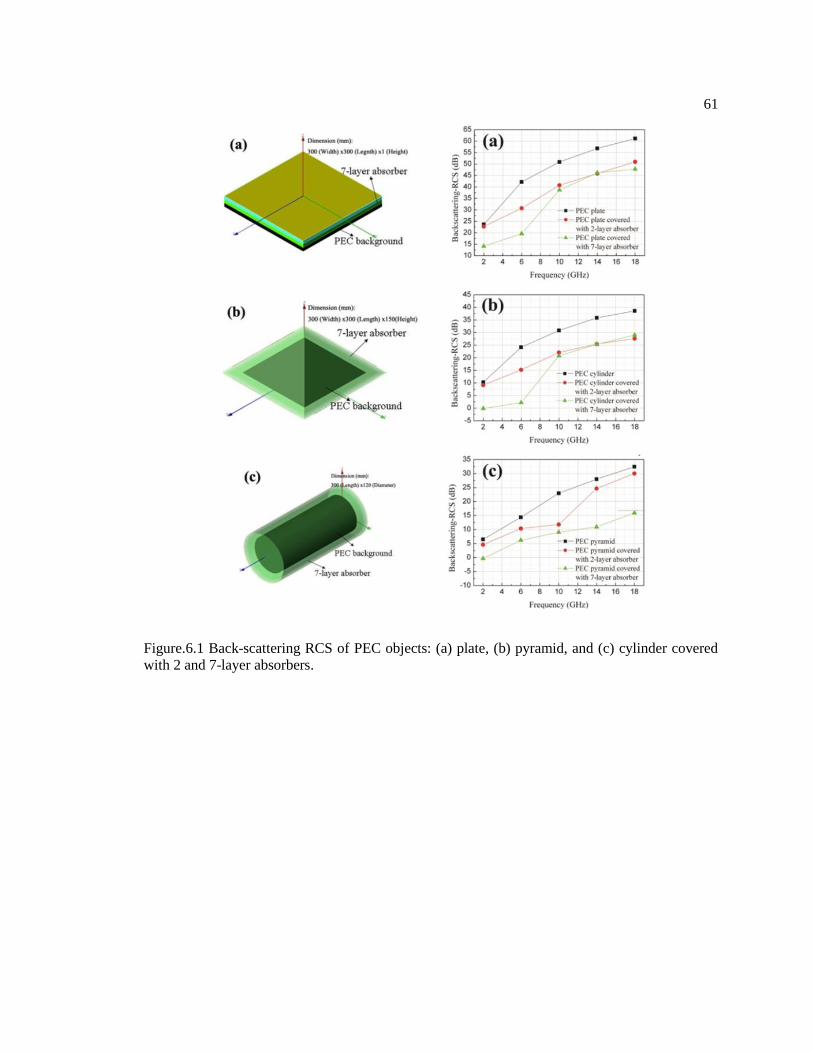
61
Figure.6.1 Back-scattering RCS of PEC objects: (a) plate, (b) pyramid, and (c) cylinder covered
with 2 and 7-layer absorbers.

62
Figure.6.2 Phase behavior of the E-field near the rectangular PEC cylinder, which is wrapped
around by an absorber blanket, normally incident on the cylinder.

63
Figure.6.3 Phase behavior of the E-field near the rectangular PEC cylinder, which is wrapped
around by an absorber blanket, for an obliquely incident plane wave.
A simple test, which is typically applied to cloak designs, is to examine the wavefront of
the total (incident+scattered) field, and see how the level of distortion of the wavefront decreases
when the scatterer is covered by the layered absorbing coating. We present the plots of these
wavefronts of the total fields for normal and oblique incidence cases for both polarizations in
Figs.6.2 and 6.3, respectively.
We observe that the object, which is a finite cylinder of height18cm, generates distorted
wavefronts owing to the contribution of the scattered field from the object, even when covered by
a two-layer blanket, designed for the infinite planar PEC object, for the nominal frequency range
of 4.6-18 GHz, with a nominal reflection coefficient of -10dB or less. However, we also note
from Figs.6.2 and 6.3 that the distortion in the phase front is relatively small once we go above

64
the low-end of the design frequency range, viz., 4.6 GHz for the planar geometry, confirming that
the planar design performs reasonably well even though we are dealing with a rectangular
cylinder now. We hasten to point out that the results presented in Fig.6.2 are not for a coating
which has been optimized for the object at hand, and we expect some compromise in the
performance of the coating. However, we can improve this performance by optimizing the
parameters of the two-layer design, specifically the relative thicknesses of the two-layer, even as
we maintain the total thickness intact. We expect the changes to be relatively minor, however,
except for the corner regions and, hence, the optimization process should be realistic as well as
numerically feasible. The above remarks are also applicable to the oblique incidence case, for
which some sample results are presented in Fig.6.3.
Figure.6.4 Target detection in conventional radar scenarios: mono-static and bi-static scheme
[39].

65
It is important to point out that the strategy for designing the absorptive coating,
presented herein, is very different from that employed for ideal traditional TO cloak, since the
latter is designed to render the (object+cloak) composite to have a zero scattering cross-section in
all directions, whereas the blanket design introduced here seeks to reduce both backscattering and
bi-static scattering scenarios but only in the reflection region, and not in the forward-scattering
direction. We hasten to point out, however, that this type of performance is perfectly well suited
for modern radar systems, symbolically depicted in Fig.6.4 above, where only the scattering in
the reflection region is of concern.
For the final step, we consider the problem of absorber design when a shape perturbation
is introduced in an object. Let us say that our modified target is the same rectangular cylinder we
just considered above, except for a bump on the top surface. The extra corners introduced by the
perturbation, be they smooth or sharp, would obviously introduce additional distortions in the
planar phase front, and potentially increase the scattering level. Our objective here is to restore
the field behavior so that it is close to that of the original object that we had prior to the
introduction of the perturbation.

66
Figure.6.5 (a) Original 2-layer absorber wrapped around a rectangular cylinder with shape
perturbation (left); (b) 2-layer absorber with TO-modified material properties around regions with
the shape perturbation (left); (c) 2-layer absorber with TO modified material properties for all
regions (left) and 2-layer absorber wrapped around a rectangular cylinder (right).
6.1 Field Transformation Algorithm, Material Modification
We now outline the procedure for the blanket design for the new object, shown on the left
in Fig.6.5, i.e., a (1), which is in the physical domain, and is a modified version of the one shown
in the right side of the same figure; i.e., Fig.6.5.(2), which corresponds to the virtual domain.
Note that unlike the cylinder example we discussed earlier, the medium in the virtual domain,
surrounding the object, is no longer free-space, as was the case shown in Fig.6.5. Note also that
the dimensions of the objects in the two domains are comparable, and are totally different from
the legacy TO-design case, in which the scale factor between the dimensions of the object in the
physical and virtual domains tends to infinity to render the target invisible.
To find the parameters of the cloak for the modified geometry in Fig.6.5, we revisit the
integral forms of Maxwell’s Equations, presented earlier in (5.2a) and (5.2b), to relate the
material parameters associated with the two systems shown in the figure. Fig.6.5.(1) shows the
physical system with locally modified medium parameters for the perturbed object, while
Fig.6.5.(2) depicts the virtual system with the original medium parameters covering the
unperturbed object. The field distribution near the perturbed object would obviously be different
from that of its unperturbed counterpart, since the perturbation introduces additional scattering to
the incoming wave. We link the change in the field with the modification in the geometry, and
then compensate it by the changing the medium parameters, which are illustrated by a slight
change of colors from the ones representing the original planar design in Fig.6.5.(1.a). Given the
specific profile of the perturbation and the simulated field distributions, the only unknowns,
namely the medium parameters, can be derived as follows:

67
(6.1a)
and
(6.1b)
where we have used scalar quantities for simplicity in Eqn.(6.1) as though the geometry under
consideration is two-dimensional, which it is in the present example, and we would need to
replace the field quantities with vectors and the material parameters with tensors for the general
3D case.
The field behaviors for the perturbed object with locally modified material parameters
can be seen from Figs.6.6 and 6.7. Fig.6.6 shows that the amplitude of the scattered E-field is
reduced, and that the phase front of the total E-field is approximately restored as well in the
reflection region. Fig.6.7 compares the amplitudes of the scattered electric fields for five different
scenarios listed in the figure.

68
Figure.6.6 Phase behavior of scattered E-field for (a) perturbed object wrapped by blanket with
original medium parameter; (b) perturbed object wrapped by blanket with locally modified
medium parameter.
Figure.6.7 Comparison of the amplitudes of electric fields scattered by different objects.
We should clarify the fact that although we are referring to this geometry as a slab, what
we are really dealing with is a wide rectangular cylinder, with a small thickness.

69
We note that the modified slab does introduce additional scattering, and that the absorber
does help reduce the same. We also note that the modified absorber improves the performance
over the initial one, but only slightly, which shows that the planar version of the cloak is not all
that inferior to the one modified for this type of geometry. Additional optimization of the
modified cloak is expected to improve the performance even further, if so desired.
Figure.6.8 Possible domain decomposition of two aircrafts: F-16 Falcon fighter jet (left) and
Predator Drone UAV (right) for scattering-reduction treatment.
For an arbitrary target, we can first decompose the geometry of the target in a manner
illustrated in Fig.6.8 into several large “blocks” that closely resemble previously investigated
objects, and wrap each part of the target with an absorber, designed by using the approach based
on shape perturbation of a related smooth object. We then follow the methodology we have
described above to determine the material parameters of the coating. It should be evident that this
is a far more realistic approach than transforming the geometries of these complex objects into an
infinitesimally small-size target, as called for by the TO algorithm for cloak designs, and
following the TO recipe corresponding to such a geometry transformation, which is bound to lead
to unrealistic and impractical material parameters and/or structural elements.

70
6.2 Field Transformation Algorithm, Thickness Modification
Modifying the permittivity and permeability parameters of the lossy materials is not the
only approach one could take to reducing the scattering from objects that have curved profiles,
especially when laboratory resources to fine-tune the material parameters in accordance with
(6.1a) and (6.1b) are not available.
Changing the composition of the absorber can be quite effective for enhancing the
absorbing performance of the coating. Fig.6.9 shows the RCS results of a PEC cylinder of radius
3cm, illuminated by a plane wave. The bi-static RCS evaluated at 10GHz, which corresponds to a
wavelength of 3cm. Various thickness compositions are analyzed to determine the one most
suited for this particular cylinder, while the total thickness of the absorber is kept unchanged at
3mm.
Fig.6.10 shows the result for another example of a PEC sphere of radius 30cm
illuminated by a plane wave. The bi-static RCS is again calculated at 10GHz. Various thickness
compositions are analyzed to determine the one that provides an optimal performance. Once
again, the total thickness of the absorber is kept unchanged at 3mm.
We note from the figures that the optimal choice for a planar absorber is not necessarily
the best one for a curved object. A moderate performance enhancement in terms of absorption can
be achieved by simply changing the thickness of the absorber, as we might expect.

71
Figure.6.9 Comparison of bi-static RCS for a long PEC cylinder coated with absorbers with
various thickness compositions, for horizontally (up) and vertically (down) polarized
illumination.
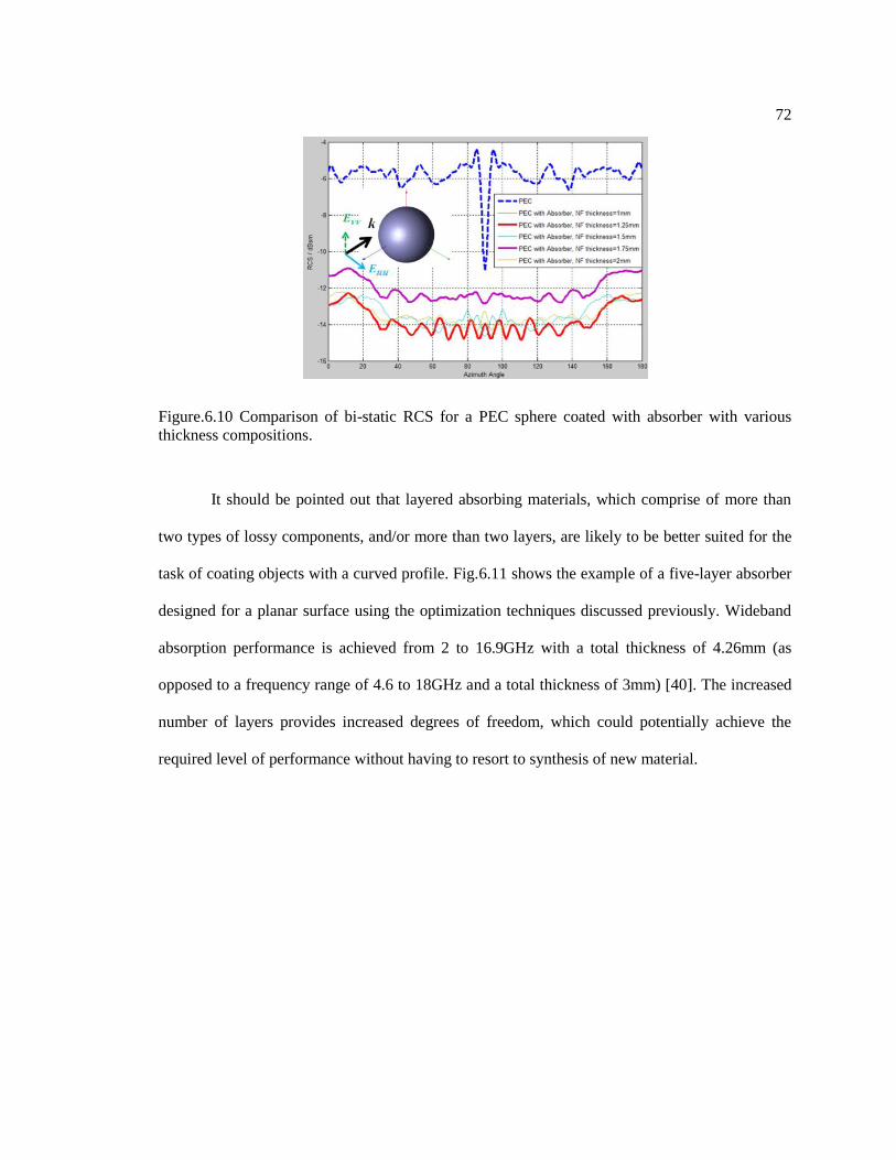
72
Figure.6.10 Comparison of bi-static RCS for a PEC sphere coated with absorber with various
thickness compositions.
It should be pointed out that layered absorbing materials, which comprise of more than
two types of lossy components, and/or more than two layers, are likely to be better suited for the
task of coating objects with a curved profile. Fig.6.11 shows the example of a five-layer absorber
designed for a planar surface using the optimization techniques discussed previously. Wideband
absorption performance is achieved from 2 to 16.9GHz with a total thickness of 4.26mm (as
opposed to a frequency range of 4.6 to 18GHz and a total thickness of 3mm) [40]. The increased
number of layers provides increased degrees of freedom, which could potentially achieve the
required level of performance without having to resort to synthesis of new material.

73
Figure.6.11 Calculated and measured reflection coefficient of a five-layer absorber [40].
Optimization techniques can still be efficiently applied to design absorptive coatings for
objects with cylindrical or spherical shapes, since the fields scattered from these canonical shapes
can be analytically expressed as functions of the material parameters and compositions of the
coatings. When the shapes of the objects are no longer canonical, as in the case in real-world
scenarios, applying optimization technique may be a time-consuming task. This is because the
forward problem, namely solving for the electric field distribution through numerical
simulation—since analytical calculation is not an option here—needs to be carried out for each
and every object, for which we are designing the absorber. It is typically computer-intensive, and

74
costly both in terms of CPU time and memory. Thus the use of powerful optimization algorithms
is highly recommended for designing these absorbers.
Fig.6.12 show the results for a PEC ellipsoid whose major and minor axes are 15cm,
3cm and 3cm respectively and which is illuminated by a plane wave with horizontal and vertical
polarizations. The bi-static RCS is calculated at 10GHz, which corresponds to a wavelength of
3cm. Two absorber compositions are analyzed to investigate the performances of these two
configurations. The first one of these uses the original absorber design for the planar structure,
while the second corresponds to the optimal thickness composition we presented in Figs.6.9 and
6.10. The total thicknesses of the two configurations are kept unchanged and it’s 3mm in both
cases.

75
Figure.6.12 Comparison of bi-static RCS for a PEC ellipsoid coated with absorber of various
thickness compositions, under horizontally (up) and vertically (down) polarized illumination.
It is evident from Fig.6.12 that the modified composition exhibits a slightly enhanced
performance for both polarizations. However, we should point out that there is no guarantee that

76
an improvement can always be achieved over that of the original planar design, and that an
optimal design for the absorber coating can indeed be derived, for a given object by simply
varying the layer thicknesses using a trial-and-error approach. An alternative technique is to
modify the material parameters, as illustrated above, which provides a more straightforward
solution, especially for geometries shaped like the ellipsoids.
6.3 Practical Applications
Reduction of RFI, another important application for the absorber-wrapping is to mitigate
the problem of antenna blockage in a shared-platform environment, as shown in Fig.6.13, in
which the introduction of the aggressor antenna can raise the far-end sidelobe levels of the
parabolic dish significantly. To mitigate this effect, we can wrap the monopole by using a
multilayer absorber optimized for a planar geometry, as we have done in the past, or we can
optimize the layer thicknesses and material parameter for the circular cylinder geometry.
Alternatively, we can use a conducting saucer-like structure wrapped around the monopole, as
proposed in [41-43]. Fig.6.14 shows the model used to construct the alternative cloak with the
monopole as the cloaked target. Fig.6.15 shows the far field patterns of a parabolic dish
antenna—the victim antenna—when a monopole, which is the aggressor antenna, is placed in the
vicinity of the dish. The patterns of the dish/monopole composite are also included in the figure
for two treatment plans applied to the aggressor antenna. We note that the introduction of the
absorber treatment reduces the sidelobe levels of the dish antenna, as compared to the case for the
far-end antenna combination without the treatment.
However, we also note that an elaborate cloak design, shown in Fig.6.14, isn’t really
needed, and same level of performance can be achieved with a thin absorber type of coating.
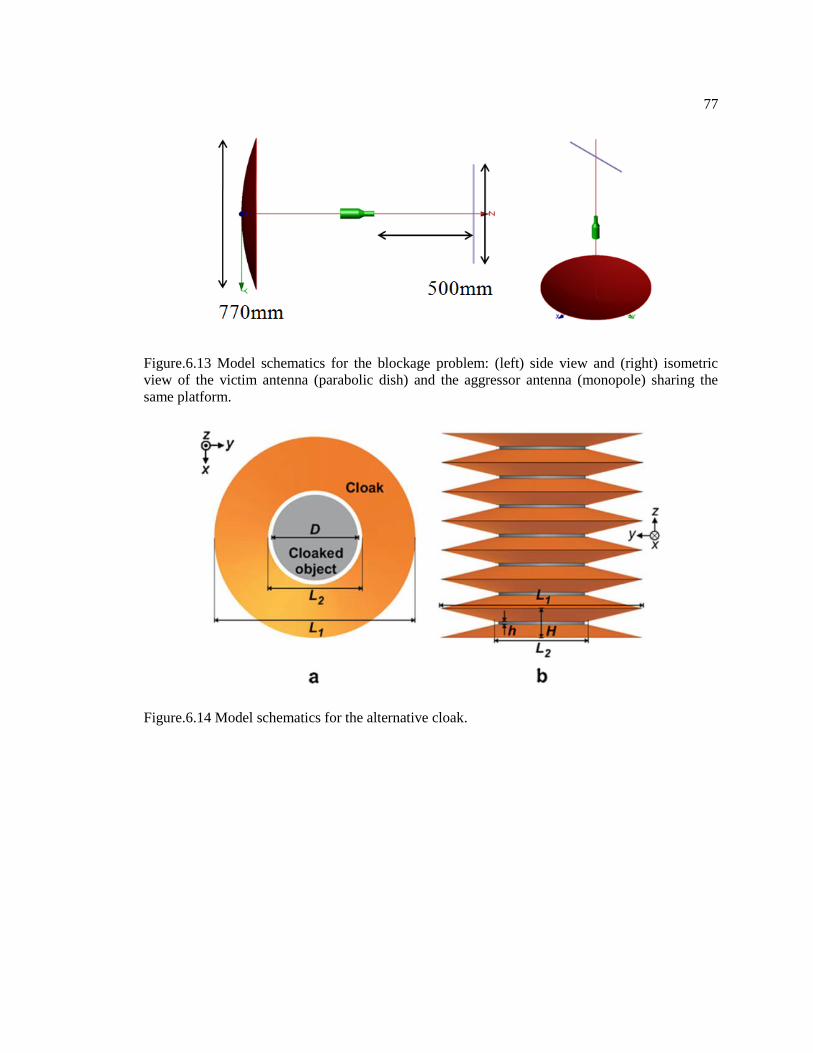
77
Figure.6.13 Model schematics for the blockage problem: (left) side view and (right) isometric
view of the victim antenna (parabolic dish) and the aggressor antenna (monopole) sharing the
same platform.
Figure.6.14 Model schematics for the alternative cloak.

78
Figure.6.15 Radiation patterns for the antenna blockage problem: (blue) dish antenna, (green)
dish antenna and the monopole antenna in the vicinity and (red) dish antenna with absorber-
treated monopole antenna.
Recent advances in material engineering and research in graphene-based absorbing
materials also broadens the choice of the materials used for the absorber designs discussed in this
paper. Graphene-based absorbing materials generate sufficient level of magnetic loss without the
need to introduce magnetic elements such as Co, Fe and Ni. These new materials also have the
advantage of being lightweight, and thin, that are highly desired attributes for airborne
applications. There have been reported cases of achieving below -70dB reflection level shielding

79
with 2.09mm of graphene nanoplatelet-synthesized material [43], as well as below -20dB
reflection level over the entire 4.5-18GHz with 8mm of multilayered carbon nanotube fabric [44].
The performance of the absorbers can also be enhanced by introducing FSS-type
structures within the layers, which add virtually no extra thickness to the composite structure. The
FSS structures can be tailored to enhance the absorption in target frequency bands [16] or to
broaden the working bandwidth [44] of the initial layered absorber.

Chapter 7
Suggestions for Future Works
Several directions can be explored in the future that could further complement the works
in this dissertation.
First, all the FSS type absorbers investigated in this dissertation have been strictly
periodic. Aperiodicity can be introduced in the periodic elements to further enhance the
bandwidth performance of the absorber screen. Statistical analysis can be applied to an absorber
screen with a large enough number of elements so that the absorption level at specific frequency
bands can be tailored (to an extend) and a systematic approach can be developed to determine the
relationship between the absorbing performance and the size as well as the number of a single
element.
Secondly, the algorithm developed in this dissertation for determining the modified
material parameter for objects with local shape/structural perturbations works well when the
shape perturbation does not have a small radius of curvature, i.e., no sharp corners. It is likely that
the calculated material parameter will vary greatly in the vicinity of a sharp corner, This means
these results might not fall into the range of achievable material parameters due to the constraints
of the synthesizing process. A systematic approach of realizing artificial material with desired
material parameter, e.g. Dial-a Dielectric (DaD) approach, would greatly increase the flexibility
of the algorithm.
The wideband absorbers discussed in this dissertation have been designed to have
continuous absorption performance. It would be desirable for antennas on some airborne vehicles
to be functional in their operational frequency and to have low scattering levels outside the

81
working frequency window. Band-notch periodic structures can be investigated to meet the
requirements for this application.

Bibliography
[1] W. W. Salisbury, “Absorbent body for electromagnetic waves,” US Patent 2599944, June 10,
1952.
[2] E. F. Knott, J. Shaeffer, and M. Tuley, Radar cross section, SciTech Publishing, 2004.
[3] W. Dallenbach, “Transmission and/or the reception of electromagnetic waves,” US Patent
2297202 A, Sep 29, 1942
[4] H. Guo, Y. Zhan, Z. Chen, F. Meng, J. Wei, and X. Liu, “Decoration of basalt fibers with
hybrid Fe3O4 microspheres and their microwave absorption application in bisphthalonitrile
composites,” Journal of Materials Chemistry A, 1(6), 2286-2296 (2013).
[5] B. Wang, J. Zhang, T. Wang, L. Qiao, and F. Li, “Synthesis and enhanced microwave
absorption properties of Ni@Ni2O3 core–shell particles,” Journal of Alloys and Compounds, 567,
21-25 (2013).
[6] X. Yan and D. Xue, “Fabrication and Microwave Absorption Properties of Fe0.64Ni0.36-
NiFe2O4 Nanocomposite,” Nano-Micro Lett. 4 (3), 176-179 (2012).
[7] X. Li, C. Wang, X. Han, and Y. Wu, “Surfactant-free synthesis and electromagnetic properties
of Co–Ni–B composite particles,” Materials Science and Engineering: B, 178(3), 211-217
(2013).
[8] B. Chambers, and A. Tennant, “Design of wideband Jaumann radar absorbers with
optimum oblique incidence performance,” Electronics Letters 30.18 (1994): 1530-1532.
[9] A. Kazemzadeh, “Nonmagnetic ultrawideband absorber with optimal thickness,” Antennas
and Propagation, IEEE Transactions on, 59(1), 135-140 (2011).
[10] H. Tao, C. M. Bingham, A. C. Strikwerda, D. Pilon, D. Shrekenhamer, N. I. Landy and R. D.
Averitt, “Highly flexible wide angle of incidence terahertz metamaterial absorber: Design,
fabrication, and characterization,” physical review B, 78(24), 241103 (2008).
[11] G. H. Yang, X. X. Liu, Y. L. Lv, J. H. Fu, Q. Wu, and X. Gu, “Broadband polarization-
insensitive absorber based on gradient structure metamaterial,” Journal of Applied Physics,
115(17), 17E523 (2014).
[12] R. F. Harrington, Time-Harmonic Electromagnetic Fields, McGraw-Hill, New York, 1961.

83
[13] C. A. Balanis, Advanced Engineering Electromagnetics, John Wiley & Sons, New York,
1989.
[14] Y. Zhou, R. Mittra, “Performance Enhancement of RF Absorbers by Using Resistively-
Loaded Periodic Screens,” Antennas and Propagation Society International Symposium (APS-
URSI), IEEE, July 2012.
[15] Y. Shang, Z. Shen, S. Xiao, “On the Design of Single-Layer Circuit Analog Absorber Using
Double-Square-Loop Array,” Antennas and Propagation, IEEE Transactions on , vol. PP, no.99,
pp.1, 2013.
[16] Y. Zhou, R. Mittra, “Performance enhancement of a dual-loop FSS-based absorber,”
Antennas and Propagation Society International Symposium (APS-URSI), IEEE, pp.2062-2063,
6-11 July 2014.
[17] Y. X. Gong, L. Zhen, J. T. Jiang, C. Y. Xu, W. Z. Shao, “Synthesis and microwave
electromagnetic properties of CoFe alloy nanoflakes prepared with hydrogen-thermal reduction
method,” J. Appl. Phys. 106, 064302 (2009).
[18] L. Zhen, Y. X. Gong, J. T. Jiang, C. Y. Xu, W. Z. Shao, P. Liu, J. Tang, “Synthesis of
CoFe/Al2O3 composite nanoparticles as the impedance matching layer of wideband multilayer
absorber,” J. Appl. Phys. 109, 07A332 (2011).
[19] J. B. Pendry, D. Schurig and D. R. Smith, “Controlling electromagnetic fields,” Science 312,
1780–1782 (2006).
[20] U. Leonhardt, “Optical conformal mapping,” Science 312, 1777–1780 (2006).
[21] R.Yang, W. Tang, and Y.Hao, “A broadband zone plate lens from transformation optics,”
Optics Express 19.13 (2011): 12348-12355.
[22] C. Argyropoulos, E. Kallos, Y. Zhao, and Y. Hao, “Manipulating the loss in electromagnetic
cloaks for perfect wave absorption,” Opt. Express vol. 17, pp. 8467–8475, 2009.
[23] C. Argyropoulos, E. Kallos, and Y. Hao, “FDTD analysis of the optical black hole,” J. Opt.
Soc. Am. B vol. 27, pp. 2020–2025, 20110.
[24] D.-H. Kwon, and D. H. Werner, “Transformation electromagnetics: an overview of the
theory and applications,” Antennas and Propagation Magazine, IEEE 52.1 (2010): 24-46.
[25] T. Ergin, N. Stenger, P. Brenner, J.B. Pendry, and M. Wegener, “Three-dimensional
invisibility cloak at optical wavelengths,” Science 328, 337–339 (2010).
[26] H. Y. Chen,and C. T. Chan, “Transformation media that rotate electromagnetic fields,” Appl.
Phys. Lett. 90, 241105 (2007).

84
[27] U. Leonhardt, and T. G. Philbin, “Transformation optics and the geometry of light,” Prog.
Opt. 53, 69–152 (2009).
[28] H. Chen, C. T. Chan, and P. Sheng, “Transformation optics and metamaterials,” Nature
Mater. 9, 387–396 (2010).
[29] P. A. Huidobro, M. L. Nesterov, L. Martı´n-Moreno, and F. J. Garcı´a-Vidal,
“Transformation optics for plasmonics,” NanoLett. 10, 1985–1990 (2010).
[30] B. Edwards, A. Alu, M. G. Silveirinha and N. Engheta, “Experimental verification of
plasmonic cloaking at microwave frequencies with metamaterials,” Phys. Rev. Lett. 103 153901
(2009).
[31] A. Alu, and N. Engheta, “Achieving transparency with plasmonic and metamaterial
coatings,” Phys. Rev. E 72 016623 2005.
[32] Y. Luo, J. Zhang, H. Chen, S. Xi and B.-I. Wu, “Cylindrical cloak with axial
permittivity/permeability spatially invariant,” Appl. Phys. Lett. 93 033504 2008.
[33] A. Alu, A. D. Yaghijan, R. A. Shore and M. G. Silveirinha, “Causality relations in the
homogenization of metamaterials,” Phys. Rev. B 84 054305 2011.
[34] Q. Cheng, T. Cui, W. Jiang and B. Cai, “An omnidirectional electromagnetic absorber made
of metamaterials,” New J. Phys. 12 063006 2010.
[35] T. Zentgraf, Y. Liu, M. H. Mikkelsen, J. Valentine and X. Zhang, “Plasmonic Luneburg and
Eaton lenses,” Nature Nano 6 151–5 2011.
[36] D. Schurig, J. B. Pendry, and D. R. Smith, “Calculation of material properties and ray tracing
in transformation media,” Opt. Express. 14, 9794–9804 (2006).
[37] D. Schurig, J. J. Mock, B. J. Justice, S. A. Cummer, J. B. Pendry, A. F. Starr and D. R.
Smith, “Metamaterial electromagnetic cloak at microwave frequencies,” Science 314, 977–980
(2006).
[38] E. Martini, G. Carli, and S. Maci, “A domain decomposition method based on a generalized
scattering matrix formalism and a complex source expansion,” Progress In Electromagnetics
Research B, Vol. 19, 445–473, 2010.
[39] R. Mittra, Y. Zhou, “Design of Absorptive Coatings for Arbitrarily Shaped Targets for
Reduction of Radar Cross Section (RCS) Using an Alternative to the Transformation Optics (to)
Algorithm,” (Invited Paper) Progress In Electromagnetics Research, Vol. 147, 153-170, 2014.
[40] Y. Qing, W. Zhou, S. Huang, Z. Huang, F. Luo, & D. Zhu, “Evolution of double magnetic
resonance behavior and electromagnetic properties of flake carbonyl iron and multi-walled
carbon nanotubes filled epoxy-silicone,” Journal of Alloys and Compounds, 583, 471-475 (2014).

85
[41] S. Tretyakov, P. Alitalo, O. Luukkonen, C. Simovski, “Broadband electromagnetic cloaking
of long cylindrical objects,” Phys. Rev. Lett., 2009, 103, 103905.
[42] P. Alitalo and S. A. Tretyakov, “Electromagnetic cloaking of strongly scattering cylindrical
objects by a volumetric structure composed of conical metal plates,” Phys. Rev. B 82, 245111
(2010).
[43] J. Vehmas, P. Alitalo, S.A. Tretyakov, “Experimental demonstration of antenna blockage
reduction with a transmission-line cloak,” Microwaves, Antennas & Propagation, IET, vol.6,
no.7, pp.830-834, 2012.
[44] G. De Bellis, I.M. De Rosa, A. Dinescu, M.S. Sarto, A. Tamburrano, “Electromagnetic
Absorbing Nanocomposites Including Carbon Fibers, Nanotubes and Graphene Nanoplatelets,”
International Symposium on Electromagnetic Compatibility (EMC), 2010 IEEE. IEEE, 2010.
[45] R. A. Tellakula, V. K. Varadan, T. C. Shami and G. N. Mathur, “Carbon fiber and nanotube
based composites with polypyrrole fabric as electromagnetic absorbers,” Smart Mater. Struct. 13
(2004) 1040–1044.

VITA
Yuda Zhou
Yuda Zhou was born on 6th of May 1986, the first day of summer in the Chinese lunisolar
Calendar, in the City of Daqing, Heilongjiang Province, China. That was also the same day 21
years after the death of essayist Zhou Zuoren and 130 years after the birth of Sigmund Freud, not
that that's important in any way. He graduated from Daqing Shiyan High School in 2004. He
obtained his Bachelor of Science degree in the Department of Communications Engineering from
Harbin Institute of Technology, Harbin, Heilongjiang, China in 2008. He joined the Department
of Electrical Engineering at the Pennsylvania State University, University Park, USA in August
of 2008 where he continued as a graduate research assistant. He obtained his Ph.D. in August
2015. His research interests include RF and electromagnetic absorbers, Frequency Selective
Surfaces (FSSs), antenna design/measurement and practical applications of electromagnetic
scattering reduction.