a study of flow inside a centrifugal pump: high performance
TRANSCRIPT

A Study of Flow inside a Centrifugal Pump: HighPerformance Numerical Simulations Using GPUcardsAlessandro Nocente1*, Tufan Arslan2, Daniel Jasinski3, Torbjørn K. Nielsen1
SYM
POSI
A
ON ROTATING MACHIN
ERY
ISROMAC 2016
InternationalSymposium on
TransportPhenomena andDynamics ofRotatingMachinery
Hawaii, Honolulu
April 10-15, 2016
AbstractThe present work reviews calculations of a steady three-dimensional (3D) flow past a centrifugalpump with its diffuser channels using different hardwares. The open source CFD softwareOpenFOAM has been ported to the GPU platform with double precision. The performanceof a high-end GPU was reported. The considered computational domain is one of the threestages, since each has exactly the same design. In this work, simulations were carried out at thebest efficiency point (BEP) for single phase flow with four different turbulence models. Theresults were compared with the performance report from the manufacturer. Only the realizablek-ε turbulence model has been taken into account for performance tests. The comparisons atBEP showed that integral quantity based results were not sensibly influenced by the turbulencemodel and the steady state simulations demonstrated to be a good approximation of the LDVdata, always containing the error within an acceptable limit. The ability of solving numericalproblems faster makes GPU hardware attractive to be used for further investigations which willinvolve two-phase flow studies on the same pump.
KeywordsGPU — OpenFOAM — CFD — Centrifugal Pump — Vaned Diffuser — Produced Water1Department of Energy and Process Engineering, NTNU, Trondheim, Norway2IT Division, NTNU, Trondheim, Norway3Simflow, Warsaw, Poland
*Corresponding author: [email protected]
INTRODUCTION
Computational Fluid Dynamics (CFD) simulations arenowadays very accurate in predicting flow conditions inturbomachinery. The development and diffusion of CFDcodes and the growth of available computer power havehugely increased the usage of CFD in turbomachinery[1],[2]. It is less expensive and less time consuming thanan experimental investigation, and allows testing newparts design before the actual realization of a prototype.Given a certain level of accuracy and confidence of thesimulation results, the computational time has a greatimportance. Less time-consuming simulations are alwayspreferable. GPU cards can reduce the computationaltime significantly. This reduction free resources whichcan be used to investigate deeper the internal flow bymean of a more accurate simulations (i.e. a finer mesh forthe same domain). In this paper, we worked on a multi-stage centrifugal pump with closed impeller and a vaneddiffuser specifically designed for offshore produced watertreatment. It processes a dispersed phase flow whichrequires the least possible shear and a proper internalcirculation [3] in order to avoid the use of chemicals [4].Many researchers have used CFD for investigation of flowinside centrifugal pumps, most of them concentratingon pumps with volute casing. Shukla and Kshirsagar[5] calculated the internal flow using k-ε and k-ω tur-bulence models. Cheah et al. [6] concentrated on the
flow inside the impeller and Bacharoudis et al. [7] re-alized a parametrical study on how performances areaffected by different impellers. Shah et al. [8] carriedover calculations on different operating points using bothRNG k-ε and SST k-ω turbulence models. Among theresearchers who worked specifically on vaned diffuser cen-trifugal pumps, Muggli et al. [9] applied a Navier-Stokescode with a standard k-ε model to the study of the flowin a vaned diffuser of a high loaded centrifugal pump.Feng at al. [10] investigated the flow and the pressurefluctuations on the impeller blade and the vaned surfaceof a diffuser. Zhou et al. [11] conducted a numericalinvestigation on unsteady flow field in a multistage cen-trifugal pump with focus on the pressure fluctuationswhile Pei et al. [12] on a high power centrifugal diffuserpump for residual heat removal. Other researchers per-formed a comparison between the results obtained withCFD and the experimental data. Sinha and Katz [13]used PIV technique, Feng et al. [14] used Laser DopplerVelocimetry (LDV) and Pedersen et al. [15] applied bothexperimental techniques.
The present study focuses on the characterizationof the flow in the diffuser channels of a multistage cen-trifugal pump. One characterization of the flow passedthe same multistage pump has already been achieved inprevious works [16], [17]. The steady state and transientstate simulation at the same working conditions have

A Study of Flow inside a Centrifugal Pump: High Performance Numerical Simulations Using GPU cards — 2/7
been carried on using commercial Ansys Fluent software.In this work, the open-source software RapidCFD [18]has been used. The code is based on OpenFOAM [19]solvers which are running on GPU cards rather thanCPUs. The performance gain of GPUs over CPUs hasbeen studied for the simulated case which is a steadythree dimensional (3D) flow past the diffuser channels ofa centrifugal pump.
1. NUMERICAL MODEL
The pump investigated in this work is a prototype re-alized for Typhonix AS. It is a three-stage end suctioncentrifugal pump for produced water. The computationaldomain consists of the inlet pipe, the first stage impellerand the first stage stator. After passing the stator, thefluid is addressed to the following stage by mean of re-turn vanes. This part of the machine does not influencethe performance significantly, therefore is not includedin this work to save computational time.
Figure 1. Computational Domain [17]
In Table 1, the main geometrical characteristics of theimpeller and diffuser are listed along with head, flow rateand rotational speed at the operating point. Figure 1shows the 3D computational domain. The computationalgrid is structured along the pump axis direction withhexahedral cells in the diffuser domain. The grid hasno size refinement along the walls since we believe thatthe resolution were fine enough to take into account thewall effects on the flow. After the simulations, a checkconfirmed this assumption by showing that y+ is in the
ImpellerNumber of blades Zi 6Inlet diameter DRi 100 mmOutlet diameter DRo 264 mmOutlet height hRo 13 mm
DiffuserNumber of blades Zd 10Inlet diameter DSi 270 mmOutlet diameter DSo 478 mmOutlet height hSo 18 mm
Design Operating PointFlow rate QBEP 60 m3/hDelivered head HBEP 62 mRotational speed nBEP 1480 rpm
Table 1. Pump Specification [17]
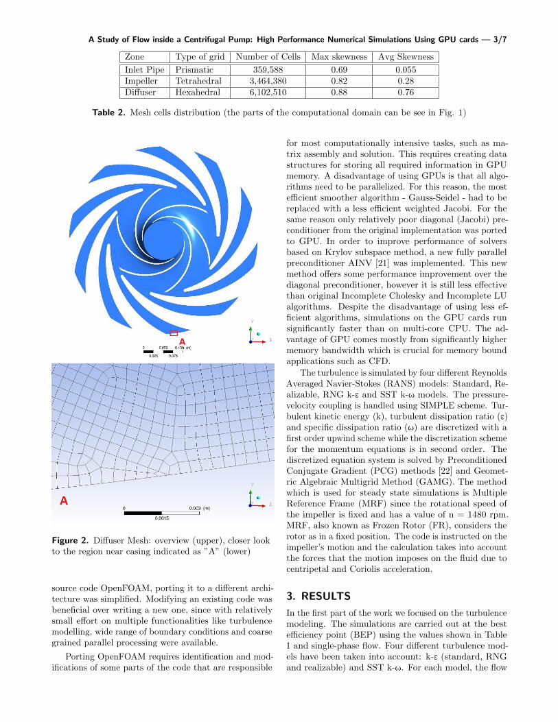
range 30 < y+ < 300. This allows us to use proper wallmodelling in the calculation of the turbulence which willbe mentioned in next section. The entire computationaldomain is shown on the left side of Fig. 2. The lowerside of the figure shows a closer look to a small region ofthe diffuser mesh which is indicated as “A”.
Due to the complicated shape of the impeller vanes,the impeller grid is unstructured with tetrahedral cells.The total number of cells is about 10 millions (9,926,478)cells. The distribution of the cells in the different zonesof the computational domain is summarized in Table 2.The mesh quality was checked on cell skewness which isdefined as the difference between the shape of the celland the shape of an equilateral cell of equivalent volume.The optimal value for skewness is 0. A maximum valuegreater than 0.95 may lead to convergence difficulties.The average and maximum values of mesh skewness foreach mesh zone is shown in Table 2. The convergencebehaviour will be mentioned in Section 4.
No-slip wall condition has been specified for all thewall boundaries such as pipes, hubs, shrouds, blades plusthe upper and lower wall of both impeller and diffuser.At the inlet of the pipe, mass flow boundary condition isimposed. Zero pressure is imposed at the diffuser outletin order to calculate the stage head. Turbulent intensityis considered moderate and it is imposed 5% at the inlet.
2. THE SOLVER RUNNING ON GPU
RapidCFD is a CUDA-ported version of a Finite VolumeMethod based code OpenFOAM, that runs all simulationstages on Graphic Processing Units (GPU). Running en-tire simulation on the GPU has a significant performanceadvantage over commonly used [20] GPU acceleration ofsolvers for linear equation systems. With the full accel-eration, there is no need for constant memory copyingbetween CPU and GPU memory space which is a hugebottleneck that significantly decreases overall simulationspeed. Due to a very good design and modularity of open
A Study of Flow inside a Centrifugal Pump: High Performance Numerical Simulations Using GPU cards — 3/7
Zone Type of grid Number of Cells Max skewness Avg Skewness
Inlet Pipe Prismatic 359,588 0.69 0.055Impeller Tetrahedral 3,464,380 0.82 0.28Diffuser Hexahedral 6,102,510 0.88 0.76
Table 2. Mesh cells distribution (the parts of the computational domain can be see in Fig. 1)
Figure 2. Diffuser Mesh: overview (upper), closer lookto the region near casing indicated as ”A” (lower)
source code OpenFOAM, porting it to a different archi-tecture was simplified. Modifying an existing code wasbeneficial over writing a new one, since with relativelysmall effort on multiple functionalities like turbulencemodelling, wide range of boundary conditions and coarsegrained parallel processing were available.
Porting OpenFOAM requires identification and mod-ifications of some parts of the code that are responsible
for most computationally intensive tasks, such as ma-trix assembly and solution. This requires creating datastructures for storing all required information in GPUmemory. A disadvantage of using GPUs is that all algo-rithms need to be parallelized. For this reason, the mostefficient smoother algorithm - Gauss-Seidel - had to bereplaced with a less efficient weighted Jacobi. For thesame reason only relatively poor diagonal (Jacobi) pre-conditioner from the original implementation was portedto GPU. In order to improve performance of solversbased on Krylov subspace method, a new fully parallelpreconditioner AINV [21] was implemented. This newmethod offers some performance improvement over thediagonal preconditioner, however it is still less effectivethan original Incomplete Cholesky and Incomplete LUalgorithms. Despite the disadvantage of using less ef-ficient algorithms, simulations on the GPU cards runsignificantly faster than on multi-core CPU. The ad-vantage of GPU comes mostly from significantly highermemory bandwidth which is crucial for memory boundapplications such as CFD.
The turbulence is simulated by four different ReynoldsAveraged Navier-Stokes (RANS) models: Standard, Re-alizable, RNG k-ε and SST k-ω models. The pressure-velocity coupling is handled using SIMPLE scheme. Tur-bulent kinetic energy (k), turbulent dissipation ratio (ε)and specific dissipation ratio (ω) are discretized with afirst order upwind scheme while the discretization schemefor the momentum equations is in second order. Thediscretized equation system is solved by PreconditionedConjugate Gradient (PCG) methods [22] and Geomet-ric Algebraic Multigrid Method (GAMG). The methodwhich is used for steady state simulations is MultipleReference Frame (MRF) since the rotational speed ofthe impeller is fixed and has a value of n = 1480 rpm.MRF, also known as Frozen Rotor (FR), considers therotor as in a fixed position. The code is instructed on theimpeller’s motion and the calculation takes into accountthe forces that the motion imposes on the fluid due tocentripetal and Coriolis acceleration.
3. RESULTS
In the first part of the work we focused on the turbulencemodeling. The simulations are carried out at the bestefficiency point (BEP) using the values shown in Table1 and single-phase flow. Four different turbulence mod-els have been taken into account: k-ε (standard, RNGand realizable) and SST k-ω. For each model, the flow

A Study of Flow inside a Centrifugal Pump: High Performance Numerical Simulations Using GPU cards — 4/7
Figure 3. Mean velocity magnitudes in mid-section of the diffuser: CFD (left), LDV (right) for BEP (60 m3/h)with Realizable k-ε model
conditions have been calculated in steady state at bestefficiency point (BEP). The resultant integral quantities(head, torque and efficiency) for each simulation havebeen compared to the data provided by the prototypemanufacturer. Manufacturer data refers to a three stagepump, but for the comparison we assume the hypothesis,widely used in the study of multistage pumps, that eachof the three stage of the pump provide for 1/3 of thetorque and the head.
The return vane between consecutive stages is notpart of the calculation because of its computational de-mand, and the results demonstrate that they have negligi-ble influence on head or efficiency. The return vanes havein fact no role in transferring or transforming energy.
In Table 3, head, torque and efficiency for each con-sidered turbulence models are compared with the man-ufacturer’s data. Data indicated as ”Test” are to bereferred to the commissioning test carried out from themanufacturer on the whole pump. The differences in thehead is acceptable.
Concerning the internal flow in the diffuser channel,both the pressure and absolute velocity fields have beeninvestigated. The overall ranges of velocities and pres-sures are the same, the flow structures are not affectedby significant variation in the different turbulence mod-els. In addition, there is not evident flow detachment.This means that the pump prototype is substantiallywell designed and explains the similarity of results indifferent turbulence models. According to these result, itis possible to state that for this simulation, the choice ofturbulence model does not significantly affect the results.The comparison at this discharge level shows that the
steady state model can approximate within 4-7% errorthe real flow characteristics as seen in Table 3. Thesame consideration can be done for the torque and theefficiency.
Because of the small influence of the turbulent modelchoice on this particular case, we decided to use only oneof the turbulence models for the calculations. Althoughthe standard k-ε model gave slightly more close resultsto the experimental data, the realizable k-ε model hasbeen chosen because its robustness. In the meanwhile,an experimental campaign of Laser Doppler Velocime-try (LDV) measurements has been carried out in theWaterpower laboratory at NTNU, Trondheim. An ex-perimental water loop has been designed and realizedusing a single stage of the pump. A special casing withplexyglass inspection window has been designed to guar-antee an optical access for the laser probes. The velocitymeasurements have been repeated several times measur-ing on very fine grid of points. Hence it was possible todraw a quite accurate contour of the velocity along themid plane of the diffuser. This contour is compared to a2D contour obtained from the simulations in Fig. 3.
4. GPU PERFORMANCE
In the GPU cluster we have used, CPUs are Intel XeonE5-2670 with 8 cores working at 2.60 GHz. The graphicscards are NVIDIA GeForce Titan X with 3072 CUDAcores and 12 GB GDDR5 memory. At each node, thereare two cards installed via PCI Express connection andtwo CPUs. In this work, a single node is used. The clustersystems used in this work are Vilje [23] and Kongull

A Study of Flow inside a Centrifugal Pump: High Performance Numerical Simulations Using GPU cards — 5/7
Head [m] Torque [Nm] Efficiency [%]Standard k-ε 21.8 32.7 70RNG k-ε 22.6 32.5 73Realizable k-ε 21.2 30.2 74SST k-ω 20.7 29.5 74TEST 21.0 32.6 66.7RATED 20.3 31.9 69.0
Table 3. Integral quantities values for the different turbulence models
located in Trondheim, Norway and Abel [24] which islocated in Oslo, Norway.
Figure 4. Residuals in the simulations (GPU)
Figure 5. Residuals in the simulations (CPU)
The performance tests were made by RapidCFD’s tur-bulent steady state solver: simpleFoam. Both GeometricAlgebraic Multigrid solver (GAMG) and PreconditionedConjugate Gradient (PCG) solving for pressure equationwere tested on both CPU and GPU in double precision.
Solving velocity and turbulent quantities is not havinga significant role in computational effort therefore thesolution method of pressure equation was focused more.As mentioned in the previous section, available precon-ditioner of PCG solver is AINV in RapidCFD (GPU)while standard OpenFoam solver (CPU) was using Di-agonal Incomplete-Cholesky (DIC) which is the fastestone available. GAMG is using Gauss-Seidel smootheralgorithm in OpenFOAM and Jacobi algorithm was usedin RapidCFD. In the tests, simulations ran for 2 hourswith several number of time steps (from 100 to 1000based on the performance) and the first time step wasdiscarded in the total wall time calculations. The con-vergence behaviour of the solver in the GPU simulationscan be seen in Figure 4. As seen in Figure 5 the residualsare not fluctuating in CPU simulations. however thevalues for both simulations are smaller than 1e-5 for allequations.
The performance (calculated from wall clock time periteration) for the GPU card (2 cards) over the 2 CPUunit (16 cores) is shown in Fig. 6. The GPU providedspeed-up for PCG solver for two card is 3.4x which canbe seen in Fig. 6. However, PCG is very slow comparedto the GAMG solver for both GPU and CPU generally.In our case, GAMG shows superior performance overPCG as seen in Fig. 6. At the same time, GPU gives2.3x speed up for GAMG solver. However, GAMG solverrequires larger memory than PCG, therefore, our casecould not be handled at a single GPU card when GAMGwas used. The tests were performed with two cards byusing MPI for data communication between the cards.The results were compared to the performance with 2CPUs for both PCG and GAMG solvers.
5. CONCLUSIONS AND FUTURE WORK
This work aims to show that the new hardware plat-forms can be used for simulations at the industrial leveland to demonstrate their importance for the future ofCFD. The results demonstrates that OpenFOAM basedRapidCFD shows promising speed up (around 2.6-3.5)with NVIDIA’s GeForce Titan X graphics cards versusIntel Xeon E5-2670 CPU units for calculations in doubleprecision. It brings significant advantage for simulatingthe flow because of the faster convergence in solving thepressure equation. However, the memory of the GPU

A Study of Flow inside a Centrifugal Pump: High Performance Numerical Simulations Using GPU cards — 6/7
Figure 6. Performance of GPU versus CPU with different matrix solvers
cards is limited and it can be a bottleneck for simulatinglarger cases. In this work we have used single nodes with2 GPU cards and 2 CPUs. Using multiple nodes andbenchmarking scalability of the multi-GPU simulationsis a worthy future work.
As mentioned before in the results section, we canaffirm that the simulation results are not influenced bythe turbulence model used. The accuracy of the steadysimulations has been evaluated in comparison with thetest results provided by manufacturer. The difference inpredictions of head tends to be small around the BEP,which is the design condition. As a future development,the steady state simulations will be used to simulate theflow in the pump at different load conditions and diffuserdesign. A dispersed phase flow will also be simulatedin order study the behaviour of a dispersed phase inthe diffuser for different load conditions and differentdispersed phase density.
ACKNOWLEDGMENTS
The authors thank to NTNU via NOTUR (The Norwe-gian Metacenter for computational Science) for support-ing the computing time.
NOMENCLATURE
ε Turbulence dissipation rate [m2/s3]
η Efficiency [rpm]
ω Specific turbulence dissipation rate [m2/s2]
AINV Approximate Inverse
BEP Best Efficiency Point
DRi Rotor inlet diameter [mm]
DRo Rotor outlet diameter [mm]
DSi Stator inlet diameter [mm]
DSo Stator outlet diameter [mm]
DIC Diagonal Incomplete-Cholesky
FR Frozen Rotor
GAMG Geometric Algebraic Multigrid solver
H pump Head [m]
hRo Rotor outlet height [mm]
hSo Stator outlet height [mm]
k Turbulence kinetic energy [m2/s2]
LDV Laser Doppler Velocimetry
MRF Multiple Reference Frame
n Rotational speed [rpm]
PCG Preconditioned Conjugate Gradient
Q Flow rate [m3/h]
T Torque [Nm]
y+ Dimensionless wall distance
Zd Number of diffuser blades
Zi Number of rotor blades

A Study of Flow inside a Centrifugal Pump: High Performance Numerical Simulations Using GPU cards — 7/7
REFERENCES
[1] Eric Dick, Jan Vierendeels, Sven Serbruyns, andJohn Vande Voorde. Performance prediction ofcentrifugal pumps with cfd-tools. Task quarterly,5(4):579–594, 2001.
[2] John Vande Voorde, Erik Dick, Jan Vierendeels, andS Serbruyns. Performance prediction of centrifugalpumps with steady and unsteady cfd-methods. In4th International on Advances in Fluid Mechanics,pages 559–568. WIT Press, 2002.
[3] Mark J. van der Zande and W.M.G.T. van denBroek. Break-up of oil droplets in the productionsystem. page 7pp, Houston, TX, USA, 1998. ASME,Fairfield, NJ, United States.
[4] Johan Sjoblom, Narve Aske, Inge Harald Auflem,Øystein Brandal, Trond Erik Havre, Øystein Sæther,Arild Westvik, Einar Eng Johnsen, and Harald Kal-levik. Our current understanding of water-in-crudeoil emulsions.: Recent characterization techniquesand high pressure performance. Advances in Colloidand Interface Science, 100-102(0):399 – 473, 2003.
[5] S.N. Shukla and J.T. Kshirsagar. Numerical experi-ments on a centrifugal pump. In ASME 2002 JointUS-European Fluids Engineering Division Confer-ence, pages 709–719. American Society of MechanicalEngineers, 2002.
[6] K.W. Cheah, T.S. Lee, S.H. Winoto, and Z.M. Zhao.Numerical flow simulation in a centrifugal pumpat design and off-design conditions. InternationalJournal of Rotating Machinery, 2007.
[7] E.C. Bacharoudis, A.E. Filios, M.D. Mentzos, andD.P. Margaris. Parametric study of a centrifugalpump impeller by varying the outlet blade angle.The Open Mechanical Engineering Journal, 2:75–83,2008.
[8] S Shah, S Jain, and V Lakhera. CFD based flowanalysis of centrifugal pump. Proceedings ofInter-national Conferenceon Fluid Mechanics and FluidPower. Chennai, India, paper# TM08, 2010.
[9] Felix A Muggli, K Eisele, MV Casey, J Gulich, andA Schachenmann. Flow analysis in a pump diffuser -part 2: Validation and limitations of CFD for diffuserflows. Journal of Fluids Engineering, Transactionsof the ASME, 119(4):978–984, 1997.
[10] J. Feng, F.-K. Benra, and H.J. Dohmen. Numericalinvestigation on pressure fluctuations for differentconfigurations of vaned diffuser pumps. Interna-tional Journal of Rotating Machinery, 2007.
[11] Ling Zhou, Weidong Shi, Ling Bai, Weigang Lu, andWei Li. Numerical investigation of pressure fluctu-ation and rotor-stator interaction in a multistagecentrifugal pump. In ASME 2013 Fluids Engineer-
ing Division Summer Meeting. American Society ofMechanical Engineers, 2013.
[12] J. Pei, W. Wang, S. Yuan, and J. Mao. Numericalinvestigation of periodically unsteady pressure fieldin a high power centrifugal diffuser pump. Advancesin Mechanical Engineering, 2014.
[13] M. Sinha and J. Katz. Quantitative visualization ofthe flow in a centrifugal pump with diffuser vanes- I: On flow structures and turbulence. Journalof Fluids Engineering, Transactions of the ASME,122(1):97–107, 2000.
[14] J. Feng, F.-K. Benra, and H.J. Dohmen. Inves-tigation of periodically unsteady flow in a radialpump by CFD simulations and LDV measurements.Journal of Turbomachinery, 133(1), 2011.
[15] N. Pedersen, P.S. Larsen, and C.B. Jacobsen. Flow ina centrifugal pump impeller at design and off-designconditions - part I: Particle image velocimetry PIVand laser doppler velocimetry LDV measurements.Journal of Fluids Engineering, Transactions of theASME, 125(1):61–72, 2003.
[16] A. Nocente, T. Arslan, and T. K. Nielsen. Numericalsimulation of flow inside centrifugal pump by twodifferent solvers. In Proceedings of MekIT 2015Conference, 2015.
[17] A. Nocente, T. Arslan, and T. K. Nielsen. Nu-merical prediction of a multistage centrifugal pumpperformance with stationary and moving mesh. InProceedings of ASME 2015 Power and Energy Con-ference, 2015.
[18] RapidCFD. https://sim-flow.com/
rapid-cfd-gpu/.[19] Openfoam. http://www.openfoam.com/.[20] Ziemowit Malecha, L Miros law, T Tomczak, Zbig-
niew Koza, Maciej Matyka, Wojciech Tarnawski,Dominik Szczerba, et al. Gpu-based simulation of3d blood flow in abdominal aorta using openfoam.Archives of Mechanics, 63(2):137–161, 2011.
[21] Ilya B Labutin and Irina V Surodina. Algorithmfor sparse approximate inverse preconditioners inthe conjugate gradient method. Reliable Computing,19:121, 2013.
[22] DAH Jacobs. Preconditioned conjugate gradientmethods for solving systems of algebraic equations.CERL, Central Electricity Research Laboratories,1981.
[23] Vilje. https://www.hpc.ntnu.no/display/hpc/
Vilje.[24] Abel. http://www.uio.no/english/services/
it/research/hpc/abel/.