a study of message routing within a microcomputer network
TRANSCRIPT

A STUDY OF MESSAGE ROUTING WITHINA MICRO-COMPUTER NETWORK
James F. Howick

in fl
'.£
A STUDY OF MESSAGE ROUTING WITHINA MICRO-COMPUTER NETWORK
James F. Howick
Thesis AdvJ sor R. H. Brubaker Jr.
Appiovnd fan pubtic /te/eaie; cLu>t>vlbu.tlon untimLtcd.


A Study of Message Routing withinA Micro-Computer Network
by
James F. HowickLieutenant, United States NavyB.S., University of Utah, 1966
Submitted in partial fulfillment of therequirements for the degree of
MASTER OF SCIENCE IN COMPUTER SCIENCE
from theNAVAL POSTGRADUATE SCHOOL
December 1972

Library
Naval Postgraduate SchoolMonterey, California 93940
ABSTRACT
The use of microcomputers in a message-switching network is
introduced through a discussion of store-and-forward routing techniques.
Algorithms that utilize both deterministic and stochastic principles
are explained and those parameters which determine the computing
machinery necessary are identified. INTEL Corporations MSC-8 micro-
computing system is presented as a possible candidate for use in
message-switching networks and some applications of these networks are
discussed. A modification of a routing algorithm is offered, which
makes the microcomputer useable in message-switching networks.

TABLE OF CONTENTS
I. INTRODUCTION 5
A. CHARACTERISTICS OF MODEL NETWORK 5
B. REQUIREMENTS OF MODEL NETWORK 6
II. ROUTING ALGORITHM CLASSIFICATION 6
A. DETERMINISTIC TECHNIQUES 6
1. Flooding 7
a. All 7
2. Fixed Routing 7
3. Network Routing Control Center (NRCC) 9
4. Ideal Observer Routing 9
a. Ideal Routing Table and Shortest Path Problem 9
b. Dynamic Programming 10
B. STOCHASTIC TECHNIQUES 13
1. Random Routing 13
a. Network Assumptions 13
b. Number of Messages in the Network 14
c. Traverse Time of Messages 16
2. Isolated Techniques 17
a. Shortest Queue Plus Zero Bias 18
b. Local Delay Estimate or Backward Learning 19
3. Distributed Techniques 22
a. Periodic Update 23
b. Asynchronous Update 23

III. USE OF MICRO-COMPUTERS IN THE COMMUNICATIONS NETWORK 26
A. MILITARY APPLICATIONS 26
B. THE MCS-8 MICRO COMPUTER SET 27
1. Example Program 31
C. ROUTING ALGORITHMS — 33
1. Efficiency vs. Reliability 33
2. Determinestic Techniques 35
3. Stochastic Techniques 38
IV. CONCLUSIONS 39
A. ALGORITHM SELECTION 39
B. FUTURE STUDIES 40
BIBLIOGRAPHY 42
INITIAL DISTRIBUTION LIST 43
FORM DD 1473 44

I. INTRODUCTION
The purpose of this paper is to present various message routing
techniques in computer-communications nets denoted as store-and-forward
networks. Such nets accept messages from an external source and transmit
them over some route to their destination. This transmission takes
place over one link at a time with storage taking place at each inter-
mediate switching node in the net. One of the fundamental problems in
these nets is the routing of messages in such a manner to ensure their
rapid delivery [Ref. 1]. This paper will discuss the various store-
and-forward techniques and attempt to define the parameters associated
with each technique. Further it will determine which (if any) of these
parameters can be varied to allow microcomputers to function in the
computer-communication net and, finally, it will determine which, if any,
of these routing techniques, using microcomputers, would be suitable for
military applications.
A. CHARACTERISTICS OF MODEL NETWORK
In discussing the various routing algorithms, some assumptions must
be made about the characteristics of the network itself. The character-
istics of the network are:
1. It must operate in a military (possible shipboard) environment.
2. No assumptions are made about the number of computers in the net.
Only that there must be a sufficient number to warrant a routing
algorithm.
3. Configuration of the network is not considered. It is recognized
that there may be an optimum configuration for any given purpose,

but it is not the purpose of this paper to present a complete
design for such a system.
4. The network is considered homogeneous. It may use the ARPA
network idea of one computer per station whose task is to
handle the message traffic, but all computers in the net are the
same [Ref. 2]
B. REQUIREMENTS OF MODEL NETWORK
The requirements of the model network are that it must be able to adapt to
changes in topology. Degradation must be only gradual: messages must be
delivered-possibly delayed and distorted-even after loss of a significant
part of the network.
II. ROUTING ALGORITHM CLASSIFICATION
Network routing techniques are of two major classifications: Deter-
ministic and Stochastic techniques. Deterministic routing techniques
compute routes through the network based on a given deterministic rule
and produce a loop-free routing procedure. Stochastic routing techniques
operate as probabilistic decision rules, utilizing topology and either
no information about the state of the network or estimates of the present
state of the network [Ref. 1]. There is no requirement for stochastic
routing techniques to be loop-free and it's possible for messages to be
trapped in loops for short periods of time.
A. DETERMINISTIC TECHNIQUES
Deterministic techniques are classified by Kleinrock into four basic
groups [Ref. ] ]
.

1. Flooding
a. All
This is essentially a "shotgun" procedure, in that each node
that originates or receives a message, transmits a copy of it over all
of its outgoing links. The only requirement is that the node must check
to see that it is not the destination or that it has not transmitted the
message before. This method guarantees successful delivery of messages,
but is quite inefficient. If the network has a low volume of message
traffic then the inefficiency could probably be tolerated, but in a high
volume network a more efficient routing doctrine is necessary.
b. Selective
One method of improving the efficiency is by "selective"
flooding. Some scheme of choosing a selected number of "best" outgoing
links is used to forward the message. For example only links that are
headed in the general direction of the destination might be used. The
price of the improved efficiency of the "selective" routing technique is
that a table of "best" routes for each destination must be maintained at
each node.
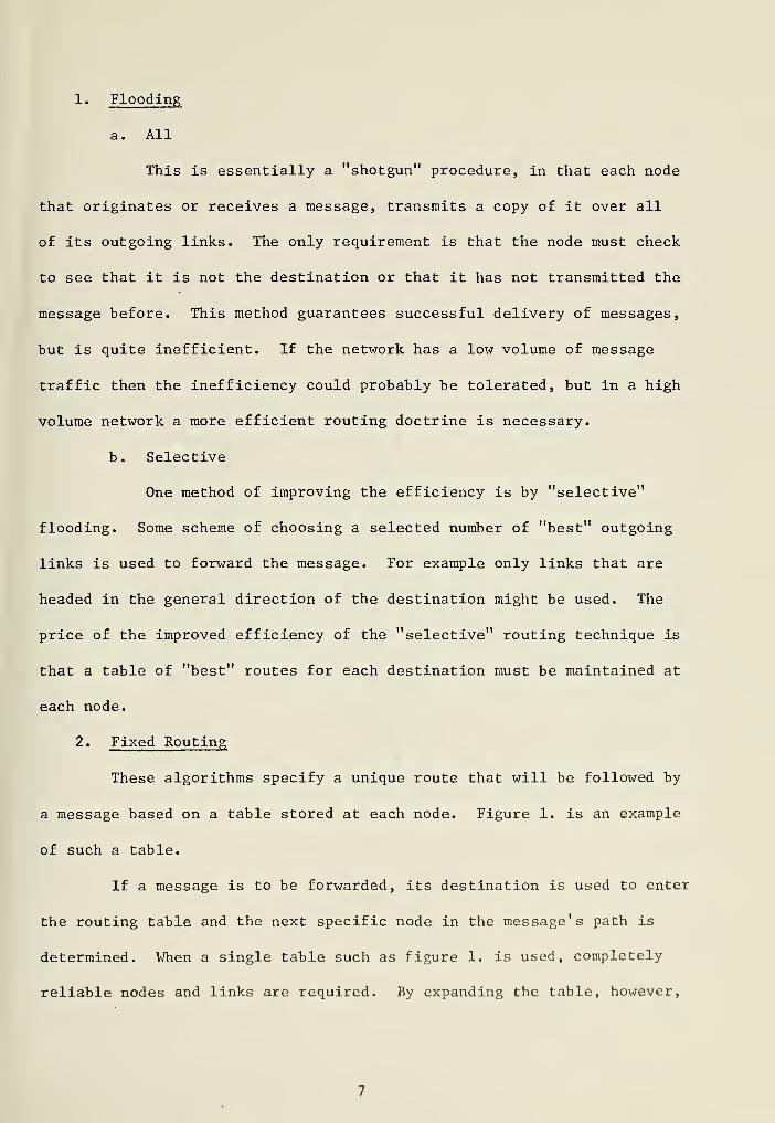
2. Fixed Routing
These algorithms specify a unique route that will be followed by
a message based on a table stored at each node. Figure 1. is an example
of such a table.
If a message is to be forwarded, its destination is used to enter
the routing table and the next specific node in the message's path is
determined. When a single table such as figure 1. is used, completely
reliable nodes and links are required. By expanding the table, however,


Next Node Number
<D
ndO£h
Pi
o•H-PCtS
•H-PWd)
P
1 3
2 1
3 4
4 6
6 9
7 9
8 9
9 10
10 8
11 8
Figure 1.
Node 5 Routing Table


alternate routes could be determined in the event of failure to the
"primary next-node". The trade off here is obvious in that large storage
areas at each node and more complex "look-up" procedures would be required.
3. Network Routing Control Center (NRCC)
With this technique, one of the nodes is designated as the NRCC.
This node collects performance information from all other nodes about the
network's performance, computes routing tables and then transmits the
appropriate routing table to all nodes in the network. Since this
computation is done on a global basis, loop-free paths are maintained
between all source-destination node pairs. A fixed routing procedure is
used between updates. The disadvantages of this technique are low re-
liability, cost of extra equipment and the fact that if the period between
updates is very long then the routing tables may be out of date with
respect to the current state of the network.
4. Ideal Observer Routing
This technique is essentially a scheduling problem. Each time
a message enters a source node for routing, its route is computed to
minimize the travel time through the network. This computation is based
upon the complete present information about the messages already in the
network and their known routes. If any future information is known about
the network or the routes, then this information could also be used in
the computation of the route. From a theoretical standpoint, this method
provides a minimum average message delay through the network and may be
used as a "standard" to which other routing techniques could be compared.
a. Ideal Routing Table & Shortest Path Problem
An underlying problem in all deterministic routing techniques
is the setting up of the routing tables. Boehm and Mobley treat this as

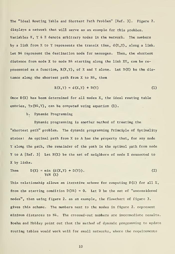
The "Ideal Routing Table and Shortest Path Problem" [Ref. 3]. Figure 2.
displays a network that will serve as an example for this problem.
Variables X, Y & Z denote arbitrary nodes in the network. The numbers
by a link from X to Y represents the transit time, d(X,Y), along a link.
Let N4 represent the destination node for messages. Then, the shortest
distance from node X to node N4 starting along the link XY, can be re-
presented as a function, R(X,Y), of X and Y alone. Let D(X) be the dis-
tance along the shortest path from X to N4, then
R(X,Y) = d(X,Y) + D(Y) (1)
Once D(X) has been determined for all nodes X, the ideal routing table
entries, Tx(N4,Y), can be computed using equation (1).
b. Dynamic Programming
Dynamic programming is another method of treating the
"shortest path" problem. The dynamic programming Principle of Optimality
states: An optimal path from X to A has the property that, for any node
Y along the path, the remainder of the path is the optimal path from node
Y to A [Ref. 3] Let N(X) be the set of neighbors of node X connected to
X by links.
Then D(X) = min (d(X,Y) + D(Y)). (2)
YeN (X)
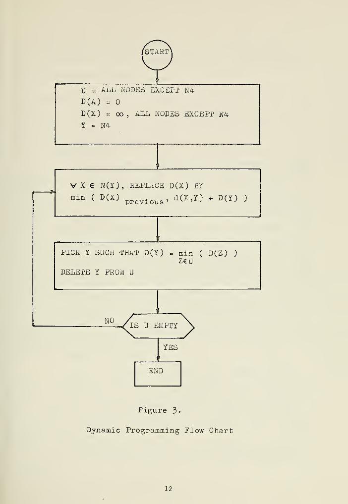
This relationship allows an iterative scheme for computing D(X) for all X,
from the starting condition D(N4) = 0. Let U be the. set of "unconsidered
nodes", then using figure 2. as an example, the flowchart of figure 3.
gives this scheme. The numbers next to the nodes in figure 2. represent
minimum distances to N4. The crossed-out numbers are intermediate results.
Boehm and Mobley point out that the method of dynamic programming to update
routing tables would work well for small networks, where the requirements
10

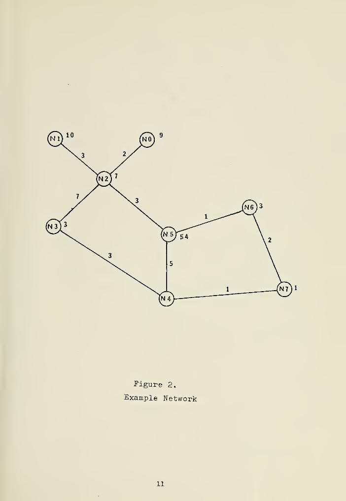
Figure 2.
Example Network
11

@U = ALL NODES EXCEPT N4
D(iL) =
D(X) = oo, aLL NODES EXCEPT N4
Y = N4
V X € N(Y), REPLACE D(X) BY
min ( D(X) . , d(X,Y) + D(Y) )v v y previous' "^^ lX ^ "\±j j
PICK Y SUCH 'THAT D(Y) = min ( D(Z) )
Z€U
DELETE Y PROM U
NO
Figure 3-
Dynamic Programming Flow Chart
12

on computer storage and speed are low [Ref. 3]. It's rather obvious
that as the number of nodes and links increases, then these requirements
become more difficult to meet.
B. STOCHASTIC TECHNIQUES
Kleinrock, Boehm, and Mobley all classify stochastic routing techniques
into three basic categories [Refs. 1, 3],
1. Random Routing
This method of routing is very similar to the "flooding" technique
discussed under deterministic methods. The main difference being that
the decision of where to route the message is based on some probability
distribution over the set of neighboring nodes. Prosser has investigated
various random routing techniques and compared their results [Refs. 4, 5].
He demonstrated that although these techniques were highly inefficient,
they were also very stable. Given enough time, a message is sure to get
through to its destination. Under normal operating conditions, the degree
of ineffeciency would probably not be tolerated, but in an extremely
hostile environment, where reliability becomes the dominating factor, a
network using random routing techniques will continue to operate in the
presence of serious network degradation,
a. Network Assumptions
An accurate analysis of a communications system operating
under a random routing procedure is very difficult to achieve. However,
by introducing some broad assumptions designed to simplify the analysis
some "rough" estimates of the operating characteristics of such a system
can be examined [Ref. 4].
For the purpose of this analysis the following assumptions
are made:
13

1) The network is a connected graph consisting of a fixed
number of nodes, n, and each node is connected to approximately k
neighbors.
2) Messages originate at each node of the network with a
Poisson distribution in time of mean X and with an exponential distri-
bution in length of 1/y . Both X and y are the same for all nodes.
3) Each message is addressed to a node in the network
chosen at random.
4) Each node has a finite queue of messages to be relayed
which operates First-in, First-out.
Using these broad assumptions some information about the network can be
computed.
b. Number of Messages in Network
Frist, the average total number, N(t), of messages in the
network at the end of a given cycle, t, can be estimated. This is
determined by:
1) The average total number of messages in the network at
the end of the last cycle i.e., N(t-l)
2) The average total number of messages added to the network
during a given cycle i.e., X n
3) The average total number of messages dropped from the
network during a given cycle by either being delivered or being dropped
due to insufficient storage. (Assume that the storage is sufficient.)
This is just the fraction, f, of N(t) handled during a cycle, times the
probability, p, that one of these messages will be delivered to its desti-
nation, divided by the expected number of cycles 1/y required to deliver
a message, i.e., upfN(t-l). Therefore
N(t) = N(t-l) + Xn - ppfN(t-l) (4)
14


By assuming that the system is empty at t = i.e. N(0) = 0, then the
behavior of N(t) as t -* °° can be investigated. The behavior depends only
on the assumptions made about f and p. The particular routing procedure
that is used will determine p, and if the messages are assumed to be
independently randomly distributed throughout the network, then Prosser
[Refs. 4, 5] demonstrates that by using the methods of Riordan, the
expected value of f is given by:
f(N)=n-fl^l < 5 >
Notice that
n/N if N»nf(N) - (6)
1 if N«n
If N»n, then equation (A) becomes the first-order difference equation:
N(t) = N(t-l) + (X - pp)n (7)
whose solution is
N(t) = (X - up)nt [Refs. A, 5] (8)
Notice that as t - °°, N(t) -> °° . This implies that if N»n then
the network has no steady-state. If N<<n, then equation (1) becomes
N(t) = N(t-l) + Xn-UpN(t-l) (9)
whose solution is
N(t) = n/upU-U-yp)11
) (10)
As t -* °° in this case then equation (10) becomes
N(t) = n/up (11)
which is a steady state solution.
15

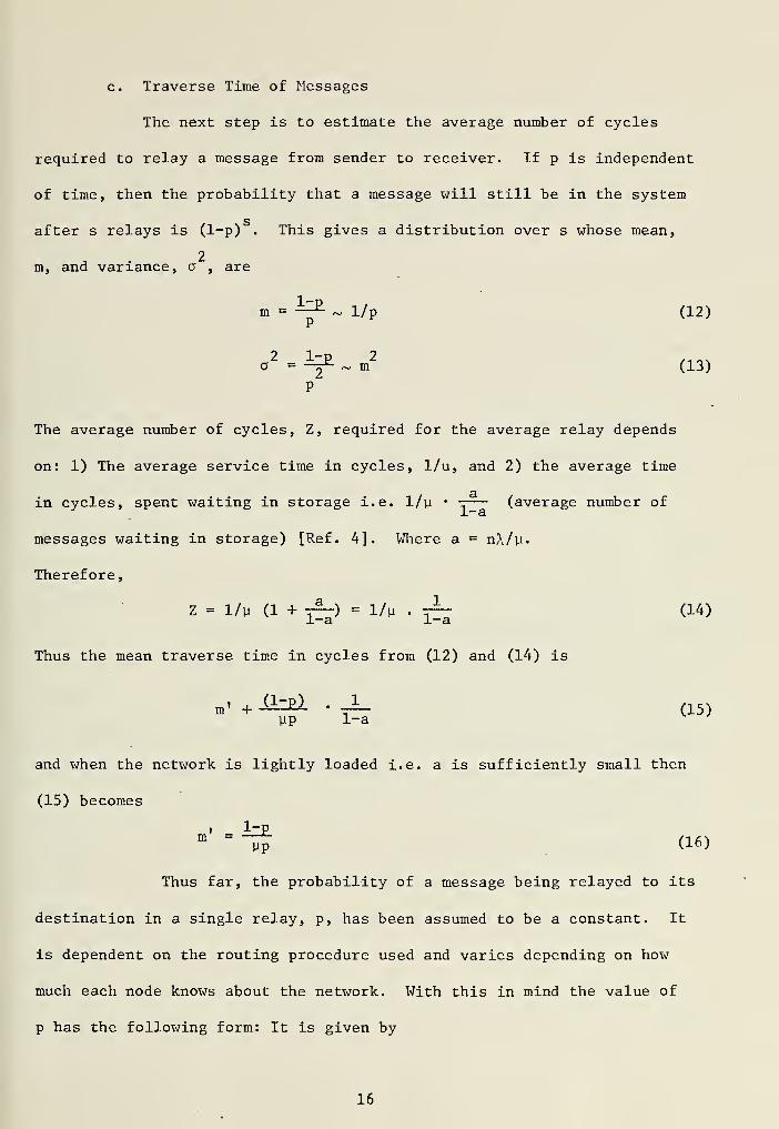
c. Traverse Time of Messages
The next step is to estimate the average number of cycles
required to relay a message from sender to receiver. If p is independent
of time, then the probability that a message will still be in the system
after s relays is (1-p) . This gives a distribution over s whose mean,
2m, and variance, a , are
m =^ ~ 1/p (12)
o2
=^ ~ m2
(13)
The average number of cycles, Z, required for the average relay depends
on: 1) The average service time in cycles, 1/u, and 2) the average time
in cycles, spent waiting in storage i.e. 1/y • rr— (average number of
messages waiting in storage) [Ref. 4]. Where a = nX/y.
Therefore,
Z = 1/y a+^rz) = l/v • -r~ (14)1-a ±-a
Thus the mean traverse time in cycles from (12) and (14) is
m . +S1Z£1 .1
(15)yp 1-a
and when the network is lightly loaded i.e. a is sufficiently small then
(15) becomes
MPm " (16)
Thus far, the probability of a message being relayed to its
destination in a single relay, p, has been assumed to be a constant. It
is dependent on the routing procedure used and varies depending on how
much each node knows about the network. With this in mind the value of
p has the following form: It is given by
16


1) The probability that the message is located at a
neighbor of its destination.
Multiplied by
2) The probability that this neighbor will relay the
message to its destination.
Various cases can now be examined.
1) Pure Random:
Each node knows only its own identity. Thus each node
relays every message to one of its k neighbors selected at random. In
this case the "destination" of the message consists of the addressee,
and there are k neighbors of this destination. The probability that the
message is located at such a neighbor is k/n. Thus
p = k/n • 1/k = 1/n (17)
2) First Order Neighbors:
Each node knows the identity of itself and the identity
of each of its neighbors. Messages are still relayed at random unless
addressed to a neighbor, in which case they are relayed to that neighbor.
The "destination" now consists of k + 1 nodes (addressee plus k neighbors)
,
The number of neighbors of this destination depend somewhat on the details
of the network graph. If the neighbors of each node are located somewhat
randomly throughout the network, then they are relatively independent
of each other and there are approximately k(k-l) neighbors of the desti-
nation. The probability that a message is located at one of these
neighbors is then
p = ifcll . 1/k = iszl (18)
17

3) Second Order Neighbors:
Each node knows the identity of itself, its neighbors,
and their neighbors. This is an extension of (a) and (b) and the proba-
bility that a message is located at a "destination" is
= k(k-l)2
. 1/k = (k-1)2
n n
This proceedure can be continued for as many "destinations"
as necessary. However it is eveident that the more information each node
has about the net, the higher the probability becomes that the message will
be delivered in a certain period of time. The results can be summarized
as follows: [Refs. 4, 5]. If the " destination" of a message is defined
as the set of nodes which know the location of the addressee node and can
assure a deterministic path to the addressee node, and if there are h
neighbors of this destiantion, each of them connected to the destination
in j different ways, then
p = h/n • j/k (20)
2. Isolated Techniques:
This class of routing algorithms operate by forming a "delay table"
at each node. The entries of the delay table, T.(D,L ), are the estimated
delays of going from the present node, (say j), to some destination node,
D, using various output lines, L . A "routing table" is then formed by
choosing the output line, OL (i) , with the minimum delay time entry for
each destination, i. Formally:
°Vi) " Tn}Ti
C1 'V <21>
18

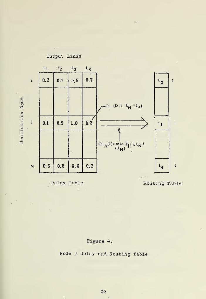
Where (L } is the set of output line numbers. Figure 4 is an example of
a delay table and a routing table for an arbitrary node J. The manner in
which these delay tables are formed, and how their entries are determined
is basically a function of the specific algorithm used. Some problems
arise using these techniques. For example", if two messages, each headed
for the same destination, arrive at an intermediate node at approximately
the same time. Both need the same outgoing link. One solution is to
store one of the messages until the best outgoing link is available,
but this could require an extremely large storage capacity at some
intermediate nodes, especially if they are on the main artery of traffic
flow. An alternate solution to this problem is to include in the "routing
table" at each node not only the best outgoing link, but the next best
link etc. An incoming message is then routed out on the best link
available at the time. Two algorithms using isolated techniques are
discussed here.
a. Shortest Queue Plus Zero Bias
This algorithm is also referred to by Baran as "Hot-Potato
Routing" [Ref. 6], With this algorithm, a message's route is selected by
placing it in the shortest output queue. Since the route is chosen
independent of the messages destination, the delay table, figure 4, is
reduced to a single row, where the row entries would reflect the output
queue lengths. It is now obvious that much bookkeeping is necessary at
all the nodes. Methods must be devised to keep the routing table current
and the "best" queue lengths for each outgoing link must be determined.
Further, some method for "dropping" messages from the network (when all
queues are full) must be considered.
b. Local Delay Estimate or Backward Learning
This method uses the delay table and the routing table of
19

Output Lines
l\ L2 L;
o
doH-Po5
fl
•H+5CO
CD
P»
N
0.2 0.1 0.5 0.7
>
0.1 0.9 1.0y
0.2
0.5 0.8 0.6 0.2
T: (D = l. LN =l 4)
-X
?
OLN(i)rmi nTj (i,LN )
'L N) <
N
Delay Table Routing Table
Figure 4.
Node J Delay and Routing Table
20

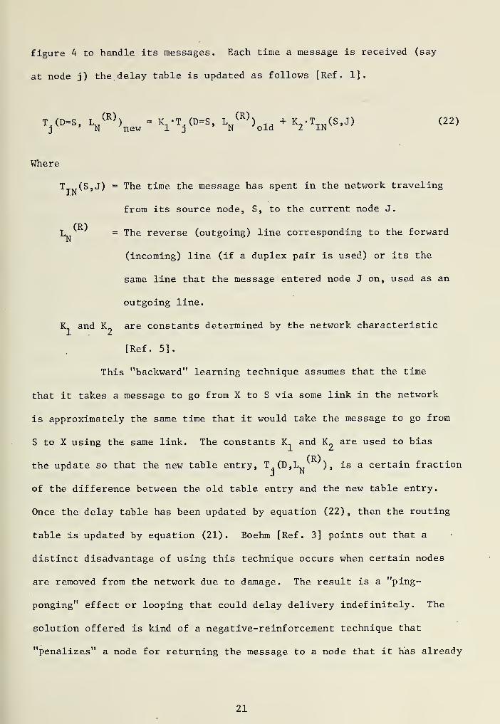
figure 4 to handle its messages. Each time a message is received (say
at node j) the delay table is updated as follows [Ref. 1]
.
T, (D=S, L(R)
) = K -T.(D=S, L„(R)
) ,, + K -T (S,J) (22)j N new 1 2 N old 2 IN
Where
T (S,J) = The time the message has spent in the network traveling
from its source node, S, to the current node J.
(R)L = The reverse (outgoing) line corresponding to the forwardN
(incoming) line (if a duplex pair is used) or its the
same line that the message entered node J on, used as an
outgoing line.
VL and K are constants determined by the network characteristic
[Ref. 5].
This "backward" learning technique assumes that the time
that it takes a message to go from X to S via some link in the network
is approximately the same time that it would take the message to go from
S to X using the same link. The constants K and K„ are used to bias
(R)the update so that the new table entry, T.(D,L ) , is a certain fraction
of the difference between the old table entry and the new table entry.
Once the delay table has been updated by equation (22) , then the routing
table is updated by equation (21). Boehm [Ref. 3] points out that a
distinct disadvantage of using this technique occurs when certain nodes
are removed from the network due to damage. The result is a "ping-
ponging" effect or looping that could delay delivery indefinitely. The
solution offered is kind of a negative-reinforcement technique that
"penalizes" a node for returning the message to a node that it has already
21

been to. The "penalty" is in the form of a constant added to the delay
table entry, which will then cause all messages bound for a certain
destination to try a different route. Again, another disadvantage occurs
in the form of the delay tables having very large entries. This will
happen since "looping" for short periods of time cannot be avoided using
stochastic routing techniques. Eventually entries in the delay table
would have to be re-initialized. A good synthesis of the backward
learning technique and the negative reinforcement is what Boehm calls
the bi-adaptive technique. It uses the backward learning technique
to decrease the delay table entries to correct overcompensations of
negative reinforcements. This is satisfactorily accomplished by setting
K_, in equation (22), to zero for the particular calculation. It is now
necessary for the node to recognize messages that have been there before,
but this could be accomplished by setting a flag bit on the message itself.
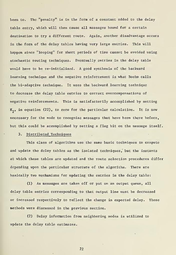
3. Distributed Techniques
This class of algorithms use the same basic techniques to compute
and update the delay tables as the isolated techniques ,' but the instants
at which these tables are updated and the route selection procedures differ
depending upon the particular structure of the algorithm. There are
basically two mechanisms for updating the entries in the delay table:
(1) As messages are taken off or put on an output queue, all
delay table entries corresponding to that output line must be decreased
or increased respectively to reflect the change in expected delay. These
methods were discussed in the previous section.
(2) Delay information from neighboring nodes is utilized to
update the delay table estimates.
22


It is method (2) that will be discussed here. Referring to figure 5.,
suppose, by some method, a decision has been made at node J to inform its
neighbors (N , N , N ) of its current estimated delays to reach all nodes
in the network. Node J forms a "minimum delay" vector say V = (T(l),•J
f-Vi
T(2), ), where the k entry in the vector, T(K) = min T. (K,L ),
and transmits V to its neighbors (Nl, N2 , N3) . Upon receipt of the
minimum delay vector, a node (say Nl) adds its current output line queue
length (line L for this example) plus a constant, Dp, to all entries
in the vector V and replaces column 1 (corresponding to line Ln) in the
delay table with these new values. The updated table entries for node
M are:
TM(D'V = Q(M'V + Dp + T(D) (23)
Where
Q(M,L ) is the queue length at line number N at node M.
The constant Dp is used to control the degree of alternate routing and the
sensitivity of the algorithm to small variations in queue length. That
is, if Dp is large compared to the average queueing delay in a node,
then the path chosen for a message would tend to be one of the paths
that would encounter the smallest number of lines enroute to its destina-
tion [Ref. 1]. There are basically two methods which can be used to cause
the delay vector, V , to be transmitted.J
a. Periodic Update
The periodic updating algorithm forces these transmissions
at fixed periods of time.
b. Asynchronous Update
This algorithm can cause an update to be transmitted, after
23


TO)
T(k)ir
T(N)
T(k) - min TjOcL^)
L2L3
Vector V T
Figure 5«
Minimum Delay Vector and Example Network Segment
24

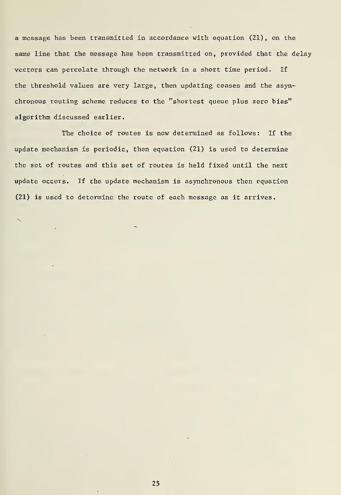
a message has been transmitted in accordance with equation (21) , on the
same line that the message has been transmitted on, provided that the delay
vectors can percolate through the network in a short time period. If
the threshold values are very large, then updating ceases and the asyn-
chronous routing scheme reduces to the "shortest queue plus zero bias"
algorithm discussed earlier.
The choice of routes is now determined as follows: If the
update mechanism is periodic, then equation (21) is used to determine
the set of routes and this set of routes is held fixed until the next
update occurs. If the update mechanism is asynchronous then equation
(21) is used to determine the route of each message as it arrives.
25

III. USE OF MICRO-COMPUTERS IN THE COMMUNICATIONS NETWORK
In the preceeding sections, no restriction was placed on the size
of the computer that would handle the message routing at each of the
nodes. These computers could have been Micro, Mini, or large-scale.
Further, no consideration was given to the amount of memory necessary
at each node to be able to handle the more sophisticated algorithms.
In this section, I would like to examine the feasibility of using micro-
computers at each of the nodes and discuss which, if any, of the algorithms
are still usable with this new restriction on the network. The micro-
computer that will be considered as a candidate for use in the network
will be INTEL Corporation's MCS-8 [Ref. 11]. Before discussing the
characteristics of the MCS-8, some possible network applications should
be mentioned.
A. MILITARY APPLICATIONS
Generally speaking, communication networks that are in use today are
very large scale, such as the ARPA network which is used to pass data
between computers across the United States, and the Bell Telephone System
that routes communication traffic throughout the United States and Overseas.
In this paper, the networks under consideration will be restricted to
a somewhat smaller scale, and will be used for military purposes. For
example, a possible network might be set-up aboard a large ship or at a
shore station to monitor and route all incoming communication traffic,
whether it be Broadcast or Tactical. A network of this sort would require
one or more micro-computers at each station to screen the messages that
are received from other stations and either forward them to their
destination or to drive a teletype if the message is for their station.
26


A more abmitious application might be the replacement of the present
NTDS system by an NTDS network aboard our large combatants. For this
application, the computing that is presently being done by large "cen-
tralized" computers could be distributed throughout the ship. For example,
radar information received in CIC concerning a target, must currently be
sent to the NTDS computer for processing where the target's course, speed,
and CPA are computed and then that information is passed to a weapon
system of some sort to engage the target. In the proposed network, micro-
computers in CIC would receive target data from the radars and compute the
target's course, speed and CPA. A second micro-computer that could
communicate with each of the "radar" micro-computers would have the task
of designating targets according to some priority scheme. Another micro-
computer, somewhere else, might have the task of selecting a weapon, and
another micro-computer at the weapon station might have the task of training
the guns or aiming the missiles. By distributing the tasks normally done
by a "centralized" computer, a remarkable increase in the reliability of
the entire system can be realized. For example, loss of any part of the
network would not cause the network to fail, whereas failure to the
"centralized" computer does cause the system to fail. What is needed to
make the network operational is a means of communication for the micro
computers: Some method of routing messages from station to station. It
is worthwhile to mention here, with the cost of micro-computers being what
they are today, that a network of approximately one-thousand micro-computers
could be implemented for the same hardware cost as our present NTDS system.
B. THE MCS-8 MICROCOMPUTER SET
The MCS-8 microcomputer set is made up of a model 8008 single-chip
MOS 8-bit parallel processor interfaced with any type or speed standard
27


semi-conductor memory of up to 16k 8-bit words [Ref. 11]. The processor
communicates over an 8-bit data and address bus and uses two input leads
(READY and INTERRUPT) and four output leads for control. Time multiplexing
of the data bus allows control information, 14-bit addresses, and data to
be transmitted between the CPU and external memory. The CPU contains six
8-bit data registers, an 8-bit accumulator, two 8-bit temporary registers,
four flag bits, and an 8-bit parallel, binary, arithmetic unit which im-
plements addition, subtraction, and logical operations. A memory stack
containing a 14-bit program counter and seven 14-bit words is used in-
ternally to store program and subrouting addresses. The 14-bit address
permits the direct accessing of 16k words of memory which may be any mix
of RAMs, ROMs, or shift-registers. The control portion of the CPU contains
logic to implement a variety of register transfer, arithmetic control,
and logical instructions. Most instructions are coded in one byte (8-bits)
;
data intermediate instructions use two bytes, and jump instructions use
three bytes. Presently operating with a 500 KHz clock, the CPU executes
non-memory referencing instructions in 20 microseconds. The instruction
set for the 8008 consists of 48 instructions including data manipulation,
binary arithmetic, and jump-to-subroutine. The normal program flow of the
8008 may be interupted through the use of the INTERRUPT control line.
This allows servicing of slow I/O peripherals while also executing the main
program. The READY command line synchronizes the CPU to the memory cycle
allowing any type or speed of semiconductor memory to be used. Figure 6
is a block diagram of the 8008 central Processing Unit [Ref. 11].
The four basic functional blocks of the CPU (figure 6.) are the instruc-
tion register, memory, arithmetic logic unit (ALU), and I/O buffers. They
communicate with each other over the internal data bus.
28


-~s^--™-^7?j-
<Z
«*
QnniH3aoo3a sssuaavQVd H01VHDS
i hj>;
a3X3TdinnwSSSWaCWaVd HDlVilDS
ADDRESSPOINTER
AHL
,5-®—«>
**»
i. ll
oz< cc
o z<H* < 13
1- OVI u
>
a-* Qo
ooCD
a.
rrT^xinrra3ao33a
SS3bQQV X3V1S
il ll
a3X3Tdinrn'jSS3aOQV MDViS
5 2
>- o
o cc
* o
I o !
a >-
s. '
occ
•-
5 wK O 2 t« 2 5 z5 < '
UJ 55 S
5 o
„.,
.Q •
cc
to
o COUJcc
ii "mi
—®£
Si-^-®
E<0fc.
CIra
-Sk Q-*-& ^
CJ o•a
CO
-»Hg> nooOz
oCO
-0
3
29


The instruction register is the heart of all processor control.
Instructions are fetched from memory, stored in the instruction register,
and decoded for control of both the memories and the arithmetic logic
unit.
Two separate dynamic memories are used in the 8008; the push down
address stack and a scratch pad. The address stack contains eight 14-bit
registers, providing storage for eight lower and six higher order address
bits in each register. One of these registers is used as the program
counter and the other seven permit address storage for the nesting of
subroutines. The stack automatically stores the content of the program
counter upon execution of a CALL instruction and restores the program
counter upon execution of a RETURN. A three-bit address pointer is used
to designate the present location of the program counter. When the
capacity of the stack is exceeded the address pointer recycles and the
content of the lowest level register is destroyed. The 14-bit program
counter provides direct addressing of 16k bytes of memory. Through the
use of an I/O instruction for bank-switching, memory may be indefinitely
expanded. The scratch pad contains the accumulator and six other 8-bit
registers. These registers are independent and may be used for temporary
storage. Two of these registers may be used for indirect addressing.
All arithmetic and logical operations are carried out in the 8-bit
parallel arithmetic unit which includes carry-look-ahead logic. Two
temporary registers are used to store the accumulator and the operand for
all ALU operations, or they may be used for temporary address and data
storage during intra-processor transfers. Four control bits are set as
a result of each arithmetic and logical operation. These bits provide
conditional branching capability through CALL, JUMP, or RETURN-ON-CONDITION
instructions and also the ability to do multiple precision binary arithmetic
30

The I/O buffer is the only link between the processor and the rest of
the system. Each of the eight buffers is bi-directional and is under
control of the instruction register and state timing. Each buffer is low
power transistor-to-transistor logic (TTL) compatible on the output and
the input
.
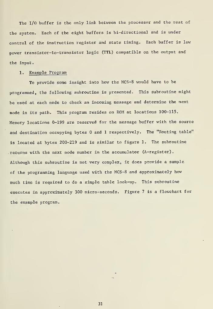
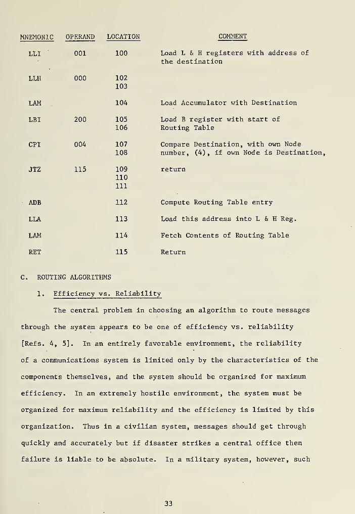
1. Example Program
To provide some insight into how the MCS-8 would have to be
programmed, the following subroutine is presented. This subroutine might
be used at each node to check an incoming message and determine the next
node in its path. This program resides on ROM at locations 100-115.
Memory locations 0-199 are reserved for the message buffer with the source
and destination occupying bytes and 1 respectively. The "Routing table"
is located at bytes 200-219 and is similar to figure 1. The subroutine
returns with the next node number in the accumulator (A-register)
.
Although this subroutine is not very complex, it does provide a sample
of the programming language used with the MCS-8 and approximately how
much time is required to do a simple table look-up. This subroutine
executes in approximately 300 micro-seconds. Figure 7 is a flowchart for
the example program.
31


100-106
LOAD LOCATION OF DESTINAiTOAi
LOAD A.-REG. WITH DESTINATIONLOAD B-REG. WITH 200
107-111
^COMPARE WITH OWN -.OUi,, ,.,!:;•.'.;,,
112-113. ^
COMPUTE ROUTING TABLE ENTRI
114
FETCH l
'!}iEXi: i^ODE" FROM TaBLE
115
Figure 7-
Subroutine to Determine Next Node
32

MNEMONIC OPERAND LOCATION COMMENT
LLI
LLH
LAM
LB I
CPI
JTZ
ADB
LLA
LAM
RET
001
000
200
004
115
100
102
103
104
105106
107108
109110
111
112
113
114
115
Load L & H registers with address of
the destination
Load Accumulator with Destination
Load B register with start of
Routing Table
Compare Destination, with own Nodenumber, (4), if own Node is Destination,
return
Compute Routing Table entry
Load this address into L & H Reg.
Fetch Contents of Routing Table
Return
C. ROUTING ALGORITHMS
1. Efficiency vs. Reliability
The central problem in choosing an algorithm to route messages
through the system appears to be one of efficiency vs. reliability
[Refs. 4, 5]. In an entirely favorable environment, the reliability
of a communications system is limited only by the characteristics of the
components themselves, and the system should be organized for maximum
efficiency. In an extremely hostile environment, the system must be
organized for maximum reliability and the efficiency is limited by this
organization. Thus in a civilian system, messages should get through
quickly and accurately but if disaster strikes a central office then
failure is liable to be absolute. In a military system, however, such
33

a loss cannot be tolerated. Degradation must be gradual and messages
must get through even after a loss of a large part of the system.
Any large-scale civilian communications system should probably be
essentially a directory system: Every operating station in the system
should either have a directory of its own or have access to one which
contains complete information on how to reach every other station in
the network. In many cases there could also be a "central" station
whose task it is to handle, or assist in handling, the routing of messages
through the network. This type of organization has the advantage that
very efficient routing procedures can be obtained by all stations from
the directory, but it has the obvious disadvantage that it depends heavily
upon this directory. This system will work fine when failures in the
system are few, but in a hostile environment the disadvantages are likely
to outweigh the advantages because any change in the system requires a
revision of the directory of every station in the network.
In contrast to the above, any military communications system operating
in a hostile environment should probably operate as a random system. There
are no directories to maintain and each station will send messages to
whatever station it can, based on whatever information it has, and hopes
for the best. This type of operation is likely to be extremely inefficient,
but has the advantage that it will continue to operate in the presence of
serious degradation. In a favorable environment the disadvantages surely
outweigh the advantages of such an organization and such a degree of in-
efficiency would not be tolerable unless conditions were indeed desperate.
This problem can be restated in terms of the information available to
each station about the rest of the network. The directory system supposes
that each station has complete and accurate information about every other
34


station in the network and routes messages based on this information.
Such a system can be made efficient but has the problem of devising
optimum routing procedures from this information and keeping this in-
formation up to date. On the other hand, stochastic techniques suppose
that no station has complete information about the system and routes
messages based on random choices or by some other method depending on
what information is available to each station. Such a system can be
made reliable, but it must be determined how to make this system efficient.
It is likely that a military system operating under a variety of conditions
will necessarily incorporate elements of both the directory and stochastic
techniques, the proportion being determined by the particular use of the
network and the computing machinery "available.
2 . Deterministic Techniques
A communications network using micro-computers at each node should
be able to operate quite effectively using deterministic techniques as
routing algorithms. The "flooding" or "selective flooding" algorithms are
compatible with the MCS-8 microcomputer with only a slight increase in
message transit time realized. This is due to the relatively slow (20
microsecond) instruction cycle of the MCS-8 as compared to the faster
times of most large-scale or even minicomputers. For certain applications,
where low-volume message traffic is the rule, a very reliable network
could be had. The inherent inefficiency of this type of algorithm could
be reduced somewhat by including a table of "best" routes, hence selec-
tive flooding, but the small increase in the efficiency of the network
would have to be weighed against the further increase in message transit
time.
35

On the opposite end of the scale of highly reliable flooding
techniques are the very efficient "Network routing Control Center, (NRCC)"
and the "Ideal Observer" methods of handling messages within this network.
The MCS-8 is quite capable of functioning as an NRCC providing that the
time requirement for updating routing tables is not too critical, and the
network is small enough to allow the MCS-8 to monitor and control all nodes.
If this method were to be used for large networks, then a small group of
MCS-8 's could be used, each monitoring their own segment of the network
and communicating with each other concerning the status of net. The
unacceptable level of reliability of this configuration tends to override
the high efficiency and makes this method impractical for military appli-
cations. As stated earlier, the "Ideal Observer" method has doubtful
application in any type of network with any type computer, and should be
used only as a theoretical aid.
The use of "Fixed Routing" techniques seems to be a suitable
compromise of the other methods that can easily be handled by the MCS-8
network. This method, with its fixed routing table at each node, would
require a table look-up each time a message arrived at a node. This table
look-up would cause some increase in the message transit time, but even
with the slow processing time of the MCS-8, this increase would be toler-
able. The problem of increasing the reliability, predominant in nets
using deterministic techniques, seems to be more easily overcome using
fixed routing tables than in the nets using a NRCC; this method allows
a higher volume of traffic than could be allowed using flooding techniques.
To accomplish this compromise, a modification of the routing table in
figure 1. is necessary. The new routing table, figure 8., although fixed,
now offers alternate routes should the primary "next node" be "down" for
36


>®
^u «>?o^
4F
£&5
*? <5?
^
&
Pi
(D
o125
PIO•H+3ctf
Pi
•H-PW(D
10
11
3 2 • • •
• » •
7
1 7 4
4 6 9
6 10 1 1
9 1 1 4
9 1 1 4
10 6 5
8 7 5
8 4 9
7 4 6
Figure 8.
Modified Routing Table
37


any reason. The number of alternate routes included in the table increases
with the amount of reliability required and would vary depending on the
application of the network. The possibility exists that these tables
might become quite large in a large network, but with the low cost of the
MCS-8, several of these micro-computers could be placed at each node to
accomodate the large tables and still do the necessary tasks assigned to
the node. Some problems that would have to be solved when using this
method are:
1) How to determine when the primary "next node" is down.
2) Once it has been determined that the primary node is down,
how should the routing table be modified, and
3) How can a previously down node, that is now operational,
be recognized as operational.
3. Stochastic Techniques
In contrast to the deterministic techniques, the stochastic
algorithms are not as easily adapted to an MCS-8 micro-computer network.
In general, attempts to increase the efficiency of a network using these
techniques result in very long delay times at each node and tend to raise
the overall transit time to an unacceptable level. The possible exception
being the "Random" routing technique which is very similar to the "Flooding"
technique discussed previously. In a low volume network, where efficiency
is of minor concern, either of these methods could be used very effectively.
All other stochastic techniques use a delay table and attempt to bring
the efficiency of the network up to an acceptable level by keeping this
delay table as current as possible. The requirement is that longer
messages or additional messages must be introduced into the network; and,
for some algorithms, a queue must be set-up at each node ("Hot-Potato"
38


routing). In all cases, though, comples algorithms must be used at
each node to keep the delay tables current.
IV. CONCLUSIONS
The MCS-8 is capable of meeting the requirements for large storage
areas and/or complex algorithms by having a group of computers at each
node and assigning each a specific portion of the tasks to be accomplished.
The problem however, is that messages may be delayed for an abnormal
length of time while the table is being updated and some loss in node
reliability would be realized, since a loss of any one of the computers
at the node would cause the node to fail.
A. ALGORITHM SELECTION
The most adaptive of the stochastic techniques is the "Backwards
Learning" technique. Although this method does require a more complex
algorithm to reduce the "ping-ponging" effect in the network, it does not
introduce new messages into the network, as is the case with the "Delay
Vector" techniques, and the tables required at each node are similar in
size to the routing tables described under Deterministic Techniques. This
technique does require that the estimated delay time be added to a
message at each node and the delay table be updated each time a message
is received or transmitted.
In summarizing the above observations, it is apparent that there is
no single "best" algorithm that can be utilized in the MCS-8 micro-computer
network, but the choice of algorithm depends on the requirements imposed
on a particular application. It does appear, though, that the "modified"
fixed routing table, figure 8., offers a degree of efficiency and re-
liability that is acceptable for most applications. If a stochastic
39

algorithm must be used, as would be the case when "best" routes were con-
tinually changing, then the "Backward Learning" technique seems most com-
patible with the MCS-8 network. Although this method requires a more
complex algorithm, it does offer good efficiency and reliability and
should not be too difficult to implement.
B. FUTURE STUDIES
During the research and writing of this paper, some additional problems
were uncovered concerning micro-computer networks. These problems are
presented here for possible future study.
1. Topology Studies
For a given application, determine the configuration of the network
required to provide the optimum message delivery rate. This study would
probably require simulating various network configurations. For networks
that are very small, it is possible that the best method may be to connect
each computer in the network to every other computer, hence eliminating
the need for routing algorithms altogether. As the network grows, however,
a point is reached when routing algorithms become necessary for efficient
operation.
2. Programming Algorithms
The routing algorithms proposed as acceptable should be written
and studied to determine what the actual delay time would be at each node.
3. Message Construction
The length of the message is important because it determines the
buffer size necessary at each node. The physical construction may vary
depending on the specific network application but the optimum size should
be determined. The construction will also be affected if the message must
be transmitted in parts.
40

4. Message Handling
The problem of what to do when two or more messages arrive at a
node at approximately the same time must be considered. Multiple buffers
for nodes that are on a high traffic path may be necessary, but too many
buffers would increase the delay time at each node. A priority scheme
should probably be introduced in a multiple-buffered node to ensure that
priority traffic is handled first. The method of handling multiple
destination messages should also be considered.
5. Applications
Microcomputer network applications other than those mentioned
herein, should be studied.
6. Node Improvements
The affect of faster, larger storage micro-computers on network
performance should be studied. For example, INTEL Corporation has plans
of manufacturing a 2 microsecond, processor, the 8080, that is capable
of handling 65K of memory. This machine may allow the use of more complex
algorithms than are presently feasible with the MCS-8 system.
41

BIBLIOGRAPHY
1. Fultz, G. L. and Kleinrock, L., "Adaptive Routing Techniques forStore-and-Forward Computer-Communication Networks," ARPA Semi-AnnualTechincal Report . Appendix D, p. 83-91, 30 June 1971.
2. Heart, F. E. Kahn, R. E., Ornstein, S. M. , Crowther, W. R. , andWalden, D. C. , "The Interface Message Processor for the ARPA ComputerNetwork," AFIPS Conference Proceedings , Spring Joint ComputerConference, May 1970.
3. Boehm, B. W. , and Mobley, R. L. , "Adaptive Routing Techniques forDistributed Communications," The Rand Corporation , Memorandum,RM-4781-PR, February 1966.
4. Prosser, R. J., "Routing Procedures in Communication Networks,Part I : Random Procedures," IRE Transactions on Communication Systems ,
CS-10, p. 322-329, 1962."
5. Prosser, R. J., "Routing Procedures in Communication Networks, Part II:
Director Procedures," IRE Transactions on Communication Systems ,
CS-10 p. 329-335, 1962.
6. Baran, P., "On Distributed Communications, I: Introduction to
Distributed Communications Networks," The Rand Corporation,
Memorandum, RM-3420-PR, Aughst 1964.
7. Frank, H. , Frisch, I. T. , and Chow, W. , "Topological Considerationsin the Design of the ARPA Computer Network," AFIPS ConferenceProceedings , Spring Joint Computer Conference, May 1970.
8. Carr, S. C. , "Host-Host Communication Protocol in the ARPA Network,"AFIPS Conference Proceedings , Spring Joint Computer Conference,May 1970.
9. Dorff, E. K. , "A Multiple Minicomputer Message Switching System,"Computer Design, p. 67-73, April 1972.
10. Baran, P., "On Distributed Communications," The Rand Corporation ,
Series of 11 Memoranda, August 1964.
11. INTEL Corporation, "8008 8-Bit Parallel Central Processor Unit,"MCS-8 Micro-Computer Set , June 1972.
42

INITIAL DISTRIBUTION LIST
No. Copies
1. Defense Documentation Center 2
Cameron StationAlexandria, Virginia 22314
2. Library, Code 0212 2
Naval Postgraduate SchoolMonterey, California 93940
3. ENS R. H. Brubaker, Jr., (Code 53Bh) 1
Department of MathematicsNaval Postgraduate SchoolMonterey, California 93940
4. Professor Gary A. Kildall, (Code 53Kd) 1
Department of MathematicsNaval Postgraduate SchoolMonterey, California 93940
5. LT James F. Howick, USN 1
590-D Michelson RoadMonterey, California 93940
43


UnclassifiedSecurity Classification
DOCUMENT CONTROL DATA -R&D{Security clas silication ot title, body of abstract and Indexing annotation must be entered when the overall report Is classified)
riginating activity (Corporate author)
ival Postgraduate School
mterey, California 93940
2«. REPORT SECURITY CLASSIFICATION
Unclassified2b. CROUP
EPORT TITLE
Study of Message Routing within a Micro-Computer Network
ESCRIPTIVE NOTES (Type ot report and.inclusive dates)
aster's Thesis; December 1972uthorisi (First name, middle initial, taat name)
ames F. Howick
EPORT DATE
acember 19727«. TOTAL NO. OF PACES
45
7b. NO. OF REFS
CONTRACT OR GRANT NO.
'ROJECT NO.
Be. ORIGINATOR'S REPORT NUMBER(S)
Bb. OTHER REPORT NOI5I (Any other number* that may be aetlgnedthis report)
DISTRIBUTION STATEMENT
pproved for public release; distribution unlimited,
SUPPLEMENTARY NOTES 12. SPONSORING MILITARY ACTIVITY
Naval Postgraduate SchoolMonterey, California 93940
ABSTRACT
The use of microcomputers in a message-switching network is introduced throughdiscussion of store-and-forward routing techniques. Algorithms that utilize3th deterministic and stochastic principles are explained and those parameterslich determine the computing machinery necessary are identified. INTEL Corporations3C-8 micro-computing system is presented as a possible candidate for use in2ssage-switching networks and some applications of these networks are discussed,modification of a routing algorithm is offered, which makes the microcomputerseable in message-switching networks.
D,F
,T..1473 <PAGE n
IOV II
0101-807-681 1 44UnclassifiedSecurity Cla»»ificetion
1-31408


UnclassifiedSecurity Classification
KEY WO BD1
Stochastic
Deterministic
Network
Microcomputer
Algorithm
)D ,
F,r..1473 ^ACK)
fN 0101-807-6821
ROLE W T
45Unclassified
Security Classification »- 31 409


Thesis 1^1321H8254 Howickc.l A study of message
routing within a micro-computer network.
I ! S E P 7 37 MAR 7429 MAY 74% AUG7S*.
tt Mftf 0«
2 1 3 3,5P 133522026236 18,
lh io
Thesis
H8254 Howick
c.l A study of message
routing within a micro
computer network.
HT321