a study of the duality between planar kinematics and staticsshai/pdfs/equimomental.pdf · a study...
TRANSCRIPT

Accepted with revisions for publication at ASME Journal of Mechanical Design
A Study of the Duality between Planar Kinematics and Statics
Offer Shai, Department of Mechanics, Materials and Systems
Tel Aviv University, Ramat Aviv 69978, Israel
Gordon R. Pennock, School of Mechanical Engineering Purdue University, West Lafayette, Indiana 47907, USA
June 12th, 2005
ABSTRACT
This paper provides geometric insight into the correlation between basic concepts underlying the kinematics of planar mechanisms and the statics of simple trusses. The implication of this correlation, referred to here as duality, is that the science of kinematics can be utilized in a systematic manner to yield insight into statics. The paper begins by introducing a unique line, referred to as the equimomental line that exists for two arbitrary co-planar forces. This line, where the moments caused by the two forces at each point on the line are equal, is believed to be an original and important concept in statics. The dual concept in kinematics is the instantaneous center of zero velocity and two theorems are presented based on the duality between equimomental lines and instantaneous centers. The first theorem states that the three equimomental lines defined by three co-planar forces must intersect at a unique point. The second theorem states that the equimomental line for two co-planar forces, acting in a truss with two degrees of indeterminacy, must pass through a unique point. The paper presents the transformation of the Kennedy circle in kinematics to the dual Kennedy circle for statics. This is believed to be an original contribution to the literature and provides a general perspective of the importance of the duality between the kinematics of mechanisms and the statics of trusses. Finally, the paper presents several examples to demonstrate how this duality provides geometric insight into planar linkages and trusses. For example, the concepts are used to identify special configurations where a linkage loses mobility and where the dual truss is not stable. Keywords: kinematics, statics, instant centers, equimomental lines, Aronhold-Kennedy theorem, dual Kennedy circle, indeterminate mechanism, dead center position, unstable truss, synthesis.

2
1. Introduction
Engineering science provides a number of duality principles [1] as illustrated by the following examples. The first example is the duality in projective geometry between lines in three-dimensional Euclidean geometry and points in two-dimensional space; i.e., a line in space corresponds to a point in a single plane [2]. This duality is used in screw theory to map homogeneous coordinates to screw coordinates [3, 4] and was employed by Pennock and Yang [5] to obtain closed-form kinematic equations for serial robot manipulators and by Tarnai [6] to prove the duality between plane trusses and grillages. Davies [7] used the principle of duality in a study of mechanical networks relating to wrenches on circuit screws. Another example is the duality between serial robot manipulators and parallel manipulators [8, 9]. The equations underlying the kinematics and the statics of these two types of manipulators are the same which makes them dual to each other. An in-depth study of first-order instantaneous kinematics and statics contributed to a better understanding of both serial and parallel robot manipulators [10, 11]. It is well-known that instantaneous kinematics and statics proceed alongside one another, the important principle of reciprocity linking the two together [12].
The duality between first-order kinematics and statics has proved to be an important concept in engineering practice [13]. The correlation is based on the principle of virtual work which implies an orthogonality between the kinematic and static variables underlying the behavior of a mechanism and a truss. In general, the mathematical basis is linear algebra and the relations can be traced through similarities in the corresponding matrices. Shai [14] presented relationships between planar linkages and determinate trusses based on the graph theory duality principle. He described the duality between linkages and trusses in some detail and showed that the statics of a truss can be represented by the kinematics of a planar linkage. The focus of this current work is the correlation between basic concepts underlying kinematics and statics and not between specific linkages and trusses. The goal is to provide the reader with a more general perspective on the duality between the sciences of kinematics and statics.
The paper begins with a definition of a new entity in statics. For two arbitrary co-planar forces there is a unique straight line in this plane where the two forces apply the same moment; i.e., the moments caused by the two forces at each point on this line are equal. This line is referred to throughout this paper as the equimomental line. The paper then introduces a relation between planar kinematics and statics that is based on the dual relation between the instantaneous centers of zero velocity (henceforth referred to as instant centers) and the equimomental line. This correlation provides a new approach to transforming knowledge between the domains of kinematics and statics. The theorems related to instant centers in single-degree-of-freedom and two-degree-of-freedom linkages will be extended to theorems in statics. Moreover, by employing the duality relation between a linkage and a simple truss, special properties of a linkage will be related to the properties of the equimomental lines of the dual truss. This is demonstrated by transforming a property of instant centers for an indeterminate mechanism and a two-degree-of-freedom mechanism, developed by Foster and Pennock [15, 16], to a counterpart property in statics. Then the result is used to identify singular configurations of a linkage and unstable configurations of the dual truss.
The remainder of this paper is arranged as follows. Section 2 presents a new theorem in statics regarding the existence of the equimomental line. Then Section 3 develops the correspondence between kinematic principles and static principles. The foundation of this correlation is shown to be the duality between instant centers and equimomental lines. On the basis of this relation, well-known kinematic theorems will be transformed to theorems in the statics of trusses. The section includes two kinematic techniques which utilize the Aronhold-Kennedy theorem and a relationship between instant centers in a two-degree-of-freedom

3
mechanism. Section 4 explains the duality relation between planar linkages and determinate trusses and presents the concept of a face force [14]. It is the face force which allows equimomental lines to be used in the static analysis of a truss. Section 5 investigates special configurations of a truss and singular configurations of a linkage. To illustrate the correspondence between the kinematic and static theorems, two examples are included; namely, a determinate truss and a double flier eight-bar linkage. For a special configuration of the truss, the truss is not stable (or not rigid) which indicates that the dual linkage will be in a locked configuration. The double flier eight-bar linkage illustrates the correlation between instant centers and equimomental lines when the linkage is in a singular configuration. Section 6 begins with a general discussion of the transformation between kinematic and statics. The section includes a new graphical technique for the static analysis of a truss and illustrates how equimomental lines can be used in a synthesis problem. Finally, Section 7 presents an overview of the work in the paper, important conclusions and several suggestions for future research.
2. The Equimomental Line
A rigid body moving in a single plane can be defined as an entity that determines the vector field of linear velocities; i.e., each point in the body is associated with a linear velocity vector. However, there is a point in the body which has zero velocity, referred to as the instantaneous center of zero velocity or simply as the instant center. The concept of an instant center for two rigid bodies in planar motion was discovered by Johann Bernoulli [17] and is a powerful graphical tool for the analysis and design of planar mechanisms [18, 19]. Instant centers are useful for determining both the velocity distribution in a given link and the motion transmission between links [20] and are helpful in the kinematic analysis of mechanisms containing higher pairs, for example, gear trains and cam mechanisms [21]. The method of instant centers has proved to be very efficient in finding the input-output velocity relationships of complex linkages [22]. When combined with the conservation of energy, instant centers also provide an efficient method to obtain the input-output force or torque relationships.
The statics of a rigid body can be investigated using an approach similar to the method of instant centers in kinematics. A force acting on a body can be defined as an entity that determines the vector field of moments; i.e., a moment vector is associated with each point in the body. A new concept relating to the locus of points where two forces apply the same moment is presented here in the form of a theorem.
Theorem. For two arbitrary forces acting in a plane, there exists a unique line in the plane where the moments about each point on the line, due to the two forces, are equal. Proof. Consider the two co-planar forces 1F
r and 2F
r which act along the skew lines l1 and l2,
respectively, as shown in Fig. 1. The plane is represented by the fixed Cartesian reference frame XOY where O denotes the origin of the reference frame.

4
Fig. 1. Forces 1Fr
and 2Fr
acting along Lines l1 and l2. Consider point A in the plane where the moments due to the two forces satisfy the constraint
1 A 2 AM M→ →=r r
(1a) Equation (1a) can be written as
1 1 2 2r F r F× = ×r rr r
(1b)
where rir (i = 1 and 2) is the vector from point A to an arbitrary point Bi on line l .i Equation
(1b) can be written as
1x A 1 1y A 1 2x A 2 2y A 2F (y y ) F (x x ) = F (y y ) F (x x )− − − − − − (2)
where Fix and Fiy are the x and y components of force Fir
, A A(x , y ) are the Cartesian
coordinates of point A, and i i(x , y ) are the Cartesian coordinates of point iB . Rearranging Eq. (2) gives the equation of a unique straight line; i.e.,
A Ay a x b= + (3a) where the slope and the intercept, respectively, are
1y 2y 1x 1 1y 1 2x 2 2y 2
1x 2x 1x 2x
F F F y F x F y + F xa and b
F F F F− − −
= =− −
(3b)
This line which will be denoted as 12m , see Fig. 1, passes through the point of intersection of the skew lines 1l and 2l . The conclusion is that the locus of all points, where two co-planar forces exert the same moment, is a unique straight line henceforth referred to as the equimomental line. In the special case where the two co-planar forces are parallel then the equimomental line is any line in the plane of the forces and parallel to the forces.
2Fr
l1 m12
1Fr
A
1rr
2rr
O X
Y
B1
B2
l2
.

5
In the continuation of the paper, it will be shown that the concept of equimomental line is a basic concept of statics, whose potential applicability can be compared to the applicability of instant centers in kinematics.
Table 1 presents a summary of important correlations between several basic concepts in kinematics and statics. The table shows that the concept of an equimomental line in statics is analogous to the well-known concept of an instant center in kinematics. Additional correlations between the domains of kinematics and statics will be presented in the following section. Two new theorems and formal proofs of the theorems will also be detailed in Section 3.
A link moving in a plane. A force acting in a plane. Velocity field defined by motion of link. Moment field defined by the force.
The instant center Iij for links i and j. The equimomental line mij for forces F and Fi jr r
.
Table 1. Correlations between Planar Kinematics and Statics.
3. Relationship between Instant Centers and Equimomental Lines The Aronhold-Kennedy theorem, also referred to as the theorem of three instant centers, is
used to locate the secondary (or unknown) instant centers of a planar single-degree-of-freedom mechanism [20]. The theorem states that the instant centers associated with links i, j, and k of the mechanism, denoted as , , ,I I Iij ik jkand must lie on a unique straight line. This theorem,
documented in the left-hand column of Table 2, can be transformed to the domain of statics resulting in a new theorem which will be useful in a study of structures. This theorem, documented in the right-hand column of Table 2, will be referred to as the equimomental line theorem.
Fir
Fjr
mij
i j
Iij

6
The Aronhold-Kennedy theorem states that the instant centers I , I , and Iij ik jk associated with
links i, j, and k must lie on a unique straight line.
The equimomental line theorem states that the co-planar forces F ,i
r Fjr
, and Fkr
define
three equimomental lines which must intersect at a unique point.
Table 2. The Aronhold-Kennedy Theorem and the Equimomental Line Theorem.
Equimomental Line Theorem. The three equimomental lines defined by three arbitrary co-planar forces must intersect at a unique point. Proof. Consider the three equimomental lines m12, m13, and m23, defined by the three co-planar forces 1F
r, 2Fr
, and 3Fr
, see Fig. 2. The point of intersection of lines m12 and m13 will be denoted as point D. Since point D lies on the equimomental line m12 then the moment exerted on point D due to the forces 1F
r and 2F
r must satisfy the relation
D2D1 MMrr
= (4) Similarly, since point D lies on the equimomental line m13 then the moment exerted on point D due to the forces 1F
r and 3F
r must satisfy the relation
D3D1 MMrr
= (5)
Therefore, the moment exerted on point D due to the forces 2Fr
and 3Fr
must satisfy the relation
D3D2 MMrr
= (6) The conclusion is that the equimomental line m23 must pass through point D as shown in Fig. 2.
Fir
Fkr
mij Fjr
i j
Iij
k
Iik
Ijk mik
mjk

7
Fig. 2. The Equimomental Lines for the Three Co-Planar Forces.
3.1. Indeterminate Mechanisms There is a class of planar single-degree-of-freedom mechanisms where some, or all, of the
secondary instant centers cannot be located from the Aronhold-Kennedy theorem. These mechanisms are commonly referred to as mechanisms with kinematic indeterminacy or as indeterminate mechanisms [23, 24]. A graphical technique to locate the secondary instant centers for an indeterminate mechanism was presented by Foster and Pennock [15, 16]. The technique is based on the concept that a secondary instant center of a two-degree-of-freedom planar mechanism (i.e., two independent inputs are required for a unique output) must lie on a unique straight line. The kinematics of an indeterminate mechanism is dual to the statics of a truss with one degree of indeterminacy whose behavior is uniquely determined by two independent forces. The term, “the degree of indeterminacy” of a truss, is used here to designate the number of independent force variables needed to define the statical behavior of the truss. The dual theorem states that the equimomental line for a truss with one degree of indeterminacy must pass through a unique point. For the convenience of the reader, the kinematic theorem and the dual static theorem are presented in the left-hand column and the right-hand column, respectively, of Table 3.
In a two-degree-of-freedom planar mechanism, the instant center Iij (for the two links i and j)
must lie on a unique straight line.
In case the links perform translating motion in parallel directions, all the possible relative instant centers, so as the line upon which they lie, are located at infinite distance from the links.
In a truss with one degree of indeterminacy, the equimomental line mij, for the two forces iF
r and jF
r, must
pass through a unique point (denoted here as O).
Table 3. Kinematic Theorem and the Dual Static Theorem.
Fir
Fjr
mij
O
i j
Iij
D
1Fr
2Fr
3Fr
m13
m12
m23

8
The formal proof of the theorem for a truss with two degrees of indeterminacy follows. Theorem. The equimomental line for two arbitrary co-planar forces in a truss with two degrees of indeterminacy must pass through a unique point. Proof. Consider the two forces iF
r and jF
r in a plane defined by the fixed Cartesian reference
frame XOY where O denotes the origin, see Fig. 3. The vectors Oirr and Ojrr point from the origin
O to the arbitrary points A and B on iFr
and jFr
, respectively. The vectors iIrr and jIrr point from A and B, respectively, to a point which is assumed to lie on the equimomental line mij for the two
forces (the point is denoted here as Eij). Finally, the vector Irr points from the origin O to the
point Eij.
Fig. 3. Point Eij which lies on the Equimomental Line of Two Forces iF
r and jF
r.
The moment due to the two forces iFr
and jFr
, with respect to the point Eij, can be written as
O I I i jEijˆ ˆM M (x i + y j) (F F )= − × −
r r r r (7)
where OMr
is the moment about point O , and Ix and Iy are the Cartesian coordinates of point Eij. For convenience, Eq. (7) can be written as
O I I ijEijˆ ˆM M ( x i + y j) F= − ×
r r r (8a)
where
ij i jF = F F−r r r
(8b)
Eij
Fir
Fjr
O
riIr
rjIr
rOir
rOjr
rIr
Y
X
yI
xI
A
B

9
is referred to as the force difference vector. Since point Eij is assumed to lie on the
equimomental line then the moment about this point (due to the two forces) is zero; i.e.,
E E Eij i jM = M M 0− =r r r
(9)
where EiMr
is the moment about Eij due to iFr
and EjMr
is the moment about Eij due to jFr
.
Substituting Eq. (9) into Eq. (8a), and rearranging, the moment about point O can be written as
O I I ijˆ ˆM ( x i + y j) × F=
r r (10)
The static behavior of a truss with two degrees of indeterminacy can be defined by some two
independent force variables, referred here as “generalized forces”, designated by 1p and 2p . Therefore, the moment about point O can be expressed as a linear combination of the two generalized forces; i.e.,
1 2O M 1 M 2M = h p + h p (11a) where the coefficients
1 2
O OM M
1 2
M Mh and hp p
∂ ∂= =
∂ ∂ (11b)
Sign convention: Since Eq. (11a) is a scalar equation then the equation gives a positive value if the moment is counterclockwise and the equation gives a negative value if the moment is clockwise.
The Cartesian components of the force difference vector, see Eq. (8b), can be expressed as linear combinations of the two generalized forces; i.e.,
1 2fx x x1 2ijF = f p p+ (12a)
and 1 2y y y1 2ij
F = f p f p+ (12b)
where the coefficients
1 2 1 2
x x y yij ij ij ijx x y y1 2 1 2
F F F Ff , f , f and f
p p p p
∂ ∂ ∂ ∂= = = =∂ ∂ ∂ ∂
(13)
The equation of the equimomental line, see Eqs. (3), can be written as
I Iy a x b= + (14a) where the slope and the intercept can be written, respectively, as
Oyij
x xij ij
F Ma = and b =F F
− (14b)
10
Substituting Eqs. (11a) and (12) into Eqs. (14b), the slope and the intercept of the equimomental line can be written as
1 2
1 2
y 1 y 2
x 1 x 2
f p f pa
f p f p+
=+
and 1 2
1 2
M 1 M 2
x 1 x 2
h p h pb
f p f p+
= −+
(15)
The ratio of the two generalized forces 1p and 2p , henceforth referred as the force ratio, will be defined as
2f
1
prp
= (16)
Substituting Eq. (16) into Eq. (15), and simplifying, the slope and the intercept of the equimomental line can be written as
1 2
1 2
y y f
x x f
f f ra
f f r+
=+
and 1 2
1 2
M M f
x x f
h h rb
f f r+
= −+
(17)
Rearranging these two equations, the force ratio can be written as
1 1
2 2
x yf
y x
a f fr
f a f−
=−
or as 1 1
2 2
x Mf
M x
b f hr
h b f+
= −+
(18)
Then equating these two relations, and rearranging, gives
1 2 2 1 1 2 2 1
1 2 1 2 1 2 1 2
y M y M x M x M
x y y x x y y x
f h f h f h f ha b
f f f f f f f f − −
= + − − (19)
Note that Eq. (19) is the equation of a straight line (in the fixed Cartesian reference frame in the plane of the forces). From inspection of Equation (19), a point with the Cartesian coordinates
1 2 2 1 1 2 2 1
1 2 1 2 1 2 1 2
x M x M y M y M0 0
x y y x x y y x
f h f h f h f hx and y
f f f f f f f f− −
= =− −
(20)
must lie on this unique straight line. Therefore, independent of the generalized forces 1p and 2p
the equimomental line for the two forces iFr
and jFr
must pass through the point whose coordinates are defined by Eq. (20). The slope and the intercept of the line, however, will change in accordance with the force ratio, see Eq. (17). The right-hand column of Table 4 presents a summary of this proof. For the sake of completeness, the left-hand column presents a summary of the kinematic theorem.

11
Stage Kinematic Theorem Dual Static Theorem For links i and j of a two-degree-of-freedom
planar mechanism, the instant center Iij
must lie on a unique straight line.
In a truss with two degrees of indeterminacy, the equimomental line must pass through a unique point.
1 The velocity of instant center I ,ij in terms
of the velocity of a point A in link i and the angular velocity of link i relative to link j, is
ˆ ˆ ˆ ˆ ˆv x i y j k (x i y j)I I IA A ijij i i= + + ω × +
r& &
The moment due to the forces iFr
and
jF ,r
in terms of the moment about the origin (denoted as point O), is
O I I ijEijˆ ˆM M (x i y j) F= − + ×
r r r (8a)
2 Setting the above equation to zero, the coordinates of the instant center Iij are
y xA Ai ix yI Iij ij
and= − =ω ω
& &
Setting Eq. (8a) to zero, the equation describing the equimomental line is
I Iy a x b= + (14a)
where Oyij
x xij ij
F Ma and bF F
= = − (14b)
3 Writing the above equations as a linear combination of two generalized velocities
1 2(q and q )& & defines the velocity of the mechanism; i.e.,
h q h q1 2ij ij1 ij2ω = +& &
x f q f qxA1 1 xA2 2Ai = +& &&
y f q f qyA1 1 yA2 2Ai = +& &&
Writing Eq. (8a) as a linear combination of two generalized forces ( 1p and 2p ) defines the statics of the truss; i.e.,
O M1 1 M2 2M h p h p= + (11a) x1 1 x2 2xij
F f p f p= + (12a)
y1 1 y2 2yijF f p f p= + (12b)
4 Introducing the generalized velocity ratio 2
V1
qr ( )q
=&
&, the Cartesian coordinates of the
instant center Iij can be written as
f f ry y vA1 A2xI h h rvij ij1 2
+= −
+and
f f rx x vA1 A2yI h h rvij ij1 2
+= −
+
Introducing the generalized force ratio 2
f1
pr ( )p
= , the slope and the intercept of
the equimomental line can be written as 1 2
1 2
y y f
x x f
f f ra
f f r+
=+
and 1 2
1 2
M M f
x x f
h h rb
f f r+
= −+
(17)
5 The relations in Stage 4 constrain the instant center Iij to lie on the unique straight line
(h f h f )x (h f h f )yx x y y1 1ij1 ij2 ij1 ij2A2 A1 A2 A1f f f fx y x yA1 A2 A2 A1
− + −
= −
Eq. (17) constrains the equimomental lines to pass through the unique point with the coordinates
f h f hf h f h y1 M2 y2 M1x1 M2 x2 M1x , yo of f f f f f f fx1 y2 y1 x2 x1 y2 y1 x2
−−= =
− −
(20)
Table 4. The Proofs of the Kinematic Theorem and the Dual Static Theorem.
12
The following section shows that an expansion of the duality principle yields a correlation between linkages and trusses. The topology of the systems are related by the graph theory duality principle that was first presented by Shai [14].
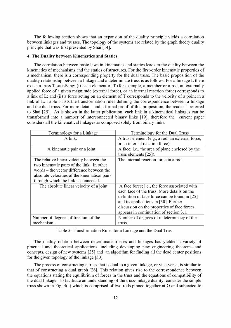
4. The Duality between Kinematics and Statics
The correlation between basic laws in kinematics and statics leads to the duality between the kinematics of mechanisms and the statics of structures. For the first-order kinematic properties of a mechanism, there is a corresponding property for the dual truss. The basic proposition of the duality relationship between a linkage and a determinate truss is as follows. For a linkage L there exists a truss T satisfying: (i) each element of T (for example, a member or a rod, an externally applied force of a given magnitude (external force), or an internal reaction force) corresponds to a link of L; and (ii) a force acting on an element of T corresponds to the velocity of a point in a link of L. Table 5 lists the transformation rules defining the correspondence between a linkage and the dual truss. For more details and a formal proof of this proposition, the reader is referred to Shai [25]. As is shown in the latter publication, each link in a kinematical linkages can be transformed into a number of interconnected binary links [19], therefore the current paper considers all the kinematical linkages as composed solely from binary links.
Terminology for a Linkage Terminology for the Dual Truss
A link. A truss element (e.g., a rod, an external force, or an internal reaction force).
A kinematic pair or a joint. A face; i.e., the area of plane enclosed by the truss elements [25]).
The relative linear velocity between the two kinematic pairs of the link. In other words – the vector difference between the absolute velocities of the kinematical pairs through which the link is connected.
The internal reaction force in a rod.
The absolute linear velocity of a joint. A face force; i.e., the force associated with each face of the truss. More details on the definition of face force can be found in [25] and its applications in [30]. Further discussion on the properties of face forces appears in continuation of section 3.1.
Number of degrees of freedom of the mechanism.
Number of degrees of indeterminacy of the truss.
Table 5. Transformation Rules for a Linkage and the Dual Truss.
The duality relation between determinate trusses and linkages has yielded a variety of practical and theoretical applications, including developing new engineering theorems and concepts, design of new systems [25] and an algorithm for finding all the dead center positions for the given topology of the linkage [30].
The process of constructing a truss that is dual to a given linkage, or vice-versa, is similar to that of constructing a dual graph [26]. This relation gives rise to the correspondence between the equations stating the equilibrium of forces in the truss and the equations of compatibility of the dual linkage. To facilitate an understanding of the truss-linkage duality, consider the simple truss shown in Fig. 4(a) which is comprised of two rods pinned together at O and subjected to

13
the external force 2Pr
acting at this point. The three elements of the truss are rod 3, rod 4, and
the external force 2Pr
and the four faces of the truss (see Table 5) are denoted as Q, R, S, and T.
(a) A Simple Truss (the Dual Linkage is Superimposed). (b) The Dual Linkage.
Fig. 4. An Example of the Truss-Linkage Duality.
Since the internal reaction forces in the truss must satisfy the condition of equilibrium [27]
then the external force can be written as
2 3 4P F F= +r r r
(21)
where 3 4F and Fr r
are the internal reaction forces in rods 3 and 4, respectively. The dual linkage can be obtained from the transformation rules that are presented in Table 5. The result is a planar four-bar linkage comprised of a ground link 1, an input (or driving) link 2′ , a coupler link 3′ and an output link 4′ , as shown in Fig. 4(b). The four links are pinned together and links 2′ and 4′ are pinned to the ground link at points 2O and 4O , respectively. Note that links 2′ , 3′ and 4′ correspond to the elements 2, 3 and 4 of the truss, respectively, such that each link is perpendicular to the corresponding element in the truss, as illustrated in Fig. 4(a). This construction guarantees that the direction of a force in a member of the truss is parallel to either the absolute velocity of a joint or the relative velocity between two joints in a link of the dual linkage; i.e., there is a geometrical isomorphism between the truss and the dual linkage. Since the truss can be scaled up or down without affecting the magnitudes of the internal forces then the lengths of the links of the dual linkage can also be scaled up or down without affecting the angular velocities of the links [18].
In addition, there is a topological isomorphism between the elements of the truss and the links of the dual linkage. To illustrate this, consider pin A which connects the input link 2′ and the coupler link 3′ , see Fig. 4(b). The linear velocity of pin A can be written as
BA A/BV V V= +r r r
(22)
A comparison of Equations (21) and (22) shows the topological isomorphism between the elements in the truss and the links in the dual linkage. The conclusion is that there is a correspondence between the forces in the truss elements (due to the external force 2P
r) and the
2O ′
4O ′ A
B
3 4
2
Q
AVr
2′
1
1
O
3′ 4′
1
1
11
S
T
R
2′ωr
2Pr

14
linear velocities of points in the links of the dual linkage (due to the input angular velocity 2ωr ).
This correspondence reflects the geometrical isomorphism and the topological isomorphism between the two systems.
A face force, which is defined in Table 5, is the most suitable entity to introduce equimomental lines into the static analysis of a truss. This force variable is associated with each face of the truss and can be considered the multi-dimensional expansion of the mesh-currents in an electronic circuit [25]. An internal reaction force acting in a member of a simple truss (denoted as j) can be written as
j R LF F F= −r r r
(23)
where RFr
and LFr
are the face forces of the two adjacent faces on the right and left sides, respectively, of the truss member. The equimomental line of the two face forces coincides with the vector difference of the two forces (see Section 2). Therefore, the equimomental line of two adjacent face forces coincides with the line of the rod, the line of action of the external force, or the line of action of the internal reaction force separating the two faces. To indicate the importance of a face force, Table 6 lists a number of dual properties between a planar mechanism and a truss. The relative instant center of two links connected by a revolute joint is coincident with the revolute joint.
The equimomental line of two adjacent face forces is the line which separates the two face forces.
The ground link. The reference face, namely one of the faces of the truss, where without loss of consistency the face force is chosen to be zero. Usually, the outside area of the truss is chosen to be the reference face.
The input (or driving) link. The face force whose value is given. In general, this is the face force in the face located on one side of the external force.
If the relative instant center Iij is coincident
with the absolute instant center I1i then the
linkage is immobile (or instantaneously locked).
If the corresponding equimomental line mxy is coincident with the equimomental
line mzy then the truss is not rigid.
The linkage is mobile if, and only if, there exists a set of all possible instant centers satisfying the Aronhold-Kennedy theorem.
A truss is stable if, and only if, there exists a set of all possible equimomental lines that satisfy the equimomental line theorem.
Table 6. Dual Properties of a Mechanism and a Truss.
The following section will present an original graphical technique, referred to here as the
dual Kennedy circle, to locate the unknown equimomental lines of a simple truss. After the locations of the equimomental lines are known then the face forces and the other unknown forces acting on the truss can be determined. An advantage of this technique, compared to analytical techniques, is that the internal reaction force in a specified rod can be obtained directly without the need to evaluate internal reaction forces in other rods of the truss. Finally, the section reviews a method for employing instant centers to synthesize a four-bar linkage and shows how this technique can be transformed to a method for synthesis in statics.

15
5. A Transformation Between Kinematics and Statics
The general principles of the kinematics of a mechanism that stem directly from the properties of instant centers are presented in the left-hand column of Table 7. The right-hand column of this table presents a transformation of these properties to statics.
Summary of the technique to find the secondary instant centers of a mechanism: 1. Map all the kinematic pairs as the instant centers of the connected links. 2. Find a set of four links (say 2, 3, 4, and 5) for which the relative instant centers I23, I34, I25 , and I45 are known. 3. The point of intersection of the line connecting instant centers I23 and I34, and the line connecting instant centers I25 and I45 is the instant center I24. 4. Repeat this procedure to locate all the unknown instant centers. To facilitate the application of this method, use the Kennedy circle as follows. Associate each link with a vertex on the circle. If the location of the instant center between two links is known then connect the two corresponding vertices with an edge. Step 2 is the search for a quadrangle formed by the edges in the circle, while step 3 results in the addition of a diagonal to that quadrangle.
Summary of the technique to find the equimomental lines of a simple truss: 1. Map all the rods as the equimomental lines of the faces they separate.
2. Find a set of four face forces (say x, y, z, and w) for which the equimomental lines mxy , myz , mwx , and mwz , are known. 3. The line connecting the point of intersection of equimomental lines mxy and
myz , and the point of intersection of
equimomental lines mwx and mwz is the equimomental line is mxz. 4. Repeat this procedure to locate all the unknown equimomental lines. To facilitate the application of this method, use the dual Kennedy circle as follows. Associate each face with a vertex on the circle. If the location of the equimomental line between two face forces is known then connect the two corresponding vertices with an edge. Step 2 is the search for a quadrangle formed by the edges in the circle, while step 3 results in the addition of a diagonal to the quadrangle.
The angular velocity of link i can be written in terms of the specified angular velocity of the input link 2 as
12 2i2
1i 2i
I II Iiω ω= ± (24)
where 1i 2iI I and 12 2iI I are the distances between instant centers 1i 2iI and I and between instant centers 12 2iI and I , respectively. Equation (24) takes advantage of the fact that the points on two links, which are coincident with the relative instant center of the two links, have the same linear velocity.
The face force of face i can be written in terms of the face force of the specified external force 2 as
12 2i2
1i 2i
m mF Fm mi = ± (25)
where 1i 2im m and 12 2im m are the perpendicular distances from an arbitrary point on the relative equimomental line 2im to the absolute equimomental lines 12m and 1im , respectively. Equation (25) takes advantage of the fact that two co-planar forces apply the same moment at each point on the equimomental line of these two forces.
Table 7. Transforming a Method from Kinematics to Statics.
Sign convention for Eq. (24): Use the negative sign if the relative instant center 2iI lies between the two absolute instant centers 12I and 1iI and use the positive sign otherwise.

16
The sign convention for Eq. (25) can be systematically obtained from the sign convention for Eq. (24) through the duality relation. The locations of the absolute instant centers with respect to the location of the relative instant center, in statics becomes the orientation of the forces with respect to the two half-planes into which the equimomental line cuts the plane. Accordingly, the sign convention for Eq. (25) is: Use the positive sign if the two forces F1 and F2, acting along the absolute equimomental lines m1i and m2i respectively, are oriented from the same half-plane created by the relative equimomental line m12 to the second half-plane, and use the negative sign otherwise.
To illustrate the technique presented in the right-hand column of Table 7 consider the simple truss shown in Fig. 5(a), in which the common assumption of pinned joints is implied. The truss is subjected to a known external force P
r which acts at the pin connecting the five members (or
rods) 5, 6, 8, 9 and 11.
Fig. 5(a). The Idealized Truss.
A typical statics problem is to determine the internal reaction force in a particular rod of the idealized truss. For the purposes of illustration, assume that the problem is to determine the internal reaction force in the lower rod 7. Recall that a conventional analytical approach to solve a statically determinate truss problem is to write the force balance equations for the members of the truss. This produces a set of simultaneous linear equations which can easily be solved using a software package such as MATLAB or mathematica. However, this procedure affords no geometric insight and the internal forces in several of the rods are evaluated before the internal force in rod 7 can be obtained. Note that the graphical technique proposed here (i.e., the face force technique) does not require knowledge of the internal forces in the other rods in order to determine the internal force in a specified rod. This graphical technique is believed to be an original contribution to the literature and is similar to drawing the Aronhold-Kennedy circle to locate the secondary instant centers in a single-degree-of-freedom planar mechanism [20]. For this reason the technique is referred to as drawing the dual Kennedy circle.
The number of faces of this truss is n 9= and are denoted as A, B, C, D, E, F, G, P and O as shown in Fig. 5(b).
Fig. 5(b). The Faces of the Simple Truss.
BC D
F
G 7
4 10 14
6
Rr
132 3
58
9
11
12
E
A
P O
1
Pr
2
4
3
5
6
7 10
9
11
1213
14
8
Rr1
Pr

17
The total number of equimomental lines in the simple truss is
Ln (n 1) 9(9 1)n = 36
2 2− −
= = (26)
The number of known equimomental lines can be written as K R E Sn = n n n+ + (27a)
where the number of rods Rn = 13, the number of external forces acting on the truss En 1,= and the number of mobile supports Sn = 1. Therefore, the number of known equimomental lines is
Kn 13 1 1 15= + + = (27b) The number of unknown equimomental lines is
Un 36 15 21= − = (28) The known equimomental lines are represented by the solid lines on the dual Kennedy circle, see Fig. 6(a).
Figs. 6. The Dual Kennedy Circle.
From Eq. (23), the internal reaction force in rod 7 can be written as
7F F F= −G C
r r r (29a)
where FC
r and FG
r are the face forces of the two adjacent faces C and G, respectively. The
magnitude of these two adjacent face forces can be written from Eq. (25), see Table 7, as PC PO PG PO
PC CO PG GO
m m m mF P and F Pm m m m
= ± = ±C G (29b)
where PC POm m and PC COm m are the perpendicular distances from an arbitrary point on the equimomental line PCm to the equimomental lines POm and COm , respectively, and PG POm m and
PG GOm m are the perpendicular distances from an arbitrary point on the equimomental line PGm
to the equimomental lines POm and GOm .
P
A B
C
D
E F
G
O
P
A B
C
D
E F
G
O
P
A B
C
D
E F
G
O
P
A B
C
D
E F
G
O
(c) The Equimomental Line PCm . (d) The Equimomental Line COm .
(a) The Known Equimomental Lines. (b) The Equimomental Line PGm .
18
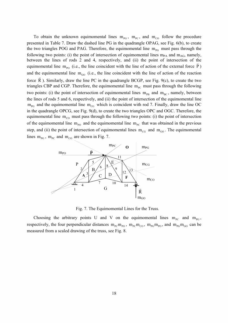
To obtain the unknown equimomental lines PGm , PCm , and COm follow the procedure presented in Table 7. Draw the dashed line PG in the quadrangle OPAG, see Fig. 6(b), to create the two triangles POG and PAG. Therefore, the equimomental line PGm must pass through the following two points: (i) the point of intersection of equimomental lines mPA and mAG, namely, between the lines of rods 2 and 4, respectively, and (ii) the point of intersection of the equimomental line POm (i.e., the line coincident with the line of action of the external force P
r)
and the equimomental line GOm (i.e., the line coincident with the line of action of the reaction
force Rr
). Similarly, draw the line PC in the quadrangle BCGP, see Fig. 9(c), to create the two triangles CBP and CGP. Therefore, the equimomental line PCm must pass through the following two points: (i) the point of intersection of equimomental lines PBm and BCm , namely, between the lines of rods 5 and 6, respectively, and (ii) the point of intersection of the equimomental line
PGm and the equimomental line CGm which is coincident with rod 7. Finally, draw the line OC in the quadrangle OPCG, see Fig. 9(d), to create the two triangles OPC and OGC. Therefore, the equimomental line COm must pass through the following two points: (i) the point of intersection of the equimomental line POm and the equimomental line PCm that was obtained in the previous step, and (ii) the point of intersection of equimomental lines CGm and GOm . The equimomental lines PGm , PCm and COm are shown in Fig. 7.
Fig. 7. The Equimomental Lines for the Truss.
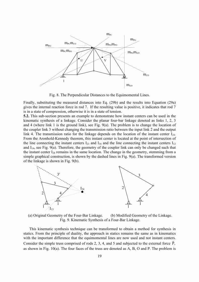
Choosing the arbitrary points U and V on the equimomental lines PCm and PGm , respectively, the four perpendicular distances PC POm m , PC COm m , PG POm m , and PG GOm m can be measured from a scaled drawing of the truss, see Fig. 8.
Pr
BC D F
G
mPC mPG
mCO 74 10 14
6132
3
5 8
9
11
12
E
A
P
O
mCG
mPO
Rr
mGO
1
19
Fig. 8. The Perpendicular Distances to the Equimomental Lines. Finally, substituting the measured distances into Eq. (29b) and the results into Equation (29a) gives the internal reaction force in rod 7. If the resulting value is positive, it indicates that rod 7 is in a state of compression, otherwise it is in a state of tension. 5.2. This sub-section presents an example to demonstrate how instant centers can be used in the kinematic synthesis of a linkage. Consider the planar four-bar linkage denoted as links 1, 2, 3 and 4 (where link 1 is the ground link), see Fig. 9(a). The problem is to change the location of the coupler link 3 without changing the transmission ratio between the input link 2 and the output link 4. The transmission ratio for the linkage depends on the location of the instant center I24. From the Aronhold-Kennedy theorem, this instant center is located at the point of intersection of the line connecting the instant centers I23 and I34 and the line connecting the instant centers I12 and I14, see Fig. 9(a). Therefore, the geometry of the coupler link can only be changed such that the instant center I24 remains in the same location. The change in the geometry, stemming from a simple graphical construction, is shown by the dashed lines in Fig. 9(a). The transformed version of the linkage is shown in Fig. 9(b).
(a) Original Geometry of the Four-Bar Linkage. (b) Modified Geometry of the Linkage.
Fig. 9. Kinematic Synthesis of a Four-Bar Linkage.
This kinematic synthesis technique can be transformed to obtain a method for synthesis in statics. From the principle of duality, the approach in statics remains the same as in kinematics with the important difference that the equimomental lines are now used and not instant centers. Consider the simple truss comprised of rods 2, 3, 4, and 5 and subjected to the external force P,
r
as shown in Fig. 10(a). The four faces of the truss are denoted as A, B, O and P. The problem is
mPC
mCO
mGO
mPO
mPG
1
mPCmCO
mPCmPO mPGmGO
mPGmPO
VU
2
3
4
3′
I24
I13
1
2
4
3
1
11

20
to perform the re-position of rod 4, as indicated by the dashed line and denoted as 4′ , without affecting the ratio of force P
r to the internal force in rod 5. Such a requirement arises when
during the truss construction, it is discovered that the current position of rods is incompatible with the environmental constraints and should be relocated without affecting other static properties of the truss. Note that this internal force can be determined by the face force B; i.e., the location of the equimomental lines BPm and BOm uniquely determines the internal force in rod 5. The equimomental line BOm is known since it coincides with rod 5. The equimomental
line BPm can be obtained by drawing a line between the point of intersection of force Pr
and rod 5, and the point of intersection of rods 2 and 4, as shown in Fig. 10(b). Since the synthesis condition is to maintain the same internal force in rod 5 then the geometry of the truss must be modified. The changes, however, must ensure that the equimomental lines BOm and BPm remain in the same positions. One possible solution is to change the orientation of rod 2, denoted as 2′ , such that the point of intersection of 2′ with rod 4′ will remain on the equimomental line BPm , see Fig. 10(b). The geometry of the modified truss, denoted by rods 2′ , 3, 4′ , and 5, is shown in Fig. 10(c).
Fig. 10. The Synthesis Technique Applied to a Simple Truss.
The following section will illustrate the correspondence between (i) a non-rigid truss and the
dual linkage; and (ii) the equimomental lines in the double flier eight-bar linkage in an arbitrary configuration and a singular configuration. The examples use the theorems and properties of a truss and the dual linkage, presented in the previous sections, to investigate a special configuration of the truss and a singular configuration of the double flier eight-bar linkage.
6. Special Configurations The problem of finding dead-point positions of engineering systems is widely reported in the literature [29], due to its importance in many fields of engineering practice. Examples appearing in this section deal with identification of such configurations of trusses and mechanisms through the concepts described above. It should be noted that the problems introduced in this section are useful not only for finding whether the given configuration of the system is in a singular position, but also to identify the dependence between the locations system elements which causes it to be in a singular position. In engineering practice this problem is known to be complex.
3
2 5
O P
A
B
43
2
5
O P
A
B
4
4′2′
mPB
3
5
O P
A
B
4′
2′
(a) Original Truss and the New Position of Rod 4.
(b) Equimomental Lines of the Original Truss.
(c) Geometry of the Modified Truss.
(mPA; mAB) (mP0; m0B)
4′
Pr
Pr
Pr
1′ 1 1′
1
1 1′1′
1
1
1 1
1′

21
6.1. A Determinate Truss. Consider the truss shown in Fig. 11(a) which is subjected to a known external force 2P
r acting at the pin connecting rods 4, 6 and 7. Note that this truss is in a special
configuration; i.e., rods 3, 7 and 8 (or the extension of the three rods) intersect at a single point. The five faces of this truss will be denoted as A, B, C, D and E. Faces B and D are adjacent faces separated by rod 8, therefore, the equimomental line BDm is coincident with rod 8, as shown in Fig. 11(b). Similarly, the equimomental line DEm is coincident with rod 3, the equimomental line
ABm is coincident with rod 7, and the equimomental line AEm is coincident with the line of
action of the external force 2Pr
.
(a) The Truss. (b) The Equimomental Line BEm .
Fig. 11. The Rigidity of the Truss.
According to the dual statics theorem, the equimomental line BEm (for the two face forces B and E) is obtained by connecting the points of intersection of: (i) the equimomental lines BDm and DEm ; and (ii) the equimomental lines ABm and AEm . Therefore, the equimomental line BEm is the line connecting the point of intersection of rods 3, 7 and 8 (or the rods extended) and the pin connecting rods 4, 6, and 7. In other words, the equimomental line BEm is coincident with rod 7 (or the equimomental line ABm ), see Fig. 5(b). The conclusion is that the truss is unstable in this configuration (see row 4 of Table 6).
The dual linkage, superimposed on the truss in Fig. 12(a) and shown separately in Fig. 12(b), is a Stephenson-III six-bar linkage in a special configuration; i.e., links 3, 4 and 6 (or the extensions of the links) intersect at a single point. According to the Aronhold-Kennedy theorem this unique point is the instant center for the coupler link 5 (i.e., 15I ), see Fig. 12(c). Recall that the instant center 13I is defined as the point of intersection of the line passing through the instant centers 12I and 23I and the line passing through the instant centers 15I and 35I . Therefore, the instant center 13I is coincident with the pin that connects links 2 and 3; i.e., 13I is coincident with
23I , as shown in Fig. 12(c). This implies that the dual linkage is instantaneously locked or immobile in this configuration (see row 4 of Table 6); i.e., the input angular velocity is zero. The only constraint for the linkage to be in this special configuration, commonly referred to as a
7
8
3 4 5
6
P2r
E
C
D mAB
mBD
mDE 4 5
6
mAE E
C
D
mBE
A
B B
A
3
1 1
1 1
1
8
7
1

22
dead-center position [15, 20], is that the instant center 15I be located on link 3 (or link 3 extended).
(a) The Non-Rigid Truss. (b) The Dual Linkage.
(c) Instant Center 13I is Coincident with Instant Center 23I .
Fig. 12. The Dual Linkage in a Dead-Center Position. 6.2. The Double Flier Eight-Bar Linkage. This single-degree-of-freedom planar linkage in shown in an arbitrary configuration in Fig. 13(a). The seven faces of the dual truss will be denoted as A, B, C, D, E, F, and G, and for convenience are shown on Fig. 13(a).
3 5
6
4
2
1
I15, I25
I45
I56
1
1
I23, I13
2ωr
I35
I16
I12
I14
3 5
6
4
2A
1
B
C
D
1
1
1
1
1
1
1
2ωr
P2r
I16

23
Fig. 13(a). Double Flier Eight-Bar Linkage in an Arbitrary Configuration. From the equimomental line theorem, see Table 7, the three equimomental lines defined by faces A, F and D (i.e., AFm , FDm and ADm ) must intersect at a single point. Link 3 separates faces A and F, therefore, the line along link 3 is the equimomental line AFm . Similarly, link 4 separates faces D and F, therefore, the line along link 4 is the equimomental line FDm . Therefore, the equimomental line ADm must pass through the point of intersection of links 3 and 4. From a similar argument, the equimomental line ADm must also pass through the point of intersection of links 11 and 13. Therefore, the equimomental line ADm is the line connecting these two points of intersection, see Fig. 13(a). In the same manner, the equimomental line ABm must pass through the point of intersection of links 8 and 11, and the point of intersection of link 7 and the equimomental line ADm . Finally, the equimomental line BFm (if it exists for the double flier eight-bar linkage in this configuration) must pass through the points of intersections of: (i) links 6 and 14, (ii) links 4 and 7, and (iii) the equimomental line ABm and link 3. Note that these three points, marked with circles in Fig. 13(a), do not lie on the same straight line. Therefore, the equimomental line BFm does not exist for the linkage in this configuration. The conclusion is that the linkage is instantaneously movable in the given configuration; i.e., the linkage has an instantaneous mobility of one.
Now consider the double flier eight-bar linkage in the configuration shown in Fig. 13(b).
2
14
3 4
5
6
7
8
9
10
11
12
13
mAD
mAB
A
BC
D
E
F
G
1
1
mAF
mFD
1

24
Fig. 13(b). The Equimomental Line BFm for a Singular Configuration. Note that the three points of intersections of: (i) links 6 and 14, (ii) links 4 and 7, and (iii) the equimomental line ABm and link 3, again marked with circles in Fig. 13(b), now lie on the same straight line; i.e., the equimomental line BFm . This indicates that the linkage is in a singular configuration. The linkage can resist externally applied forces and instantaneously constitutes a structure; i.e., the instantaneous mobility is zero. 7. Conclusions
The paper presents the duality relation between the domains of kinematics and statics through two integrated levels: (i) the level of correlation between the basic concepts and theorems underlying these fields, and (ii) the level of duality between specific engineering systems. The paper introduces the static counterpart of a technique that is used in kinematics to obtain the instantaneous center of zero velocity of a linkage. The technique is referred to as the equimomental line which exists for two arbitrary co-planar forces. Two theorems are presented based on the duality between equimomental lines and instantaneous centers. The first theorem states that the three equimomental lines defined by three co-planar forces must intersect at a unique point. The second theorem states that the equimomental line for two co-planar forces acting in a truss with two degrees of indeterminacy, must pass through a unique point. Also, a graphical technique to locate the instant centers of an indeterminate mechanism is extended to investigate determinate trusses. The paper also presents a dual form of the well-known
9
11
10
12
4
142 3
5
13
67
8
mAD
mAB
mBF
2ωr
1
1
1

25
Aronhold-Kennedy theorem in kinematics which is referred to as the equimomental line theorem.
The practical examples presented in this paper emphasis the duality that exists between kinematics and statics. For instance, fundamental principles in kinematics can be used to check the stability of determinate trusses and principles in statics can be used to check the singularity of linkages. The results of this paper afford engineers from both domains the opportunity to solve common problems using these new concepts. In addition, research groups in kinematics and statics will be able to share their knowledge and expedite their research work. Since the paper operates on the edge between kinematics and statics, the results presented in this paper have great potential for practical applications. There is reason to believe that the duality relation can be applied to additional types of engineering systems. Examples include deployable structures which have attracted the attention of the aeronautics and astronautics community and tensegrity structures which have attracted the attention of the robotics and biological communities [28].
The authors believe that this paper makes a significant contribution to the theory of duality between kinematics and statics and a stronger contribution to the teaching of this theory. The authors hope that this duality will be developed further in order to derive new theorems in both the kinematics of mechanisms and in the statics of all types of structures. The authors continue to explore this possibility and a future paper will present several new concepts in the kinematic analysis and synthesis of planar and spatial mechanisms and the statics of structures consisting of one, two, and three-dimensional components. Future work will also include analytical techniques to complement the graphical techniques that are the primary focus of this paper. References 1. Girvin, S.M., 1996, “Duality in Perspective,” Science, Vol. 274, Issue 5287, pp. 524-525,
October. 2. Pedoe, D., 1963, An Introduction to Projective Geometry, Pergamon Press, Oxford,
England. 3. Hsia, L. M., and Yang, A. T., 1981, “On The Principle of Transference in Three-
Dimensional Kinematics,” ASME Journal of Mechanical Design, Vol. 103, No. 3, pp. 652-656.
4. Phillips, J., 1984, Freedom in Machinery, Vol. 1, Cambridge University Press, England. 5. Pennock, G.R., and Yang, A.T., 1985, “Application of Dual-Number Matrices to the
Inverse Kinematics Problem of Robot Manipulators,” ASME Journal of Mechanisms, Transmissions, and Automation in Design, Vol. 107, No. 2, June, pp. 201-208.
6. Tarnai, T., 1989, “Duality between Plane Trusses and Grillages,” International Journal of Solids and Structures, Vol. 25, No. 12, pp. 1395-1409.
7. Davies, T., 1983, “Mechanical Networks – III, Wrenches on Circuit Screws,” Mechanism and Machine Theory, Vol. 18, No. 2, pp. 107-112.
8. Waldron, K.J., and Hunt K.H., 1991, “Series-Parallel Dualities in Actively Coordinated Mechanisms,” International Journal of Robotics Research, MIT Press, Vol. 10, No. 5, pp. 473-480.
9. Gosselin, F., and Lallemand, J-P., 2001, “A New Insight into the Duality between Serial and Parallel Non-Redundant and Redundant Manipulators,” Robotica, Vol. 19, pp. 365-370.
10. Duffy, J., 1996, Statics and Kinematics with Applications to Robotics, Cambridge University Press. New York.
11. Davidson, J. K., and Hunt, K. H., 2004, Robots and Screw Theory: Applications of Kinematics and Statics to Robotics, Oxford University Press, Inc., New York.

26
12. Ball, R. S., 2000, The Theory of Screws, Cambridge University Press, England. (Originally published in 1876 and revised by the author in 1900; now reprinted with an introduction by H. Lipkin and J. Duffy).
13. McGuire, W., Gallagher, R.H., and Ziemian, R.D., 2000, Matrix Structural Analysis, Second Edition, John Wiley & Sons, Inc., New York.
14. Shai, O., 2001, “The Duality Relation between Mechanisms and Trusses,” Mechanism and Machine Theory, Vol. 36, No. 3, pp. 343-369.
15. Foster, D.E., and Pennock, G.R., 2003, “A Graphical Method to Find the Secondary Instantaneous Centers of Zero Velocity for the Double Butterfly Linkage,” ASME Journal of Mechanical Design, Vol. 125, No. 2, pp. 268-274.
16. Foster, D.E., and Pennock, G.R., 2005, “Graphical Methods to Locate the Secondary Instant Centers of Single-Degree-of-Freedom Indeterminate Linkages,” ASME, Journal of Mechanical Design, Vol. 127, No. 2, pp. 249-256.
17. Hartenberg, R.S., and Denavit, J., 1964, Kinematic Synthesis of Linkages, McGraw-Hill Book Co., New York.
18. Waldron, K.J., and Kinzel, G.L., 2004, Kinematics, Dynamics, and Design of Machinery, Second Edition, John Wiley and Sons, Inc., New York, Chaps. 2 and 4.
19. Norton, R.L., 2001, Design of Machinery, McGraw-Hill Book Company, Inc., New York. 20. Uicker, J.J., Jr., Pennock, G.R., and Shigley, J.E., 2003, Theory of Machines and
Mechanisms, Third Edition, Oxford University Press, Inc., New York. 21. Erdman, A.G., and Sandor, G.N., 1997, Mechanism Design – Analysis and Synthesis, Vol.
1, Third Edition, Prentice-Hall, Inc., Upper Saddle River, New Jersey. 22. Hall, A. S., Jr., 1986, Kinematics and Linkage Design, Waveland Press, Inc., Prospect
Heights, Illinois. (Originally published by Prentice-Hall, Inc., 1961). 23. Bagci, C., 1983, “Turned Velocity Image and Turned Velocity Superposition Techniques
for the Velocity Analysis of Multi-Input Mechanisms Having Kinematic Indeterminacies,” Mechanical Engineering News, Vol. 20, No. 1, February, pp. 10-15.
24. Pennock, G.R., and Kinzel, E.C., 2004, “Path Curvature of the Single Flier Eight-Bar Linkage,” ASME Journal of Mechanical Design, Vol. 126, No. 3, pp. 470-477.
25. Shai, O., 2002, “Utilization of the Dualism between Determinate Trusses and Mechanisms,” Mechanism and Machine Theory, Vol. 37, No. 11, pp. 1307-1323.
26. Swamy, M.N., and Thulasiraman, K., 1981, Graphs: Networks and Algorithms, John Wiley and Sons, Inc., New York.
27. West, H.H., 1993, Fundamentals of Structural Analysis, John Wiley & Sons, New York. 28. Ingber, D. E., 1998, “The Architecture of Life,” Scientific American, January, pp. 48-57. 29. Yan, H-S., and Wu, L-L., 1989, “On The Dead-Center Positions of Planar Linkage
Mechanisms,” ASME Journal of Mechanisms, Transmissions, and Automation in Design, Vol. 111, No. 1, pp. 40-46.
30. Shai O. and Polansky I., "Finding Dead Point Positions of Linkages through Graph Theoretical Duality Principle", accepted for publication in ASME – Journal of Mechanical Design, 2005.