a study of the effectiveness of local exhaust …eprints.uthm.edu.my/5446/1/ng_chee_seng.pdf · i a...
TRANSCRIPT

i
A STUDY OF THE EFFECTIVENESS OF LOCAL EXHAUST VENTILATION
(LEV) IN TRAINING FACILITIES BUILDING USING COMPUTATIONAL
FLUID DYNAMICS (CFD) APPROACH
NG CHEE SENG
A thesis submitted in fulfillment of the requirements for the award of the Degree of
Master of Mechanical Engineering
Faculty of Mechanical and Manufacturing Engineering
Universiti Tun Hussein Onn Malaysia
December 2013
vi
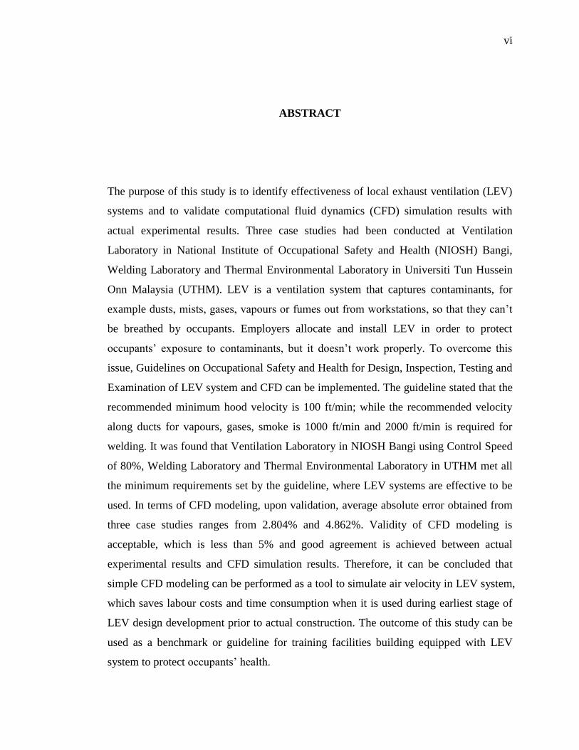
ABSTRACT
The purpose of this study is to identify effectiveness of local exhaust ventilation (LEV)
systems and to validate computational fluid dynamics (CFD) simulation results with
actual experimental results. Three case studies had been conducted at Ventilation
Laboratory in National Institute of Occupational Safety and Health (NIOSH) Bangi,
Welding Laboratory and Thermal Environmental Laboratory in Universiti Tun Hussein
Onn Malaysia (UTHM). LEV is a ventilation system that captures contaminants, for
example dusts, mists, gases, vapours or fumes out from workstations, so that they can‟t
be breathed by occupants. Employers allocate and install LEV in order to protect
occupants‟ exposure to contaminants, but it doesn‟t work properly. To overcome this
issue, Guidelines on Occupational Safety and Health for Design, Inspection, Testing and
Examination of LEV system and CFD can be implemented. The guideline stated that the
recommended minimum hood velocity is 100 ft/min; while the recommended velocity
along ducts for vapours, gases, smoke is 1000 ft/min and 2000 ft/min is required for
welding. It was found that Ventilation Laboratory in NIOSH Bangi using Control Speed
of 80%, Welding Laboratory and Thermal Environmental Laboratory in UTHM met all
the minimum requirements set by the guideline, where LEV systems are effective to be
used. In terms of CFD modeling, upon validation, average absolute error obtained from
three case studies ranges from 2.804% and 4.862%. Validity of CFD modeling is
acceptable, which is less than 5% and good agreement is achieved between actual
experimental results and CFD simulation results. Therefore, it can be concluded that
simple CFD modeling can be performed as a tool to simulate air velocity in LEV system,
which saves labour costs and time consumption when it is used during earliest stage of
LEV design development prior to actual construction. The outcome of this study can be
used as a benchmark or guideline for training facilities building equipped with LEV
system to protect occupants‟ health.

vii
ABSTRAK
Kajian ini bertujuan untuk mengenalpasti keberkesanan sistem pengudaraan ekzos
setempat (LEV) dan mengesahkan keputusan perkomputeran dinamik bendalir (CFD)
dengan keputusan eksperimen sebenar. Tiga kajian kes telah dijalankan di Makmal
Ventilasi yang terletak di Institut Keselamatan dan Kes Pekerjaan Negara (IKKPN)
Bangi; Makmal Kimpalan dan Makmal Persekitaran Terma yang terletak di Universiti
Tun Hussein Onn Malaysia (UTHM). LEV ialah satu sistem ventilasi yang menangkap
bahan-bahan tercemar, seperti habuk, kabus, gas-gas, wap atau asap keluar dari tempat
kerja, supaya bahan-bahan tercemar ini tidak dapat disedut oleh penghuni-penghuni.
Majikan-majikan memperuntukkan dan memasang LEV supaya melindungi pekerja-
pekerja daripada terdedah kepada bahan-bahan tercemar, tetapi LEV tidak berfungsi
dengan betul. Untuk mengatasi isu ini, garis panduan “Guidelines on Occupational
Safety and Health for Design, Inspection, Testing and Examination of LEV system” dan
CFD boleh dilaksanakan. Garis panduan tersebut menyatakan bahawa halaju minimum
tudung yang dicadangkan ialah 100 kaki/minit; manakala halaju sepanjang saluran untuk
wap, gas-gas, asap yang dicadangkan ialah 1000 kaki/minit dan 2000 kaki/min untuk gas
kimpalan. Keputusan didapati bahawa Makmal Ventilasi di IKKPN Bangi yang
menggunakan Halaju Kawalan sebanyak 80%, Makmal Kimpalan dan Makmal
Persekitaran Terma di UTHM mencapai semua keperluan minimum yang dicadangkan
oleh garis panduan tersebut, di mana sistem-sistem LEV tersebut adalah berkesan untuk
digunakan. Dari segi permodelan CFD, selepas pengesahan dilakukan, didapati julat
ralat purata diperolehi daripada tiga kajian kes ialah dari 2.804% sehingga 4.862%.
Kesahihan permodelan CFD boleh diterima, dimana ia adalah jurang daripada 5%. Oleh
itu, permodelan CFD yang mudah boleh digunakan sebagai satu alat perisian untuk

viii
mensimulasi halaju udara dalam sistem LEV, dimana kos buruh dapat dijimatkan dan
penggunaan masa dapat dikurangkan apabila ia digunakan semasa peringkat terawal
pembangunan rekabentuk LEV sebelum pembinaan sebenar dilakukan. Hasil kajian ini
dapat digunakan sebagai garis panduan untuk bangunan kemudahan latihan yang
dilengkapi dengan sistem LEV untuk melindungi kesihatan pekerja-pekerja.

ix
CONTENTS
CHAPTER TOPIC PAGE
DEDICATION iv
ACKNOWLEDGEMENT v
ABSTRACT vi
ABSTRAK vii
CONTENTS ix
LIST OF TABLES xiv
LIST OF FIGURES xvi
LIST OF SYMBOLS AND ABBREVIATIONS xxi
LIST OF APPENDICES xxiii
1. INTRODUCTION 1
1.1 Background of Problem 2
1.2 Objective of Study 4
1.3 Problem Statement of Study 4
1.4 Scope of Study 5
1.5 Significance of Study 6

x
2. THEORY AND LITERATURE REVIEW 7
2.1 Local Exhaust Ventilation (LEV) 7
2.1.1 Hood 8
2.1.2 Duct 10
2.1.3 Fan 11
2.2 Application of LEV System 12
2.2.1 Engineering Control of Disc Sander in a
Plant 12
2.2.2 Engineering Control in Welding Industry 13
2.2.3 Engineering Control of Exhaust Hoods of
LEV System 15
2.2.4 Engineering Control of Wet Grinding,
Ventilated Grinding and Uncontrolled
Conventional Grinding in Construction
Industry 21
2.3 Computational Fluid Dynamics (CFD) 25
2.3.1 Boundary Conditions 27
2.3.2 Turbulence Model 31
2.4 LEV Simulation Using CFD 33
2.5 Summary 39

xi
3. METHODOLOGY 42
3.1 General Experimental Design 42
3.2 Flow Chart 43
3.3 Study Framework 44
3.4 Case Studies 45
3.4.1 First Case Study: Ventilation Laboratory in
National Institute for Occupational Safety
and Health (NIOSH) Bangi 45
3.4.2 Second Case Study: Welding Laboratory
in Universiti Tun Hussein Onn Malaysia
(UTHM) 48
3.4.3 Third Case Study: Thermal Environmental
Laboratory in UTHM 50
3.5 Instrumentation 53
3.6 Actual Experiment Methods 55
3.6.1 Measurement of Velocity Pressure (VP) 55
3.6.2 Computing Average Velocity from
Velocity Pressure Readings 61
3.7 CFD Simulation Techniques 62
3.7.1 Pre-processing 62
3.7.2 Solver 72
3.7.3 Post-processing 73
3.8 Computing Absolute Error Calculation from
Velocity Value 74

xii
4. RESULT AND DISCUSSION 75
4.1 Results of Actual Experiment at Ventilation
Laboratory in NIOSH Bangi, Selangor 76
4.1.1 Results of Actual Experiment at Ventilation
Laboratory in NIOSH Bangi Using
Speed Control of 20% 76
4.1.2 Results of Actual Experiment at Ventilation
Laboratory in NIOSH Bangi Using
Speed Control of 40% 79
4.1.3 Results of Actual Experiment at Ventilation
Laboratory in NIOSH Bangi Using
Speed Control of 60% 81
4.1.4 Results of Actual Experiment at Ventilation
Laboratory in NIOSH Bangi Using
Speed Control of 80% 84
4.2 Results of Actual Experiment at Welding
Laboratory in UTHM 86
4.3 Results of Actual Experiment at Thermal
Environmental Laboratory in UTHM 89
4.4 Validation of LEV at Ventilation Laboratory
in NIOSH Bangi, Selangor 92
4.4.1 Validation of LEV at Ventilation Laboratory
in NIOSH Bangi Using Speed Control
of 20% 92
4.4.2 Validation of LEV at Ventilation Laboratory
in NIOSH Bangi Using Speed Control
of 40% 93

xiii
4.4.3 Validation of LEV at Ventilation Laboratory
in NIOSH Bangi Using Speed Control
of 60% 94
4.4.4 Validation of LEV at Ventilation Laboratory
in NIOSH Bangi Using Speed Control
of 80% 95
4.5 Validation of LEV at Welding Laboratory in
UTHM 96
4.6 Validation of LEV at Thermal Environmental
Laboratory in UTHM 97
4.7 Discussion of Actual Experiments of LEV System 98
4.8 Discussion of CFD Validation of LEV System 103
5. CONCLUSION AND RECOMMENDATION 108
5.1 Conclusion 109
5.2 Contribution to Society 110
5.3 Recommendation for Future Work 111
REFERENCES 112
APPENDICES 117

xiv
LIST OF TABLES
TABLE TITLE PAGE
2.1 Quantitative collection efficiencies for each hood
(Old et al., 2008) 18
2.2 The difference between Wong et al.’s work and current
study’s work 35
2.3 Summary of past studies on LEV system 39
2.4 Summary of literature review on CFD 40
3.1 Recommended traverse insertion depths for round ducts
(Guidelines on Occupational Safety and Health for Design,
Inspection, Testing and Examination of LEV system, 2008) 57
3.2 An example of how insertion depths of pitot tube were
determined for round ducts using 10 insertion points 58
3.3 Nodes and elements of three case studies 70
4.1a Results of Actual Experiment using Speed Control of 20%
(Ventilation Laboratory in NIOSH Bangi) 77
4.1b Results of Actual Experiment using Speed Control of 20%
(Ventilation Laboratory in NIOSH Bangi) 77
4.2a Results of Actual Experiment using Speed Control of 40%
(Ventilation Laboratory in NIOSH Bangi) 79
4.2b Results of Actual Experiment using Speed Control of 40%
(Ventilation Laboratory in NIOSH Bangi) 80

xv
4.3a Results of Actual Experiment using Speed Control of 60%
(Ventilation Laboratory in NIOSH Bangi) 82
4.3b Results of Actual Experiment using Speed Control of 60%
(Ventilation Laboratory in NIOSH Bangi) 82
4.4a Results of Actual Experiment using Speed Control of 80%
(Ventilation Laboratory in NIOSH Bangi) 84
4.4b Results of Actual Experiment using Speed Control of 80%
(Ventilation Laboratory in NIOSH Bangi) 85
4.5a Results of Actual Experiment (Welding Laboratory in UTHM) 87
4.5b Results of Actual Experiment (Welding Laboratory in UTHM) 87
4.6a Results of Actual Experiment (Thermal Environmental
Laboratory in UTHM) 89
4.6b Results of Actual Experiment (Thermal Environmental
Laboratory in UTHM) 90
4.7 Validation of air velocity results with Speed Control of 20%
(Ventilation Laboratory in NIOSH Bangi) 92
4.8 Validation of air velocity results with Speed Control of 40%
(Ventilation Laboratory in NIOSH Bangi) 93
4.9 Validation of air velocity results with Speed Control of 60%
(Ventilation Laboratory in NIOSH Bangi) 94
4.10 Validation of air velocity results with Speed Control of 80%
(Ventilation Laboratory in NIOSH Bangi) 95
4.11 Validation of air velocity results (Welding Laboratory in UTHM) 96
4.12 Validation of air velocity results (Thermal Environmental
Laboratory in UTHM) 97
4.13 Hood velocity obtained in three case studies 98
4.14 Velocity along ducts in three case studies 99
4.15 Summary of overall LEV system effectiveness of all
three case studies 101
4.16 Range of flow rate measured for all three case studies 102
4.17 Average absolute error of all three case studies 107

xvi
LIST OF FIGURES
FIGURE TITLE PAGE
2.1 Common elements of a simple LEV system (Guidelines on
Occupational Safety and Health for Design, Inspection,
Testing and Examination of LEV system, 2008) 7
2.2 An example of enclosure hood (Guidelines on Occupational
Safety and Health for Design, Inspection, Testing and
Examination of LEV system, 2008) 8
2.3 Example of exterior hoods (Guidelines on Occupational
Safety and Health for Design, Inspection, Testing and
Examination of LEV system, 2008) 9
2.4 An example of ducts at Welding Laboratory in UTHM 10
2.5 Examples of fan used in LEV system (Guidelines on
Occupational Safety and Health for Design, Inspection,
Testing and Examination of LEV system, 2008) 11
2.6 Sketch of disc sander with LEV system (Mazzuckelli et al., 2004) 12
2.7 Small mixing ventilated exhaust hood (Old et al., 2008) 16
2.8 Large mixing ventilated booth-type exhaust hood
(Old et al., 2008) 16
2.9 Tracer gas capture test setup (Old et al., 2008) 17
2.10 Real-time evaluation of bench top exhaust hoods – control on /
control off (Old et al., 2008) 19

xvii
2.11 A 17.5 cm size uncontrolled conventional grinder
(Khanzadeh et al., 2007) 22
2.12 A 17.5 cm size wet grinder with water hose attached
(Khanzadeh et al., 2007) 23
2.13 A 15 cm LEV grinder with vacuum system
(Khanzadeh et al., 2007) 23
2.14 A region surrounded by a boundary
(STAR-CCM+ Tutorial Guide, 2009) 27
2.15 Three separate regions with three different boundaries
(STAR-CCM+ Tutorial Guide, 2009) 28
2.16 CFD simulations of food court center with four different
mechanical ventilation systems (Wong et al., 2006) 34
2.17 Initial configuration of simulation model of Case 1
(Mendez et al., 2008) 36
2.18 Five local ventilation outlets used for analysis. Three
outlets emanate from the roof (R1, R2, and R3) while two
from the floor (F1 and F2) (Inthavong et al., 2009) 37
3.1 Flow chart of this study 43
3.2 Framework of this study 44
3.3 Overview of LEV at Ventilation Laboratory in NIOSH Bangi 46
3.4 Speed Control panel of LEV at Ventilation Laboratory in
NIOSH Bangi 47
3.5 Nine locations where measurements were conducted at
Ventilation Laboratory in NIOSH Bangi 48
3.6 Overview of LEV at Welding Laboratory in UTHM 49
3.7 Seven locations where measurements were conducted at
Welding Laboratory in UTHM 50
3.8 Overview of LEV at Thermal Environmental Laboratory
in UTHM 51
3.9 Four locations where measurements were conducted at
Thermal Environmental Laboratory in UTHM 52
xviii
3.10 Anemometer VelociCalc Plus Meter Model 8386 53
3.11 Pitot tube 53
3.12 Insertion depths for round ducts (Guidelines on Occupational
Safety and Health for Design, Inspection, Testing and
Examination of LEV system, 2008) 56
3.13 Insertion measurement points for rectangular ducts
(Guidelines on Occupational Safety and Health for Design,
Inspection, Testing and Examination of LEV system, 2008) 57
3.14 Insertion depths of pitot tube for round ducts at Location 1
of Ventilation Laboratory LEV in NIOSH Bangi using
10 insertion points 59
3.15 Round duct of LEV at Ventilation Laboratory in Bangi NIOSH 60
3.16 Round duct of LEV at Welding Laboratory in UTHM 60
3.17 Rectangular duct of LEV at Thermal Environmental Laboratory
in UTHM 61
3.18 SolidWorks drawing board 63
3.19 Geometry model of LEV hood drawn using SolidWorks 63
3.20 LEV geometry model at Ventilation Laboratory in
NIOSH Bangi 64
3.21 LEV geometry model at Welding Laboratory in UTHM 65
3.22 LEV geometry model at Thermal Environmental
Laboratory in UTHM 65
3.23 ANSYS Workbench 66
3.24 Selecting CFX on ANSYS Workbench 67
3.25 Importing IGS file format to ANSYS CFX Workbench 67
3.26 Applying boundary conditions on LEV geometry model 68
3.27 Selecting turbulence model on LEV geometry model 69
3.28 Generating meshing on LEV geometry model at
Ventilation Laboratory in NIOSH Bangi 70
3.29 Generating meshing on LEV geometry model at
Welding Laboratory in UTHM 71
xix
3.30 Generating meshing on LEV geometry model at
Thermal Environmental Laboratory in UTHM 71
3.31 Iteration of CFD tool, ANSYS 72
3.32 Obtaining CFD results on ANSYS Workbench 73
4.1 Graph of velocities of each location at Ventilation Laboratory
in NIOSH Bangi using Speed Control of 20% 78
4.2 Graph of velocity profile at Ventilation Laboratory
in NIOSH Bangi using Speed Control of 20% 78
4.3 Graph of velocities of each location at Ventilation Laboratory
in NIOSH Bangi using Speed Control of 40% 80
4.4 Graph of velocity profile at Ventilation Laboratory
in NIOSH Bangi using Speed Control of 40% 81
4.5 Graph of velocities of each location at Ventilation Laboratory
in NIOSH Bangi using Speed Control of 60% 83
4.6 Graph of velocity profile at Ventilation Laboratory
in NIOSH Bangi using Speed Control of 60% 83
4.7 Graph of velocities of each location at Ventilation Laboratory
in NIOSH Bangi using Speed Control of 80% 85
4.8 Graph of velocity profile at Ventilation Laboratory
in NIOSH Bangi using Speed Control of 80% 86
4.9 Graph of velocities of each location at Welding Laboratory
in UTHM 88
4.10 Graph of velocity profile at Welding Laboratory in UTHM 88
4.11 Graph of velocities of each location at Thermal
Environmental Laboratory in UTHM 90
4.12 Graph of velocity profile at Thermal Environmental
Laboratory in UTHM 91
4.13 CFD simulation of LEV at Ventilation Laboratory in
NIOSH Bangi using Speed Control of 20% 103
4.14 CFD simulation of LEV at Ventilation Laboratory in
NIOSH Bangi using Speed Control of 40% 104

xx
4.15 CFD simulation of LEV at Ventilation Laboratory in
NIOSH Bangi using Speed Control of 60% 104
4.16 CFD simulation of LEV at Ventilation Laboratory in
NIOSH Bangi using Speed Control of 80% 105
4.17 CFD simulation of LEV at Welding Laboratory in UTHM 105
4.18 CFD simulation of LEV at Thermal Environmental Laboratory
in UTHM 106
xxi
LIST OF SYMBOLS AND ABBREVIATIONS
AWS - American Welding Society
CAE - Computer-aided Engineering
CFD - Computational Fluid Dynamics
CNT - Carbon Nanotubes
DOSH - Department of Occupational Safety and Health
DV - Dilution Ventilation
LEV - Local Exhaust Ventilation
NIOSH - National Institute for Occupational Safety and Health
PBZ - Personal Breathing Zone
RANS - Reynolds-Averaged Navier-Stokes
RCF - Refractory Ceramic Fibers
R&D - Research and Development
SP - Static Pressure
UTHM - Universiti Tun Hussein Onn Malaysia
UV - Ultraviolet
V - Velocity
VP - Velocity Pressure
cm - centimeter
cfm - cubic feet per minute
EABS - absolute error percentage
f/cc - fibers/cubic centimeter
ft2
- square feet
ft/min - feet per minute

xxii
k - Turbulent Kinetic Energy
k-Ɛ - Turbulence Model k-Ɛ
L/min - Liter per minute
L/s - Liters per second
m/s - meters per second
mm - millimeter
rpm - revolution per minute
𝑋𝐶𝐹𝐷 - CFD simulated value for variable X
𝑋𝑒𝑥𝑝 - actual experiment value for variable X
2D - two dimensional
3D - three dimensional
Ɛ - Turbulent Dissipation
°C - Celsius
“wg - inches of water gauge
% - Percentage
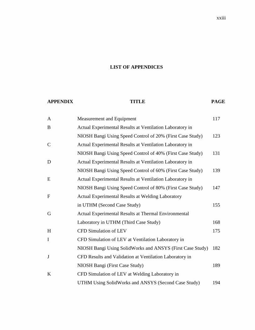
xxiii
LIST OF APPENDICES
APPENDIX TITLE PAGE
A Measurement and Equipment 117
B Actual Experimental Results at Ventilation Laboratory in
NIOSH Bangi Using Speed Control of 20% (First Case Study) 123
C Actual Experimental Results at Ventilation Laboratory in
NIOSH Bangi Using Speed Control of 40% (First Case Study) 131
D Actual Experimental Results at Ventilation Laboratory in
NIOSH Bangi Using Speed Control of 60% (First Case Study) 139
E Actual Experimental Results at Ventilation Laboratory in
NIOSH Bangi Using Speed Control of 80% (First Case Study) 147
F Actual Experimental Results at Welding Laboratory
in UTHM (Second Case Study) 155
G Actual Experimental Results at Thermal Environmental
Laboratory in UTHM (Third Case Study) 168
H CFD Simulation of LEV 175
I CFD Simulation of LEV at Ventilation Laboratory in
NIOSH Bangi Using SolidWorks and ANSYS (First Case Study) 182
J CFD Results and Validation at Ventilation Laboratory in
NIOSH Bangi (First Case Study) 189
K CFD Simulation of LEV at Welding Laboratory in
UTHM Using SolidWorks and ANSYS (Second Case Study) 194

xxiv
L CFD Results and Validation at Welding Laboratory in UTHM
(Second Case Study) 198
M CFD Simulation of LEV at Thermal Environmental
Laboratory in UTHM Using SolidWorks and ANSYS
(Third Case Study) 200
N CFD Results and Validation at Thermal Environmental
Laboratory in UTHM (Third Case Study) 204
O CFD Simulation of LEV at Welding Laboratory in UTHM
with Different Types of Contaminant Sources Using ANSYS 206
P Calculation to Determine LEV System is Turbulent 211
Q Calculation to Determine Fluid Flow is Incompressible 215
CHAPTER 1
INTRODUCTION
Contaminants such as dusts, mists, gases, vapour, fumes and so forth are the most
common organic in which humans are exposed due to extensive use at workstations.
Each year, at least thousands of workers are infected with occupational asthma and other
lung diseases (Health and Safety Executive, 2010). Studies have found that exposure to
such contaminants mentioned above can cause health effects (Flynn et al., 2003).
Although some machines may come with a dust or fume handling device attached
together, it is often necessary to meet exposure level requirements.
An efficient and capable method to this problem is the installation of local
exhaust ventilation (LEV). LEV captures airborne contaminants close to the source of
emission. It is generally achieved by using hood, duct, air cleaner, fan and discharge
which remove contaminants before they have a chance to escape in workstations. LEV is
used in order to help reducing workers’ exposure to contaminants at workstations. The
use of LEV resulted in an overall exposure reduction of 92% (Croteau et al., 2004).
However, the reduction is highly depending on the way it is installed and used by
workers (Wurzelbacher et al., 2010). The design and usage of LEV are often
underappreciated (Shepherd et al., 2008). More attention should be paid to proper use
and maintenance of LEV in various sectors (Meijster et al., 2007).
In order to take advantage of LEV design to ensure higher efficiency and
performance of LEV, computational fluid dynamics (CFD) can be used and performed.

2
CFD is a design tool used to describe and simulate fluid dynamic phenomena.
Simulation is used to forecast or reconstruct the behavior of an engineering product or
physical situation under assumed or measured boundary conditions. Moreover, CFD can
provide information of airflow distribution and air quality within a room. CFD have
been increasingly used to calculate airflow velocities and temperatures in indoor
environment such as food court center (Wong et al., 2006), home appliances (Lim et al.,
2008), stadium (Stamou et al., 2008), hospital room (Mendez et al., 2008), and aircraft
cabin (Yan et al., 2009). Despite the extensive usage of CFD application in various
indoor environments, there are only a few past studies involving LEV.
1.1 Background of Problem
LEV is often used in industries and training facilities building where trainings on the
work tasks are provided to occupants. Examples of places where application of LEV is
used are Ventilation Laboratory in National Institute for Occupational Safety and Health
(NIOSH) Bangi, Welding Laboratory and Thermal Environmental Laboratory in
Universiti Tun Hussein Onn. Case studies were performed at these three places to
perform actual experiments and CFD simulations.
The usage of LEV significantly reduced exposure of fiber particles with LEV
than with no LEV (Mazzuckelli et al., 2004). Although the reduction showed good
indication of LEV usage, however, Mazzuckelli et al. suggested that proper design of
LEV is the main vital point to LEV effectiveness. Another similar study showed that
application of LEV decreased total particulate concentrations by 75% (Wurzelbacher et
al., 2010). In a food flavourings production facility, an average concentration reduction
by up to 96% was obtained after LEV system was installed (Khanzadeh et al., 2007).
Based on Khanzadeh et al. result, it demonstrated that basic exhaust hood design can
help reducing occupants’ exposure during the mixture of flavouring chemicals. Another
researcher stated that effectiveness of LEV was effective at reducing welder’s exposure
during welding tasks if proper design and usage of exhaust hood was implemented

3
(Meeker et al, 2010). In another related study performed by (Cena et al., 2011), LEV
design and condition contributed to the effectiveness to capture airborne particles by
sanding carbon nanotubes (CNT).
Although there are studies on application of LEV by comparing with and without
usage of LEV system to determine effectiveness in protecting occupants’ exposure to
contaminants (Mazzuckelli et al., 2004, Khanzadeh et al., 2007, Meeker et al, 2010,
Cena et al., 2011), however, there is only one study involving LEV design simulation
using CFD methods (Inthavong et al., 2009). Furthermore, almost all of the CFD
simulation in past studies involves mechanical ventilation system, e.g. ceiling fan, wall
fan, exhaust fan, etc. Nevertheless, the techniques, turbulence model and boundary
conditions performed by past researchers can be used as a guide in this study. Based on
literature studies involving CFD methods, a 3D numerical analysis method was
performed to investigate which kitchen hood system was suitable by comparing CFD
analysis results (Lim et al., 2008). Another study performed at a hawker center in
Singapore, CFD techniques were carried out to determine and predict which ventilation
system was suitable to be used (Wong et al., 2006). Based on Wong et al. result,
installing exhaust fans could improve air temperature performance most effectively. A
hospital room using CFD methodology was also performed to optimize ventilation flow
pattern (Mendez et al., 2008). It showed that CFD simulation of a partition wall with a
small gap near ceiling achieved the most favorable ventilation flow pattern. Another
investigation of effectiveness of ventilation design in a woodturning workstation was
modeled and simulated using CFD approach (Inthavong et al., 2009). Five different
ventilation designs were considered and modeled to evaluate airflow patterns and wood
dust removal from the woodturning station. It was found that ventilation with local and
angled outlet of 45° emanated from roof provided greatest total particle clearance and
low particles in breathing plane.

4
1.2 Objective of Study
The main objectives in this study are as follows:
a) To validate CFD simulation results with actual experimental results.
b) To identify effectiveness of LEV systems using actual experimental results.
1.3 Problem Statement of Study
This study is aimed to find answers to several questions related. First, to identify
effectiveness of LEV systems, what airflow parameter should be measured? Second,
what is the correct method and procedure to obtain and measure airflow parameter in
LEV hood and duct? Third, which LEV systems in three case studies achieve all
recommended minimum hood velocity and recommended velocity along ducts as stated
in Guidelines on Occupational Safety and Health for Design, Inspection, Testing and
Examination of LEV system by Department of Safety and Health (DOSH)? Fourth,
before CFD simulation is carried out, what are the simulation parameters (boundary
conditions) that should be determined? Fifth, which is the most suitable CFD turbulence
model should be used in LEV’s compartment simulation? Sixth, can CFD tool capable
to give accurate predictions or low percentage of errors compare with actual
experimental results in terms of airflow parameter?
5
1.4 Scope of Study
The scopes of this study are mainly focused on airflow distribution and characteristics in
LEV’s compartment. Project scopes are as follows:
a) Three case studies were conducted at Ventilation Laboratory in National Institute
for Occupational Safety and Health (NIOSH) Bangi, Selangor; Welding
Laboratory and Thermal Environmental Laboratory at Universiti Tun Hussein
Onn Malaysia, Johor.
b) Actual experiment methods were performed by referring to Guidelines on
Occupational Safety and Health for Design, Inspection, Testing and Examination
of LEV system by DOSH.
c) Measurement of velocity pressure (VP) and static pressure (SP) were measured
and obtained from actual experiments.
d) Simulations of airflow distribution in LEV were performed using CFD tool.
e) Contaminants such as dusts, gases, fume and so forth were not taken into
consideration in this study as equipment used (GrayWolf IQ-410 Indoor Air
Quality Probe) were defective.
f) Heat sources surrounding the LEV, such as fluorescent lamp, light bulb and so
forth were considered to have small effects and thus were neglected in this study.
As stated in Guidelines on Occupational Safety and Health for Design,
Inspection, Testing and Examination of LEV system by DOSH, measurement of
hood velocity and velocity pressure (VP) along ducts were obtained to identify
LEV system effectiveness.
g) No occupants were involved throughout all three case studies as this study was
not a comparison between LEV system on and LEV system off by measuring
personal breathing zone (PBZ).

6
1.5 Significance of Study
This study is important because:
a) It is conducted to measure and simulate a proper study related with engineering
control equipment in workstations to control exposure reduction.
b) Effectiveness of LEV system can be identified through experimental
measurements using anemometer and pitot tube to obtain hood velocity, velocity
pressure (VP) and static pressure (SP) as stated in Guidelines on Occupational
Safety and Health for Design, Inspection, Testing and Examination of LEV
system by DOSH.
c) A better prediction of airflow parameter via the use of proper CFD model greatly
reduces cost and time involved as compared to actual experimental methods.
d) After simulations are validated with actual experimental results, techniques of
simulation, e.g. the correct and right turbulence model, boundary conditions, etc.
are known. From here, it can be a guideline or benchmark so that future LEV
design simulation can be drawn and simulated accurately.

CHAPTER 2
THEORY AND LITERATURE REVIEW
2.1 Local Exhaust Ventilation (LEV)
LEV is a system that uses extract ventilation to capture contaminants from being
breathed by humans in workstations. The main elements of LEV system are hood, duct,
fan and discharge. Figure 2.1 shows the common elements of LEV system.
Figure 2.1: Common elements of LEV system (Guidelines on Occupational Safety and
Health for Design, Inspection, Testing and Examination of LEV system, 2008)

8
2.1.1 Hood
Hood is used to capture contaminants generated in air stream directed towards the hood.
The hood is the most important and critical element of LEV system because
effectiveness of LEV depends on whether enough contaminants are retained or captured
by the hood to ensure contaminants in workstations is below the acceptable limit. The
recommended minimum hood velocity is 100 ft/min, based on Guidelines on
Occupational Safety and Health for Design, Inspection, Testing and Examination of
LEV system by DOSH. There are two types of hoods, which are enclosure hood and
exterior hood. Enclosure hood is a hood that completely or partially encloses
contaminant course, while exterior hood is located adjacent to contaminant source
without enclosing it. Figure 2.2 and Figure 2.3 show examples of enclosure hood and
exterior hood. The type of hood to be used depends on the physical characteristics of
process equipment, contaminant generation mechanism and operator or equipment
interface.
Figure 2.2: An example of enclosure hood (Guidelines on Occupational Safety and
Health for Design, Inspection, Testing and Examination of LEV system, 2008)

9
Figure 2.3: Example of exterior hoods (Guidelines on Occupational Safety and Health
for Design, Inspection, Testing and Examination of LEV system, 2008)

10
2.1.2 Duct
Duct is a network of ducting system that connects the hood and other elements of LEV
system. Duct transports contaminants and discharges to the atmosphere through
discharge. The most important and critical consideration in ducting system design is to
reduce losses of energy that will affect contaminated airflow in the duct. Reduction of
flow losses will cause dust to settle in the duct and resulting in clogging problem and
this will reduce hood suction rate. Therefore, velocity along ducts must be sufficient
enough to transport contaminants out of workstations. According to Guidelines on
Occupational Safety and Health for Design, Inspection, Testing and Examination of
LEV system by DOSH, the recommended velocity along ducts for vapours, gases and
smoke is 1000 ft/min, while 2000 ft/min is required for welding. Figure 2.4 shows an
example of ducts at Welding Laboratory in UTHM.
Figure 2.4: An example of ducts at Welding Laboratory in UTHM

11
2.1.3 Fan
Fan provides energy to suck contaminants into hood by inducing pressure of suction in
the duct. Fan converts electrical power into suction pressure and increases air velocity.
Selections of fan include types of contaminants transported in LEV system, total air flow
rate required by LEV system, and size of location where fan is placed. Figure 2.5 shows
examples of fan used in LEV system.
Figure 2.5: Examples of fan used in LEV system (Guidelines on Occupational Safety
and Health for Design, Inspection, Testing and Examination of LEV system, 2008)
12
2.2 Application of LEV System
In this study, application of LEV system are reviewed from past researchers’ literature.
The past researchers’ literature can be used as a guide in this study.
2.2.1 Engineering Control of Disc Sander in a Plant
National Institute for Occupational Safety and Health (NIOSH) Ohio, United States
conducted an engineering control evaluation of a company that produced vacuum-
formed ceramic fiber parts. The request was made by the company itself to examine the
efficacy of a LEV system they had developed to capture and collect airborne refractory
ceramic fibers (RCFs) during sanding of vacuum-formed parts (Mazzuckelli et al.,
2004).
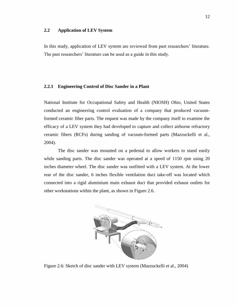
The disc sander was mounted on a pedestal to allow workers to stand easily
while sanding parts. The disc sander was operated at a speed of 1150 rpm using 20
inches diameter wheel. The disc sander was outfitted with a LEV system. At the lower
rear of the disc sander, 6 inches flexible ventilation duct take-off was located which
connected into a rigid aluminium main exhaust duct that provided exhaust outlets for
other workstations within the plant, as shown in Figure 2.6.
Figure 2.6: Sketch of disc sander with LEV system (Mazzuckelli et al., 2004)

13
Evaluation was conducted with the LEV system on (control-on) and with the
system off (control-off). In order to minimize the effect of cross contamination between
runs, the control-on trials were done before the control-off trials. The same exact
operator was used in each trial to minimize the effect of human variation.
Results showed that with the control off trials, the personal breathing zone (PBZ)
average concentration obtained was 44 fibers/cubic centimeter (f/cc) and with the
control on trials, the PBZ average concentration obtained was 0.35 fibers/cubic
centimeter (f/cc).
2.2.2 Engineering Control in Welding Industry
There are currently two methods to ventilate weld fume exposure for welding task in a
closed space: dilution ventilation (DV) or LEV (Wurzelbacher et al., 2010). DV involves
producing fresh air to flow into a closed space at very high velocity. Under certain
circumstances, this air flow created by DV will produce a mixing or turbulence that
forces any contaminated air out of any available openings in the space. This method is
very useful when it is applied to a closed space that has only one single opening because
DV does not depend on directional flow to draw contaminants away from workers.
However, DV with arising turbulence can be very incompetent and ineffective in
discharging contaminants from welders’ PBZ. On the other hand, LEV system uses a fan
with a decent capture velocity to discharge contaminated air through the fan and ducting
and out of closed space. Wurzelbacher et al. conducted an evaluation to determine the
effectiveness of DV and LEV in welding area.
Wurzelbacher et al. performed this study on three welders as they conducted
their typical work shift in the shipyard. Each welder wore the appropriate personal
protective equipment as stated by the shipyard’s rules and regulations such as welding
helmet, insulated overalls, gloves, ultraviolet (UV) protective face shield and personal
respirator which included disposable welding mask with a particulate filter. For safety
precaution sake, all welding tasks were executed in accordance with safe welding
14
guidelines as recommended by the American Welding Society (AWS). Wurzelbacher et
al. also videotaped welders’ movements to monitor the relationships between welder
posture or position, welding fume exposure and ventilation method usage.
Results showed that LEV method reduced total particulate concentrations (mg /
m3) by 75% over the DV method. This result could be supported by the fact that air flow
rates achieved through the closed space were up to five times greater with the LEV than
with the DV method. The effectiveness of both LEV and DV were also greatly
contributed by individual work practices of the welders. DV is less effective because it
does not remove fume efficiently from welders’ PBZ due to welders’ positioning effects.
Worker’s position (in reference to the air flow direction) and posture (in regard to the
weld fume plume) significantly affect weld fume exposure. However, in closed spaces,
optimal positioning of the workers with respect to ventilation flows is often not possible.
In another similar welding tasks study performed by another researcher (Wallace
et al., 2002), data collected during seven sample runs showed that LEV helped to reduce
weld fume exposures. The total welding fume exposures for the personal and area
samples with the ventilation on were five times lower than with it off. When welders’
were welding outside, windy air plays a major and significant role in how much weld
fume would be transferred into workers’ breathing zone. Besides that, the usage of LEV
may not significantly reduce workers’ exposure when welding outside due to the strong
effect of wind currents.

15
2.2.3 Engineering Control of Exhaust Hoods of LEV System
In November 2006, NIOSH Ohio, United States researchers conducted an evaluation in
a food flavourings production facility (Old et al., 2008). The company was a wholesale
flavour and colour manufacturer that produces more than 1500 flavours in liquid,
powder, natural and artificial forms. The company consisted of both stationary and
mobile open tanks for mixing liquid flavouring ingredients. Small quantities of
flavouring ingredients were poured and mixed by employees on top of a bench and then
large pours were completed directly into the mixing tank.
In May 2007, a new LEV system was installed in the liquid production room.
The newly developed LEV consisted of two main types of LEV hoods. The first hood
was a ventilated bench top, back draft, slotted hood where it was used to control
workers’ exposure to chemicals during pouring activities where a majority of the
workday was involved. A total of five such LEV systems were installed in the liquid
compounding room.
On the other hand, the second hood was similar to a booth that allowed
containment of large mobile mixing tanks where it was used to collect chemical vapours
while the worker poured flavouring ingredients into large mixers. A total of three such
hoods were installed in the liquid flavouring compounding room. The first and second
hoods mentioned are shown in Figure 2.7 and Figure 2.8.

16
Figure 2.7: Small mixing ventilated exhaust hood (Old et al., 2008)
Figure 2.8: Large mixing ventilated booth-type exhaust hood (Old et al., 2008)

17
Evaluation was conducted quantitatively by using tracer gas to determine the
capture efficiency of each hood. Tracer gas was released at a constant rate where
contaminant control was desired. Then, the corresponding downstream of tracer gas
concentration was measured inside exhaust duct. The tracer gas used was a mixture of
10% sulfur hexafluoride in air. The tracer gas concentration was measured using a
MIRAN 205B Sapphire portable ambient air analyzer. The setup of tracer gas capture
test is shown in Figure 2.9.
Figure 2.9: Tracer gas capture test setup (Old et al., 2008)
The quantitative collection efficiencies for each hood are shown in Table 2.1.
The capture efficiencies ranged from 89% - 100% for all hoods. Several tests were
performed at Hood 1 because it was believed that Hood 1 was likely to be affected by
cross drafts than other hoods due to its closeness to the room opening.

18
Table 2.1: Quantitative collection efficiencies for each hood (Old et al., 2008)
Hood No. (Type) Capture Efficiency (%)
Hood 1 (Bench Top) 89-97
Hood 2 (Bench Top) 98
Hood 3 (Bench Top) 100
Hood 5 (Bench Top) 98
Hood 6 (Booth Type) 97
Hood 7 (Booth Type) 96
Hood 8 (Booth Type) 98
Hood 9 (Bench Top) 98-99
A more detailed efficiency evaluation test was conducted by activating control
on and control off of selected hoods. Three separate control on / control off tests were
conducted to evaluate effectiveness of LEV system. Results are shown in Figure 2.10.
When LEV system was activated, the average concentration was reduced by 96%, 93%
and 90% in Tests 1,2 and 3 respectively.

19
Figure 2.10: Real-time evaluation of bench top exhaust hoods – control on / control off
(Old et al., 2008)
20
Based on the results, it demonstrated that exhaust hoods on existing designs can
greatly reduce workers’ exposure during the use and mixing of flavouring chemicals. By
using these exhaust hoods of LEV system, other operations such as packaging of powder
flavourings and pouring of diacteyl and other high priority chemicals can be more safely
performed. However, workers must be trained on proper use of LEV system and new
operational safeguards must be implemented in order to get the best efficiency of LEV
system. Critical and necessary training such as verifying fan operation status and making
sure worker knows how to always position contaminant source between him and the
exhaust hood are vital and important.
In another similar study performed by other researcher (Meeker et al, 2010), an
assessment on effectiveness of LEV during welding tasks was conducted. In the study,
Meeker et al. stated that the use of LEV was effective at reducing welders’ exposure and
should be incorporated into welding tasks on a routine basis. To take good advantage of
LEV system, Meeker et al. found out that effectiveness of LEV was related to proper
usage of exhaust hood. If the hood was placed below or too far away from the weld
fume, the LEV’s effectiveness could be greatly compromised. It was noted that LEV
hoods were placed up to 2 feet (61 cm) away from the weld, therefore, welders should
be taught or trained for proper usage and handling and basic guiding principles as well to
maximize weld fume collection.
A three LEV tests (no LEV, custom fume hood and biosafety cabinet) conducted
by (Cena et al., 2011) to evaluate the effectiveness of LEV hoods to capture airborne
particles by sanding CNT nanocomposites. Results showed that release of airborne
nanoparticles within a hood into the laboratory environment is highly dependent on hood
design and hood condition such as height of hood being used, face velocity and so forth.
In the study, Cena et al. also found out that a biological safety cabinet was more
effective than a custom fume hood of LEV. Cena et al. pointed that the poor
performance of the custom fume hood of LEV might be due to its lack of a front sash, its
lack of rear baffles to distribute air flow and its low face velocity.
LEV, described by (Smandych et al., 1998), is much more cost efficient than
with general building ventilation. Smandych et al. also stressed that the most important
component of a LEV system is the hood. In order to obtain the optimal and maximum

21
dust control, the type, size and location of LEV hood are critical and important. The
shape of LEV hood affects dust plume containment, pressure losses and required air
flow rate, while the location of LEV hoods affects maximum dust capture efficiency at
minimum exhaust volumes.
Hood design for portable hand-held hammer drills, suggested by (Shepherd et al.,
2008), needs to be examined for both technical and practical reasons. The practical issue
of fitting LEV hood onto all different hammer frills currently being used must be a
priority to gain acceptance in the field. In another study, (Ojima et al., 2007) stated that
the effectiveness of LEV hood was not sufficient enough and workers’ exposure could
not be prevented completely by LEV alone.
2.2.4 Engineering Control of Wet Grinding, Ventilated Grinding and
Uncontrolled Conventional Grinding in Construction Industry
A study was conducted to evaluate effectiveness of respirable silica dust and respirable
suspended particulate matter reduction using grinders equipped with a continuous water
flow system (wet grinder) and also grinders equipped with LEV system (LEV grinder),
and after that the results would then be compared with those grinders with no local dust
reduction accessories (uncontrolled conventional grinders) (Khanzadeh et al., 2007).
Workers dealing with concrete products in certain construction areas have the potential
to unacceptable exposure of crystalline silica dust levels. Extreme inhalation of this
dangerous dust exposure has been associated to a lot of diseases such as silicosis, lung
cancer, rheumatoid arthritis, scleroderma, Sjogern’s syndrome, lupus, renal and so forth.
Concrete grinding activities were conducted in a laboratory of approximately 7.2
meter x 4.8 meter x 4.8 meter, which was located at the back of a general industrial
building. A general ventilation system was installed in the field laboratory and could
exhaust air to the outside. The general ventilation system had a volumetric suction flow
rate of 40 room air exchanges per hour when activated. In the field laboratory, concrete
surface grinding was performed between operator and general ventilation inlet.

22
Uncontrolled conventional grinding was performed using 11.4 cm and 17.5 cm
size grinders. Wet grinding was performed using 17.5 cm size grinder with a water hose
attached to the grinder, and the water flow was set by concrete grinding operator at 3
L/min. The reason 3 L/min water flow was used is because it was the critical water flow
rate for this type of grinder, while keeping concrete surface wet during grinding and
preventing water splash. LEV grinding was performed using a ventilated 15 cm size
grinder. The LEV consisted of a dry type vacuum cleaner with a hose attaching the
vacuum to the grinder. The LEV capacity used on the grinder was 50 L/s. Figure 2.11,
Figure 2.12 and Figure 2.13 show uncontrolled conventional grinder, wet grinder and
LEV grinder, respectively.
Figure 2.11: A 17.5 cm size uncontrolled conventional grinder (Khanzadeh et al., 2007)

23
Figure 2.12: A 17.5 cm size wet grinder with water hose attached (Khanzadeh et al.,
2007)
Figure 2.13: A 15 cm LEV grinder with vacuum system (Khanzadeh et al., 2007)
24
Results showed that wet grinding was effective in geometric mean
concentrations of respirable silica dust with a reduction of 98.2%. LEV grinding was
even more effective with geometric mean concentrations of respirable silica dust with a
reduction of 99.7%. Besides that, further detailed tests showed that wet grinding was
effective in geometric mean concentrations of respirable suspended particulate matter
with a reduction of 97.6%. LEV grinding was even more effective with geometric mean
concentrations of respirable suspended particulate matter with a reduction of 99.6%.
The results of this study represent that the application of LEV grinding or wet
grinding methods will reduce levels of respirable silica dust dramatically. However,
Khanzadeh et al. suggested that workers should be educated and trained first on
effectiveness and correct applications and usage of dust reduction accessories for
concrete grinding. An appropriate respirator may also be needed to further reduce silica
dust inhalation during concrete surface grinding.
In another similar research which was done by (Croteau et al., 2004), the
application of LEV resulted in a mean exposure reduction of 92%. Croteau et al. found
out that for many construction activities, LEV appeared to be the most effective way to
reduce silica dust exposures and that the replacement of products with lower crystalline
silica content might be possible for limited and special conditions, but it is not readily
and applicable especially in many construction materials. Croteau et al. also suggested
that water spray or wet grinder method could effectively reduce exposure levels but it is
not suitable in many applications because water could result in material discoloration
and expansion, building damage and waste water disposal problems. Despite the high
percentage reduction when using LEV system, however, Croteau et al. recommended
that workers should use respiratory protection with a protection factor of between 5 and
10 when they use hand-held grinders. When LEV system is not used, workers should use
a respirator that has a protection factor greater than 10.
In a later research, (Khanzadeh et al., 2010) found out that although current
engineering control could be the most promising method, however, it still could not
reduce silica dust to below the American Conference of Industrial Hygienists (ACGIH)
recommended silica dust exposure criteria of 0.025 mg / m3. Therefore, Khanzadeh et al.
recommended that until a very appropriate higher efficiency dust control methods are

112
REFERENCES
American Conference of Governmental Industrial Hygienists (ACGIH), 2007. Industrial
Ventilation. A Manual of Recommended Practice for Operation and
Maintenance.
Carlo, R.V., Sheehy, J., Feng, H.A., Sieber, W.K., 2010. Laboratory Evaluation to
Reduce Respirable Crystalline Silica Dust When Cutting Concrete Roofing Tiles
Using a Masonry Saw. Journal of Occupational and Environmental Hygiene
Volume 7:4, page 245 – 251.
CD-adapco STAR-CCM+ 2009.
STAR-CCM+ Tutorial Guide.
Cena, L.G., Peters, T.M., 2011. Characterization and Control of Airborne Particles
Emitted During Production of Epoxy/Carbon Nanotube Nanocomposites. Journal
of Occupational and Environmental Hygiene Volume 8:2, page 86 – 92.
CFD Online Discussion Forums.
http://www.cfd-online.com/Forums/
Croteau, G.A., Flanagan, M.E., Camp, J.E., Seixas, N.S., 2004. The Efficacy of Local
Exhaust Ventilation for Controlling Dust Exposures During Concrete Surface
Grinding. Annals of Occupational Hygiene Journal Volume 48, page 509 – 518.

113
Department of Occupational Safety and Health (DOSH), 2008. Guidelines on
Occupational Safety and Health for Design, Inspection, Testing and Examination
of Local Exhaust Ventilation System.
Flynn M.R., Susi, P., 2003. A Review of Engineering Controls for Selected Silica and
Dust Exposures in the Construction Industry. Applied Occupational and
Environmental Hygiene Journal Volume 18:4, page 268 – 277.
Health and Safety Executive, 2010. Working with Substances Hazardous to Health. A
Brief Guide to Control of Substances Hazardous to Health (COSHH)
Regulations.
Inthavong, K., Tian, Z.F., Tu, J.Y., 2009. Effect of Ventilation Design on Removal of
Particles in Woodturning Workstations. Building and Environment Journal
Volume 44, page 125 – 136.
Kaviany, M., 2002. Principles of Heat Transfer. Wiley-Interscience Publication. John
Wiley & Sons, Inc., New York.
Khanzadeh, F.A., Milz, S., Ames, A., Susi, P.P., Bisesi, M., Khuder, S.A., Khanzadeh,
M.A., 2007. Crystalline Silica Dust and Respirable Particulate Matter During
Indoor Concrete Grinding - Wet Grinding and Ventilated Grinding Compared
with Uncontrolled Conventional Grinding. Journal of Occupational and
Environmental Hygiene Volume 4, page 770 – 779.
Khanzadeh, F.A., Milz, S.A., Wagner, C.D., Bisesi, M.S., Ames, A.L., Khuder, S., Susi,
P., Khanzadeh, M.A., 2010. Effectiveness of Dust Control Methods for
Crystalline Silica and Respirable Suspended Particulate Matter Exposure During
Manual Concrete Surface Grinding. Journal of Occupational and Environmental
Hygiene Volume 7:12, page 700 – 711.
114
Kulmala, I.K., 1997. Air Flow Field Near a Welding Exhaust Hood. Applied
Occupational and Environmental Hygiene Journal Volume 12:2, page 101 – 104.
Lim, K., Lee, C., 2008. A Numerical Study on The Characteristics of Flow Field,
Temperature and Concentration Distribution According to Changing the Shape
of Separation Plate of Kitchen Hood System. Energy and Buildings Journal
Volume 40, page 175 – 184.
Mazzuckelli, L., Dunn, K.H., Shulman, S.A., Cecala, A.B., Venturin, D.E., 2004.
Evaluation of a Local Exhaust Ventilation System for Controlling Refractory
Ceramic Fibers During Disc Sanding. Journal of Occupational and
Environmental Hygiene Volume 1:10, page D107 – D111.
Meeker, J.D., Susi, P., Flynn, M.R., 2010. Hexavalent Chromium (CrVI) Exposure and
Control in Welding Tasks. Journal of Occupational and Environmental Hygiene
Volume 7:11, page 607 – 615.
Meijster, T., Tielemans, E., Pater, N., Heederik, D., 2007. Modeling Exposure in Flour
Processing Sectors in The Netherlands: a Baseline Measurement in the Context
of an Intervention Program. Annals of Occupational Hygiene Journal Volume
51, page 293 – 304.
Mendez, C., San Jose, J.F., Villafruela, J.M., Castro, F., 2008. Optimization of a
Hospital Room By Means of CFD For More Efficient Ventilation. Energy and
Buildings Journal Volume 40, page 849 – 854.

115
Norton, T., Sun, D.W., Grant, J., Fallon, R., Dodd, V., 2007. Applications of
Computational Fluid Dynamics (CFD) in The Modelling and Design of
Ventilation Systems in The Agricultural Industry: A Review. Bioresource
Technology Journal Volume 98, page 2386 – 2414.
Ojima, J., 2007. Efficiency of a Tool-mounted Local Exhaust Ventilation System for
Controlling Dust Exposure During Metal Grinding Operations. Journal of
Occupational Health & Safety Volume 45, page 817 – 819.
Old, L., Dunn, K.H., Garcia, A., Echt, A., 2008. Evaluation of a Local Exhaust
Ventilation System for Controlling Exposures During Liquid Flavoring
Production. Journal of Occupational and Environmental Hygiene Volume 5:11,
page D103 – D110.
Shepherd, S., Woskie, S.R., Holcroft. C., Ellenbecker M., 2008. Reducing Silica and
Dust Exposures in Construction During Use of Powered Concrete-Cutting Hand
Tools: Efficacy of Local Exhaust Ventilation on Hammer Drills. Journal of
Occupational and Environmental Hygiene Volume 6:1, page 42 – 51.
Smandych, R.S., Thomson, M., Goodfellow, H., 1998. Dust Control for Material
Handling Operations: A Systematic Approach. American Industrial Hygiene
Association Journal Volume 59:2, page 139 – 146.
Versteeg, H.K., Malalasekera, W., 2007. An Introduction to Computational Fluid
Dynamics: The Finite Volume Method (2nd
Edition). Prentice Hall.
Wallace, M., Fischbach, T., 2002. Effectiveness of Local Exhaust for Reducing Welding
Fume Exposure During Boiler Rehabilitation. Applied Occupational and
Environmental Hygiene Journal Volume 17:3, page 145 – 151.
116
Wong, N.H., Song, J., Istiadji, A.D., 2006. A study of the effectiveness of mechanical
ventilation systems of a hawker center in Singapore using CFD simulations.
Building and Environment Journal Volume 41, page 726 – 733.
Wurzelbacher, S.J., Hudock, S.D., Johnston, O.E., Blade, L.M., Shulman, S.A., 2010. A
Pilot Study on the Effects of Two Ventilation Methods on Weld Fume Exposures
in a Shipyard Confined Space Welding Task. Applied Occupational and
Environmental Hygiene Journal Volume 17:11, page 735 – 740.