a study of the long-term applications of … study of the long-term applications of vinyl sheet...
TRANSCRIPT
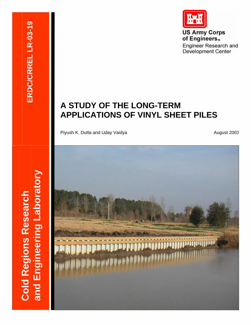
A STUDY OF THE LONG-TERM APPLICATIONS OF VINYL SHEET PILES
ERD
C/C
RR
EL L
R-0
3-19
Piyush K. Dutta and Uday Vaidya August 2003
Col
d R
egio
ns R
esea
rch
and
Engi
neer
ing
Labo
rato
ry
Report Documentation Page Form ApprovedOMB No. 0704-0188
Public reporting burden for the collection of information is estimated to average 1 hour per response, including the time for reviewing instructions, searching existing data sources, gathering andmaintaining the data needed, and completing and reviewing the collection of information. Send comments regarding this burden estimate or any other aspect of this collection of information,including suggestions for reducing this burden, to Washington Headquarters Services, Directorate for Information Operations and Reports, 1215 Jefferson Davis Highway, Suite 1204, ArlingtonVA 22202-4302. Respondents should be aware that notwithstanding any other provision of law, no person shall be subject to a penalty for failing to comply with a collection of information if itdoes not display a currently valid OMB control number.
1. REPORT DATE AUG 2003 2. REPORT TYPE
3. DATES COVERED -
4. TITLE AND SUBTITLE A Study of the Long-Term Applications of Vinyl Sheet Piles
5a. CONTRACT NUMBER
5b. GRANT NUMBER
5c. PROGRAM ELEMENT NUMBER
6. AUTHOR(S) 5d. PROJECT NUMBER
5e. TASK NUMBER
5f. WORK UNIT NUMBER
7. PERFORMING ORGANIZATION NAME(S) AND ADDRESS(ES) Cold Regions Research and Engineering Laboratory,72 Lyme Road,Hanover,NH,03755
8. PERFORMING ORGANIZATIONREPORT NUMBER
9. SPONSORING/MONITORING AGENCY NAME(S) AND ADDRESS(ES) 10. SPONSOR/MONITOR’S ACRONYM(S)
11. SPONSOR/MONITOR’S REPORT NUMBER(S)
12. DISTRIBUTION/AVAILABILITY STATEMENT Approved for public release; distribution unlimited
13. SUPPLEMENTARY NOTES The original document contains color images.
14. ABSTRACT see report
15. SUBJECT TERMS
16. SECURITY CLASSIFICATION OF: 17. LIMITATION OF ABSTRACT
18. NUMBEROF PAGES
91
19a. NAME OFRESPONSIBLE PERSON
a. REPORT unclassified
b. ABSTRACT unclassified
c. THIS PAGE unclassified
Standard Form 298 (Rev. 8-98) Prescribed by ANSI Std Z39-18

A STUDY OF THE LONG-TERM APPLICATIONS OF VINYL SHEET PILES
Piyush K. Dutta
U.S. Army Corps of Engineers
Engineer Research and Development Center
Cold Regions Research and Engineering Laboratory
Hanover, NH 03755
Uday Vaidya
Department of Materials Science
University of Alabama at Birmingham
Birmingham, AL 35294

ii
iii
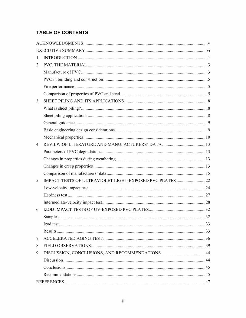
TABLE OF CONTENTS
ACKNOWLEDGMENTS................................................................................................................v EXECUTIVE SUMMARY.............................................................................................................vi 1 INTRODUCTION .....................................................................................................................1 2 PVC, THE MATERIAL ............................................................................................................3
Manufacture of PVC..................................................................................................................3 PVC in building and construction..............................................................................................5 Fire performance........................................................................................................................5 Comparison of properties of PVC and steel...............................................................................5
3 SHEET PILING AND ITS APPLICATIONS...........................................................................8 What is sheet piling?..................................................................................................................8 Sheet piling applications ............................................................................................................8 General guidance .......................................................................................................................9 Basic engineering design considerations ...................................................................................9 Mechanical properties..............................................................................................................10
4 REVIEW OF LITERATURE AND MANUFACTURERS’ DATA.......................................13 Parameters of PVC degradation...............................................................................................13 Changes in properties during weathering.................................................................................13 Changes in creep properties .....................................................................................................13 Comparison of manufacturers’ data.........................................................................................15
5 IMPACT TESTS OF ULTRAVIOLET LIGHT-EXPOSED PVC PLATES ..........................22 Low-velocity impact test..........................................................................................................24 Hardness test ............................................................................................................................27 Intermediate-velocity impact test.............................................................................................28
6 IZOD IMPACT TESTS OF UV-EXPOSED PVC PLATES...................................................32 Samples....................................................................................................................................32 Izod test....................................................................................................................................33 Results......................................................................................................................................33
7 ACCELERATED AGING TEST ............................................................................................36 8 FIELD OBSERVATIONS.......................................................................................................39 9 DISCUSSION, CONCLUSIONS, AND RECOMMENDATIONS........................................44
Discussion................................................................................................................................44 Conclusions..............................................................................................................................45 Recommendations....................................................................................................................45
REFERENCES...............................................................................................................................47

iv
APPENDIX A: Questionnaire for the manufacturer’s data............................................................49 APPENDIX B1. Response from Materials International, Inc ........................................................51 APPENDIX B2. Response from Crane Products Ltd.....................................................................56 APPENDIX B3. Response from Northstar Vinyl Products, LLC..................................................60 APPENDIX D: Trip Report by Vic Agostinelli – Meeting on Vinyl Sheet Piling in the New
Orleans District on 27 March 2003 ...................................................................................79
v
ACKNOWLEDGMENTS
The authors gratefully acknowledge the advice and cooperation of the Consulting Task Group, which included Walter Baumy, John Bivona, Tom Wade Wright, Allen Coates, Richard Varuso, Carolyn Earl, Brett Herr, Jorge Romero, Anjana Chudgar, Victor Agostinelli, Stanley Woodson, Reed Mosher, Stacey Anastos, and Carl Guggenheimer. We owe special thanks to John Bivona and Tom Wade Wright of the New Orleans District for their input with first-hand knowledge and experience with using vinyl sheet piling. We also recognize the valuable information, insights, and perspectives given by Victor Agostinelli and Carl Guggenheimer. Walter Baumy provided continuous support and encouragement. The authors also gratefully acknowledge the support of the vinyl sheet pile manufacturers’ representatives, especially John Yeosock of Materials International, Steve Kulp of Northstar Vinyl Products, and Tony Groh of Crane Products Ltd. The support and information on vinyl sheet piling they provided through telephone conversations, by mail, and during the field investigations were extremely valuable. There are many other individuals who have helped in this task with their technical knowledge and expertise, especially Dr. Elvira Rabinovitch of the Poly-One Corporation and Louise Parker of the ERDC-CRREL. We are especially grateful to Carl Guggenheimer for his continuing support of this work.
vi
EXECUTIVE SUMMARY
This report, written for the U.S. Army Corps of Engineers, summarizes the results of a brief investigation of the long-term application of vinyl sheet piles to address some of the concerns raised in a recent Engineering and Construction Bulletin about the integrity, durability, impact damage, construction standards, and allowable design of commercially available PVC sheet piles. The data used in this investigation were available from existing literature, technical organizational databases, (e.g. the Vinyl Institute), manufacturers’ input, input from the technical experts on vinyl, and a few limited laboratory tests. The comments apply primarily to generic PVC and not to the specific PVC material of any manufacturer. The performance of an individual manufacturer’s PVC sheet pile may vary from what has been generally reported here. The following are the pertinent observations:
• Approximately ten-year-old PVC sheet pile installations have still not shown any signs of significant degradation in the material.
• Published research data from five years of weathering have shown very little degradation in tensile and flexural properties but have shown some degradation in impact properties.
• The basic material, PVC, is well investigated, and exhaustive data are available from organizations like the Vinyl Institute, Vinyl by Design, etc.
• PVC has been used in the medical, electrical, building, and construction industries for almost 50 years.
• In some places, corrosion degradation of steel pile was observed to be much faster than any degradation of PVC sheet pile.
• The four U.S. manufacturers of PVC sheet piles have different design approaches in structuring the materials and profiling the shapes of the PVC sheet piles.
• No ASTM standards or other standards were found to assess the performance of PVC sheet piles.
We performed a series of laboratory tests as below:
Accelerated aging test: Accelerated aging tests were performed on sheet pile PVC flexural samples by boiling them for 1, 2, 10, and 20 hours and comparing their flexural properties with un-boiled samples. No significant degradation in properties was observed.
UV exposure test: To study the effects of UV radiation exposure, two sets of samples were made. The first set was exposed to 350-nm, 9500-µW/in.2 UV radiation and then subjected to an ASTM 3763 tap impact test in an Instron 8250 machine. Severe discoloration was observed. No brittle cracking was observed. The depth of indentation of the tap was smallest for the highest-radiation samples. Rockwell hardness testing showed an increase in hardness of the surface with exposure.
Impact resistance degradation test: Another batch of samples similarly exposed to UV radiation were subjected to Izod impact tests. A nonlinear progressive degradation of impact strength with exposure time was observed. With a more exhaustive and systematic investigation, it would be possible to develop a model to predict the degradation rate with years.
In analyzing the overall structural performance issues of the PVC sheet piles, we observed that while material degradation generally may not be a factor in long-term performance, the
vii
selection of sheet pile design and installation must consider the impact of the low modulus of elasticity. We did not consider design issues in this short study, as it was outside the scope. But we note that because of the visco-elastic nature of the PVC, degradation of the modulus occurs over time; as a result, excessive deformation may occur over the long term under a given load without any failure. Such excessive deformation may be unacceptable, and this progressive deformation under load must be taken into consideration at the material selection and design stage. Manufacturers of PVC sheet pile must have the creep modulus degradation data available to allow appropriate selection and design. With a predictable creep modulus with time and a known load, the deformation can be calculated over the lifetime of the sheet pile. A criterion based on the maximum allowable deflection rather than the maximum allowable stress should be considered for using such visco-elastic plastic materials.
It was observed that while great savings may be obtained in many instances by replacing steel sheet piling with PVC, a solid design approach based on well-defined functional requirements is critical. Functional requirements, in addition to maintaining long-term integrity, must also include the degrees of expected resistance to various hazards, such as accidental overload, impact, fire, vandalism, etc. Functional requirements should also take into consideration the special maintenance requirements, such as frequent inspections, replacement of damaged sheets, removal of combustible materials from the vicinity, etc. Where life safety and other risks are involved, the design must address those risks. Cost-effective non-metallic FRP composite sheet piles are also commercially available, and their selection and applications must also be considered using the design and installation approach just described. On the other hand, manufacturers need to certify material specifications based on standardized testing conducted by independent test laboratories. The use of synthetic sheet piles (PVC and FRP composites) must satisfy both deflection and design criteria for failure.
A STUDY OF THE LONG-TERM APPLICATIONS
OF VINYL SHEET PILES
PIYUSH K. DUTTA AND UDAY VAIDYA
1 INTRODUCTION
Many field engineers in the U.S. Army Corps of Engineers have found that replacing heavy steel sheet piling by lightweight PVC or FRP composite sheet piling can reduce the installation cost by 30–50% per job. This is a significant saving, considering that many millions of dollars are spent by Corps Districts each year in installing new sheet piles and replacing old corroded steel sheet piles. However, concerns have been raised recently in Engineering and Construction Bulletin (ECB) No. 2002-31 (CECW-EWS 28 October 2002) about the integrity, durability, impact damage, construction standards, and allowable design of commercially available PVC sheet piles.
This report, written for the Corps of Engineers, summarizes the results of a brief investigation of the long-term application of vinyl sheet piles to address some of the concerns raised in a recent Engineering and Construction Bulletin about the integrity, durability, impact damage, construction standards, and allowable design of commercially available PVC sheet piles. The data used in this investigation were available from existing literature, technical organizational databases, (e.g. the Vinyl Institute), manufacturers’ input, input from the technical experts on vinyl, and a few limited laboratory tests. The comments apply primarily to generic PVC and not to the specific PVC material of any manufacturer. The performance of an individual manufacturer’s PVC sheet pile may vary from what has been generally reported here.
We observed that while material degradation generally may not be a factor in long-term performance, the selection of sheet pile design and installation must consider the impact of the low modulus of elasticity. We did not consider design issues in this short study, as it was outside the scope. But we note that because of the visco-elastic nature of the PVC, degradation of the modulus occurs over time; as a result, excessive deformation may occur over the long term under a given load without any failure. Such excessive deformation may be unacceptable, and this progressive deformation under load must be taken into consideration at the material selection and design stage. Manufacturers of PVC sheet pile must have the creep modulus degradation data available to allow appropriate selection and design. With a predictable creep modulus with time and a known load, the deformation can be calculated over the lifetime of the sheet pile. A criterion based on the maximum allowable deflection rather than the maximum allowable stress should be considered for using such visco-elastic plastic materials.
Section 2 of this report gives a general background of PVC as a material as used in manufacturing sheet piles. Section 3 discusses several examples of applications to prepare the

2
readers for the performance requirements for the sheet piles. Section 4 analyzes the literature data, manufacturer’s data, and the user’s experience, and Sections 5 to 7 detail the laboratory tests. Section 8 discusses the results of field observations, and Section 9 gives conclusions and some recommendations for the future.
3
2 PVC, THE MATERIAL
PVC is one of the most common, widely used, and earliest plastics developed commercially. It is formed using two natural resources, salt (57%) and oil (43%). Its use ranges from children’s toys to pipes, to window profiles, cables, and even to blood bags. It is estimated that the recent world production is of the order of 56 billion pounds/year, of which U.S. production alone accounts for 14.6 billion pounds, approximately 25%. Both national and international standards are in place in most countries to control the production, qualities, and use of PVC. There is practically very little hazard from the use of PVC. PVC has a solid history of more than 50 years of commercial use. It was first developed in 1926 by Dr. Waldo Semon of BF Goodrich (Vinyl Institute, 2003). The first commercial use was tried in shock absorber seals in the thirties, but the rapid use of PVC did not develop well until the 1950s, with the rapid growth of irrigation piping applications.
Most polymers contain carbon, hydrogen, and oxygen, all of which help combustion, and thus, in general, polymers are susceptible to fire. However, PVC contains approximately 57% chlorine by weight, which makes it flame retardant and therefore a preferred material in electrical conduits and wiring insulation. Because of its minimal toxicity it is used in food wraps. Moreover, additives used in PVC are closely regulated by the Environmental Protection Agency (EPA), the Food and Drug Administration (FDA), and the Consumer Product Safety Commission (CPSC) (Vinyl by Design, 2003).
Manufacture of PVC
Most structural engineers are familiar enough with the manufacturing and processing of steel, and they are comfortable with its properties experienced through day-to-day structural applications. Use of PVC for structural purposes may sometimes raise concerns because of the unfamiliarity of the manufacture and processing of PVC. We will briefly discuss the fundamental processes involved in PVC manufacture, and then discuss its general properties.
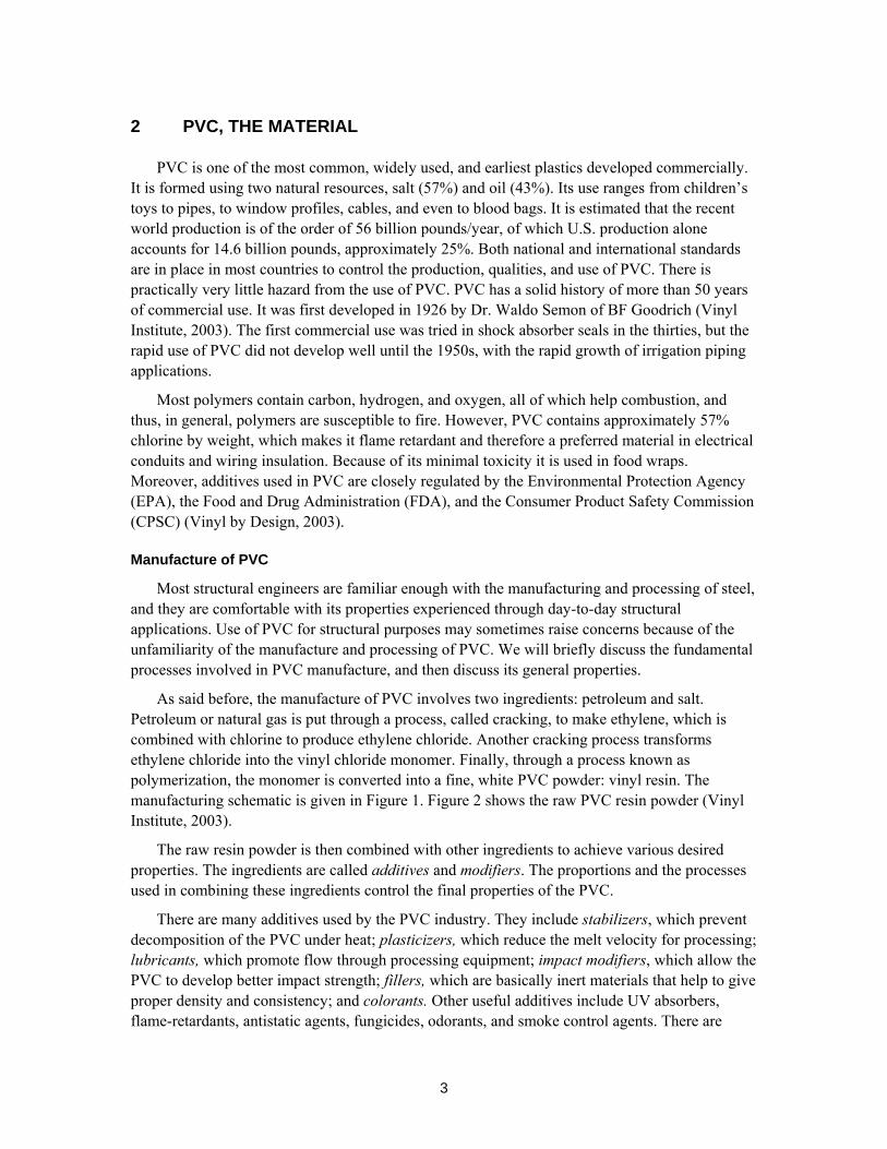
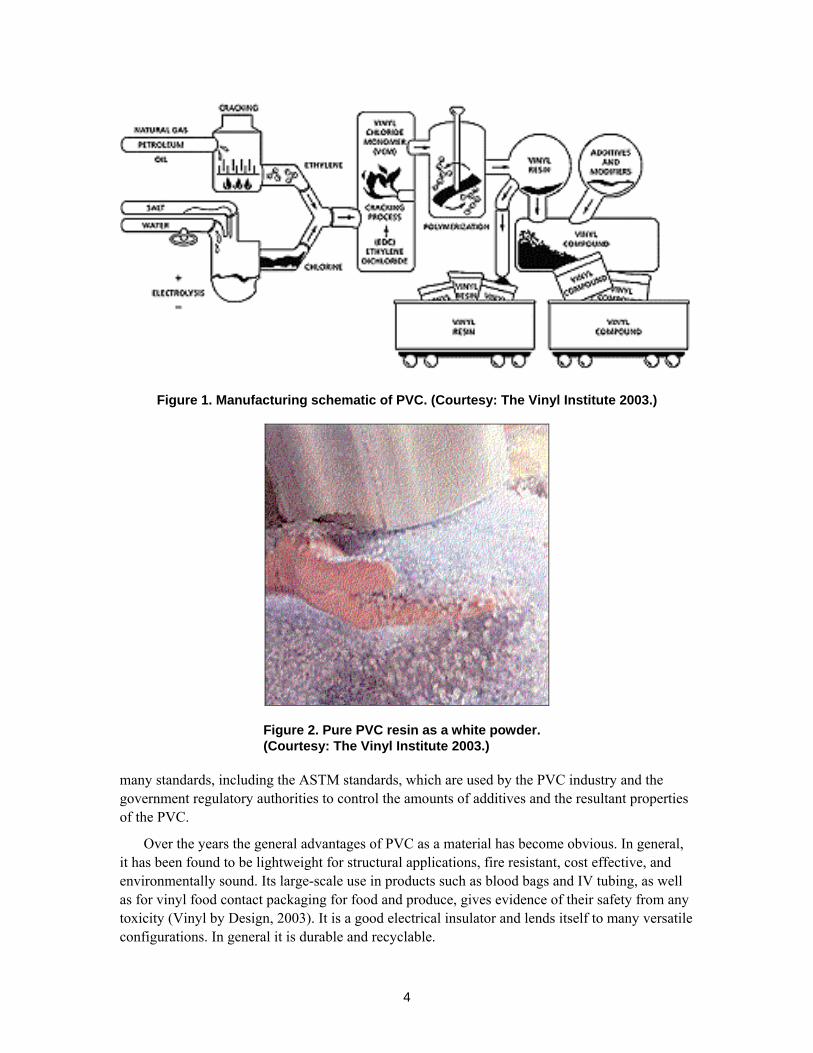
As said before, the manufacture of PVC involves two ingredients: petroleum and salt. Petroleum or natural gas is put through a process, called cracking, to make ethylene, which is combined with chlorine to produce ethylene chloride. Another cracking process transforms ethylene chloride into the vinyl chloride monomer. Finally, through a process known as polymerization, the monomer is converted into a fine, white PVC powder: vinyl resin. The manufacturing schematic is given in Figure 1. Figure 2 shows the raw PVC resin powder (Vinyl Institute, 2003).
The raw resin powder is then combined with other ingredients to achieve various desired properties. The ingredients are called additives and modifiers. The proportions and the processes used in combining these ingredients control the final properties of the PVC.
There are many additives used by the PVC industry. They include stabilizers, which prevent decomposition of the PVC under heat; plasticizers, which reduce the melt velocity for processing; lubricants, which promote flow through processing equipment; impact modifiers, which allow the PVC to develop better impact strength; fillers, which are basically inert materials that help to give proper density and consistency; and colorants. Other useful additives include UV absorbers, flame-retardants, antistatic agents, fungicides, odorants, and smoke control agents. There are
4
Figure 1. Manufacturing schematic of PVC. (Courtesy: The Vinyl Institute 2003.)
Figure 2. Pure PVC resin as a white powder. (Courtesy: The Vinyl Institute 2003.)
many standards, including the ASTM standards, which are used by the PVC industry and the government regulatory authorities to control the amounts of additives and the resultant properties of the PVC.
Over the years the general advantages of PVC as a material has become obvious. In general, it has been found to be lightweight for structural applications, fire resistant, cost effective, and environmentally sound. Its large-scale use in products such as blood bags and IV tubing, as well as for vinyl food contact packaging for food and produce, gives evidence of their safety from any toxicity (Vinyl by Design, 2003). It is a good electrical insulator and lends itself to many versatile configurations. In general it is durable and recyclable.
5
PVC in building and construction
PVC has been used extensively in the building and construction industry for over fifty years. Vinyl windows have become very common. Other applications include fencing, railing, decking, floor and wall covering, cladding, and roofing. Because it is fairly impermeable, it is also used as a vapor barrier for trapping moisture inside the wall cavity. Flexible vinyl is used for sheathing electric cables and wires.
Fire performance
The fire performance of PVC depends largely on the exact combinations of additives and modifiers. Especially for use as insulating material for electrical use, PVC must meet the fire safety requirements of the National Fire Protection Association’s National Electrical Code. The high chlorine content of the PVC makes it inherently more flame resistant than most alternative materials in the electrical product industry. However, vinyl electrical products typically burn at above 600ºF when a flame or heat source is applied, but they usually self-extinguish when the flame source is removed (Vinyl by Design, 2003). When it burns, PVC releases significantly less heat than many other electrical insulation and jacketing materials. Like many other similar products, PVC’s combustion products are toxic. Burning produces carbon dioxide and carbon monoxide; the latter is extremely toxic.
Comparison of properties of PVC and steel
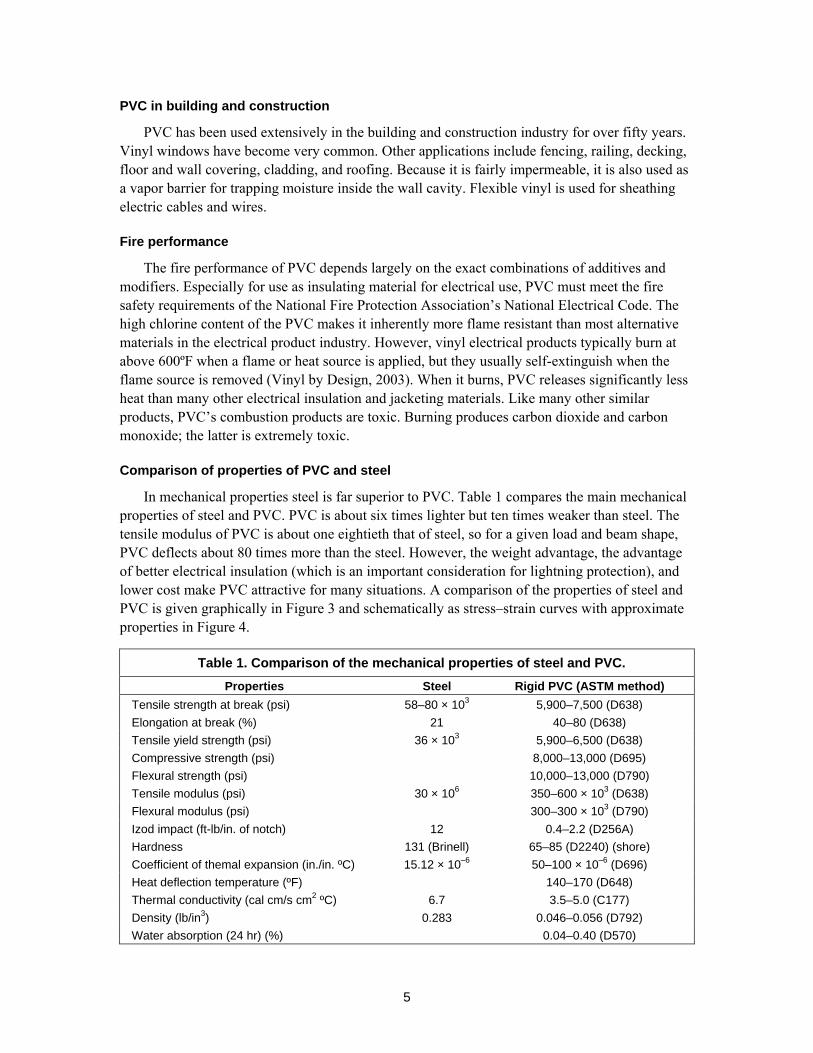
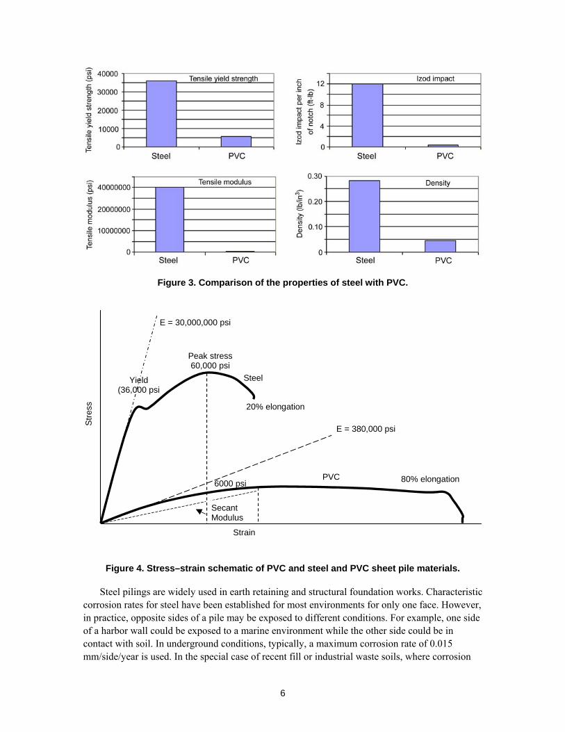
In mechanical properties steel is far superior to PVC. Table 1 compares the main mechanical properties of steel and PVC. PVC is about six times lighter but ten times weaker than steel. The tensile modulus of PVC is about one eightieth that of steel, so for a given load and beam shape, PVC deflects about 80 times more than the steel. However, the weight advantage, the advantage of better electrical insulation (which is an important consideration for lightning protection), and lower cost make PVC attractive for many situations. A comparison of the properties of steel and PVC is given graphically in Figure 3 and schematically as stress–strain curves with approximate properties in Figure 4.
Table 1. Comparison of the mechanical properties of steel and PVC. Properties Steel Rigid PVC (ASTM method)
Tensile strength at break (psi) 58–80 × 103 5,900–7,500 (D638) Elongation at break (%) 21 40–80 (D638) Tensile yield strength (psi) 36 × 103 5,900–6,500 (D638) Compressive strength (psi) 8,000–13,000 (D695) Flexural strength (psi) 10,000–13,000 (D790) Tensile modulus (psi) 30 × 106 350–600 × 103 (D638) Flexural modulus (psi) 300–300 × 103 (D790) Izod impact (ft-lb/in. of notch) 12 0.4–2.2 (D256A) Hardness 131 (Brinell) 65–85 (D2240) (shore) Coefficient of themal expansion (in./in. ºC) 15.12 × 10⁻⁶ 50–100 × 10–6 (D696) Heat deflection temperature (ºF) 140–170 (D648) Thermal conductivity (cal cm/s cm2 ºC) 6.7 3.5–5.0 (C177) Density (lb/in3) 0.283 0.046–0.056 (D792) Water absorption (24 hr) (%) 0.04–0.40 (D570)
6
Figure 3. Comparison of the properties of steel with PVC.
E = 30,000,000 psi
80% elongation
Secant Modulus
Stre
ss
Strain
Steel
PVC
Yield (36,000 psi
Peak stress60,000 psi
6000 psi
20% elongation
E = 380,000 psi
Figure 4. Stress–strain schematic of PVC and steel and PVC sheet pile materials.
Steel pilings are widely used in earth retaining and structural foundation works. Characteristic corrosion rates for steel have been established for most environments for only one face. However, in practice, opposite sides of a pile may be exposed to different conditions. For example, one side of a harbor wall could be exposed to a marine environment while the other side could be in contact with soil. In underground conditions, typically, a maximum corrosion rate of 0.015 mm/side/year is used. In the special case of recent fill or industrial waste soils, where corrosion
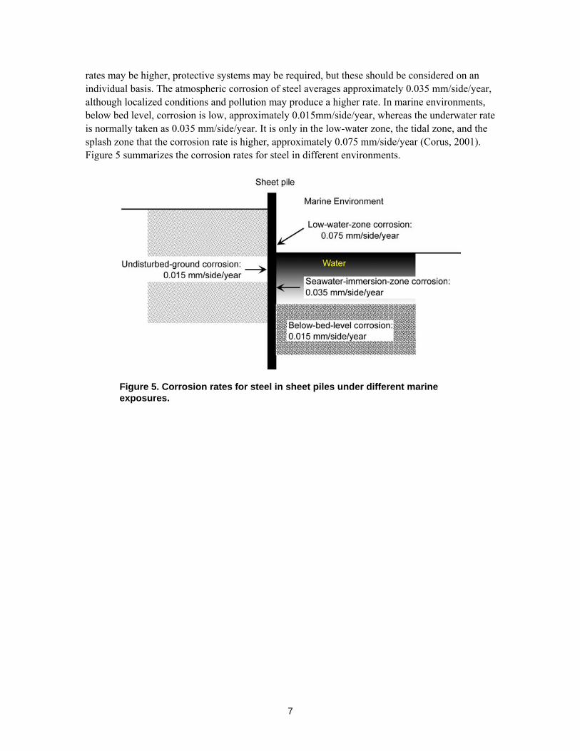
7
rates may be higher, protective systems may be required, but these should be considered on an individual basis. The atmospheric corrosion of steel averages approximately 0.035 mm/side/year, although localized conditions and pollution may produce a higher rate. In marine environments, below bed level, corrosion is low, approximately 0.015mm/side/year, whereas the underwater rate is normally taken as 0.035 mm/side/year. It is only in the low-water zone, the tidal zone, and the splash zone that the corrosion rate is higher, approximately 0.075 mm/side/year (Corus, 2001). Figure 5 summarizes the corrosion rates for steel in different environments.
Figure 5. Corrosion rates for steel in sheet piles under different marine exposures.
8
3 SHEET PILING AND ITS APPLICATIONS
What is sheet piling?
The term sheet piling in general is used for a wall that resists horizontal loads, as opposed to bearing piles, which are isolated and take loads, which are normally vertical or along the axis of the piles. However, under certain circumstances, sheet piling can also carry some vertical loading. Timber, steel, and reinforced concrete used to be the traditional materials for sheet piling until about 15–20 years ago, with the advent of vinyl sheet piling, and then later, composite sheet piles. Overall costs frequently dictate the material used. Steel sheet piles dominate the market, and a significant proportion employed in temporary work is extracted and reused one or more times.
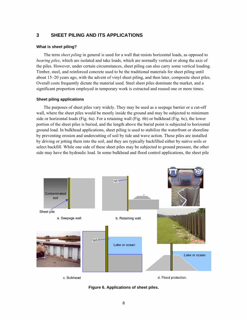
Sheet piling applications
The purposes of sheet piles vary widely. They may be used as a seepage barrier or a cut-off wall, where the sheet piles would be mostly inside the ground and may be subjected to minimum side or horizontal loads (Fig. 6a). For a retaining wall (Fig. 6b) or bulkhead (Fig. 6c), the lower portion of the sheet piles is buried, and the length above the burial point is subjected to horizontal ground load. In bulkhead applications, sheet piling is used to stabilize the waterfront or shoreline by preventing erosion and undercutting of soil by tide and wave action. These piles are installed by driving or jetting them into the soil, and they are typically backfilled either by native soils or select backfill. While one side of these sheet piles may be subjected to ground pressure, the other side may have the hydraulic load. In some bulkhead and flood control applications, the sheet pile
Figure 6. Applications of sheet piles.
9
may stick out above the ground level (Fig. 6d) and the water level may rise against the sheet pile wall. In these applications the integrity of the wall should be adequate to resist the hydraulic load and the storm wave impacts. Most retaining walls and flood walls have anchor bolts to stabilize the wall from the excessive backpressure of the ground. Engineering design guidance documents are usually available from the suppliers of the sheet piles for use in designing the sheet pile walls and their driving methods.
General guidance
The U.S. Army Corps of Engineers Engineering Manual, EM 1110-2-2504 of 1994, gives the guidelines for sheet piling installation with recommendation for proper coordination among hydraulic, geotechnical, and structural engineers. Final decisions are usually taken after close coordination between design engineers and local interests for alignment and construction. Geotechnical considerations are paramount in determining the driving conditions and stability. Structural considerations will lead to the decision on the wall type (cantilever vs. anchored type), materials (heavy-gauge steel, light gauge steel, wood, concrete, PVC, or composite). The designer must consider the possibility of material deterioration and its effect on the structural integrity of the system.
Basic engineering design considerations
Sheet piles basically work as cantilever beams. For a given load condition, the stresses and deflections in beams are primarily controlled by two basic parameters: E, the modulus of elasticity of the material, and I, the moment of inertia. While E is the fundamental property of the material, I depends on the thickness and section profile of the beam. The corrugation provided by the ‘Z’ shape of the common sheet piles simply enhances the value of I. A cursory look at the heavier-duty sheet piles of any of the manufacturers would show higher section depths and thicker gages. The key design equation for limiting beam deflection takes the form
δ = f(P)/(EI)
which shows that the deflection δ depends on the product EI, which is called flexural stiffness. The higher the value of EI, the lower will be the deflection. As we discussed before, because the value of E for steel is so high (i.e. 30 × 106 psi, as opposed to 0.38 × 10⁶ psi for PVC), for the same section profile (i.e. the same moment of inertia), the deflection of the PVC sheet pile would be 30/0.38, or approximately 80, times more than steel.
The work performed by the ERDC Construction Engineering Research Laboratory, Champaign, IL, (Lampo et al., 1998) under the Construction Productivity Advancement Program (CPAR) has defined three classes of commercial sheet piles:
• Light duty: Minimum EI = 2.48 × 10⁵ kip-in2/ft • Medium duty: Minimum EI = 1.0 × 10⁶ kip-in2/ft • Heavy duty: Minimum EI = 5.5 × 10⁶ kip-in2/ft. The values of moment of inertia, I, of the heavy-duty PVC sheet piles available commercially
were observed to be around 90 in4/ft. For new installations of PVC sheet piles, E = 375,000 psi and I = 90 kip-in2/ft, so EI is 33.8 × 10⁶ kip-in2/ft, which definitely meets the heavy-duty requirement.
10
Mechanical properties
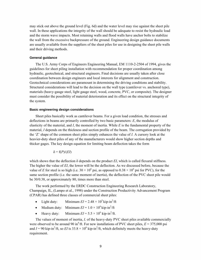
Modulus of elasticity
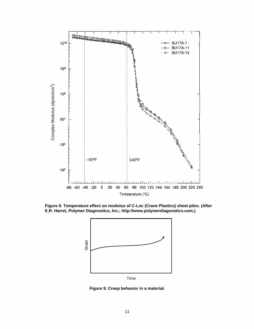
We have shown that the modulus of elasticity, E, is an important design consideration. In axial tests (compression or tensile), the stress–strain curves of PVC are non-linear, so one needs to consider both the tangent modulus and the secant modulus (Fig. 7). The tangent modulus is larger than the secant modulus. In high-load applications the use of the secant modulus is more appropriate for precise deflection calculations. Because sheet piles are manufactured by an extrusion process, one must determine whether any directionalities of the properties are induced in the material. A recent study of a manufactured vinyl sheet pile by Tom and Tom (2002) of ERDC-GSL has shown that there is no significant anisotropy in the material. Temperature has a significant effect on the elasticity modulus. The modulus increases at lower temperatures and decreases at higher temperatures. Tests performed on a commercial sheet piling PVC (Fig. 8) have shown that above 140ºF the reduction of modulus is significant, and above 180ºF the modulus reduces drastically.
Strain
Tangent Modulus
Stre
ss Secant
Modulus
Figure 7. Stress–strain curve of a visco-elastic material.
Strength
The other most important property is strength. Both tensile and compressive yield strengths are important for determining at what loads or moments the sheet pile will fail. Of course the PVC sheet pile, given its high elongation property, can hardly fail under service load but may become very unstable from accidentally applied extreme overload. Flexural strength properties of the PVC sheet pile materials are also considered useful, especially to assess the deflection parameters directly under the flexural loads and their modes of failure.
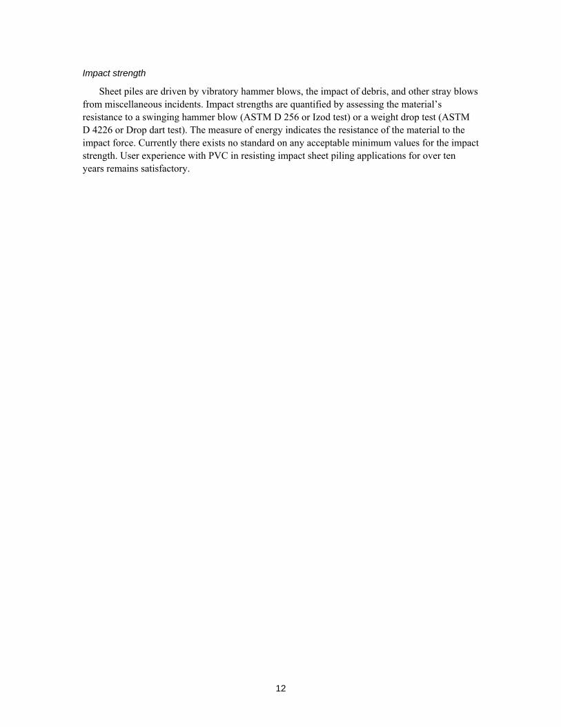
Creep
All visco-elastic materials suffer creep, in which the material continues to deform under a sustained constant load until it fails (Fig. 9). At low loads, creep is hardly a problem, because it takes an extremely long time to deform; however, at a higher applied load, PVC may creep, and a higher temperature may accelerate the creep deformation.
11
-40F 140F-40F 140F-40F 140F–40ºF 140ºF
Com
plex
Mod
ulus
(dyn
es/c
m2 )
Figure 8. Temperature effect on modulus of C-Loc (Crane Plastics) sheet piles. (After E.R. Harrel, Polymer Diagnostics, Inc.; http://www.polymerdiagnostics.com.)
Stra
in
Time
Figure 9. Creep behavior in a material.
12
Impact strength
Sheet piles are driven by vibratory hammer blows, the impact of debris, and other stray blows from miscellaneous incidents. Impact strengths are quantified by assessing the material’s resistance to a swinging hammer blow (ASTM D 256 or Izod test) or a weight drop test (ASTM D 4226 or Drop dart test). The measure of energy indicates the resistance of the material to the impact force. Currently there exists no standard on any acceptable minimum values for the impact strength. User experience with PVC in resisting impact sheet piling applications for over ten years remains satisfactory.
13
4 REVIEW OF LITERATURE AND MANUFACTURERS’ DATA
Parameters of PVC degradation
The degradation of mechanical properties over time discussed in the previous section is of concern for the users of sheet piles. The outdoor atmospheric exposure parameters, which influence the mechanical properties of PVC in sheet piles, include UV radiation, air temperature, rain, pollutants, and relative humidity.
The dosage of UV (ultraviolet energy) from solar radiation varies with location. The wavelengths of the radiation that are of most concern are in the range of 295–380 nanometers (nm). At these wavelengths, the UV has sufficient energy to break the chemical bonds (Summers and Rabinovitch, 1999). Outdoor air temperatures usually vary between –40º and 120ºF, but when exposed to the sun, sheet pile temperatures may exceed 120ºF, because they would be the composite of air temperature, infrared radiation, effect of wind, and surface evaporation of water. Rainfall varies with location, ranging from 0 to 100 inches per year. Rain usually washes away the loose materials from the sheet pile surface, but it may also deposit dissolved gas if it reacts with the PVC. The atmospheric relative humidity usually varies between 10 and 100%, and sometimes it may allow pollutants to be deposited on the surface of the sheet piles. The range of pollutants is variable and includes CO2, NO2, O3, SO2, and dust.
Changes in properties during weathering
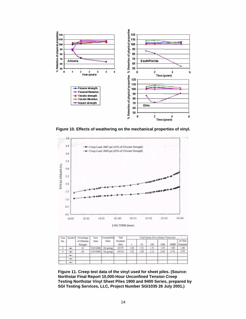
The chemical degradation processes of PVC have been well studied and well summarized by Rabinovitch et al. (1993a, 1993b). These processes lead to discoloration, surface erosion, and embrittlement. However, this type of aging is limited to a depth of no more than 150 micrometer (0.006 in). Rabinovitch and her coworkers weathered extruded rigid PVC samples at 45º facing south, according to ASTM D1435, in Arizona (hot, dry, high-UV climate), Florida (hot, humid, high-UV climate), and Ohio (northern industrial climate). The exposure was continued for one, two, and five years. Mechanical properties were then measured on the exposed and unexposed samples. Figure 10 shows the mechanical properties as they changed over the five years. The data indicate that in general, properties such as flexural strength, flexural modulus, tensile strength, and tensile modulus do not change or, if anything, increase very slightly during the five years of outdoor exposure for all U.S. climates. However, the data also show that, in contrast with the above properties, the impact strength decreases significantly over time, with the greatest reduction observed in hot, high-UV climates of Arizona and Florida.
Changes in creep properties
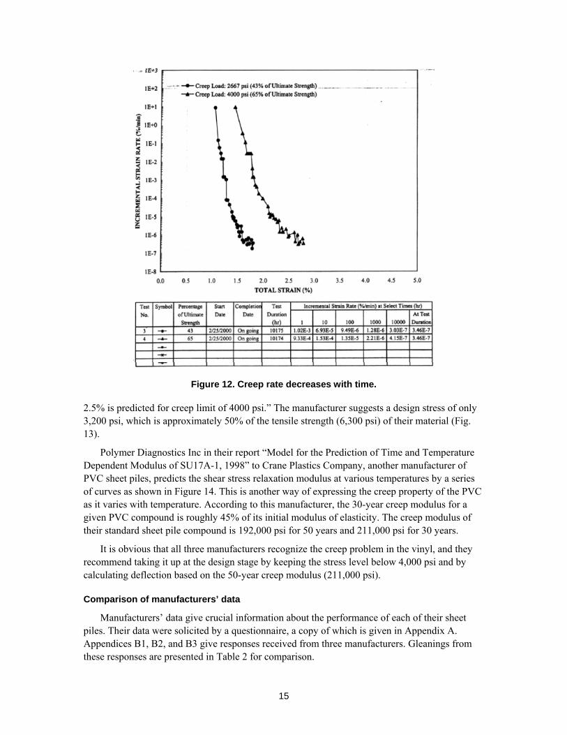
Unconfined tension creep tests were performed on vinyl sheet piling materials by one of the manufacturers according to the ASTM test method D5262-92. At the test duration of 10,000 hours the total strain was 1.80% for a constant load of 43% of ultimate strength, and 2.78% for a constant load of 65%. The progressive increase in strain with time is shown in Figure 11, and the progressive decrease in the strain rate in Figure 12.
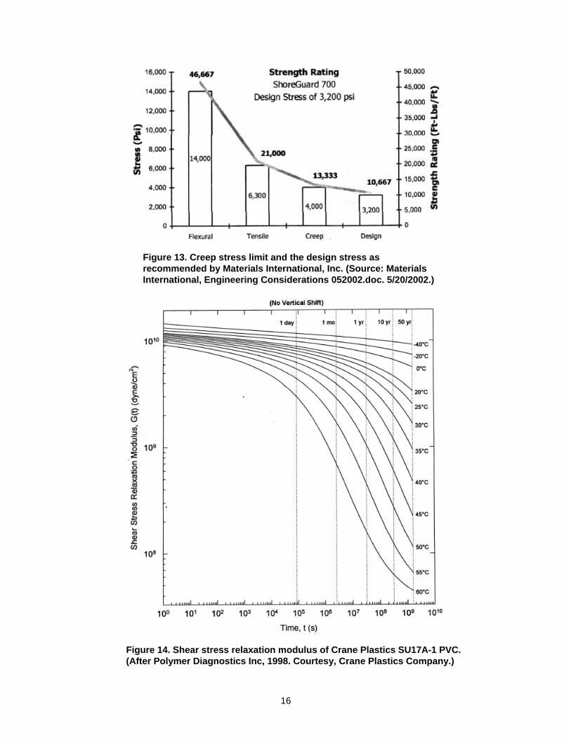
Regarding creep, another manufacturer (Materials International) notes “Creep failure is the deformation or plastic flow of the vinyl when subjected to constant loading over time and can be precluded if the stresses are maintained below 5% strain. A 75-year tensile strain on the order of
14
Figure 10. Effects of weathering on the mechanical properties of vinyl.
Figure 11. Creep test data of the vinyl used for sheet piles. (Source: Northstar Final Report 10,000-Hour Unconfined Tension Creep Testing Northstar Vinyl Sheet Piles 1900 and 9400 Series, prepared by SGI Testing Services, LLC, Project Number SGI1035 26 July 2001.)
15
Figure 12. Creep rate decreases with time.
2.5% is predicted for creep limit of 4000 psi.” The manufacturer suggests a design stress of only 3,200 psi, which is approximately 50% of the tensile strength (6,300 psi) of their material (Fig. 13).
Polymer Diagnostics Inc in their report “Model for the Prediction of Time and Temperature Dependent Modulus of SU17A-1, 1998” to Crane Plastics Company, another manufacturer of PVC sheet piles, predicts the shear stress relaxation modulus at various temperatures by a series of curves as shown in Figure 14. This is another way of expressing the creep property of the PVC as it varies with temperature. According to this manufacturer, the 30-year creep modulus for a given PVC compound is roughly 45% of its initial modulus of elasticity. The creep modulus of their standard sheet pile compound is 192,000 psi for 50 years and 211,000 psi for 30 years.
It is obvious that all three manufacturers recognize the creep problem in the vinyl, and they recommend taking it up at the design stage by keeping the stress level below 4,000 psi and by calculating deflection based on the 50-year creep modulus (211,000 psi).
Comparison of manufacturers’ data
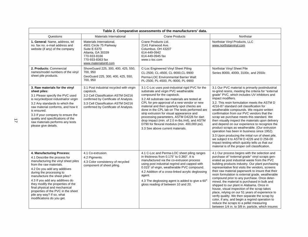
Manufacturers’ data give crucial information about the performance of each of their sheet piles. Their data were solicited by a questionnaire, a copy of which is given in Appendix A. Appendices B1, B2, and B3 give responses received from three manufacturers. Gleanings from these responses are presented in Table 2 for comparison.
16
Figure 13. Creep stress limit and the design stress as recommended by Materials International, Inc. (Source: Materials International, Engineering Considerations 052002.doc. 5/20/2002.)
Figure 14. Shear stress relaxation modulus of Crane Plastics SU17A-1 PVC. (After Polymer Diagnostics Inc, 1998. Courtesy, Crane Plastics Company.)
17
Table 2. Comparative assessments of the manufacturers’ data. Questions Materials International Crane Products Northstar
1. General: Name, address, tel no. fax no. e-mail address and website (if any) of the company
Materials International, 4501 Circle 75 Parkway Suite E-5370 Atlanta, GA 30339 770-933-8166 770-933-8363 fax www.materialsintl.com
Crane Products Ltd. 2141 Fairwood Ave. Columbus, OH 43207 614-449-0942 614-449-0945 fax www.c-loc.com
Northstar Vinyl Products, LLC www.northstarvinyl.com
2. Products: Commercial names/model numbers of the vinyl sheet pile products.
ShoreGuard 225, 300, 400, 425, 550, 700, 950 GeoGuard 225, 300, 400, 425, 550, 700, 950
C-Loc Engineered Vinyl Sheet Piling CL-2500, CL-4500, CL-9000,CL-9900 Perma-LOC Environmental Barrier Wall: PL-2500, PL-4500, PL-9000, PL-9900
Northstar Vinyl Sheet Pile Series 8000i, 4000i, 3100c, and 2550c
3. Raw materials for the vinyl sheet piles: 3.1 Please specify the PVC used is recycled/post industrial/or virgin 3.2 Any standards to which the raw material conforms, and how it is ensured. 3.3 If your company to ensure the quality and specifications of the raw materials performs any tests please give details.
3.1 Post industrial recycled with virgin capstock. 3.2 Cell Classification ASTM D4216 confirmed by Certificate of Analysis. 3.3 Cell Classification ASTM D4216 confirmed by Certificate of Analysis.
3.1 C-Loc uses post-industrial rigid PVC for the substrate and virgin PVC weatherable compound for the capstock. 3.2 All substrate raw materials are tested at CPL for pre-approval of a new vendor or new material and then quarterly spot checks are done in the CPL lab on The tests performed are strip extrusion for visual appearance and processing parameters, ASTM D4226 for dart drop impact (min. of 2.0 in-lbs./mil), and ASTM D790 for flexural modulus (min. 400,000 psi). 3.3 See above current materials.
3.1 Our PVC material is primarily postindustrial re-grind resins, meeting the criteria for “external grade” PVC, which includes UV inhibitors and impact modifiers. 3.2. This resin formulation meets the ASTM D 4216-87 standard cell classification for weatherable compounds. We require written confirmation from our PVC vendors that the scrap we purchase meets this standard. We then visually inspect the materials upon delivery and depend on our experience to recognize the product scraps as weatherable. (Our extrusion operation has been in business since 1952). 3.3 Upon producing the initial run of sheet pile, we subject it to ASTM D 4226 and D 256-00 impact testing which quickly tells us that our material is of the proper cell classification.
4. Manufacturing Process: 4.1 Describe the process for manufacturing the vinyl sheet piles from the raw materials. 4.2 Do you add any additives during the processing to manufacture the sheet piles? 4.3 If you add any additives do they modify the properties of the final physical and mechanical properties of the PVC in the sheet pile any way? If so, what modifications do you get.
4.1 Co-extrusion. 4.2 Pigments. 4.3 Color consistency of recycled component of sheet piling.
4.1 C-Loc and Perma-LOC sheet piling ranges in thickness from 0.175” to 0.360”. It is manufactured via the co-extrusion process using post industrial regrind and capped with 0.015” of virgin, weatherable PVC compound. 4.2 Addition of a cross-linked acrylic deglossing agent.
4.3 The deglossing agent is added to give a 60º gloss reading of between 10 and 20.
4.1 Our process begins with the selection and purchase of “external grade” vinyl scraps gen-erated as post industrial waste from the PVC building products industry. Our plant purchasing representative first visits the vendors, screens their raw material paperwork to insure that their resin formulation is external grade, weatherable compound prior to any purchase. Once deter-mined, the material is purchased in bulk and shipped to our plant in Alabama. Once in house, visual inspection of the scrap takes place, relying on our 51 years of experience to verify quality. We then separate the scrap by color, if any, and begin a regrind operation to reduce the scraps to a pellet measuring between 1/4 in. to 3/8 in. particle, which insures
18
a smooth conversion in the extruder. We send the ground resins through a metal detector and separator to insure no foreign materials are present. The resins are fed into a hopper that smoothly feeds the extruder barrel. This barrel contains heating elements that convert the pel-lets into a molten, flowable vinyl that is extruded through a mono-extrusion die positioned at the other end. Using a mono-extrusion process insures that the resins are bonded at identical temperatures throughout the cross section, precluding any possibility of delamination problems. Northstar chooses to mono-extruded through a die (see below) to create a high performance monolithic piece. Unlike “co-extruded” parts which consist of an inexpensive substrate laminated with a “paper” thin layer of weatherable capstock material, mono-extruded pieces do not delami-nate and function as one unit as demonstrated by flexural, tensile, and creep testing. Mono-extrusion has withstood the test of time; the oldest vinyl seawalls that are in existence are ones that were mono-extruded. The molten PVC material exits the die as a formed piece, which then goes through a series of “sizers” that bring the product into proper tolerance as it goes through cooling baths in order to set the final shape. As the product exits the baths, it is cut into specific lengths by an automatic circular saw, palletized, banded and prepared for shipment. 4.2 The only additives added to this process would be small amounts of colored virgin resin in order to obtain a consistent color balance. 4.3 The addition of a small amount of virgin resin has no effect whatsoever on the physical or chemical properties of the finished products.
5. Testing of Products: What testing, if any, you perform on the manufactured sheet piles to make the products conform to the declared specifications of your products. Please mention if those tests conform to any ASTM or any other nationally recognized tests.
Bench Testing, Field Testing, Quality Control Testing, ASTM D4216, ASTM D4226, ASTM D256, ASTM D638, ASTM D790, ASTM D1435
Add anything from the attached QCS sheet for the CL9000 or the QC impact test. (Note: I have the QCS and CL9000 hard copies if anyone needs them. -PKD)
Our final product testing begins with constant visual inspection and random caliper measurements to insure that the product is within acceptable physical dimensions according to our specifications. [Rest of the response is attached as Attachment #1]
6. Specifications: See Appendix See Appendix See Appendix
19
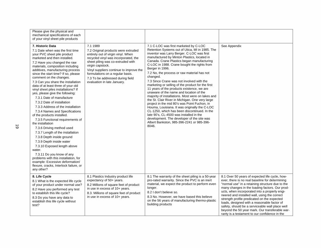
Please give the physical and mechanical specifications of each of your vinyl sheet pile products
7. Historic Data 7.1 Date when was the first time your PVC sheet pile product marketed and then installed. 7.2 Have you changed the raw materials, composition including additives, manufacturing process since the start time? If so, please comment on the changes. 7.3 Can you share the installation data of at least three of your old vinyl sheet piles installations? If yes, please give the following: 7.3.1 Date of manufacture 7.3.2 Date of installation 7.3.3 Address of the installation 7.3.4 Names and Specifications of the products installed. 7.3.5 Functional requirements of the installation 7.3.6 Driving method used 7.3.7 Length of the installation 7.3.8 Depth inside ground 7.3.9 Depth inside water 7.3.10 Exposed length above water. 7.3.11 Do you know of any problems with this installation, for example: Excessive deformation/ flexure, cracks, Interlock failure, or any other?
7.1 1989 7.2 Original products were extruded entirely out of virgin vinyl. When recycled vinyl was incorporated, the sheet piling was co-extruded with virgin capstock. Vinyl suppliers continue to improve the formulations on a regular basis. 7.3 To be addressed during field evaluation in late January.
7.1 C-LOC was first marketed by C-LOC Retention Systems out of Utica, MI in 1985. The inventor was Larry Berger. C-LOC was first manufactured by Minton Plastics, located in Canada. Crane Plastics began manufacturing C-LOC in 1988. Crane bought the rights from Berger in 1996. 7.2 No, the process or raw material has not changed. 7.3 Since Crane was not involved with the marketing or selling of the product for the first 11 years of the products existence, we are unaware of the name and location of the majority of installations. Most were on lakes and the St. Clair River in Michigan. One very large project in the mid 80’s was Point Fuchon, in Houma, Louisiana. It was originally the C-LOC CL-1250, which has been discontinued. In the late 90’s, CL-4500 was installed in the development. The developer of the site was Albert Bankston, 985-396-2241 or 985-396-8046.
See Appendix
8. Life Cycle 8.1 What is the expected life cycle of your product under normal use? 8.2 Have you performed any test to establish this life cycle? 8.3 Do you have any data to establish this life cycle without test?
8.1 Plastics Industry product life expectancy of 50+ years. 8.2 Millions of square feet of product in use in excess of 10+ years. 8.3. Millions of square feet of product in use in excess of 10+ years.
8.1 The warranty of the sheet piling is a 50-year pro-rated warranty. Since the PVC is an inert material, we expect the product to perform even longer. 8.2 I don’t believe so. 8.3 No. However, we have based this believe on the 56 years of manufacturing thermo-plastic building products
8.1 Over 50 years of expected life cycle, how-ever, there is no real baseline for determining “normal use” in a retaining structure due to the many changes in the loading factors. Our prod-ucts, when incorporated into a properly engi-neered and installed wall, using the correct strength profile predicated on the expected loads, designed with a reasonable factor of safety, should be a serviceable wall place well beyond the 50 year mark. Our transferable war-ranty is a testament to our confidence in the
20
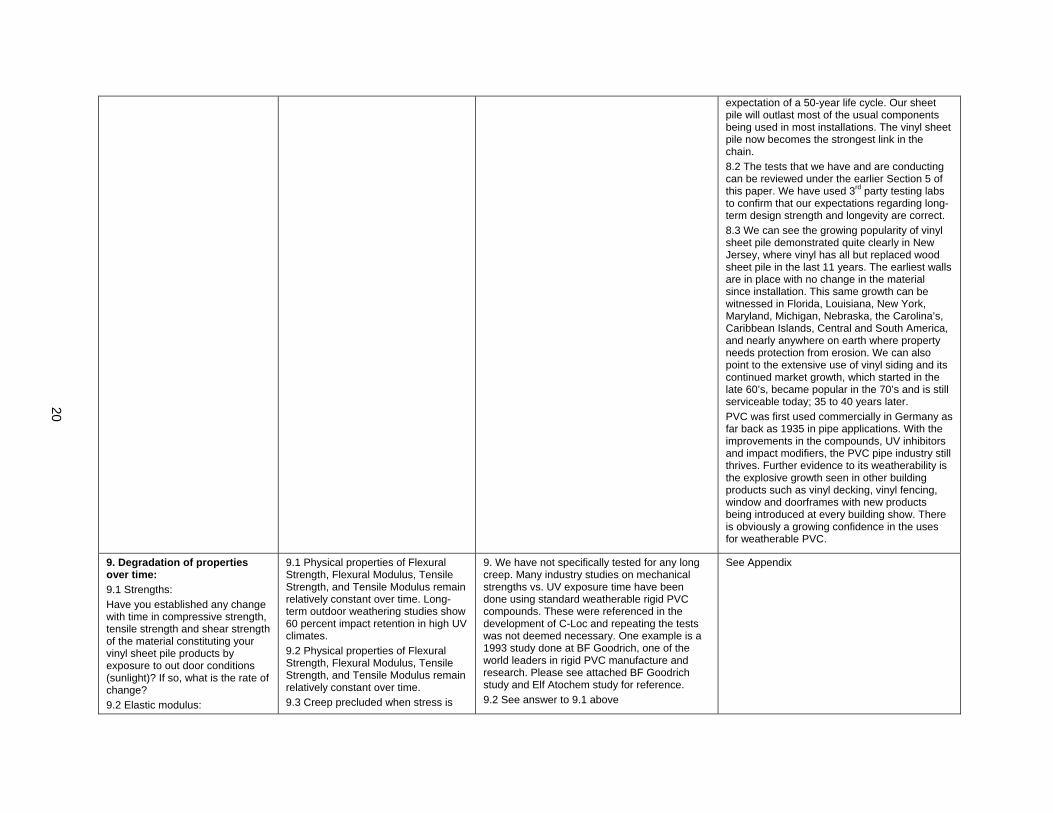
expectation of a 50-year life cycle. Our sheet pile will outlast most of the usual components being used in most installations. The vinyl sheet pile now becomes the strongest link in the chain. 8.2 The tests that we have and are conducting can be reviewed under the earlier Section 5 of this paper. We have used 3rd party testing labs to confirm that our expectations regarding long-term design strength and longevity are correct. 8.3 We can see the growing popularity of vinyl sheet pile demonstrated quite clearly in New Jersey, where vinyl has all but replaced wood sheet pile in the last 11 years. The earliest walls are in place with no change in the material since installation. This same growth can be witnessed in Florida, Louisiana, New York, Maryland, Michigan, Nebraska, the Carolina’s, Caribbean Islands, Central and South America, and nearly anywhere on earth where property needs protection from erosion. We can also point to the extensive use of vinyl siding and its continued market growth, which started in the late 60’s, became popular in the 70’s and is still serviceable today; 35 to 40 years later. PVC was first used commercially in Germany as far back as 1935 in pipe applications. With the improvements in the compounds, UV inhibitors and impact modifiers, the PVC pipe industry still thrives. Further evidence to its weatherability is the explosive growth seen in other building products such as vinyl decking, vinyl fencing, window and doorframes with new products being introduced at every building show. There is obviously a growing confidence in the uses for weatherable PVC.
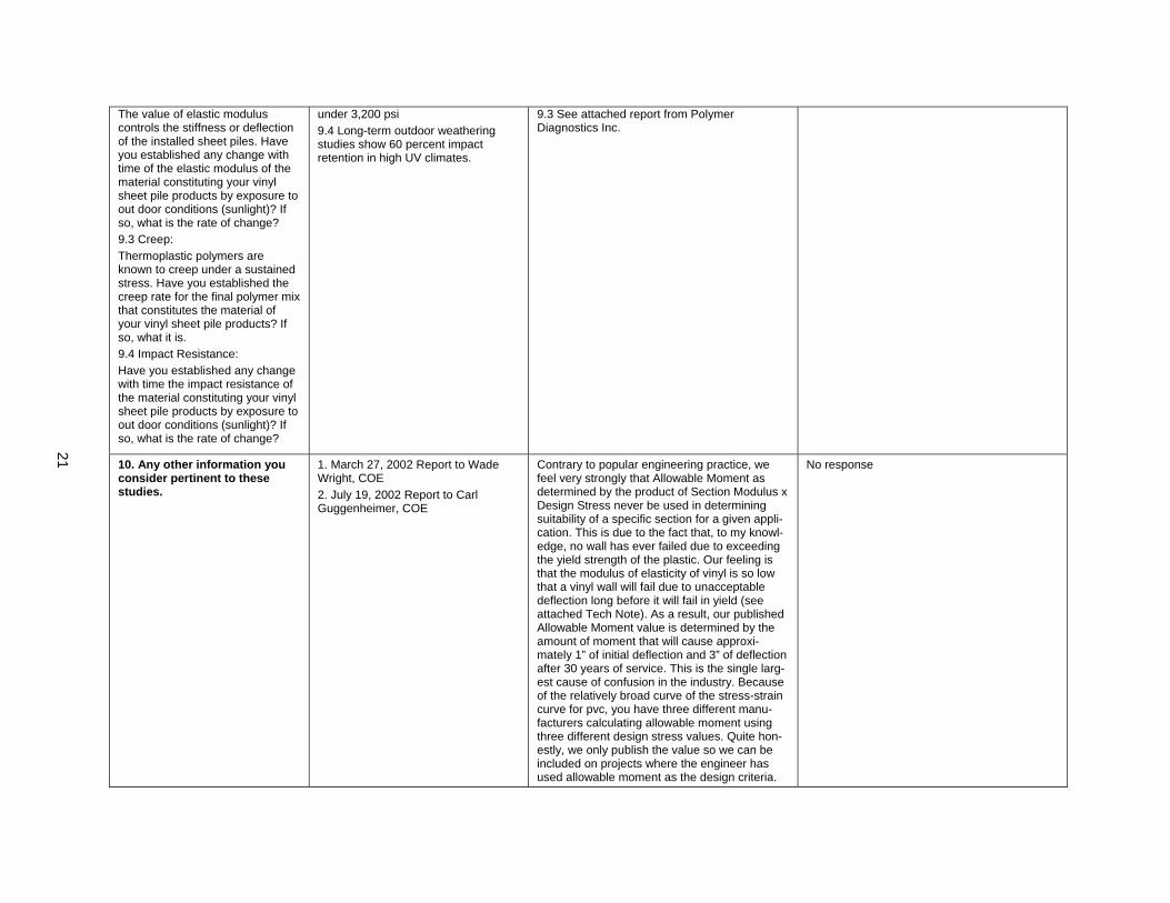
9. Degradation of properties over time: 9.1 Strengths: Have you established any change with time in compressive strength, tensile strength and shear strength of the material constituting your vinyl sheet pile products by exposure to out door conditions (sunlight)? If so, what is the rate of change? 9.2 Elastic modulus:
9.1 Physical properties of Flexural Strength, Flexural Modulus, Tensile Strength, and Tensile Modulus remain relatively constant over time. Long-term outdoor weathering studies show 60 percent impact retention in high UV climates. 9.2 Physical properties of Flexural Strength, Flexural Modulus, Tensile Strength, and Tensile Modulus remain relatively constant over time. 9.3 Creep precluded when stress is
9. We have not specifically tested for any long creep. Many industry studies on mechanical strengths vs. UV exposure time have been done using standard weatherable rigid PVC compounds. These were referenced in the development of C-Loc and repeating the tests was not deemed necessary. One example is a 1993 study done at BF Goodrich, one of the world leaders in rigid PVC manufacture and research. Please see attached BF Goodrich study and Elf Atochem study for reference. 9.2 See answer to 9.1 above
See Appendix
21
The value of elastic modulus controls the stiffness or deflection of the installed sheet piles. Have you established any change with time of the elastic modulus of the material constituting your vinyl sheet pile products by exposure to out door conditions (sunlight)? If so, what is the rate of change? 9.3 Creep: Thermoplastic polymers are known to creep under a sustained stress. Have you established the creep rate for the final polymer mix that constitutes the material of your vinyl sheet pile products? If so, what it is. 9.4 Impact Resistance: Have you established any change with time the impact resistance of the material constituting your vinyl sheet pile products by exposure to out door conditions (sunlight)? If so, what is the rate of change?
under 3,200 psi 9.4 Long-term outdoor weathering studies show 60 percent impact retention in high UV climates.
9.3 See attached report from Polymer Diagnostics Inc.
10. Any other information you consider pertinent to these studies.
1. March 27, 2002 Report to Wade Wright, COE 2. July 19, 2002 Report to Carl Guggenheimer, COE
Contrary to popular engineering practice, we feel very strongly that Allowable Moment as determined by the product of Section Modulus x Design Stress never be used in determining suitability of a specific section for a given appli-cation. This is due to the fact that, to my knowl-edge, no wall has ever failed due to exceeding the yield strength of the plastic. Our feeling is that the modulus of elasticity of vinyl is so low that a vinyl wall will fail due to unacceptable deflection long before it will fail in yield (see attached Tech Note). As a result, our published Allowable Moment value is determined by the amount of moment that will cause approxi-mately 1” of initial deflection and 3” of deflection after 30 years of service. This is the single larg-est cause of confusion in the industry. Because of the relatively broad curve of the stress-strain curve for pvc, you have three different manu-facturers calculating allowable moment using three different design stress values. Quite hon-estly, we only publish the value so we can be included on projects where the engineer has used allowable moment as the design criteria.
No response
22
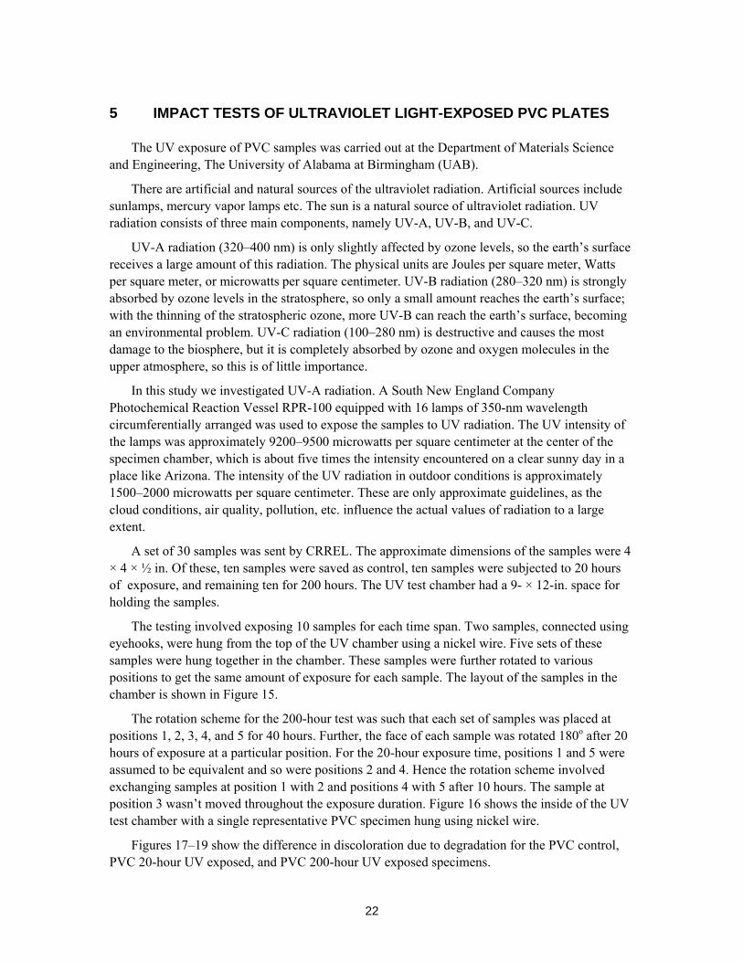
5 IMPACT TESTS OF ULTRAVIOLET LIGHT-EXPOSED PVC PLATES
The UV exposure of PVC samples was carried out at the Department of Materials Science and Engineering, The University of Alabama at Birmingham (UAB).
There are artificial and natural sources of the ultraviolet radiation. Artificial sources include sunlamps, mercury vapor lamps etc. The sun is a natural source of ultraviolet radiation. UV radiation consists of three main components, namely UV-A, UV-B, and UV-C.
UV-A radiation (320–400 nm) is only slightly affected by ozone levels, so the earth’s surface receives a large amount of this radiation. The physical units are Joules per square meter, Watts per square meter, or microwatts per square centimeter. UV-B radiation (280–320 nm) is strongly absorbed by ozone levels in the stratosphere, so only a small amount reaches the earth’s surface; with the thinning of the stratospheric ozone, more UV-B can reach the earth’s surface, becoming an environmental problem. UV-C radiation (100–280 nm) is destructive and causes the most damage to the biosphere, but it is completely absorbed by ozone and oxygen molecules in the upper atmosphere, so this is of little importance.
In this study we investigated UV-A radiation. A South New England Company Photochemical Reaction Vessel RPR-100 equipped with 16 lamps of 350-nm wavelength circumferentially arranged was used to expose the samples to UV radiation. The UV intensity of the lamps was approximately 9200–9500 microwatts per square centimeter at the center of the specimen chamber, which is about five times the intensity encountered on a clear sunny day in a place like Arizona. The intensity of the UV radiation in outdoor conditions is approximately 1500–2000 microwatts per square centimeter. These are only approximate guidelines, as the cloud conditions, air quality, pollution, etc. influence the actual values of radiation to a large extent.
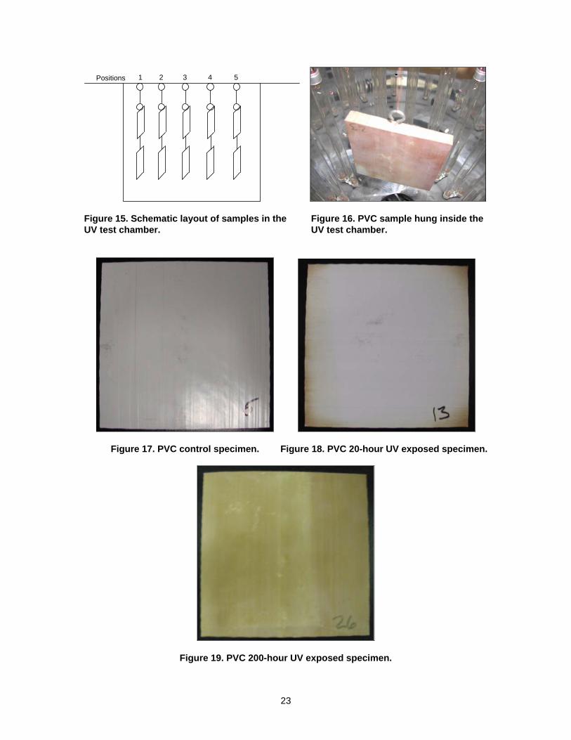
A set of 30 samples was sent by CRREL. The approximate dimensions of the samples were 4 × 4 × ½ in. Of these, ten samples were saved as control, ten samples were subjected to 20 hours of exposure, and remaining ten for 200 hours. The UV test chamber had a 9- × 12-in. space for holding the samples.
The testing involved exposing 10 samples for each time span. Two samples, connected using eyehooks, were hung from the top of the UV chamber using a nickel wire. Five sets of these samples were hung together in the chamber. These samples were further rotated to various positions to get the same amount of exposure for each sample. The layout of the samples in the chamber is shown in Figure 15.
The rotation scheme for the 200-hour test was such that each set of samples was placed at positions 1, 2, 3, 4, and 5 for 40 hours. Further, the face of each sample was rotated 180o after 20 hours of exposure at a particular position. For the 20-hour exposure time, positions 1 and 5 were assumed to be equivalent and so were positions 2 and 4. Hence the rotation scheme involved exchanging samples at position 1 with 2 and positions 4 with 5 after 10 hours. The sample at position 3 wasn’t moved throughout the exposure duration. Figure 16 shows the inside of the UV test chamber with a single representative PVC specimen hung using nickel wire.
Figures 17–19 show the difference in discoloration due to degradation for the PVC control, PVC 20-hour UV exposed, and PVC 200-hour UV exposed specimens.
23
Positions 1 2 3 4 5
Figure 15. Schematic layout of samples in the UV test chamber.
Figure 16. PVC sample hung inside the UV test chamber.
Figure 17. PVC control specimen. Figure 18. PVC 20-hour UV exposed specimen.
Figure 19. PVC 200-hour UV exposed specimen.
24
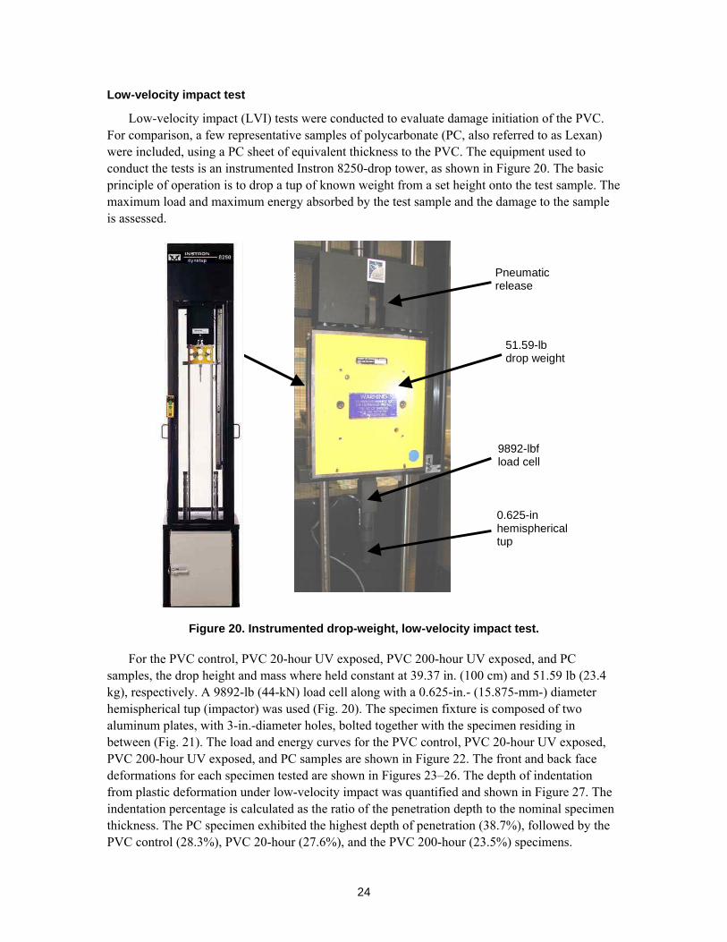
Low-velocity impact test
Low-velocity impact (LVI) tests were conducted to evaluate damage initiation of the PVC. For comparison, a few representative samples of polycarbonate (PC, also referred to as Lexan) were included, using a PC sheet of equivalent thickness to the PVC. The equipment used to conduct the tests is an instrumented Instron 8250-drop tower, as shown in Figure 20. The basic principle of operation is to drop a tup of known weight from a set height onto the test sample. The maximum load and maximum energy absorbed by the test sample and the damage to the sample is assessed.
0.625-in hemispherical tup
Pneumatic release
9892-lbf load cell
51.59-lb drop weight
Figure 20. Instrumented drop-weight, low-velocity impact test.
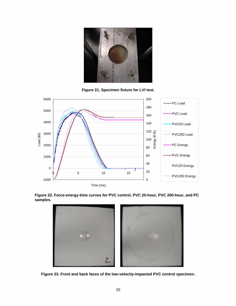
For the PVC control, PVC 20-hour UV exposed, PVC 200-hour UV exposed, and PC samples, the drop height and mass where held constant at 39.37 in. (100 cm) and 51.59 lb (23.4 kg), respectively. A 9892-lb (44-kN) load cell along with a 0.625-in.- (15.875-mm-) diameter hemispherical tup (impactor) was used (Fig. 20). The specimen fixture is composed of two aluminum plates, with 3-in.-diameter holes, bolted together with the specimen residing in between (Fig. 21). The load and energy curves for the PVC control, PVC 20-hour UV exposed, PVC 200-hour UV exposed, and PC samples are shown in Figure 22. The front and back face deformations for each specimen tested are shown in Figures 23–26. The depth of indentation from plastic deformation under low-velocity impact was quantified and shown in Figure 27. The indentation percentage is calculated as the ratio of the penetration depth to the nominal specimen thickness. The PC specimen exhibited the highest depth of penetration (38.7%), followed by the PVC control (28.3%), PVC 20-hour (27.6%), and the PVC 200-hour (23.5%) specimens.
25
Figure 21. Specimen fixture for LVI test.
-1000
0
1000
2000
3000
4000
5000
6000
0 5 10 15
Time (ms)
Load
(lbf
)
0
20
40
60
80
100
120
140
160
180
200
Ene
rgy
(ft-lb
)
PC Load
PVC Load
PVC20 Load
PVC200 Load
PC Energy
PVC Energy
PVC20 Energy
PVC200 Energy
Figure 22. Force-energy-time curves for PVC control, PVC 20-hour, PVC 200-hour, and PC samples.
Figure 23. Front and back faces of the low-velocity-impacted PVC control specimen.
26
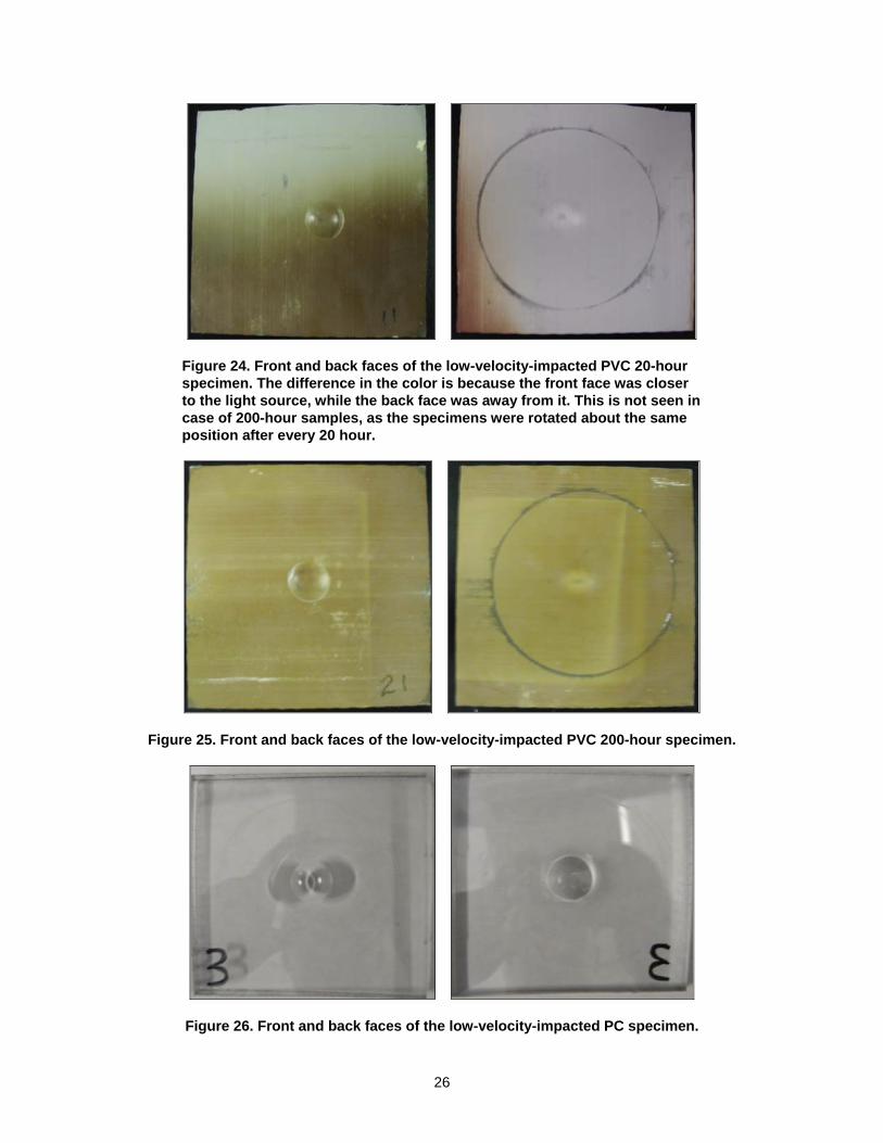
Figure 24. Front and back faces of the low-velocity-impacted PVC 20-hour specimen. The difference in the color is because the front face was closer to the light source, while the back face was away from it. This is not seen in case of 200-hour samples, as the specimens were rotated about the same position after every 20 hour.
Figure 25. Front and back faces of the low-velocity-impacted PVC 200-hour specimen.
Figure 26. Front and back faces of the low-velocity-impacted PC specimen.
27
0
1
2
3
4
5
6
0 1 2 3 4 5
Specimen
Inde
ntat
ion
dept
h (m
m)
PVC Control
PVC 20h
PVC 200h
PC
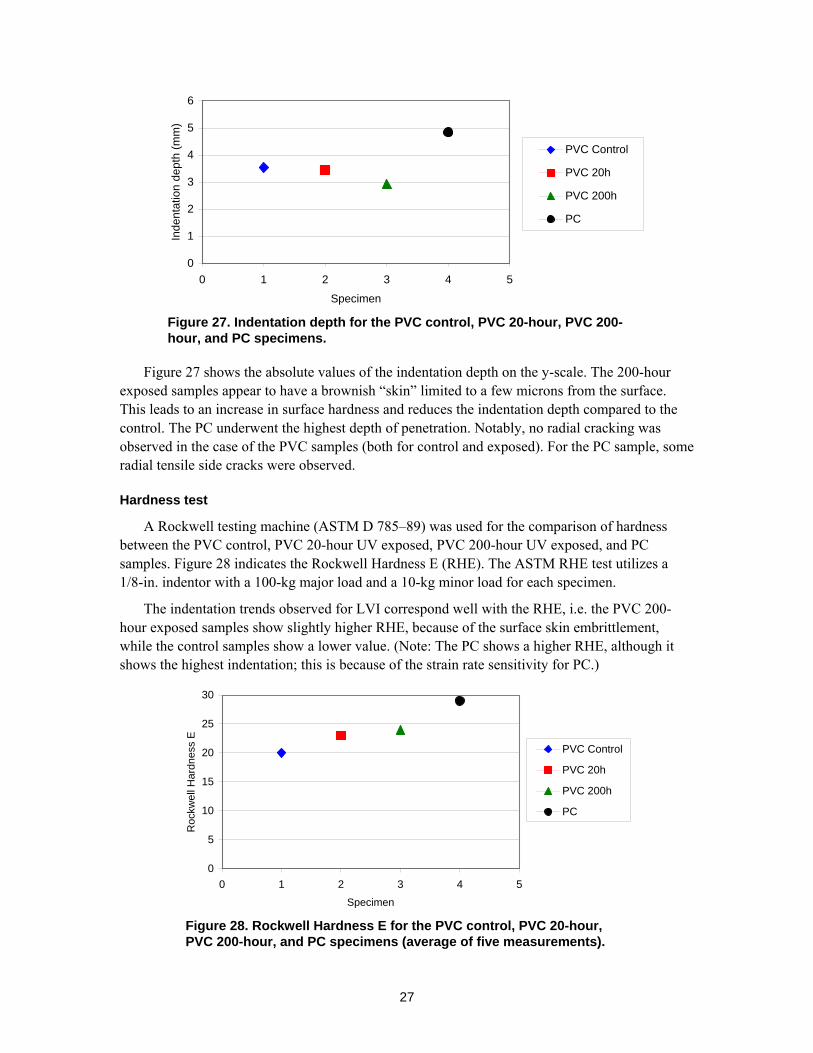
Figure 27. Indentation depth for the PVC control, PVC 20-hour, PVC 200-hour, and PC specimens.
Figure 27 shows the absolute values of the indentation depth on the y-scale. The 200-hour exposed samples appear to have a brownish “skin” limited to a few microns from the surface. This leads to an increase in surface hardness and reduces the indentation depth compared to the control. The PC underwent the highest depth of penetration. Notably, no radial cracking was observed in the case of the PVC samples (both for control and exposed). For the PC sample, some radial tensile side cracks were observed.
Hardness test
A Rockwell testing machine (ASTM D 785–89) was used for the comparison of hardness between the PVC control, PVC 20-hour UV exposed, PVC 200-hour UV exposed, and PC samples. Figure 28 indicates the Rockwell Hardness E (RHE). The ASTM RHE test utilizes a 1/8-in. indentor with a 100-kg major load and a 10-kg minor load for each specimen.
The indentation trends observed for LVI correspond well with the RHE, i.e. the PVC 200-hour exposed samples show slightly higher RHE, because of the surface skin embrittlement, while the control samples show a lower value. (Note: The PC shows a higher RHE, although it shows the highest indentation; this is because of the strain rate sensitivity for PC.)
0
5
10
15
20
25
30
0 1 2 3 4 5Specimen
Roc
kwel
l Har
dnes
s E
PVC Control
PVC 20h
PVC 200h
PC
Figure 28. Rockwell Hardness E for the PVC control, PVC 20-hour, PVC 200-hour, and PC specimens (average of five measurements).
28
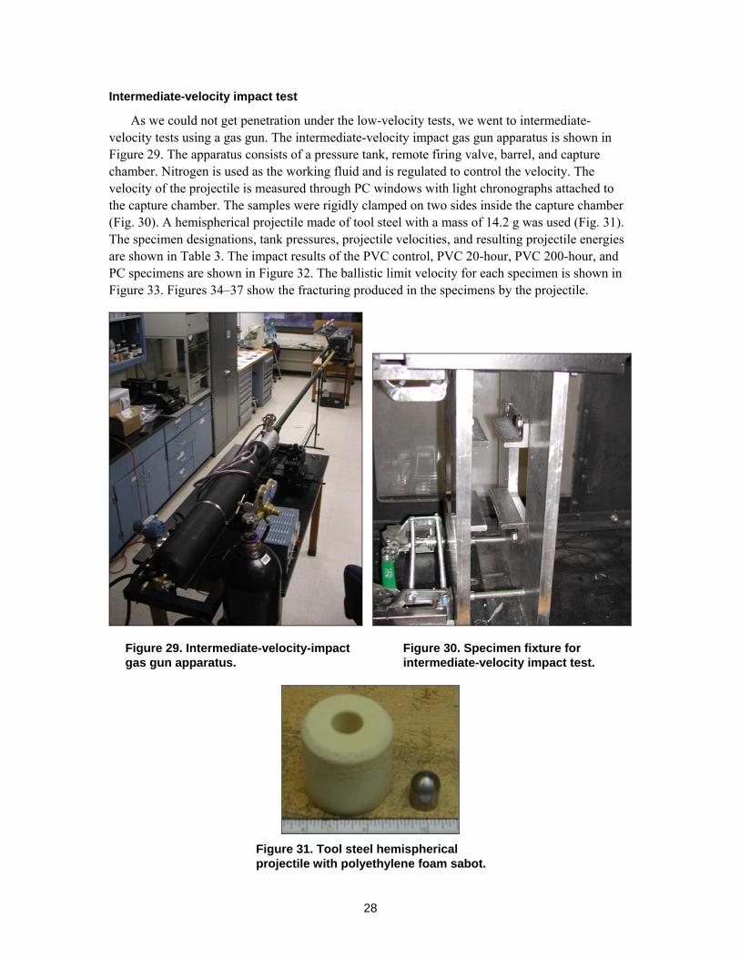
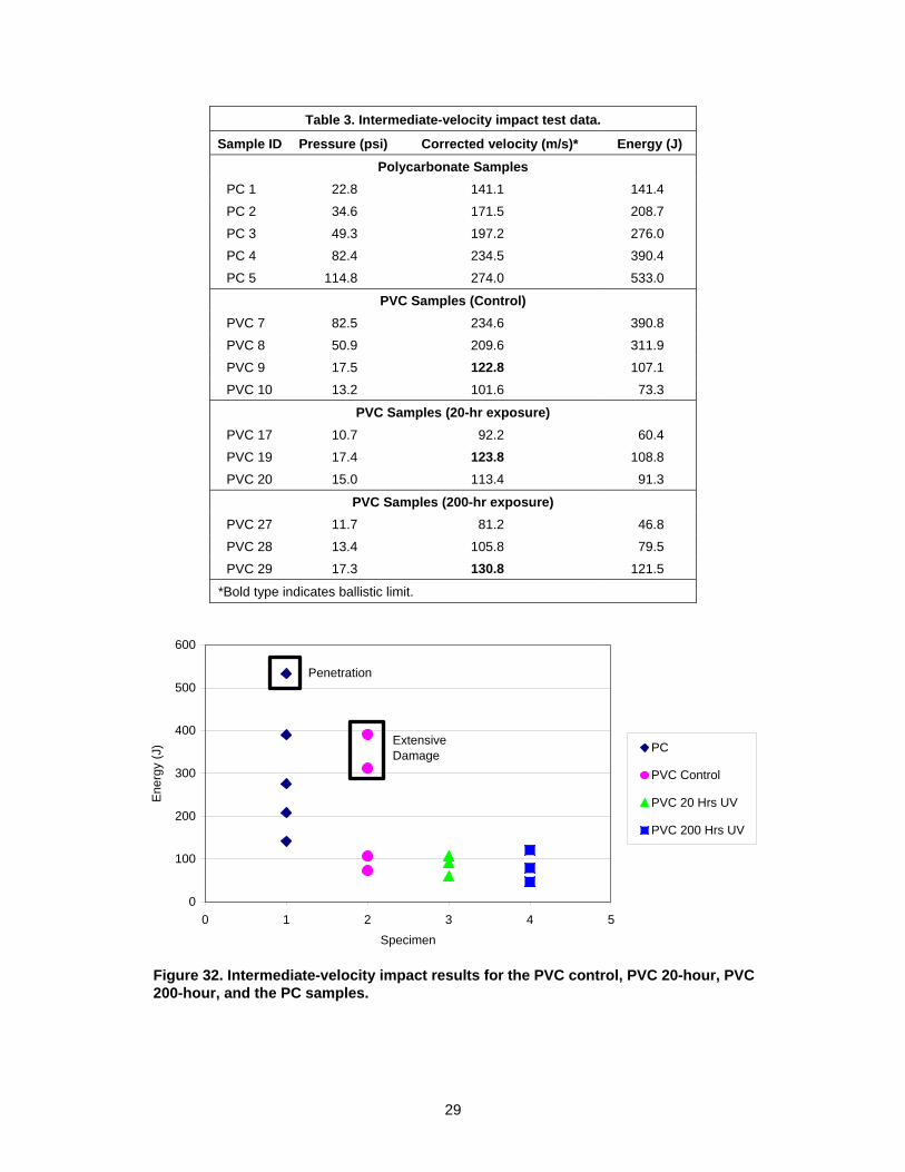
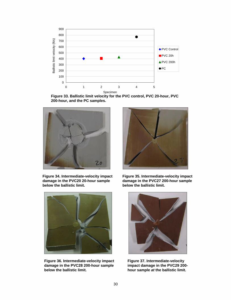
Intermediate-velocity impact test
As we could not get penetration under the low-velocity tests, we went to intermediate-velocity tests using a gas gun. The intermediate-velocity impact gas gun apparatus is shown in Figure 29. The apparatus consists of a pressure tank, remote firing valve, barrel, and capture chamber. Nitrogen is used as the working fluid and is regulated to control the velocity. The velocity of the projectile is measured through PC windows with light chronographs attached to the capture chamber. The samples were rigidly clamped on two sides inside the capture chamber (Fig. 30). A hemispherical projectile made of tool steel with a mass of 14.2 g was used (Fig. 31). The specimen designations, tank pressures, projectile velocities, and resulting projectile energies are shown in Table 3. The impact results of the PVC control, PVC 20-hour, PVC 200-hour, and PC specimens are shown in Figure 32. The ballistic limit velocity for each specimen is shown in Figure 33. Figures 34–37 show the fracturing produced in the specimens by the projectile.
Figure 29. Intermediate-velocity-impact gas gun apparatus.
Figure 30. Specimen fixture for intermediate-velocity impact test.
Figure 31. Tool steel hemispherical projectile with polyethylene foam sabot.
29
Table 3. Intermediate-velocity impact test data.
Sample ID Pressure (psi) Corrected velocity (m/s)* Energy (J) Polycarbonate Samples
PC 1 22.8 141.1 141.4
PC 2 34.6 171.5 208.7
PC 3 49.3 197.2 276.0
PC 4 82.4 234.5 390.4
PC 5 114.8 274.0 533.0
PVC Samples (Control) PVC 7 82.5 234.6 390.8
PVC 8 50.9 209.6 311.9
PVC 9 17.5 122.8 107.1
PVC 10 13.2 101.6 73.3
PVC Samples (20-hr exposure) PVC 17 10.7 92.2 60.4
PVC 19 17.4 123.8 108.8
PVC 20 15.0 113.4 91.3
PVC Samples (200-hr exposure) PVC 27 11.7 81.2 46.8
PVC 28 13.4 105.8 79.5
PVC 29 17.3 130.8 121.5
*Bold type indicates ballistic limit.
0
100
200
300
400
500
600
0 1 2 3 4 5Specimen
Ene
rgy
(J) PC
PVC Control
PVC 20 Hrs UV
PVC 200 Hrs UV
Penetration
Extensive Damage
Figure 32. Intermediate-velocity impact results for the PVC control, PVC 20-hour, PVC 200-hour, and the PC samples.
30
0
100
200
300
400
500
600
700
800
900
0 1 2 3 4 5
Specimen
Bal
listic
lim
it ve
loci
ty (f
t/s)
PVC Control
PVC 20h
PVC 200h
PC
Figure 33. Ballistic limit velocity for the PVC control, PVC 20-hour, PVC 200-hour, and the PC samples.
Figure 34. Intermediate-velocity impact damage in the PVC20 20-hour sample below the ballistic limit.
Figure 35. Intermediate-velocity impact damage in the PVC27 200-hour sample below the ballistic limit.
Figure 36. Intermediate-velocity impact damage in the PVC28 200-hour sample below the ballistic limit.
Figure 37. Intermediate-velocity impact damage in the PVC29 200-hour sample at the ballistic limit.
31
The PC samples show very localized damage and absorbed almost 500 J prior to penetration (ballistic velocity). All the PVC samples showed little or no indication of damage up to the threshold of ballistic penetration. The projectile simply bounced off, leaving a small indentation up to the ballistic limit. The ballistic limit was around 120 m/s, corresponding to approximately 120 J, at which multiple radial cracks were observed, as shown in the figure. The change in the effect of exposure as the ballistic limit increased slightly (from 122 to 130 m/s) can be attributed to the surface hardening of the 200-hour UV exposed samples.
To summarize, we have observed that:
• The UV exposure added a skin-like feature to a few microns of the surface of the PVC samples. The samples were quite thick, so the effect of exposure was minimal.
• There was severe discoloration of the samples after the 20-hour and 200-hour UV exposures.
• The low-velocity impact response was minimally influenced by the UV exposure. There was no radial cracking, and all PVC samples showed local indentation and a small bulge on the back face. The tests showed a peak load of about 25–30 kN and about 30 J of energy absorbed.
• The higher-velocity tests indicated that the PVC had a ballistic limit of 122–130 m/s, which caused radial cracks growing from the impact location. Up to 120 m/s, no indications of damage were seen; the projectile simply bounced off. The UV exposure increased the ballistic limit due to surface hardening.
32
6 IZOD IMPACT TESTS OF UV-EXPOSED PVC PLATES
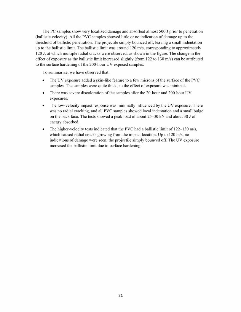
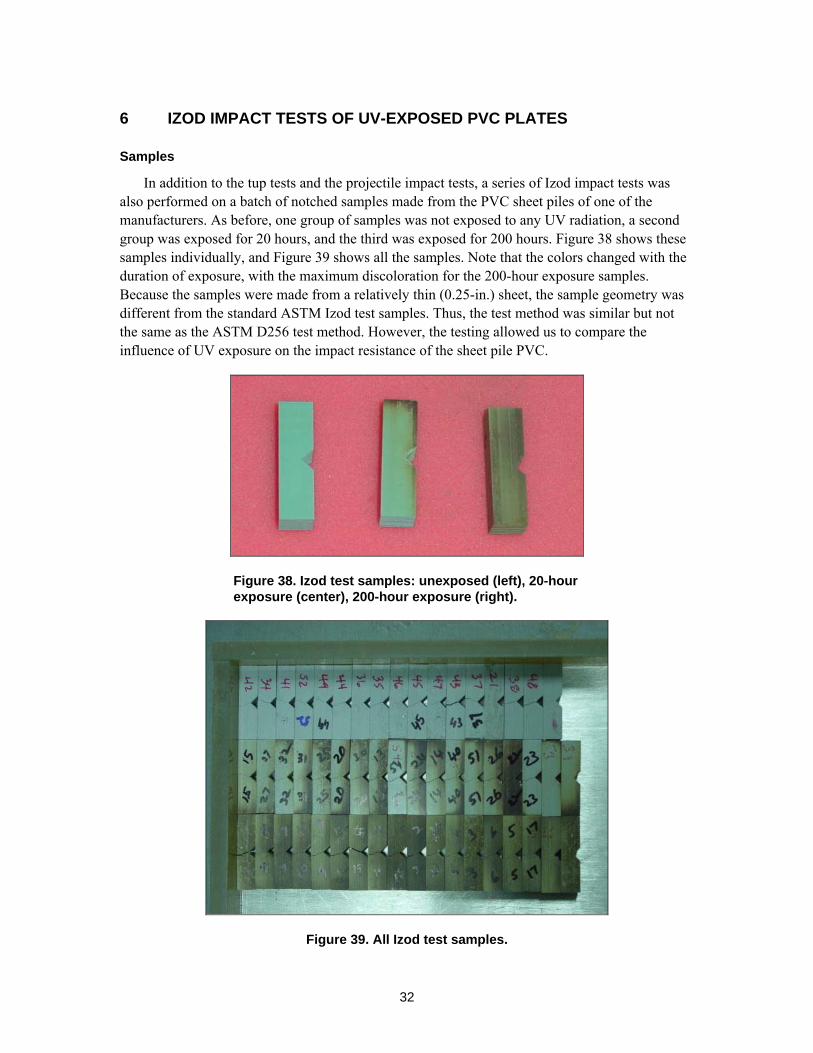
Samples
In addition to the tup tests and the projectile impact tests, a series of Izod impact tests was also performed on a batch of notched samples made from the PVC sheet piles of one of the manufacturers. As before, one group of samples was not exposed to any UV radiation, a second group was exposed for 20 hours, and the third was exposed for 200 hours. Figure 38 shows these samples individually, and Figure 39 shows all the samples. Note that the colors changed with the duration of exposure, with the maximum discoloration for the 200-hour exposure samples. Because the samples were made from a relatively thin (0.25-in.) sheet, the sample geometry was different from the standard ASTM Izod test samples. Thus, the test method was similar but not the same as the ASTM D256 test method. However, the testing allowed us to compare the influence of UV exposure on the impact resistance of the sheet pile PVC.
Figure 38. Izod test samples: unexposed (left), 20-hour exposure (center), 200-hour exposure (right).
Figure 39. All Izod test samples.
33
Izod test
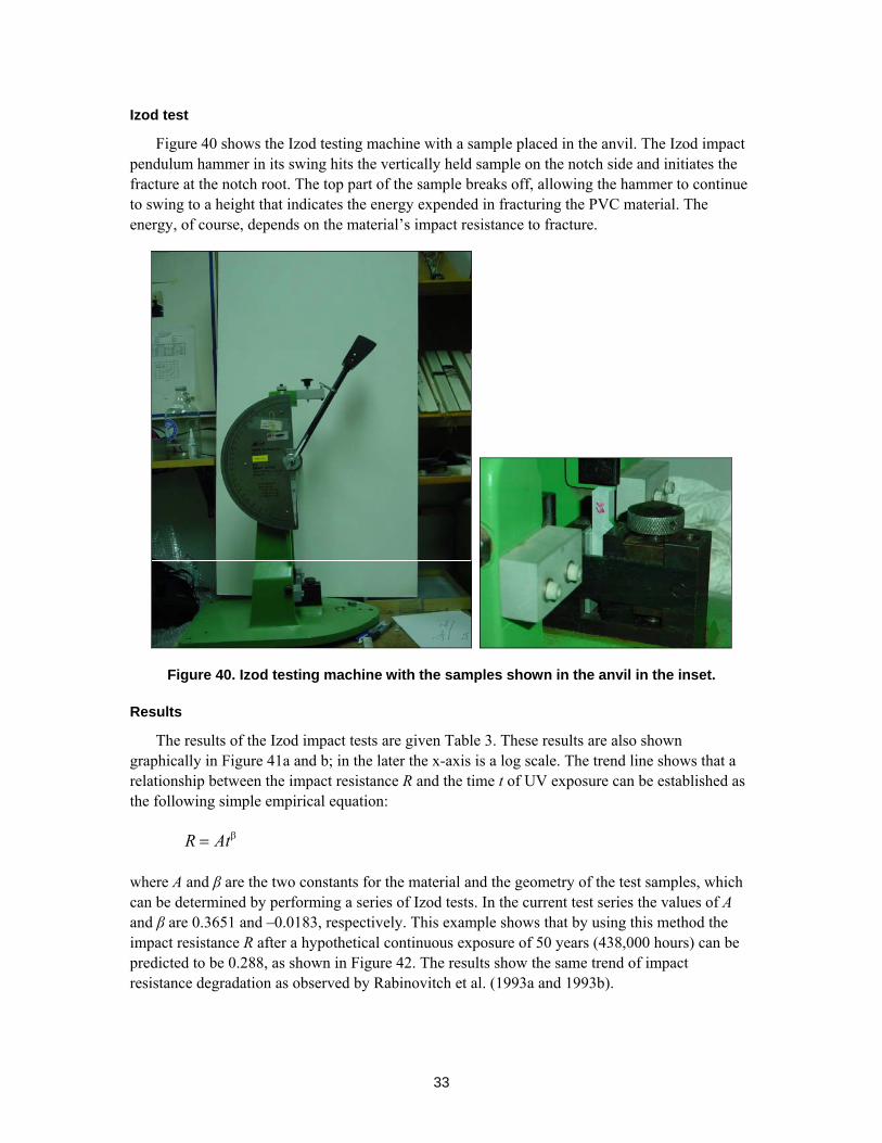
Figure 40 shows the Izod testing machine with a sample placed in the anvil. The Izod impact pendulum hammer in its swing hits the vertically held sample on the notch side and initiates the fracture at the notch root. The top part of the sample breaks off, allowing the hammer to continue to swing to a height that indicates the energy expended in fracturing the PVC material. The energy, of course, depends on the material’s impact resistance to fracture.
Figure 40. Izod testing machine with the samples shown in the anvil in the inset.
Results
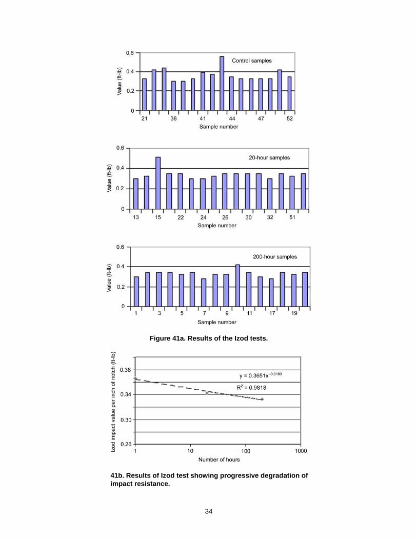
The results of the Izod impact tests are given Table 3. These results are also shown graphically in Figure 41a and b; in the later the x-axis is a log scale. The trend line shows that a relationship between the impact resistance R and the time t of UV exposure can be established as the following simple empirical equation:
R Atβ=
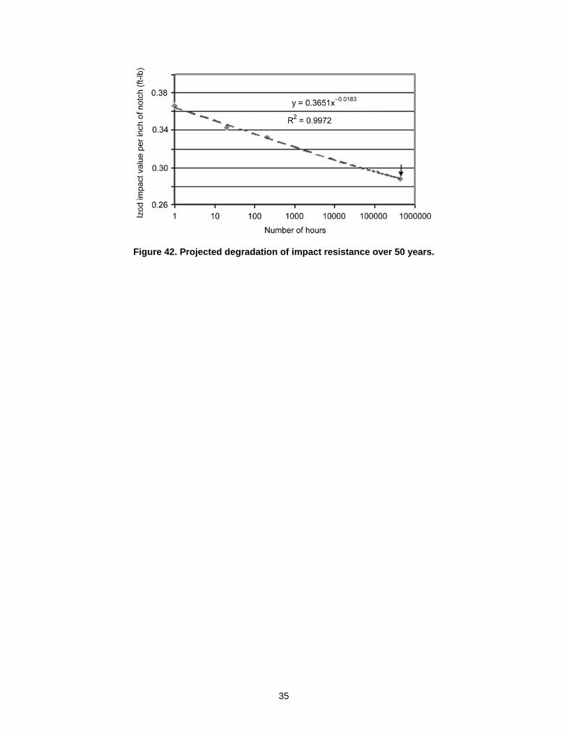
where A and β are the two constants for the material and the geometry of the test samples, which can be determined by performing a series of Izod tests. In the current test series the values of A and β are 0.3651 and –0.0183, respectively. This example shows that by using this method the impact resistance R after a hypothetical continuous exposure of 50 years (438,000 hours) can be predicted to be 0.288, as shown in Figure 42. The results show the same trend of impact resistance degradation as observed by Rabinovitch et al. (1993a and 1993b).
34
Figure 41a. Results of the Izod tests.
41b. Results of Izod test showing progressive degradation of impact resistance.
35
Figure 42. Projected degradation of impact resistance over 50 years.
36
7 ACCELERATED AGING TEST
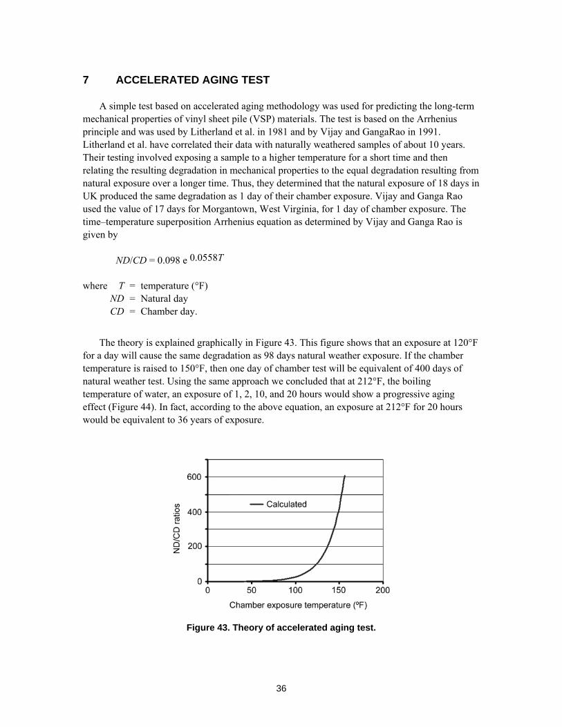
A simple test based on accelerated aging methodology was used for predicting the long-term mechanical properties of vinyl sheet pile (VSP) materials. The test is based on the Arrhenius principle and was used by Litherland et al. in 1981 and by Vijay and GangaRao in 1991. Litherland et al. have correlated their data with naturally weathered samples of about 10 years. Their testing involved exposing a sample to a higher temperature for a short time and then relating the resulting degradation in mechanical properties to the equal degradation resulting from natural exposure over a longer time. Thus, they determined that the natural exposure of 18 days in UK produced the same degradation as 1 day of their chamber exposure. Vijay and Ganga Rao used the value of 17 days for Morgantown, West Virginia, for 1 day of chamber exposure. The time–temperature superposition Arrhenius equation as determined by Vijay and Ganga Rao is given by
ND/CD = 0.098 e 0.0558T
where T = temperature (°F) ND = Natural day CD = Chamber day.
The theory is explained graphically in Figure 43. This figure shows that an exposure at 120°F for a day will cause the same degradation as 98 days natural weather exposure. If the chamber temperature is raised to 150°F, then one day of chamber test will be equivalent of 400 days of natural weather test. Using the same approach we concluded that at 212°F, the boiling temperature of water, an exposure of 1, 2, 10, and 20 hours would show a progressive aging effect (Figure 44). In fact, according to the above equation, an exposure at 212°F for 20 hours would be equivalent to 36 years of exposure.
Figure 43. Theory of accelerated aging test.
37
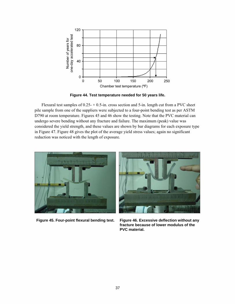
Figure 44. Test temperature needed for 50 years life.
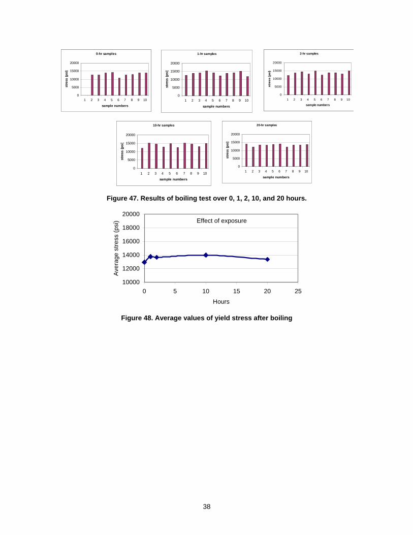
Flexural test samples of 0.25- × 0.5-in. cross section and 5-in. length cut from a PVC sheet pile sample from one of the suppliers were subjected to a four-point bending test as per ASTM D790 at room temperature. Figures 45 and 46 show the testing. Note that the PVC material can undergo severe bending without any fracture and failure. The maximum (peak) value was considered the yield strength, and these values are shown by bar diagrams for each exposure type in Figure 47. Figure 48 gives the plot of the average yield stress values; again no significant reduction was noticed with the length of exposure.
Figure 45. Four-point flexural bending test. Figure 46. Excessive deflection without any fracture because of lower modulus of the PVC material.
38
0-hr samples
0
5000
10000
15000
20000
1 2 3 4 5 6 7 8 9 10
sample numbers
stre
ss (p
si)
1-hr samples
0
5000
10000
15000
20000
1 2 3 4 5 6 7 8 9 10
sample numbers
stre
ss (p
si)
2-hr samples
0
5000
10000
15000
20000
1 2 3 4 5 6 7 8 9 10
sample numbers
stre
ss (p
si)
10-hr samples
0
5000
10000
15000
20000
1 2 3 4 5 6 7 8 9 10
sample numbers
stre
ss (p
si)
20-hr samples
0
5000
10000
15000
20000
1 2 3 4 5 6 7 8 9 10
sample numbers
stre
ss (p
si)
Figure 47. Results of boiling test over 0, 1, 2, 10, and 20 hours.
Effect of exposure
10000
12000
14000
16000
18000
20000
0 5 10 15 20 25
Hours
Ave
rage
stre
ss (p
si)
Figure 48. Average values of yield stress after boiling
39
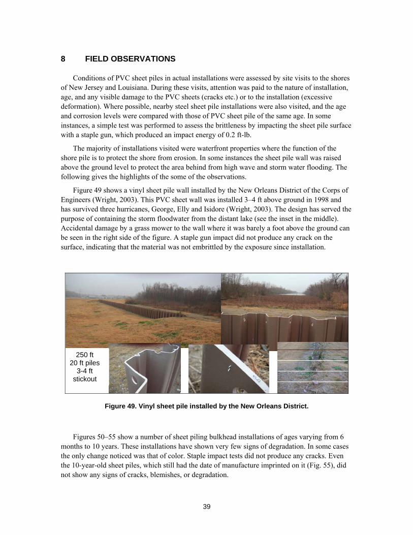
8 FIELD OBSERVATIONS
Conditions of PVC sheet piles in actual installations were assessed by site visits to the shores of New Jersey and Louisiana. During these visits, attention was paid to the nature of installation, age, and any visible damage to the PVC sheets (cracks etc.) or to the installation (excessive deformation). Where possible, nearby steel sheet pile installations were also visited, and the age and corrosion levels were compared with those of PVC sheet pile of the same age. In some instances, a simple test was performed to assess the brittleness by impacting the sheet pile surface with a staple gun, which produced an impact energy of 0.2 ft-lb.
The majority of installations visited were waterfront properties where the function of the shore pile is to protect the shore from erosion. In some instances the sheet pile wall was raised above the ground level to protect the area behind from high wave and storm water flooding. The following gives the highlights of the some of the observations.
Figure 49 shows a vinyl sheet pile wall installed by the New Orleans District of the Corps of Engineers (Wright, 2003). This PVC sheet wall was installed 3–4 ft above ground in 1998 and has survived three hurricanes, George, Elly and Isidore (Wright, 2003). The design has served the purpose of containing the storm floodwater from the distant lake (see the inset in the middle). Accidental damage by a grass mower to the wall where it was barely a foot above the ground can be seen in the right side of the figure. A staple gun impact did not produce any crack on the surface, indicating that the material was not embrittled by the exposure since installation.
250 ft 20 ft piles
3-4 ft stickout
Figure 49. Vinyl sheet pile installed by the New Orleans District.
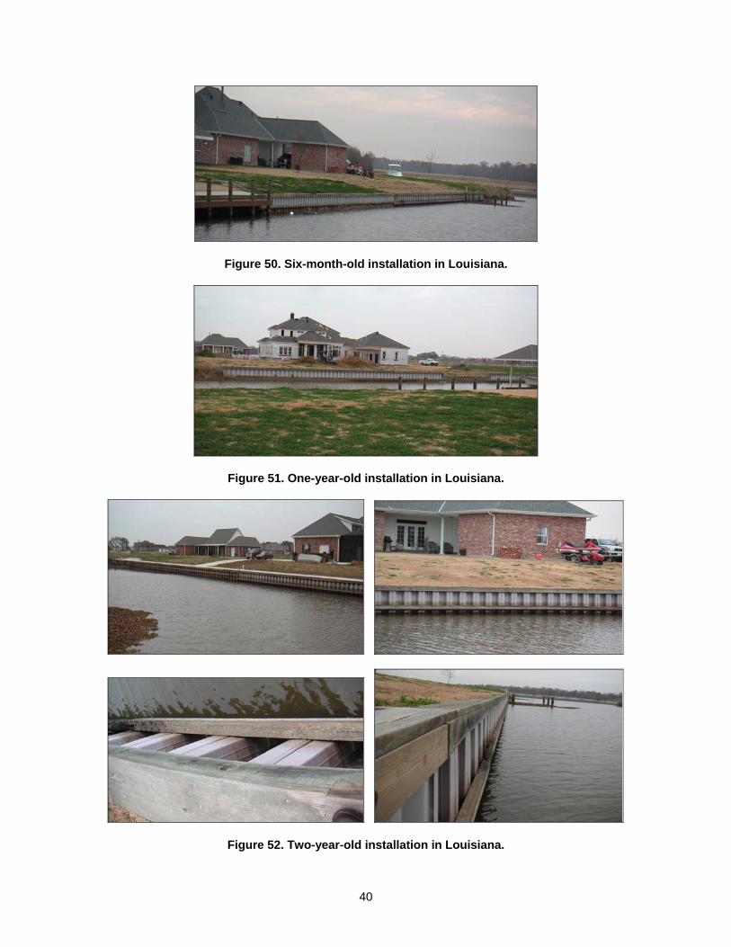
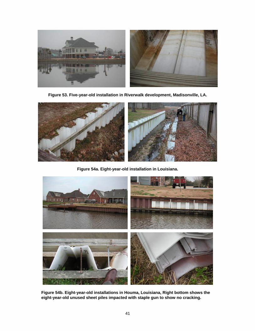
Figures 50–55 show a number of sheet piling bulkhead installations of ages varying from 6 months to 10 years. These installations have shown very few signs of degradation. In some cases the only change noticed was that of color. Staple impact tests did not produce any cracks. Even the 10-year-old sheet piles, which still had the date of manufacture imprinted on it (Fig. 55), did not show any signs of cracks, blemishes, or degradation.
40
Figure 50. Six-month-old installation in Louisiana.
Figure 51. One-year-old installation in Louisiana.
Figure 52. Two-year-old installation in Louisiana.
41
Figure 53. Five-year-old installation in Riverwalk development, Madisonville, LA.
Figure 54a. Eight-year-old installation in Louisiana.
Figure 54b. Eight-year-old installations in Houma, Louisiana, Right bottom shows the eight-year-old unused sheet piles impacted with staple gun to show no cracking.
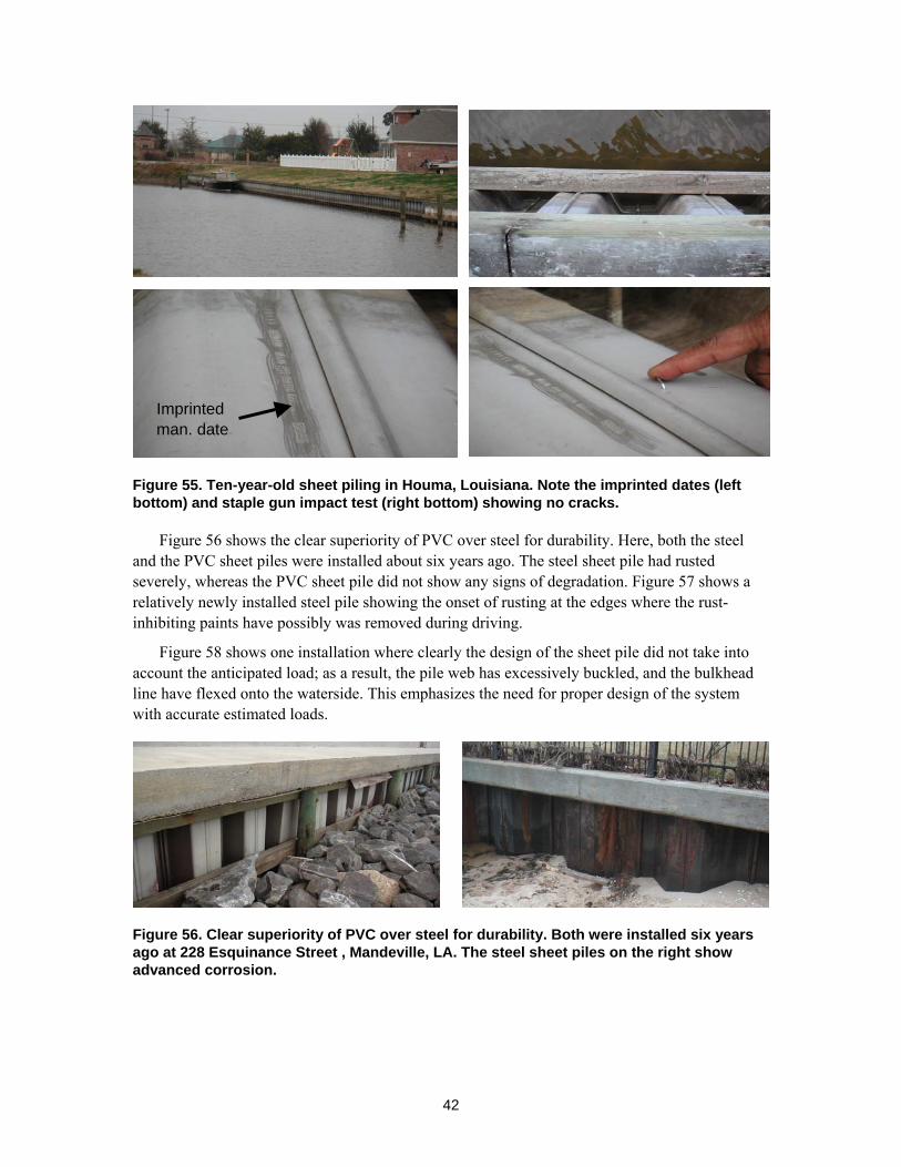
42
Figure 55. Ten-year-old sheet piling in Houma, Louisiana. Note the imprinted dates (left bottom) and staple gun impact test (right bottom) showing no cracks.
Figure 56 shows the clear superiority of PVC over steel for durability. Here, both the steel and the PVC sheet piles were installed about six years ago. The steel sheet pile had rusted severely, whereas the PVC sheet pile did not show any signs of degradation. Figure 57 shows a relatively newly installed steel pile showing the onset of rusting at the edges where the rust-inhibiting paints have possibly was removed during driving.
Figure 58 shows one installation where clearly the design of the sheet pile did not take into account the anticipated load; as a result, the pile web has excessively buckled, and the bulkhead line have flexed onto the waterside. This emphasizes the need for proper design of the system with accurate estimated loads.
Figure 56. Clear superiority of PVC over steel for durability. Both were installed six years ago at 228 Esquinance Street , Mandeville, LA. The steel sheet piles on the right show advanced corrosion.
Imprinted man. date
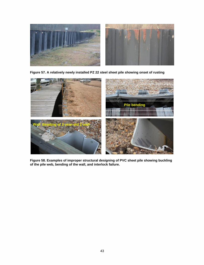
43
Figure 57. A relatively newly installed PZ 22 steel sheet pile showing onset of rusting
Pile bending
Wall Bending of 2-year-old Z-wall
Figure 58. Examples of improper structural designing of PVC sheet pile showing buckling of the pile web, bending of the wall, and interlock failure.
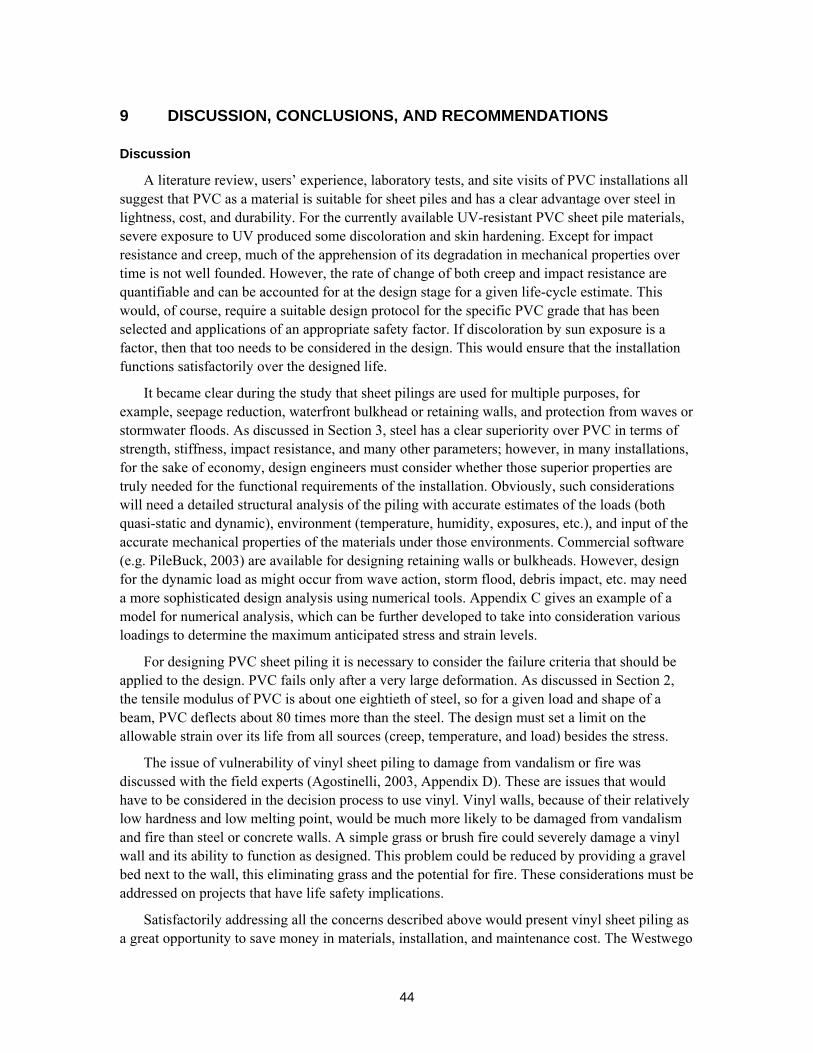
44
9 DISCUSSION, CONCLUSIONS, AND RECOMMENDATIONS
Discussion
A literature review, users’ experience, laboratory tests, and site visits of PVC installations all suggest that PVC as a material is suitable for sheet piles and has a clear advantage over steel in lightness, cost, and durability. For the currently available UV-resistant PVC sheet pile materials, severe exposure to UV produced some discoloration and skin hardening. Except for impact resistance and creep, much of the apprehension of its degradation in mechanical properties over time is not well founded. However, the rate of change of both creep and impact resistance are quantifiable and can be accounted for at the design stage for a given life-cycle estimate. This would, of course, require a suitable design protocol for the specific PVC grade that has been selected and applications of an appropriate safety factor. If discoloration by sun exposure is a factor, then that too needs to be considered in the design. This would ensure that the installation functions satisfactorily over the designed life.
It became clear during the study that sheet pilings are used for multiple purposes, for example, seepage reduction, waterfront bulkhead or retaining walls, and protection from waves or stormwater floods. As discussed in Section 3, steel has a clear superiority over PVC in terms of strength, stiffness, impact resistance, and many other parameters; however, in many installations, for the sake of economy, design engineers must consider whether those superior properties are truly needed for the functional requirements of the installation. Obviously, such considerations will need a detailed structural analysis of the piling with accurate estimates of the loads (both quasi-static and dynamic), environment (temperature, humidity, exposures, etc.), and input of the accurate mechanical properties of the materials under those environments. Commercial software (e.g. PileBuck, 2003) are available for designing retaining walls or bulkheads. However, design for the dynamic load as might occur from wave action, storm flood, debris impact, etc. may need a more sophisticated design analysis using numerical tools. Appendix C gives an example of a model for numerical analysis, which can be further developed to take into consideration various loadings to determine the maximum anticipated stress and strain levels.
For designing PVC sheet piling it is necessary to consider the failure criteria that should be applied to the design. PVC fails only after a very large deformation. As discussed in Section 2, the tensile modulus of PVC is about one eightieth of steel, so for a given load and shape of a beam, PVC deflects about 80 times more than the steel. The design must set a limit on the allowable strain over its life from all sources (creep, temperature, and load) besides the stress.
The issue of vulnerability of vinyl sheet piling to damage from vandalism or fire was discussed with the field experts (Agostinelli, 2003, Appendix D). These are issues that would have to be considered in the decision process to use vinyl. Vinyl walls, because of their relatively low hardness and low melting point, would be much more likely to be damaged from vandalism and fire than steel or concrete walls. A simple grass or brush fire could severely damage a vinyl wall and its ability to function as designed. This problem could be reduced by providing a gravel bed next to the wall, this eliminating grass and the potential for fire. These considerations must be addressed on projects that have life safety implications.
Satisfactorily addressing all the concerns described above would present vinyl sheet piling as a great opportunity to save money in materials, installation, and maintenance cost. The Westwego
45
canal hurricane protection wall, installed by the Corps of Engineers (Wright, 2003), is a good example of such accomplishment. Since its installation in 1998, it has survived three hurricanes and five years of weathering without any visible structural damage, despite the accumulation of a foot of flood-deposited sediments at the toe. A photograph of the wall shown in Figure 49 clearly shows the verticality and alignment still well maintained. The only damage that occurred was the accidental destruction of a foot of stickout in the high ground.
Conclusions
• Field inspection showed no significant degradation even in ten-year-old sheet piles • Published research has shown that in five years of weathering very little degradation
happened in tensile strength and a slight improvement occurred in the flexural properties. However, impact properties degraded with time.
• The basic material, PVC, is well investigated, and exhaustive data are available from organizations like Vinyl Institute, Vinyl by Design, etc
• Corrosion degradation of steel pile was observed to be much faster than any degradation of PVC sheet pile.
• The four U.S. manufacturers of PVC sheet piles have different design approaches in structuring the materials and profiling the shapes of the PVC sheet piles.
• No ASTM standards or other standards were found to assess the performance of PVC sheet piles.
• Laboratory accelerated aging studies showed insignificant degradation in flexural properties with aging.
• UV exposure may cause discoloration after prolonged exposure. • UV exposure reduces notched impact strength, but the reduction rate can be quantified. • UV exposure tends to harden the surface. As a result, flexural properties tend to improve.
It provides better penetration resistance under low- and high-velocity projectile impacts
Recommendations
• A solid design approach based on well-defined functional requirements needs to be developed.
• Functional requirements in addition to maintenance of long-term integrity must also include the degrees of expected resistance to various hazards, such as accidental overload, fire, impact, vandalism, etc.
• Functional requirements should also take into consideration the special maintenance requirements (such as frequent inspections, replacing damaged sheets, maintaining grass-free footing, etc.) that may be necessary for using non-metallic sheet piling.
• Life safety and other risks can be addressed by including them in the functional requirements. The design must address the installation and maintenance requirements.
• Manufacturers need to certify material specifications based on standardized testing conducted by independent test labs.
46
• Cost-effective non-metallic PVC sheet pile is under development using thermoplastic fiber-reinforced composites that may meet the strength, stiffness, lightness, creep, fatigue, impact, and durability requirements and provide another alternative to steel sheet piling. This sheet piling in the future should satisfy both deflection and strength criteria for failure.
• Both PVC and polymer composite sheet piles may suffer abrasion and thickness reduction by coarse sand or other debris rubbing against the sheet pile over time. Special protective coatings or design may be required where such problems are present.
47
REFERENCES
ASTM D256, Standard Test Methods for Determining the Pendulum Impact Resistance of Notched Specimens of Plastics.
ASTM D785, Standard Test Method for Rockwell Hardness of Plastics and Electrical Insulating Materials.
ASTM D790, Standard Test Methods for Flexural Properties of Unreinforced and Reinforced plastics and Electrical Insulating Materials.
ASTM D1435, Standard Practice for Outdoor Weathering of Plastics.
ASTM D4226, Standard Test Methods for Impact Resistance of Rigid Poly(Vinyl Chloride) (PVC) Building Products.
Corus, C.P. (2001) Piling Handbook, Internet Edition.
Lampo, R., Nosker, T., Barno, D., Busel, J., Maher, A., Dutta, P., and Odello, R. (1998) Development and Demonstration of FRP Composite Fender, Load Bearing, and Sheet Piling Systems, USA-CERL Technical Report 98/123, Construction Productivity Advancement Research (CPAR) Program.
Litherland, K.L. Oakley, D.R., and Proctor, B.A. (1981) The Use of Accelerated Aging Procedures to Predict the Long Term Strength of GRC Composites. Cement and Concrete Research, Vol. 11, p. 455–466.
Materials International (2002) Engineering Considerations.
Northstar (2001) Northstar Final Report 10,000-Hour Unconfined Tension Creep Testing Northstar Vinyl Sheet Piles 1900 and 9400 Series. Prepared by SGI Testing Services, LLC, Project Number SGI1035, 26 July 2001.
Polymer Diagnostics, Inc. (1998) Model for the Prediction of Time and Temperature Dependent Modulus of SU17A-1. Report prepared for Crane Plastics Company, January 9, 1998, http://www.polymerdiagnostics.com.
Polymer Diagnostics, Inc.(1998) Model for the Prediction of Time and Temperature Dependent Modulus of SU17A-1. Report to Crane Plastics.
Rabinovitch, E.B., Summers, J.W., and Northcott, W.E. (1993) Changes in Properties of Rigid PVC During Weathering. INTEC Conference Proceedings, p. 1784–1787.
Rabinovitch, E.B., Summers, J.W., and Northcott, W.E. (1993) Changes in Properties of Rigid PVC During Weathering. Journal of Vinyl Technology, December 1993, Vol. 15, No. 4.
Summers, J.W., and Rabinovitch, E.B. (1999) Weatherability of Vinyl and Other Plastics, Weathering of Plastics (G. Wyoych, Ed.). Plastics Design Library, NY, p. 61–68.
Tom, J.G, and Tom, J.C. (2002) CMB Report 02-008: Results of Vinyl Sheet Pile Materials Investigation of New Orleans District, March 2002, U.S. Army Corps of Engineers ERDC-GSL.
U.S. Army Corps of Engineers (1994) Design of Sheet Pile Walls. EM 1110-2-2504, 31 Mar 94.
Vinyl Institute (2003) http://www.vinylinfo.org/materialvinyl/material.html.

48
Vinyl by Design (2003) http://www.vinylbydesign.com/
Vijay, P.V., and GangaRao, H.V.S. (1991) Accelerated and Natural Weathering of Glass Fiber Reinforced Plastic Bars. ACI International, Fourth International Symposium Fiber Reinforced Polymer Reinforcement for Reinforced Concrete Structures, SP-188.
Wright, T.W. (2003) Technical communication and response to questionnaire.
The lower arrow shows
49
APPENDIX A: QUESTIONNAIRE FOR THE MANUFACTURER’S DATA
Study of Vinyl Sheet Piles for Long-term Applications
(Responses are requested to be sent by electronic mail to [email protected])
1. General: Name, address, tel no. fax no. e-mail address and website (if any) of the company.
2. Products: Commercial names/model nos. of the vinyl sheet pile products.
3. Raw materials for the vinyl sheet piles:
3.1 Please specify the PVC used is recycled/post industrial/or virgin
3.2 Any standards to which the raw material conforms, and how it is ensured.
3.3 If your company to ensure the quality and specifications of the raw materials performs any tests please give details.
4. Manufacturing Process:
4.1 Describe the process for manufacturing the vinyl sheet piles from the raw materials.
4.2 Do you add any additives during the processing to manufacture the sheet piles.
4.3 If you add any additives do they modify the properties of the final physical and mechanical properties of the PVC in the sheet pile any way. If so, what modifications do you get.
5. Testing of Products:
What testing, if any, you perform on the manufactured sheet piles to make the products conform to the declared specifications of your products. Please mention if those tests conform to any ASTM or any other nationally recognized tests.
6. Specifications:
Please give the physical and mechanical specifications of each of your vinyl sheet pile products.
7. Historic Data
7.1 Date when was the first time your PVC sheet pile product marketed and then installed.
7.2 Have you changed the raw materials, composition including additives, manufacturing process since the start time. If so, please comment on the changes.
7.3 Can you share the installation data of at least three of your old vinyl sheet piles installations. If yes, please give the following:
7.3.1 Date of manufacture
7.3.2 Date of installation
7.3.3 Address of the installation
7.3.4 Names and Specifications of the products installed.
7.3.5 Functional requirements of the installation
50
7.3.6 Driving method used
7.3.7 Length of the installation
7.3.8 Depth inside ground
7.3.9 Depth inside water
7.3.10 Exposed length above water.
7.3.11 Do you know of any problems with this installation, for example
Excessive deformation/flexure
cracks
Interlock failure
Any other
8. Life Cycle
8.1 What is the expected life cycle of your product under normal use.
8.2 Have you performed any test to establish this life cycle.
8.3 Do you have any data to establish this life cycle without test.
9. Degradation of properties over time:
9.1 Strengths:
Have you established any change with time in compressive strength, tensile strength and shear strength of the material constituting your vinyl sheet pile products by exposure to out door conditions (sunlight). If so, what is the rate of change?
9.2 Elastic modulus:
The value of elastic modulus controls the stiffness or deflection of the installed sheet piles. Have you established any change with time of the elastic modulus of the material constituting your vinyl sheet pile products by exposure to out door conditions (sunlight). If so, what is the rate of change?
9.3 Creep:
Thermoplastic polymers are known to creep under a sustained stress. Have you established the creep rate for the final polymer mix that constitutes the material of your vinyl sheet pile products? If so, what it is.
9.4 Impact Resistance:
Have you established any change with time the impact resistance of the material constituting your vinyl sheet pile products by exposure to out door conditions (sunlight). If so, what is the rate of change?
10. Any other information you consider pertinent to these studies.
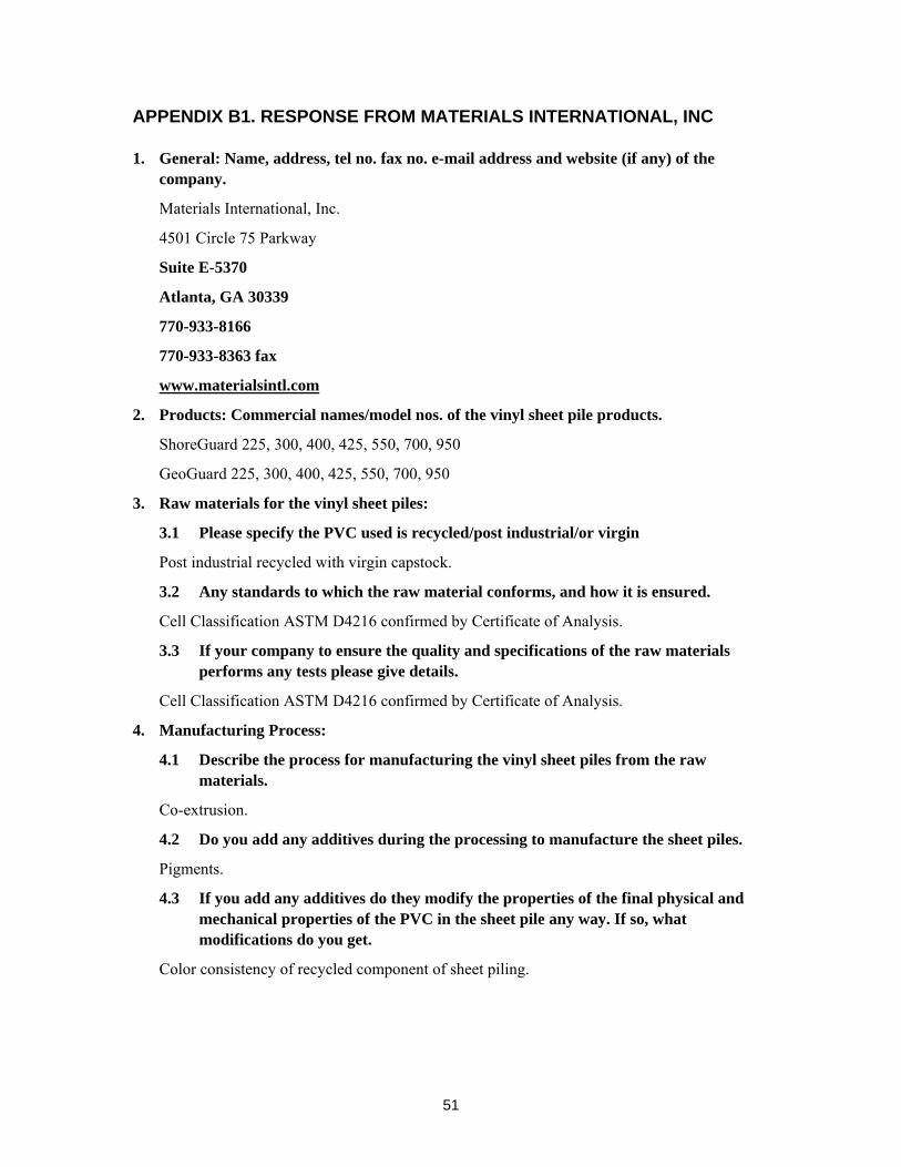
51
APPENDIX B1. RESPONSE FROM MATERIALS INTERNATIONAL, INC
1. General: Name, address, tel no. fax no. e-mail address and website (if any) of the company.
Materials International, Inc.
4501 Circle 75 Parkway
Suite E-5370
Atlanta, GA 30339
770-933-8166
770-933-8363 fax
www.materialsintl.com
2. Products: Commercial names/model nos. of the vinyl sheet pile products.
ShoreGuard 225, 300, 400, 425, 550, 700, 950
GeoGuard 225, 300, 400, 425, 550, 700, 950
3. Raw materials for the vinyl sheet piles:
3.1 Please specify the PVC used is recycled/post industrial/or virgin
Post industrial recycled with virgin capstock.
3.2 Any standards to which the raw material conforms, and how it is ensured.
Cell Classification ASTM D4216 confirmed by Certificate of Analysis.
3.3 If your company to ensure the quality and specifications of the raw materials performs any tests please give details.
Cell Classification ASTM D4216 confirmed by Certificate of Analysis.
4. Manufacturing Process:
4.1 Describe the process for manufacturing the vinyl sheet piles from the raw materials.
Co-extrusion.
4.2 Do you add any additives during the processing to manufacture the sheet piles.
Pigments.
4.3 If you add any additives do they modify the properties of the final physical and mechanical properties of the PVC in the sheet pile any way. If so, what modifications do you get.
Color consistency of recycled component of sheet piling.
52
5. Testing of Products:
What testing, if any, you perform on the manufactured sheet piles to make the products conform to the declared specifications of your products. Please mention if those tests conform to any ASTM or any other nationally recognized tests.
Bench Testing
Field Testing
Quality Control Testing
ASTM D4216
ASTM D4226
ASTM D256
ASTM D638
ASTM D790
ASTM D1435
6. Specifications:
Please give the physical and mechanical specifications of each of your vinyl sheet pile products.
See attached ShoreGuard Specifications Chart.
7. Historic Data
7.1 Date when was the first time your PVC sheet pile product marketed and then installed.
1989
7.2 Have you changed the raw materials, composition including additives, manufacturing process since the start time. If so, please comment on the changes.
Original products were extruded entirely out of virgin vinyl. When recycled vinyl was incorporated, the sheet piling were co-extruded with virgin capstock.
Vinyl suppliers continue to improve the formulations on a regular basis.
7.3 Can you share the installation data of at least three of your old vinyl sheet piles installations. If yes, please give the following:
To be addressed during field evaluation in late January. 7.3.1 Date of manufacture
7.3.2 Date of installation
7.3.3 Address of the installation
7.3.4 Names and Specifications of the products installed.
7.3.5 Functional requirements of the installation
7.3.6 Driving method used
53
7.3.7 Length of the installation
7.3.8 Depth inside ground
7.3.9 Depth inside water
7.3.10 Exposed length above water.
7.3.11 Do you know of any problems with this installation, for example
Excessive deformation/flexure
cracks
Interlock failure
Any other
8. Life Cycle
8.1 What is the expected life cycle of your product under normal use.
Plastics Industry product life expectancy of 50+ years.
8.2 Have you performed any test to establish this life cycle.
Millions of square feet of product in use in excess of 10+ years.
8.3 Do you have any data to establish this life cycle without test.
Millions of square feet of product in use in excess of 10+ years.
9. Degradation of properties over time:
9.1 Strengths:
Have you established any change with time in compressive strength, tensile strength and shear strength of the material constituting your vinyl sheet pile products by exposure to out door conditions (sunlight). If so, what is the rate of change?
Physical properties of Flexural Strength, Flexural Modulus, Tensile Strength, and Tensile Modulus remain relatively constant over time. Long-term outdoor weathering studies show 60 percent impact retention in high UV climates.
9.2 Elastic modulus:
The value of elastic modulus controls the stiffness or deflection of the installed sheet piles. Have you established any change with time of the elastic modulus of the material constituting your vinyl sheet pile products by exposure to out door conditions (sunlight). If so, what is the rate of change?
Physical properties of Flexural Strength, Flexural Modulus, Tensile Strength, and Tensile Modulus remain relatively constant over time.
9.3 Creep:
Thermoplastic polymers are known to creep under a sustained stress. Have you established the creep rate for the final polymer mix that constitutes the material of your vinyl sheet pile products? If so, what it is.
54
Creep precluded when stress is under 3,200 psi.
9.4 Impact Resistance:
Have you established any change with time the impact resistance of the material constituting your vinyl sheet pile products by exposure to out door conditions (sunlight). If so, what is the rate of change?
Long-term outdoor weathering studies show 60 percent impact retention in high UV climates.
10. Any other information you consider pertinent to these studies.
March 27, 2002 Report to Wade Wright, COE
July 19, 2002 Report to Carl Guggenheimer, COE
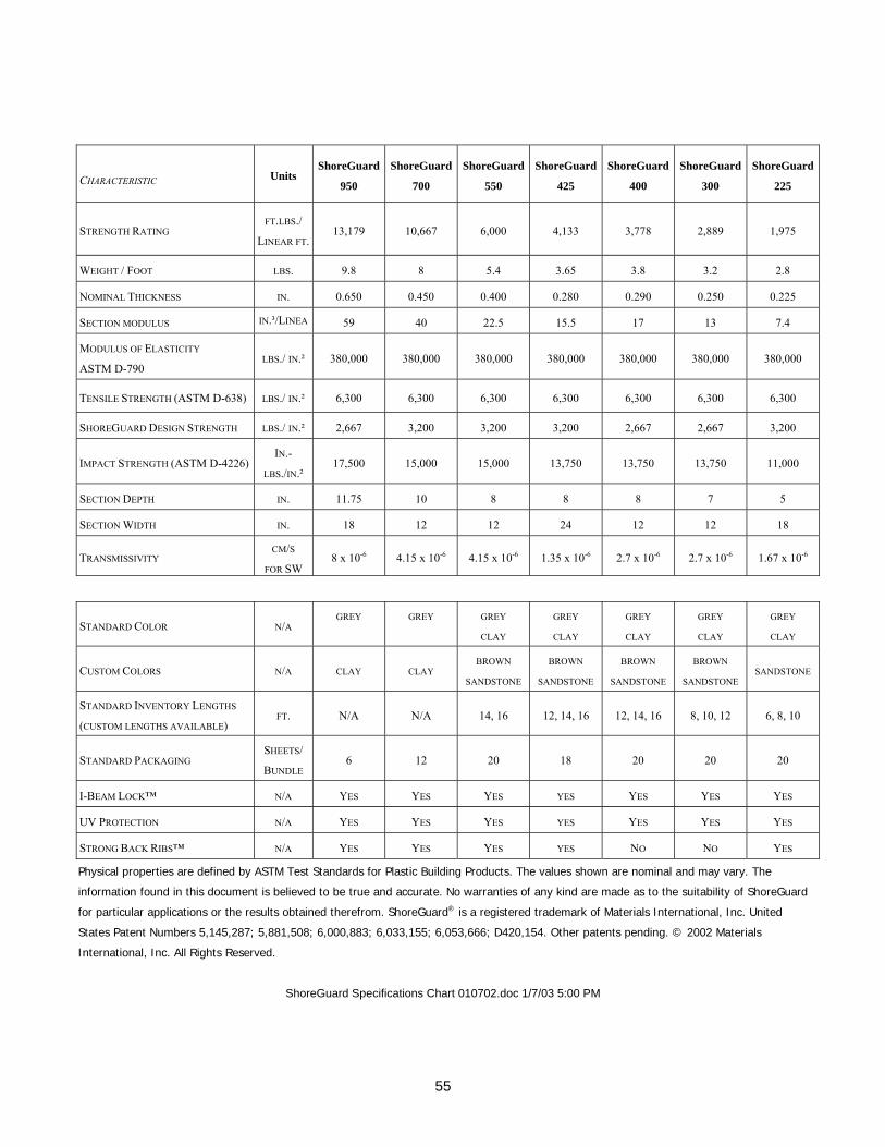
55
CHARACTERISTIC Units ShoreGuard
950
ShoreGuard
700
ShoreGuard
550
ShoreGuard
425
ShoreGuard
400
ShoreGuard
300
ShoreGuard
225
STRENGTH RATING FT.LBS./
LINEAR FT. 13,179 10,667 6,000 4,133 3,778 2,889 1,975
WEIGHT / FOOT LBS. 9.8 8 5.4 3.65 3.8 3.2 2.8
NOMINAL THICKNESS IN. 0.650 0.450 0.400 0.280 0.290 0.250 0.225
SECTION MODULUS IN.³/LINEA 59 40 22.5 15.5 17 13 7.4
MODULUS OF ELASTICITY
ASTM D-790 LBS./ IN.² 380,000 380,000 380,000 380,000 380,000 380,000 380,000
TENSILE STRENGTH (ASTM D-638) LBS./ IN.² 6,300 6,300 6,300 6,300 6,300 6,300 6,300
SHOREGUARD DESIGN STRENGTH LBS./ IN.² 2,667 3,200 3,200 3,200 2,667 2,667 3,200
IMPACT STRENGTH (ASTM D-4226) IN.-
LBS./IN.² 17,500 15,000 15,000 13,750 13,750 13,750 11,000
SECTION DEPTH IN. 11.75 10 8 8 8 7 5
SECTION WIDTH IN. 18 12 12 24 12 12 18
TRANSMISSIVITY CM/S
FOR SW 8 x 10⁻⁶ 4.15 x 10⁻⁶ 4.15 x 10⁻⁶ 1.35 x 10⁻⁶ 2.7 x 10⁻⁶ 2.7 x 10⁻⁶ 1.67 x 10⁻⁶
STANDARD COLOR N/A GREY
GREY
GREY
CLAY
GREY
CLAY
GREY
CLAY
GREY
CLAY
GREY
CLAY
CUSTOM COLORS N/A CLAY CLAY BROWN
SANDSTONE
BROWN
SANDSTONE
BROWN
SANDSTONE
BROWN
SANDSTONE SANDSTONE
STANDARD INVENTORY LENGTHS
(CUSTOM LENGTHS AVAILABLE) FT. N/A N/A 14, 16 12, 14, 16 12, 14, 16 8, 10, 12 6, 8, 10
STANDARD PACKAGING SHEETS/
BUNDLE 6 12 20 18 20 20 20
I-BEAM LOCK™ N/A YES YES YES YES YES YES YES
UV PROTECTION N/A YES YES YES YES YES YES YES
STRONG BACK RIBS™ N/A YES YES YES YES NO NO YES
Physical properties are defined by ASTM Test Standards for Plastic Building Products. The values shown are nominal and may vary. The
information found in this document is believed to be true and accurate. No warranties of any kind are made as to the suitability of ShoreGuard
for particular applications or the results obtained therefrom. ShoreGuard® is a registered trademark of Materials International, Inc. United
States Patent Numbers 5,145,287; 5,881,508; 6,000,883; 6,033,155; 6,053,666; D420,154. Other patents pending. © 2002 Materials
International, Inc. All Rights Reserved.
ShoreGuard Specifications Chart 010702.doc 1/7/03 5:00 PM
56
APPENDIX B2. RESPONSE FROM CRANE PRODUCTS LTD
1. General: Name, address, tel no. fax no. e-mail address and website (if any) of the company.
Crane Products Ltd.
2141 Fairwood Ave.
Columbus, OH 43207
614-449-0942
614-449-0945 fax
www.c-loc.com
2. Products: Commercial names/model nos. of the vinyl sheet pile products.
C-Loc Engineered Vinyl Sheet Piling
CL-2500 CL-4500 CL-9000 CL-9900
Perma-LOC Environmental Barrier Wall
PL-2500 PL-4500 PL-9000 PL-9900
3. Raw materials for the vinyl sheet piles:
3.1 Please specify the PVC used is recycled/post industrial/or virgin
C-Loc uses post-industrial rigid PVC for the substrate and virgin PVC weatherable compound for the capstock
3.2 Any standards to which the raw material conforms, and how it is ensured.
All substrate raw materials are tested at CPL for pre-approval of a new vendor or new material and then quarterly spot checks are done in the CPL lab on current materials. The tests performed are strip extrusion for visual appearance and processing parameters, ASTM D4226 for dart drop impact (min. of 2.0 in-lbs./mil), and ASTM D790 for flexural modulus (min. 400,000 psi).
3.3 If your company to ensure the quality and specifications of the raw materials performs any tests please give details.
See above
4. Manufacturing Process:
4.1 Describe the process for manufacturing the vinyl sheet piles from the raw materials.
C-Loc and Perma-LOC sheet piling ranges in thickness from .175” to .360”. It is manufactured via the co-extrusion process using post industrial regrind and capped with .015” of virgin, weatherable PVC compound.
57
4.2 Do you add any additives during the processing to manufacture the sheet piles.
Addition of a cross-linked acrylic deglossing agent
4.3 If you add any additives do they modify the properties of the final physical and mechanical properties of the PVC in the sheet pile any way. If so, what modifications do you get.
The deglossing agent is added to give a 60º gloss reading of between 10 and 20.
5. Testing of Products:
What testing, if any, you perform on the manufactured sheet piles to make the products conform to the declared specifications of your products. Please mention if those tests conform to any ASTM or any other nationally recognized tests.
Add anything from the attached QCS sheet for the CL9000 or the QC impact test.
6. Specifications:
Please give the physical and mechanical specifications of each of your vinyl sheet pile products.
See attachments.
7. Historic Data
7.1 Date when was the first time your PVC sheet pile product marketed and then installed.
C-LOC was first marketed by C-LOC Retention Systems out of Utica, MI in 1985. The inventor was Larry Berger. C-LOC was first manufactured by Minton Plastics, located in Canada. Crane Plastics began manufacturing C-LOC in 1988. Crane bought the rights from Berger in 1996.
7.2 Have you changed the raw materials, composition including additives, manufacturing process since the start time. If so, please comment on the changes.
No, the process or raw material has not changed.
7.3 Can you share the installation data of at least three of your old vinyl sheet piles installations. If yes, please give the following:
Since Crane was not involved with the marketing or selling of the product for the first 11 years of the products existence, we are unaware of the name and location of the majority of installations. Most were on lakes and the St. Clair River in Michigan. One very large project in the mid 80’s was Point Fuchon, in Houma, Louisiana. It was originally the C-LOC CL-1250, which has been discontinued. In the late 90’s, CL-4500 was installed in the development. The developer of the site was Albert Bankston, 985-396-2241 or 985-396-8046.
7.3.1 Date of manufacture
7.3.2 Date of installation
7.3.3 Address of the installation
7.3.4 Names and Specifications of the products installed.
58
7.3.5 Functional requirements of the installation
7.3.6 Driving method used
7.3.7 Length of the installation
7.3.8 Depth inside ground
7.3.9 Depth inside water
7.3.10 Exposed length above water.
7.3.11 Do you know of any problems with this installation, for example
Excessive deformation/flexure
cracks
Interlock failure
Any other
8. Life Cycle
8.1 What is the expected life cycle of your product under normal use.
The warranty of the sheet piling is a 50-year pro-rated warranty. Since the PVC is an inert material, we expect the product to perform even longer.
8.2 Have you performed any test to establish this life cycle.
I don’t believe so.
8.3 Do you have any data to establish this life cycle without test.
No. However, we have based this believe on the 56 years of manufacturing thermo-plastic building products.
9. Degradation of properties over time:
9.1 Strengths:
Have you established any change with time in compressive strength, tensile strength and shear strength of the material constituting your vinyl sheet pile products by exposure to out door conditions (sunlight). If so, what is the rate of change?
We have not specifically tested for any long-term properties with time except for creep. Many industry studies on mechanical strengths vs. UV exposure time have been done using standard weatherable rigid PVC compounds. These were referenced in the development of C-Loc and repeating the tests was not deemed necessary. One example is a 1993 study done at BF Goodrich, one of the world leaders in rigid PVC manufacture and research. Please see attached BF Goodrich study and Elf Atochem study for reference.
59
9.2 Elastic modulus:
The value of elastic modulus controls the stiffness or deflection of the installed sheet piles. Have you established any change with time of the elastic modulus of the material constituting your vinyl sheet pile products by exposure to out door conditions (sunlight). If so, what is the rate of change?
See answer to 9.1 above.
9.3 Creep:
Thermoplastic polymers are known to creep under a sustained stress. Have you established the creep rate for the final polymer mix that constitutes the material of your vinyl sheet pile products? If so, what it is.
See attached report from Polymer Diagnostics Inc.
9.4 Impact Resistance:
Have you established any change with time the impact resistance of the material constituting your vinyl sheet pile products by exposure to out door conditions (sunlight). If so, what is the rate of change?
See answer to 9.1 above.
10. Any other information you consider pertinent to these studies.
Contrary to popular engineering practice, we feel very strongly that Allowable Moment as determined by the product of Section Modulus x Design Stress never be used in determining suitability of a specific section for a given application. This is due to the fact that, to my knowledge, no wall has ever failed due to exceeding the yield strength of the plastic. Our feeling is that the modulus of elasticity of vinyl is so low that a vinyl wall will fail due to unacceptable deflection long before it will fail in yield (see attached Tech Note). As a result, our published Allowable Moment value is determined by the amount of moment that will cause approximately 1” of initial deflection and 3” of deflection after 30 years of service. This is the single largest cause of confusion in the industry. Because of the relatively broad curve of the stress-strain curve for pvc, you have three different manufacturers calculating allowable moment using three different design stress values. Quite honestly, we only publish the value so we can be included on projects where the engineer has used allowable moment as the design criteria.
60
APPENDIX B3. RESPONSE FROM NORTHSTAR VINYL PRODUCTS, LLC
To: Piyush K. Dutta PhD
U S Army Engineer Research and Development Center
Cold Region Research and Engineering Laboratory
72 Lyme Rd.
Hanover, NH 03755
From: Steve Kulp
Northstar Vinyl Products, LLC
225 TownPark Dr.
Suite 300
Kennesaw, GA 30144
Re: Study of Vinyl Sheet Piles for Long-term Applications Thank you for allowing Northstar to contribute data and information for your study of vinyl
sheet piling. We will attempt to provide answers to your initial questionnaire and samples of weathered sheet pile, exposed to the elements in both a Northern climate (Michigan) as well as a Southern climate (Florida). These samples will date back to between 1992 and 1994. We will also send both 100% virgin resin samples as well as the more economical, recycled resin sheets.
Northstar Vinyl Products, LLC www.northstarvinyl.com Northstar Vinyl Sheet Pile Series 8000i, 4000i, 3100c, and 2550c. Raw materials
Our PVC material is primarily postindustrial re-grind resins, meeting the criteria for “external grade” PVC, which includes UV inhibitors and impact modifiers.
This resin formulation meets the ASTM D 4216-87 standard cell classification for weatherable compounds. We require written confirmation from our PVC vendors that the scrap we purchase meets this standard. We then visually inspect the materials upon delivery and depend on our experience to recognize the product scraps as weatherable. (Our extrusion operation has been in business since 1952).
Upon producing the initial run of sheet pile, we subject it to ASTM D 4226 and D 256-00 impact testing which quickly tells us that our material is of the proper cell classification.
The manufacturing process 4.1 Our process begins with the selection and purchase of “external grade” vinyl scraps
generated as post industrial waste from the PVC building products industry. Our plant purchasing representative first visits the vendors, screens their raw material paperwork to insure that their
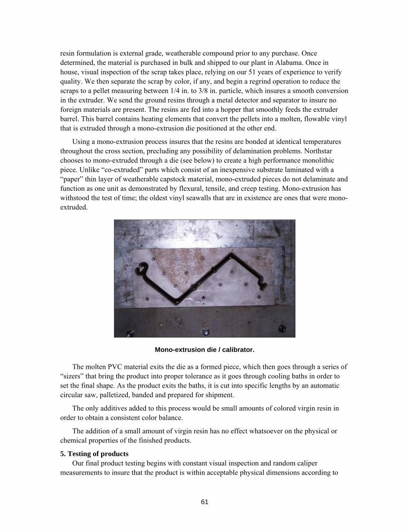
61
resin formulation is external grade, weatherable compound prior to any purchase. Once determined, the material is purchased in bulk and shipped to our plant in Alabama. Once in house, visual inspection of the scrap takes place, relying on our 51 years of experience to verify quality. We then separate the scrap by color, if any, and begin a regrind operation to reduce the scraps to a pellet measuring between 1/4 in. to 3/8 in. particle, which insures a smooth conversion in the extruder. We send the ground resins through a metal detector and separator to insure no foreign materials are present. The resins are fed into a hopper that smoothly feeds the extruder barrel. This barrel contains heating elements that convert the pellets into a molten, flowable vinyl that is extruded through a mono-extrusion die positioned at the other end.
Using a mono-extrusion process insures that the resins are bonded at identical temperatures throughout the cross section, precluding any possibility of delamination problems. Northstar chooses to mono-extruded through a die (see below) to create a high performance monolithic piece. Unlike “co-extruded” parts which consist of an inexpensive substrate laminated with a “paper” thin layer of weatherable capstock material, mono-extruded pieces do not delaminate and function as one unit as demonstrated by flexural, tensile, and creep testing. Mono-extrusion has withstood the test of time; the oldest vinyl seawalls that are in existence are ones that were mono-extruded.
Mono-extrusion die / calibrator.
The molten PVC material exits the die as a formed piece, which then goes through a series of “sizers” that bring the product into proper tolerance as it goes through cooling baths in order to set the final shape. As the product exits the baths, it is cut into specific lengths by an automatic circular saw, palletized, banded and prepared for shipment.
The only additives added to this process would be small amounts of colored virgin resin in order to obtain a consistent color balance.
The addition of a small amount of virgin resin has no effect whatsoever on the physical or chemical properties of the finished products.
5. Testing of products Our final product testing begins with constant visual inspection and random caliper
measurements to insure that the product is within acceptable physical dimensions according to
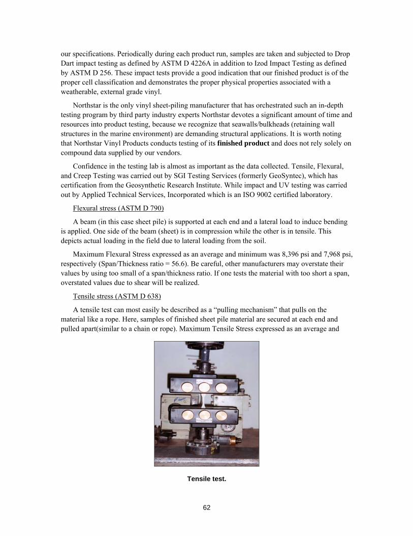
62
our specifications. Periodically during each product run, samples are taken and subjected to Drop Dart impact testing as defined by ASTM D 4226A in addition to Izod Impact Testing as defined by ASTM D 256. These impact tests provide a good indication that our finished product is of the proper cell classification and demonstrates the proper physical properties associated with a weatherable, external grade vinyl.
Northstar is the only vinyl sheet-piling manufacturer that has orchestrated such an in-depth testing program by third party industry experts Northstar devotes a significant amount of time and resources into product testing, because we recognize that seawalls/bulkheads (retaining wall structures in the marine environment) are demanding structural applications. It is worth noting that Northstar Vinyl Products conducts testing of its finished product and does not rely solely on compound data supplied by our vendors.
Confidence in the testing lab is almost as important as the data collected. Tensile, Flexural, and Creep Testing was carried out by SGI Testing Services (formerly GeoSyntec), which has certification from the Geosynthetic Research Institute. While impact and UV testing was carried out by Applied Technical Services, Incorporated which is an ISO 9002 certified laboratory.
Flexural stress (ASTM D 790)
A beam (in this case sheet pile) is supported at each end and a lateral load to induce bending is applied. One side of the beam (sheet) is in compression while the other is in tensile. This depicts actual loading in the field due to lateral loading from the soil.
Maximum Flexural Stress expressed as an average and minimum was 8,396 psi and 7,968 psi, respectively (Span/Thickness ratio = 56.6). Be careful, other manufacturers may overstate their values by using too small of a span/thickness ratio. If one tests the material with too short a span, overstated values due to shear will be realized.
Tensile stress (ASTM D 638)
A tensile test can most easily be described as a “pulling mechanism” that pulls on the material like a rope. Here, samples of finished sheet pile material are secured at each end and pulled apart(similar to a chain or rope). Maximum Tensile Stress expressed as an average and
Tensile test.
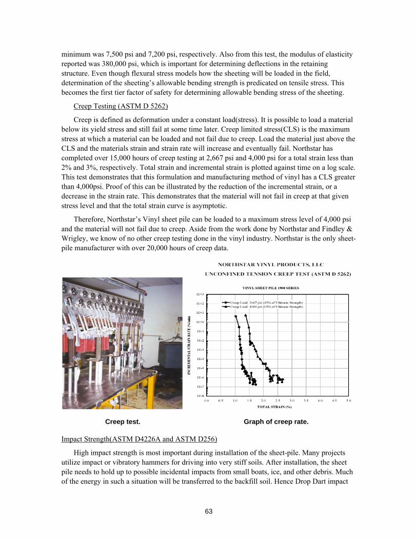
63
minimum was 7,500 psi and 7,200 psi, respectively. Also from this test, the modulus of elasticity reported was 380,000 psi, which is important for determining deflections in the retaining structure. Even though flexural stress models how the sheeting will be loaded in the field, determination of the sheeting’s allowable bending strength is predicated on tensile stress. This becomes the first tier factor of safety for determining allowable bending stress of the sheeting.
Creep Testing (ASTM D 5262)
Creep is defined as deformation under a constant load(stress). It is possible to load a material below its yield stress and still fail at some time later. Creep limited stress(CLS) is the maximum stress at which a material can be loaded and not fail due to creep. Load the material just above the CLS and the materials strain and strain rate will increase and eventually fail. Northstar has completed over 15,000 hours of creep testing at 2,667 psi and 4,000 psi for a total strain less than 2% and 3%, respectively. Total strain and incremental strain is plotted against time on a log scale. This test demonstrates that this formulation and manufacturing method of vinyl has a CLS greater than 4,000psi. Proof of this can be illustrated by the reduction of the incremental strain, or a decrease in the strain rate. This demonstrates that the material will not fail in creep at that given stress level and that the total strain curve is asymptotic.
Therefore, Northstar’s Vinyl sheet pile can be loaded to a maximum stress level of 4,000 psi and the material will not fail due to creep. Aside from the work done by Northstar and Findley & Wrigley, we know of no other creep testing done in the vinyl industry. Northstar is the only sheet-pile manufacturer with over 20,000 hours of creep data.
Creep test. Graph of creep rate.
Impact Strength(ASTM D4226A and ASTM D256)
High impact strength is most important during installation of the sheet-pile. Many projects utilize impact or vibratory hammers for driving into very stiff soils. After installation, the sheet pile needs to hold up to possible incidental impacts from small boats, ice, and other debris. Much of the energy in such a situation will be transferred to the backfill soil. Hence Drop Dart impact
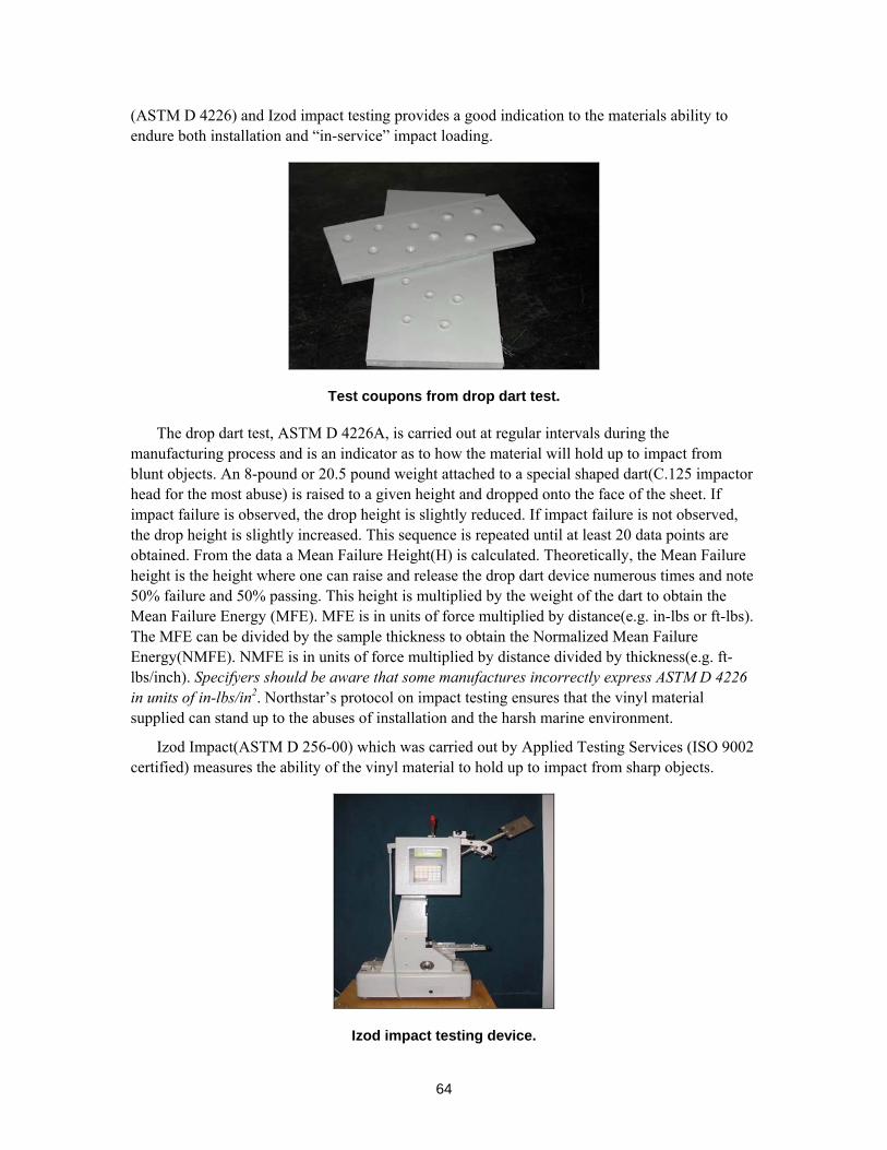
64
(ASTM D 4226) and Izod impact testing provides a good indication to the materials ability to endure both installation and “in-service” impact loading.
Test coupons from drop dart test.
The drop dart test, ASTM D 4226A, is carried out at regular intervals during the manufacturing process and is an indicator as to how the material will hold up to impact from blunt objects. An 8-pound or 20.5 pound weight attached to a special shaped dart(C.125 impactor head for the most abuse) is raised to a given height and dropped onto the face of the sheet. If impact failure is observed, the drop height is slightly reduced. If impact failure is not observed, the drop height is slightly increased. This sequence is repeated until at least 20 data points are obtained. From the data a Mean Failure Height(H) is calculated. Theoretically, the Mean Failure height is the height where one can raise and release the drop dart device numerous times and note 50% failure and 50% passing. This height is multiplied by the weight of the dart to obtain the Mean Failure Energy (MFE). MFE is in units of force multiplied by distance(e.g. in-lbs or ft-lbs). The MFE can be divided by the sample thickness to obtain the Normalized Mean Failure Energy(NMFE). NMFE is in units of force multiplied by distance divided by thickness(e.g. ft-lbs/inch). Specifyers should be aware that some manufactures incorrectly express ASTM D 4226 in units of in-lbs/in2. Northstar’s protocol on impact testing ensures that the vinyl material supplied can stand up to the abuses of installation and the harsh marine environment.
Izod Impact(ASTM D 256-00) which was carried out by Applied Testing Services (ISO 9002 certified) measures the ability of the vinyl material to hold up to impact from sharp objects.
Izod impact testing device.
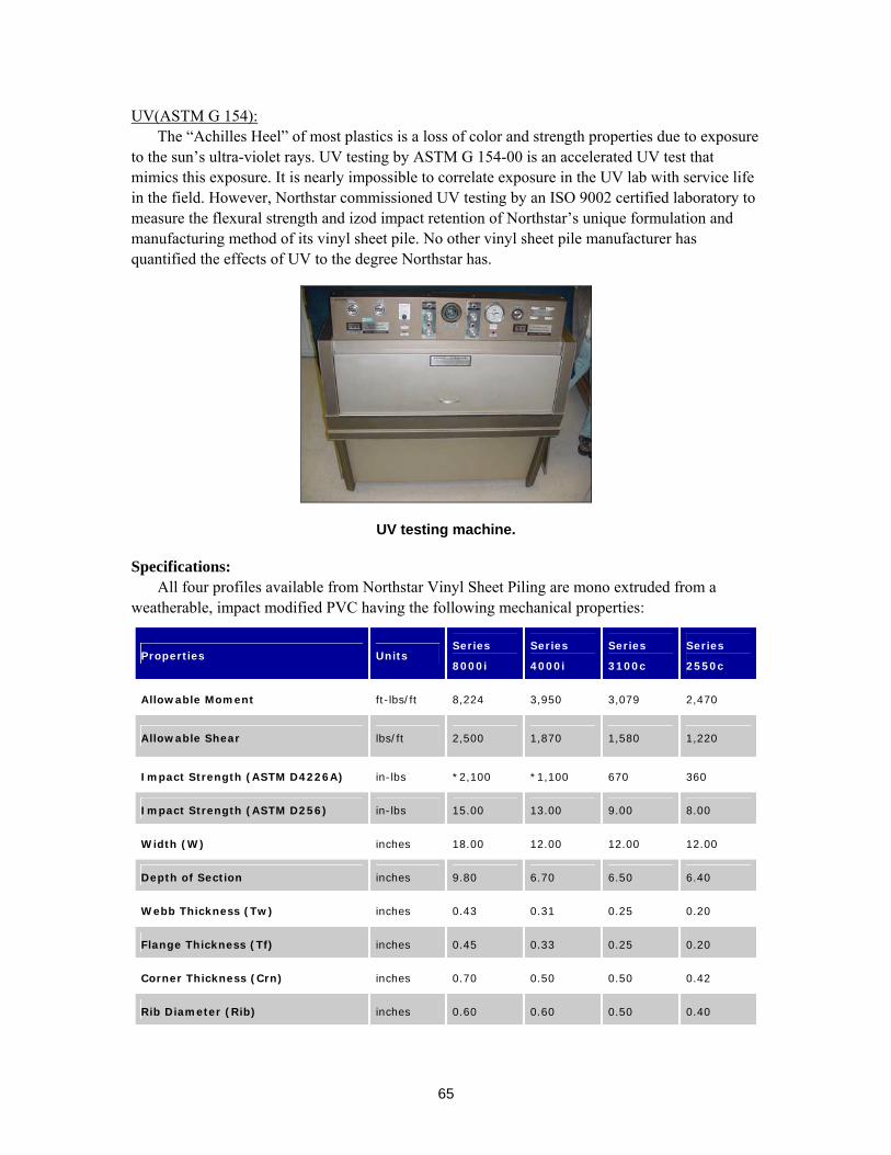
65
UV(ASTM G 154): The “Achilles Heel” of most plastics is a loss of color and strength properties due to exposure
to the sun’s ultra-violet rays. UV testing by ASTM G 154-00 is an accelerated UV test that mimics this exposure. It is nearly impossible to correlate exposure in the UV lab with service life in the field. However, Northstar commissioned UV testing by an ISO 9002 certified laboratory to measure the flexural strength and izod impact retention of Northstar’s unique formulation and manufacturing method of its vinyl sheet pile. No other vinyl sheet pile manufacturer has quantified the effects of UV to the degree Northstar has.
UV testing machine.
Specifications: All four profiles available from Northstar Vinyl Sheet Piling are mono extruded from a
weatherable, impact modified PVC having the following mechanical properties:
Properties Units Series
8000i Series
4000i Series
3100c Series
2550c
Allowable Moment ft-lbs/ft 8,224 3,950 3,079 2,470
Allowable Shear lbs/ft 2,500 1,870 1,580 1,220
Impact Strength (ASTM D4226A) in-lbs *2,100 *1,100 670 360
Impact Strength (ASTM D256) in-lbs 15.00 13.00 9.00 8.00
Width (W) inches 18.00 12.00 12.00 12.00
Depth of Section inches 9.80 6.70 6.50 6.40
Webb Thickness (Tw) inches 0.43 0.31 0.25 0.20
Flange Thickness (Tf) inches 0.45 0.33 0.25 0.20
Corner Thickness (Crn) inches 0.70 0.50 0.50 0.42
Rib Diameter (Rib) inches 0.60 0.60 0.50 0.40
66
Neutral Axis (n.a.) inches 4.90 3.35 3.25 3.20
Moment of Inertia in^4/ft 146.30 48.00 36.30 28.80
Weight lbs/ft 8.20 4.30 3.50 2.90
Modulus of Elasticity (E)
(ASTM D-790) PSI 380,000
Creep Limited Tensile Stress
(20,000 Hours per ASTM D-638) PSI 4,000 (<3% Total Strain)
Factor of Safety for Durability PSI 1.21
Peak Tensile (ASTM D-638) PSI 6,300 (<5% Total Strain)
Standard Color Grey
Mono Extrusion Yes
UV Protection (ASTM G-154) Yes
Lifetime Material Warranty Yes
Northstar not only recommends that maximum applied stresses (moments, shear, and impact) are below the
above stated allowable values, also maximum deflection should be evaluated to ensure they are acceptable for
your specific application.
The information provided above is believed to be accurate. No warranty of any kind is made as to the suitability
of Northstar Vinyl Sheet Piling for a particular application or the results obtained therefrom. Northstar
recommends that you consult with local professional (qualified engineer and/or contractor) as to the suitability
for your particular application.
*NS 8000i and NS 4000i material is too thick to execute testing procedure with standard 8 pound weight.
Therefore, the procedure was carried out with a 20.5 pound weight impacted on a sample collected from the
flange.
67
7. Historic data 7.1 The first Northstar sheet pile was introduced and installed in 1996.
7.2 No changes in raw material compounds nor manufacturing processes since 1996.
7.3 Three of the oldest installations of Northstar vinyl sheet piling.
I. Caye Chapel Island 7.3.1 Date of Mfg. 2000 7.3.2 Date of install 2000 7.3.3 Address Island off coast of Belize, Central America 7.3.4 Products Series 3700 7.3.5 Functional Requirements Hurricane Keith destroyed 2 miles of wooden bulkhead by
washing out the tieback system. Northstar Series 3700 was used to replace the original structure, complete with concrete cap and deadmen, connected with 1 in. tierods. This location subjects the vinyl to the most aggressive, year round UV conditions possible.
7.3.6 Driving Methods Water jet 7.3.7 Length 18 ft. sheets( 3 linear kilometers. ) 7.3.8 Embedment Between 8 ft and 9 ft. 7.3.9 Water depth 0 to 3 ft. 7.3.10 Above water Between 6 and 9 ft. 7.3.11 Any problems to date? None whatsoever. Since installation, this structure has
weathered 3 hurricanes, one a category 4 storm. This storm washed out the backfill, however the Northstar vinyl wall held up to the storm in thesame mode of failure as the original. There is noindication of any negative effects from UV rays.
II. Dauphin Island Causeway Project, USACE- Mobile District 7.3.1 Date of Mfg. 1998 7.3.2 Date of install 1999 7.3.3 Address Dauphin Island, AL 7.3.4 Products Series 3100 7.3.5 Functional Requirements This was a seawall, designed to protect the narrow
causeway, leading to the island and exposed to Mobile Bay wave action.
7.3.6 Driving Methods Water jet and backhoe push. 7.3.7 Length 10 to 12 ft. sheets, over 7,000 linear ft. in length 7.3.8 Embedment Only 4 ft.embedment, however rip rap was placed at the
foot and on both sides of the structure. 7.3.9 Water depth 1 ft. to 3 ft. and 100% submerged during hurricanes. 7.3.10 Above water 4 ft +/- 7.3.11 Any problems with wall? The contractor (Walter Earnest Construction @ 51-476-
68
4470) reports that this Northstar vinyl wall has since withstood 2 hurricane events since installation. He also notes that over the 2,000 ft. length, only one sheet sustained any damage during the placement of heavy rip rap against the toe of the sheets during installation.
III. Baldwin Rails to Trails Project, Florida D.O.T., Dept. Environmental Protection 7.3.1 Date of Mfg. 1999 7.3.2 Date of install 1999 7.3.3 Address City of Baldwin / Duval County, FL 7.3.4 Products Series 3100 (This was a VE change over steel sheets
costing over $200,000. Our vinyl cost was $80,000, saving the D.O.T. $120,000.
7.3.5 Functional Requirements This structure is designed as a cantilevered retaining wall for slope stabilization, run-off diversion and roadside barrier. It retains a 4 ft. column of soil in a cantilevered design, with another 3 ft. of vertical free-board acting as a pedestrian barrier.
7.3.6 Driving Methods Backhoe push plus trench and fill 7.3.7 Length 14 ft. sheets, and approximately 575 linear ft. long 7.3.8 Embedment 7 ft. embedment with a 4ft column of soil on 1 side. 7.3.9 Water depth Not a marine structure 7.3.10 Above water N/A 7.3.11 Any problems with wall? None whatsoever.
8. Life Cycle
8.1 Over 50 years of expected life cycle, however there is no real base line for determining “normal use” in a retaining structure due to the many changes in the loading factors. Our products, when incorporated into a properly engineered and installed wall, using the correct strength profile predicated on the expected loads, designed with a reasonable factor of safety, should be a serviceable wall place well beyond the 50 year mark. Our transferable warranty is a testament to our confidence in the expectation of a 50 year life cycle. Our sheet pile will outlast most of the usual components being used in most installations. The vinyl sheet pile now becomes the strongest link in the chain.
8.2 The tests that we have and are conducting can be reviewed under the earlier Section 5 of this paper. We have used 3rd party testing labs to confirm that our expectations regarding long term design strength and longevity are correct.
8.3 We can see the growing popularity of vinyl sheet pile demonstrated quite clearly in New Jersey, where vinyl has all but replaced wood sheet pile in the last 11 years. The earliest walls are in place with no change in the material since installation. This same growth can be witnessed in Florida, Louisiana, New York, Maryland, Michigan, Nebraska, the Carolina’s, Caribbean Islands, Central and South America, and nearly any where on earth where property needs protection from erosion. We can also point to the extensive use of vinyl siding and its continued market growth, which started in the late 60’s, became popular in the 70’s and is still serviceable today; 35 to 40 years later.
69
PVC was first used commercially in Germany as far back as 1935 in pipe applications. With the improvements in the compounds, UV inhibitors and impact modifiers, the PVC pipe industry still thrives. Further evidence to its weatherability is the explosive growth seen in other building products such as vinyl decking, vinyl fencing, window and door frames with new products being introduced at every building show. There is obviously a growing confidence in the uses for weatherable PVC. 9. Degradation over time
9.1 Please reference our UV testing as indicated in Section 5 of this paper. also reference additional studies as listed in Section 10.
9.2 We have not observed any measurable change in Modulus of Elasticity in any project to date. Nearly all changes observed in a retaining wall structure can be quickly associated with changes in loading, under design of the structure and/or construction failures.
9.3 Regarding long term creep, we have found that if designs are based on Creep Limited Stress below 4,000 psi, the material creep actually decreases over time. With over 20,000 hours of creep data to date, we show that incremental deflection is almost not measurable. We are seeing (2.7 x 10 −7) % based on ongoing testing.
9.4 We have not experienced any long term changes in impact resistance. The hundreds of miles of vinyl sheetpile installed in every possible climate has not experienced any measurable change in impact strength; even in the colder regions. Contractors still install vinyl in frozen conditions (usually above 20 degrees) with every possible tool, including drop hammers.
Other pertinent information. Noteable Projects
Project Name / Agency
Date
Installed Location Product Project Description
Shelter Island Causeway
USACE / NY District
Ctc. D Rackmales
212-264-9111
Approx.
1997
Shelter Island,
NY
10-12 ft
sheets
Cantelevered seawall with Rip Rap to
protect roadway from storm erosion,
over 1,000 lin ft.
US Navy / San Diego Pierwall
Blaylock Engineering
USN
1999 San Diego, CA 26-38 ft
sheets
Sheets driven as facia, then grout
pumped behind in order to create a new
wall with old wall in place.
Wallisville Reservoir Cut-off
USACE / Galveston District
1995 Trinity River,
LA
22 ft.
sheets
Sheets driven in dense clays with steel
mandrel, creating a cut-off wall, 350 ft
long, protecting bearing piles
Wood River Channel Restoration
US Fish & Wildlife, US Forest
Service, DEQ, Bureau of Land
Management, Bureau of
Reclamation
1999 Wood River,
OR
15-20 ft.
sheets
Sheets driven in channel to allow natural
plantings to take hold, establish root
system, with sheets removed in 3 -4
years.
70
Massachusetts Military Reservation
US Air Force
1999 Cape Cod, MA 14 ft.
sheets
1,105 lin. ft. of 14 ft sheets, cantilevered
4 ft and installed as a cut-off wall
designed to contain a plum of ethylene
dibromide.
Williamsburg Pump Station
USCOE / Kentucky District
Ctc. Francis “Hammer” Haynes
606-549-2710
1998 Williamsburg,
KY
22 ft.
sheets
240 lin ft. seepage barrier installed in
dense clay using steel mandrel to protect
pump station from river flooding.
City of Benicia Floodwall
City Engineering
1999 Benicia, CA 14 ft.
sheets
1,200 lin ft. of 14 ft sheets, cantilevered
to a 7 ft. height, capped with concrete to
act as a floodwall on the Sacramento
River.
Medley Landfill Containment Wall
Law Engineering
1998 Miami, FL 12 ft.
sheets
over 4,000 lin ft. cut-off wall,
cantilevered approximately 5 ft. in order
to capture water run-off, with up to 100
year service life.
National Park Svc./ Dept. of Interior
Gulf Islands National Seashore
2002 Ocean Springs,
MS
8 ft to 12
ft sheets
400 lin. Ft. of bulkhead using Series
3700, designed and spec’d by govt.
engineers.
Pymatuning State Park
Pennsylvania State Engineering
Contractor: Ashtabula Construction
Jefferson, OH
216-576-7181
1993 Linesville, PA 10 ft.
sheets
One of the earliest government
installations of vinyl sheet pile, mono-
extruded, light- weight profile designed
in the weakest shape and subjected to
annual ice push for 10 years
Maximization of section strength through design Finite Element Modeling used in Northstar design (FEM) (ANSYS Version 5.7):
Prior to construction, FEM has been used in the design of aircraft, spacecraft, automobiles, bridge beams, and skyscrapers to name a few. FEM provides a rigorous way of modeling the load and analyzing the stresses and deflections of a given part. The dozens of FEM runs carried out by Georgia Institute of Technology on Northstar’s behalf, utilizes millions of tiny 3-D bricks as “building blocks” of the vinyl sheet pile. Here, one can see how a Z-shaped profile behaves under loading. Northstar’s intent for running the dozens of FEM runs is two fold: 1) determine the optimum geometry of the Z-shaped profile, and 2) confirm/validate the practical use of the linear beam model for (σ = M/S) determining the maximum applied stresses in the sheeting. In the FEM, sheets were loaded to their maximum allowable rated moment based on their section modulus and the linear beam equation. Next, stresses (major and minor) as well as deflections were calculated utilizing FEM. Maximum stresses calculated from FEM were compared with maximum allowable stresses for the applicable vinyl compound. Also, stresses and deflections were compared to the linear beam equation. It is interesting to note that a Z-shaped sheet of uniform thickness develops higher stresses in the corners (web/flange intersection) than predicted by the linear beam equation. It is Northstar’s opinion that only by substantially thickening the
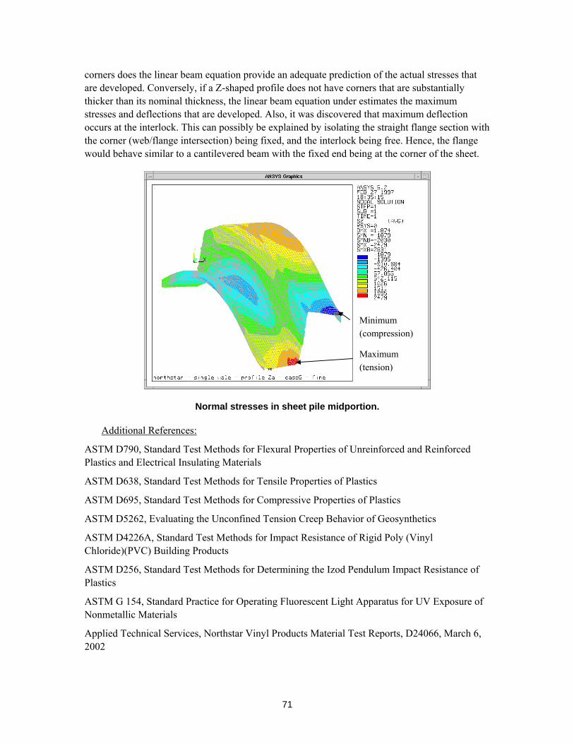
71
corners does the linear beam equation provide an adequate prediction of the actual stresses that are developed. Conversely, if a Z-shaped profile does not have corners that are substantially thicker than its nominal thickness, the linear beam equation under estimates the maximum stresses and deflections that are developed. Also, it was discovered that maximum deflection occurs at the interlock. This can possibly be explained by isolating the straight flange section with the corner (web/flange intersection) being fixed, and the interlock being free. Hence, the flange would behave similar to a cantilevered beam with the fixed end being at the corner of the sheet.
Normal stresses in sheet pile midportion.
Additional References:
ASTM D790, Standard Test Methods for Flexural Properties of Unreinforced and Reinforced Plastics and Electrical Insulating Materials
ASTM D638, Standard Test Methods for Tensile Properties of Plastics
ASTM D695, Standard Test Methods for Compressive Properties of Plastics
ASTM D5262, Evaluating the Unconfined Tension Creep Behavior of Geosynthetics
ASTM D4226A, Standard Test Methods for Impact Resistance of Rigid Poly (Vinyl Chloride)(PVC) Building Products
ASTM D256, Standard Test Methods for Determining the Izod Pendulum Impact Resistance of Plastics
ASTM G 154, Standard Practice for Operating Fluorescent Light Apparatus for UV Exposure of Nonmetallic Materials
Applied Technical Services, Northstar Vinyl Products Material Test Reports, D24066, March 6, 2002
Minimum (compression)
Maximum (tension)
72
SGI Testing Services (formerly GeoSyntec Consultants), Final Report 10000 Hour Unconfined Tension Creep Testing, Northstar Vinyl Sheet Piles 1900 and 9400 Series, Project Number SGI 1035, July 26, 2001
SGI Testing Services (formerly GeoSyntec Consultants), Report Update 15,000 Hour Unconfined Tension Creep Testing, Northstar Vinyl Sheet Piles 1900 and 9400 Series, Project Number SGI 1035, November 15, 2001
SGI Testing Services (formerly GeoSyntec Consultants), Northstar Vinyl Products, LLC., Flexural Strength Testing(ASTM D 790), SGI#1035, August 27, 2001
GeoSyntec Consultants, Vinyl Sheet Pile Tensile Testing(ASTM D 638), GeoSyntect Project No. GLI 1147, February 25, 2000
Georgia Institute of Technology, College of Engineering, CALS Technology Center, 3D Finite Element Modeling of Northstar 1900 and 3700 profile, Peak, Russell S., PhD., June 17, 1997
Georgia Institute of Technology, Engineering Information Systems Laboratory, 3D Finite Element Modeling of Northstar 2500 profile, Birkes, Angela Y., PhD., October 30, 2001
Hartman Engineering, Summary Excerpted From Report of Investigation and Test Program Related to Behavior of Steel Sheet Piling Subjected to Hydrostatic Test Loading, Prepared for Bethlehem Steel Corportation and L.B. Foster Company, Hartman, Richard J., P.E., PhD, Neal, John A., PhD, June 29, 1992
Brown University, Division of Engineering, Polymer Engineering and Science, 16-Year Creep of Polyethylene and PVC, W.N. Findley, J.F. Tracy, 8/74, Volume 14, No. 8
73
APPENDIX C. SEAWALL STRUCTURE SIMULATION RESULTS
By Uday Vaidya, University of Alabama at Birmingham
Figure C1 shows a brief demonstration of the installation procedure for a Northstar Vinyl
Seawall. The complete structure is erected using individual units of the modular structure as shown in the Figure C2. The individual units are 12” wide. The dimensions mentioned are those for the product series 3100c. These structures are made from the high impact and UV stabilized Vinyl Compound, mono-extruded from pellets or regrind PVC.
Figure C1. Typical installation of the seawall structures.
According to the specification by the Northstar to provide adequate shear strength, resistance to web crippling, and drivability during installation, the profile shall have the following geometric properties:
• Ribs- two within the web of the profile having the mentioned diameter. • Rib spacing shall be approximately one-third increments along the length of the web. • Corners (intersection between web and flange) – alternate interior angles of the profile
shall be 95°-110°. Also, corner thickness shall be at least 50% greater than the nominal wall thickness.
• If profile does not have ribs or thickened corners, profiles average minimum thickness shall be at least the wall thickness noted above multiplied by 1.5.
Profiles with ribs/knobs protruding from the flanges will not be allowed.
Feature Dimension (in.)
Width (W) 12 Depth (H) 6.5 Webb Thickness (Tw) 0.25 Flange Thickness (Tf) 0.25 Corner Thickness (Crn) 0.5 Rib Diameter (Rib) 0.5 Neutral Axis (n.a.) 3.25 Flange Length 5
Figure C2. Cross section of the seawall structure.
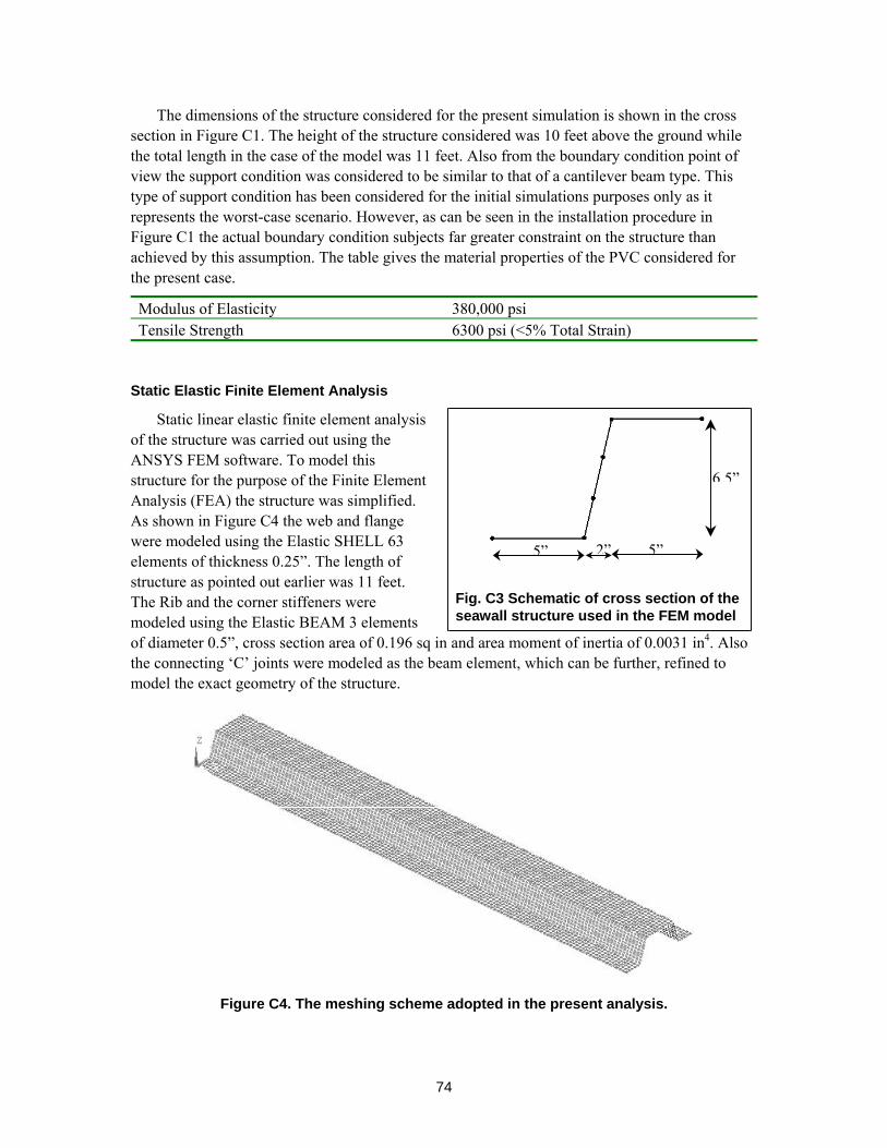
74
5” 5”2”
6.5”
Fig. C3 Schematic of cross section of the seawall structure used in the FEM model
The dimensions of the structure considered for the present simulation is shown in the cross section in Figure C1. The height of the structure considered was 10 feet above the ground while the total length in the case of the model was 11 feet. Also from the boundary condition point of view the support condition was considered to be similar to that of a cantilever beam type. This type of support condition has been considered for the initial simulations purposes only as it represents the worst-case scenario. However, as can be seen in the installation procedure in Figure C1 the actual boundary condition subjects far greater constraint on the structure than achieved by this assumption. The table gives the material properties of the PVC considered for the present case.
Modulus of Elasticity 380,000 psi Tensile Strength 6300 psi (<5% Total Strain)
Static Elastic Finite Element Analysis
Static linear elastic finite element analysis of the structure was carried out using the ANSYS FEM software. To model this structure for the purpose of the Finite Element Analysis (FEA) the structure was simplified. As shown in Figure C4 the web and flange were modeled using the Elastic SHELL 63 elements of thickness 0.25”. The length of structure as pointed out earlier was 11 feet. The Rib and the corner stiffeners were modeled using the Elastic BEAM 3 elements of diameter 0.5”, cross section area of 0.196 sq in and area moment of inertia of 0.0031 in4. Also the connecting ‘C’ joints were modeled as the beam element, which can be further, refined to model the exact geometry of the structure.
Figure C4. The meshing scheme adopted in the present analysis.
75
The material type used was linear elastic with material property as given as in above Table. The structure was made 132” long however the analysis was carried out considering that the height of the wall above the ground was 120”. To model this condition the constraint was applied to the bottom 12” section by constraining all degrees of freedom for this section. Also the node at the interfaces between the bottom 12” and structure above the ground was only constraint for UX, UY, and UZ while the all the rotational freedoms were allowed.
The load applied to the structure was uniform pressure of 0.5 psi. In actual condition the pressure from the water level will have a gradient increasing from top to bottom. However in this case the pressure was determined by considering that the maximum pressure applied by the water level of height ‘h’ can be given by
P = ρgh
where P = pressure ρ = density of water g = acceleration due to gravity h = height of the water level (120”).
Substituting the standard values in the above equation the maximum static pressure applied by the water level is 0.433 psi. Hence the constant pressure more than the actual maximum pressure tends to overload the structure and hence can be considered as a attempt to take into account the dynamic loading of the structure due to the waves in the water body. It should be noted that the conditions considered for the model would give the worst-case scenario results. Any attempt to model the actual structure under the more appropriate boundary condition will result in the performance prediction of the structure better than the one obtained from the present model.
The results from the present FEA were analyzed with respect to maximum stress and maximum strain developed in the structure. Figure C5 shows the displacement of the structure. The maximum displacement as can be expected is observed at the tip of the seawall and is 32”. This value however will be much lower in presence of the wooden frame to which these seawall structures are attached.
Figure C6 shows first principal stress distribution in the structure. As can be seen from the figure that the maximum stress is developed at the edge where the structure emerges from the earth surface or the support condition. The maximum stress value of 8449 psi seems to be larger than the maximum tensile strength of 6300 psi of the material. However the development of stresses in this localized area is because of the large deflection allowed by the present model. Also this analysis being linear elastic in nature doesn’t allows for any plastic deformation effects which can reduce the stress concentration much before such a large stress concentration is realized.
Figure C7 shows the maximum first principal strain in the structure. As the case should be the maximum stress and maximum strain region does coincide. However the maximum principle strain can be observed to be approximately 2.1%, which is far less than the maximum strain to failure of 5% for the material under consideration. This phenomenon again can be attributed to the linear elastic nature of the simulation.
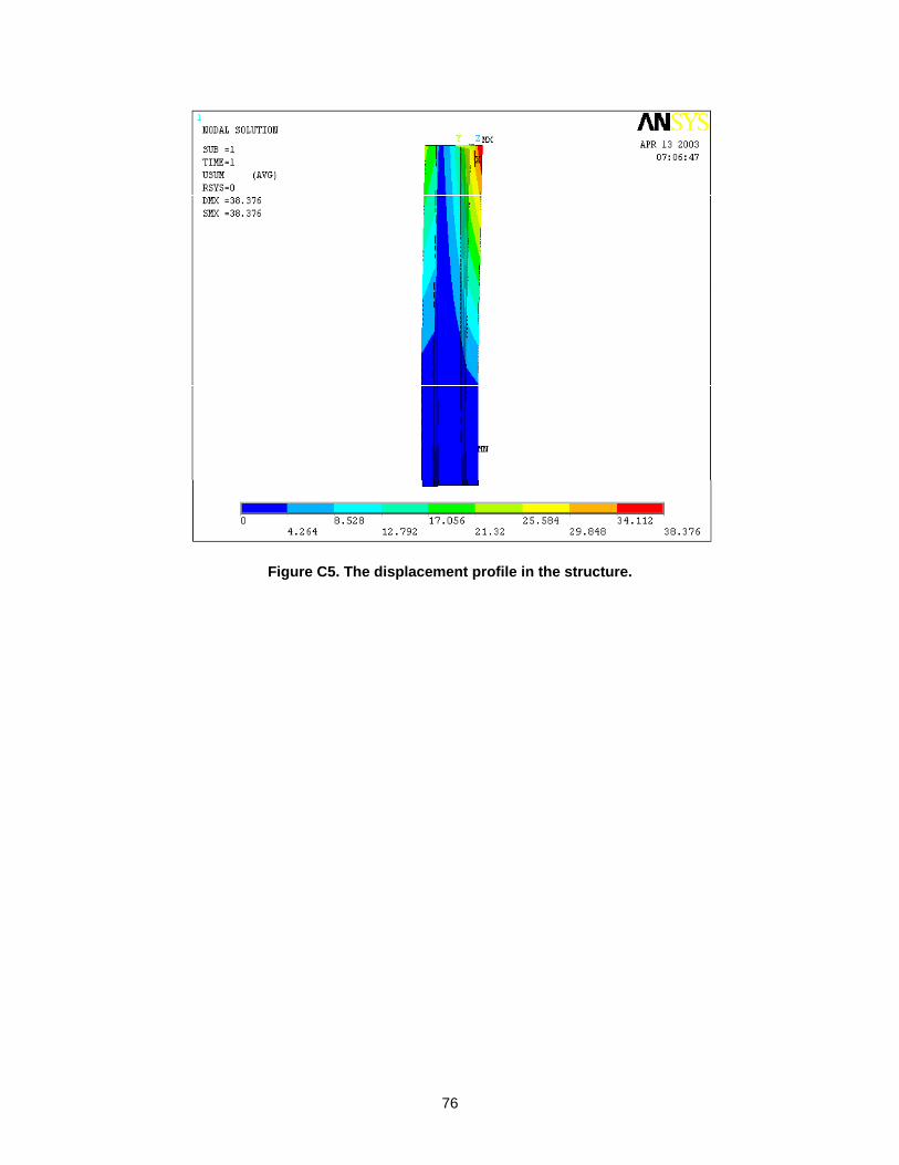
76
Figure C5. The displacement profile in the structure.
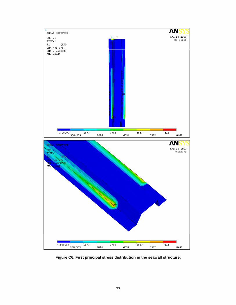
77
Figure C6. First principal stress distribution in the seawall structure.
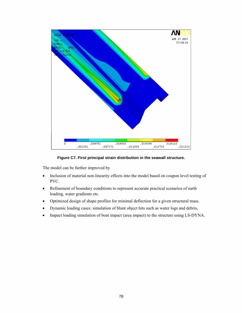
78
Figure C7. First principal strain distribution in the seawall structure.
The model can be further improved by
• Inclusion of material non-linearity effects into the model based on coupon level testing of PVC.
• Refinement of boundary conditions to represent accurate practical scenarios of earth loading, water gradients etc.
• Optimized design of shape profiles for minimal deflection for a given structural mass. • Dynamic loading cases: simulation of blunt object hits such as water logs and debris. • Impact loading simulation of boat impact (area impact) to the structure using LS-DYNA.
79
APPENDIX D: TRIP REPORT BY VIC AGOSTINELLI – MEETING ON VINYL SHEET PILING IN THE NEW ORLEANS DISTRICT ON 27 MARCH 2003
MEMORANDUM (TRIP REPORT) FOR MIKE MELLON FROM VICTOR M. AGOSTINELLI
CEMVD-TD-TS 2 April 2003 MEMORANDUM FOR: Mr. Mike Fallon, CEMVD-TD-T SUBJECT: Trip Report by Vic Agostinelli – Meeting on Vinyl Sheet Piling in the New Orleans District on 27 March 2003 1. Purpose and Background The undersigned attended a meeting in New Orleans District on 27 March 2003 on the MVN funding of research by Dr. Piyush Dutta, USACE Cold Region Research and Engineering Laboratory, to determine the suitability of using vinyl sheet piling as hurricane and flood protection I-Walls on projects in the MVN. Currently there is a HQUSACE Engineering Construction Bulletin (ECB) No. 2002-31, 28 October 2002, subject: Vinyl Sheet Piling that establishes USACE policy prohibiting use of this product in above the ground applications where there is risk of life safety and widespread property damage in event of failure, particularly flood and/or hurricane protection projects. The ECB identifies areas of concern that have to be addressed before using this product in these type of applications and would require a waiver from HQUSACE if the product is recommended for use in these applications. Because of the economy the vinyl piles are claimed to have over conventional steel or concrete I-Walls the MVN is interested in addressing these concerns by funding research to investigate if these products can be safely used for the life of the project. This trip report serves as the undersigned’s accounting of the subject meeting. 2. Meeting Attendees Dr. Piyush K. Dutta (Presentor) ERDC-CRREL-NH Professor Uday Vaidya University of Alabama Professor David Hui University of New Orleans Mr. Vic Agostinelli MVD Mr. Walter Baumy MVN Mr. Carl Guggenheimer MVN Mr. John Bivona MVN Mr. Thomas Wright MVN Mr. Allen Coates MVN Ms. Julie Oliphant MVN Mr. Michael Brennan MVM Mr. Brett Herr MVN Mrs. Carolyn Earl MVN Mr. Frank Vicodamia MVN
80
3. Presentation by Dr. Dutta and Notes on the Presentation Dr. Dutta explained the scope of his work was limited to literature search, inquiries to the manufacturers concerning their product, some limited testing on the materials to verify manufacturers claims on vinyl and to address some of the concerns expressed in the ECB on vinyl. Dr. Dutta indicated that the scope of his work did not include coming up with a design procedure for designing safely vinyl sheet piling for flood or hurricane protection applications nor to answer the functional concerns with respect to excessive deflection, vandalism, resistance to damage from fire that were also expressed in the ECB. The following were some of the highlights of Dr. Dutta’s presentation and ensuing discussions: a. Creep is an issue that must be considered when using vinyl. Creep is movement that is time dependent. Where there will be sustained loading over time this must be considered in designs when vinyl is used. b. Vinyl sheet piling is a weak material when compared with steel sheet piling. It has a modulus of elasticity of roughly one percent of steel and a tensile strength of roughly 10 percent of steel. There is approximately four times the elongation of vinyl to the elongation of steel to reach each material’s breaking strength respectively. c. Vinyl sheet piling is subject to degradation (brittleness) with respect to resistance impact loading over time. One manufacturer indicated a 40 per cent reduction in resistance to impact loading with time (50 year life). This issue would need to be addressed along with a load case criteria established for impact when considering vinyl because of this degradation and the weakness of the material. Normally impact loads are not design considerations for steel or concrete I-Walls. d. Because of the low material strength of vinyl, low resistance to creep, and the fact that the material behaves non-linearly, deflection is an even greater concern when using this product. Therefore any design must assure that deflection is not to the magnitude that would impair the function of the vinyl floodwall and the design procedure must be sophisticated enough to model accurately the deformations causing the deflections. It was noted that USACE policy criteria requires a flood or hurricane protection wall to be capable of performing successfully with water to the top of the wall on the unprotected side of the wall. However it was discussed that deflection due to creep may not be a big problem for floodwall or hurricane applications since these loads are normally short term duration over the life of the project. e. Testing conducted by Dr. Dutta and his associates as well as research of existing vinyl applications did not show significant degradation of tensile and flexural strengths of vinyl with time. UV radiation and boiling tests were both conducted in conjunction with this determination. f. Literature search showed that different manufactures have different safety factors they use in giving the safe loading capacity of their product. There are no industry standards on how to qualify the capacities of the vinyl sheet piling sections nor how it is manufactured. Some of the manufacturers responses to Dr. Dutta’s questions point to faults in their competitor’s processes as weaknesses of their competitor’s product. Specifications would have to address these issues as to
81
what constitutes adequacy for the intended purpose so that competitive bidding can be achieved on USACE projects. g. As mentioned above the vinyl is subject to non-linear behavior. Conventional beam analyses may not be applicable. Design guidance will need to be established to assure successful behavior of the vinyl structure based on an accurate model to be determined and designed to resist the anticipated loading over the life of the project. This will entail an agreement on what constitutes acceptable performance behaviors for this product by the USACE. h. The vulnerability of vinyl wall to damage from vandalism or fire was discussed. These are issues that would have to be considered in the decision process to use vinyl. Vinyl walls because of their soft material and relatively low melting point would be much more likely to be damaged from vandalism and fire than steel or concrete walls. A simple grass or brush fire could severely damage a vinyl wall and its ability to function as designed. These would have to be considerations that would have to be addressed on projects that have life safety implications where vinyl sheet piling is used. i. The undersigned requested a copy of the information presented by Dr. Dutta at the meeting in his power point presentation. Dr. Dutta indicated that he would either send this information out on a CD to those who requested the info or make the information available on a ftp site for access. Dr. Dutta also indicated he planned to finalize his report covering the work he agreed to perform for MVN on vinyl under the original scope agreement within 30 days. Additional funding would be needed to cover other issues in the ECB not covered by the original scope of Dr. Dutta’s work. 4. Other Discussions a. There was discussion by MVN representatives that the District is currently considering using vinyl sheet piling for an I-Wall section for local protection for the Pailet Basin, Section 205 Study CAP project. The undersigned suggested that if the District is definitely going to propose use of vinyl sheet piling it should a request for a waiver to ECB 2002-31 with backup information addressing all the issues raised in the ECB and get approval of this waiver before the report is submitted, since the ECB is regarded as HQUSACE policy and HQUSACE would need to approve any exception to the policy. b. It was mentioned in Dr. Dutta’s presentation that he had visited a constructed reach of a vinyl sheet piling I-Wall used for hurricane protection (above ground protection) that was understood to be constructed in the 1990’s on Westwego Canal site by MVN. The undersigned was unfamiliar with this reach of wall and how it was designed. It would appear to the undersigned that this section of vinyl sheet piling as well as any other similar applications that have been constructed by MVN should be checked based on the ongoing research to assure that these sections are adequate for the intended purpose, especially if there are life safety implications in event of failure, where these applications currently exist. c. There was some discussion on the reason MVN was considering using vinyl sheet piling I-walls over steel or concrete I-Walls for flood or hurricane protection. The reason MVN cited was for cost savings. The undersigned pointed out that any accurate cost savings claimed of vinyl over
82
steel or concrete would in his opinion need to be based on knowing answers to the issues raised in the ECB including the issue pertaining to the design model that would need to be followed and minimum USACE design criteria standards to be met when using vinyl – all issues yet to be determined. /s/ Victor M. Agosatinelli CF: Mr. Walter Baumy, CEMVN-ED Mr. Carl Guggenheimer, CEMVN-ED-TF Dr. Piyush Dutta, ERDC-CRREL-NH Mr. Brett Herr, CEMVN-PM-W Mrs. Carolyn Earl, CEMVN-PM-W Mrs. Anjana Chudgar, CECW-EWS Mr. Stacey Anastos, CENAD-MT-EC-T Dr. Reed Mosher, ERDC-SL-MS Mr. Frank Johnson, CEMVD-TD-TS Mr. Steve Cobb, CEMVD-MD-P Mrs. Lexine Cool, CEMVD-DD-PP Mr. Ken Klaus, CEMVD-TD-TG