a study on dewatering effect as a liquefaction ... papers/nakai...tohoku earthquake. examination of...
TRANSCRIPT
6th International Conference on Earthquake Geotechnical Engineering 1-4 November 2015 Christchurch, New Zealand
A Study on Dewatering Effect as a Liquefaction Countermeasure for
Existing Residential Areas by Centrifuge Shaking Table Tests
S. Nakai1, T. Sekiguchi2 and H. Mano3
ABSTRACT Mihama-ku of Chiba City which consists entirely of reclaimed ground has suffered extensive
liquefaction damage during the 2011 Tohoku Earthquake. This paper first describes the outline of its damage followed by a detailed examination of the applicability of dewatering as a counter-measure against liquefaction for future earthquakes. The examination includes construction of a subsurface soil model of the affected area, centrifuge shaking table tests of structure-soil models, numerical simulation of test results, numerical evaluation of the target site for which dewatering is planned. From this study, it was found that dewatering is effective in that it can increase the thickness of non-liquefied soil layer more than a dewatered depth and decrease the ground settlement due to liquefaction.
Introduction
The 2011 Tohoku Earthquake with the magnitude of 9.0 that struck eastern Japan on March 11 caused extensive liquefaction-induced damage over a wide area especially along the coast of Tokyo Bay. Mihama-ku (Mihama Ward) of Chiba City, located east of Tokyo, is one of the heavily affected areas. This ward consists entirely of reclaimed ground and reclamation was done by hydraulic filling of dredged soils taken from the sea bed. A large number of residential houses suffered from significant subsidence and tilting because of liquefaction to the extent that it caused severe health disturbances. In reaction to extensive liquefaction damage, the government of Japan enacted a new law which help local governments to implement liquefaction countermeasures for existing residential areas and the Ministry of Land, Infrastructure, Transport and Tourism proposed two alternatives as countermeasures: dewatering and grid-form ground improvement. Chiba City decided to apply dewatering to one of the heavily affected areas in Mihama-ku and conducted a demonstration experiment. Ishihara (1985) pointed out that almost no liquefaction induced damage to a house is found when there exists a non-liquefied soil with an enough thickness. According to this fact, dewatering can be considered here as a means to mitigate the damage to a house by creating such a layer rather than expecting an increase of liquefaction resistance due to partial saturation of soils (Yegian et al. (2007), for example). In order to examine the effectiveness of dewatering in the target area, a series of centrifuge shaking table tests as well as numerical simulation analyses have been conducted, followed by an evaluation of its effectiveness when applied to the target area. This paper first describes the outline of liquefaction-induced damage in Mihama-ku during the 2011 1Professor, Graduate School of Engineering, Chiba University, Chiba, Japan, [email protected] 2Associate Professor, Graduate School of Engineering, Chiba University, Chiba, Japan, [email protected] 3Chief Research Engineer, Research Institute, Shimizu Corporation, Tokyo, Japan, [email protected]
Tohoku Earthquake. Examination of the effectiveness of dewatering is then made by conducting centrifuge shaking table tests, followed by their numerical simulation analyses. Finally, the applicability of dewatering to the target area is discussed by conducting a similar analysis.
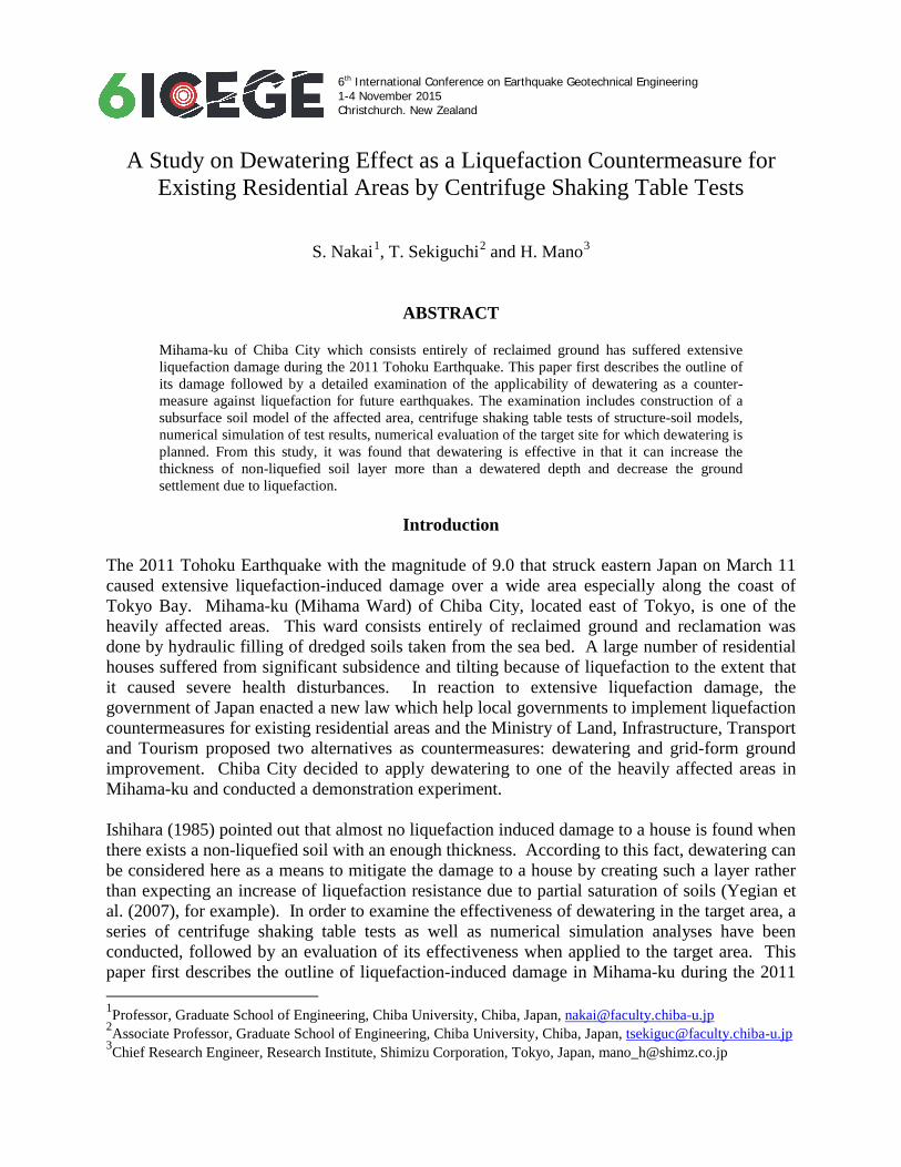
Outline of Liquefaction Damage in Mihama-ku The authors have conducted an intensive survey of liquefaction damage (sand boiling) right after the quake. The target of survey includes all the public roads and parks where it was able to enter at that time. The severity of sand boiling due to liquefaction was classified into three levels: heavy, minor and none. Sand boiling with the overflow size diameter of 1 m or larger is classified as heavy, while that of smaller than 1 m is classified as minor. The area where no sand boiling was found is categorized as none. Figure 1 shows the distribution of sand boiling in the form of 50 m square grid. Grids with no colors represent the areas that could not be entered at the time of survey. As can be seen in the figure, heavy sand boiling was observed throughout entire Mihama-ku. Its distribution, however, is not uniform. It is understood that this non-uniform distribution of liquefaction damage can be explained by the complexity of the subsurface soil structure in this region (Sekiguchi et al. (2012a, 2012b)), which resulted from the land reclamation process (Nakai et al. (2013)).
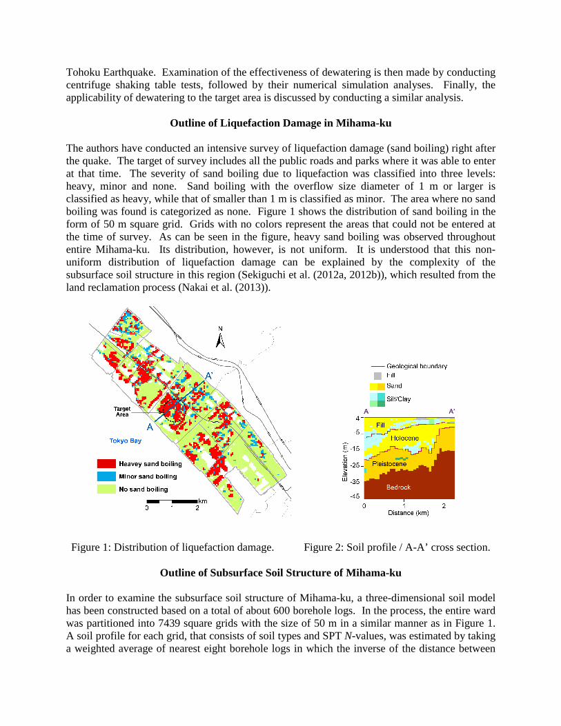
Figure 1: Distribution of liquefaction damage. Figure 2: Soil profile / A-A’ cross section.
Outline of Subsurface Soil Structure of Mihama-ku In order to examine the subsurface soil structure of Mihama-ku, a three-dimensional soil model has been constructed based on a total of about 600 borehole logs. In the process, the entire ward was partitioned into 7439 square grids with the size of 50 m in a similar manner as in Figure 1. A soil profile for each grid, that consists of soil types and SPT N-values, was estimated by taking a weighted average of nearest eight borehole logs in which the inverse of the distance between
the center of a grid and the borehole location is used as a weighting function. The shear wave velocities were then evaluated from the soil types and SPT N-values by using empirical equations in this area (Nagata et al. (2008)). The estimated shear wave velocity profiles were validated by comparing the amplification characteristics of the soil model with the microtremor (ambient vibration) measurement results conducted at about 200 locations throughout the ward. Figure 2 shows a cross sectional view of soil profile along the line A-A' in Figure 1 which passes through the target area. From this figure, it can be seen that the soil profile is fairly complex and that, in the target area, there exists a thin layer of clayey soils and sandy soils above and beneath it. It is believed that the superficial sandy soils have liquefied during the 2011 event. A proposed dewatering method is that the existing residential area is enclosed by a steel sheet pile wall that is installed to a clayey layer located under a liquefiable sandy layer. Thus, a combination of a sheet pipe wall and a clayey layer at an appropriate depth is necessary for this method. It is confirmed from Figure 2 that this condition can be met in the target area.
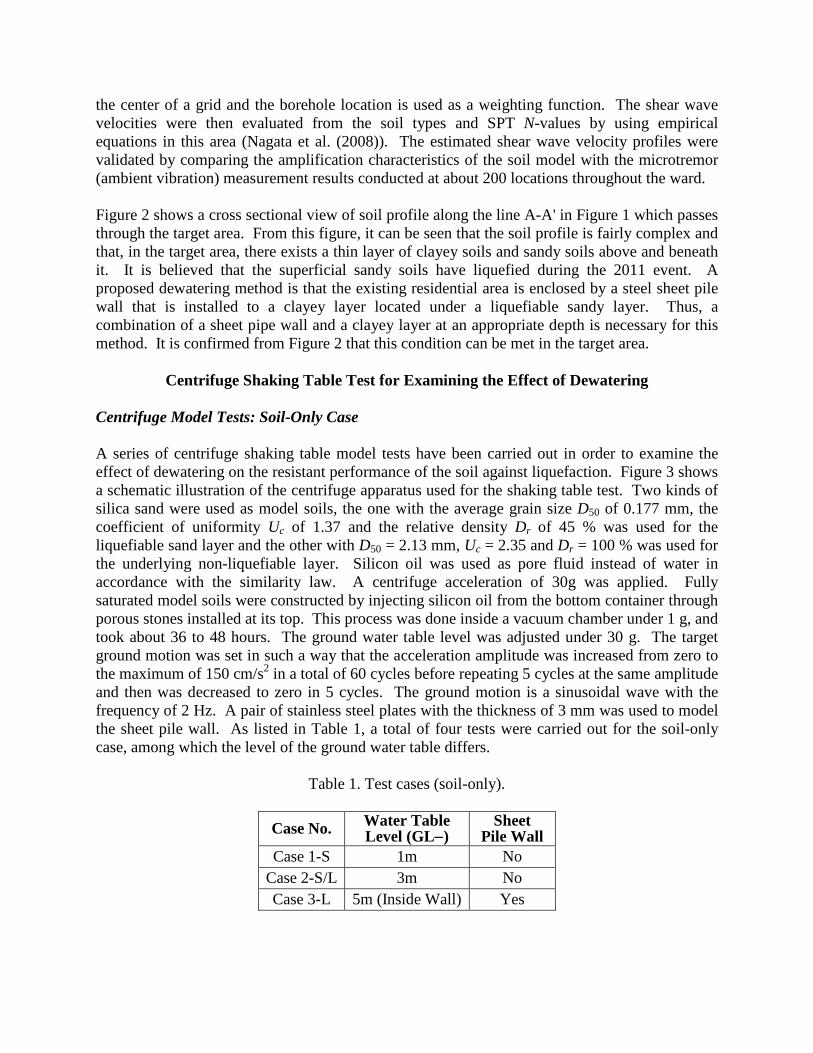
Centrifuge Shaking Table Test for Examining the Effect of Dewatering Centrifuge Model Tests: Soil-Only Case A series of centrifuge shaking table model tests have been carried out in order to examine the effect of dewatering on the resistant performance of the soil against liquefaction. Figure 3 shows a schematic illustration of the centrifuge apparatus used for the shaking table test. Two kinds of silica sand were used as model soils, the one with the average grain size D50 of 0.177 mm, the coefficient of uniformity Uc of 1.37 and the relative density Dr of 45 % was used for the liquefiable sand layer and the other with D50 = 2.13 mm, Uc = 2.35 and Dr = 100 % was used for the underlying non-liquefiable layer. Silicon oil was used as pore fluid instead of water in accordance with the similarity law. A centrifuge acceleration of 30g was applied. Fully saturated model soils were constructed by injecting silicon oil from the bottom container through porous stones installed at its top. This process was done inside a vacuum chamber under 1 g, and took about 36 to 48 hours. The ground water table level was adjusted under 30 g. The target ground motion was set in such a way that the acceleration amplitude was increased from zero to the maximum of 150 cm/s2 in a total of 60 cycles before repeating 5 cycles at the same amplitude and then was decreased to zero in 5 cycles. The ground motion is a sinusoidal wave with the frequency of 2 Hz. A pair of stainless steel plates with the thickness of 3 mm was used to model the sheet pile wall. As listed in Table 1, a total of four tests were carried out for the soil-only case, among which the level of the ground water table differs.
Table 1. Test cases (soil-only).
Case No. Water Table Level (GL−)
Sheet Pile Wall
Case 1-S 1m No Case 2-S/L 3m No Case 3-L 5m (Inside Wall) Yes
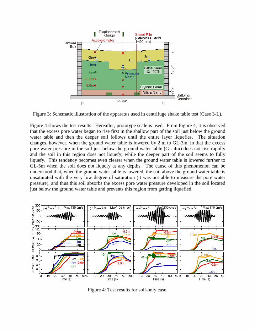
Figure 3: Schematic illustration of the apparatus used in centrifuge shake table test (Case 3-L). Figure 4 shows the test results. Hereafter, prototype scale is used. From Figure 4, it is observed that the excess pore water began to rise first in the shallow part of the soil just below the ground water table and then the deeper soil follows until the entire layer liquefies. The situation changes, however, when the ground water table is lowered by 2 m to GL-3m, in that the excess pore water pressure in the soil just below the ground water table (GL-4m) does not rise rapidly and the soil in this region does not liquefy, while the deeper part of the soil seems to fully liquefy. This tendency becomes even clearer when the ground water table is lowered further to GL-5m when the soil does not liquefy at any depths. The cause of this phenomenon can be understood that, when the ground water table is lowered, the soil above the ground water table is unsaturated with the very low degree of saturation (it was not able to measure the pore water pressure), and thus this soil absorbs the excess pore water pressure developed in the soil located just below the ground water table and prevents this region from getting liquefied.
Figure 4: Test results for soil-only case.

Table 2: Test cases (building-soil).
Case No. Water Table Level (GL−)
Sheet Pile Wall
Case 1 1m No Case 2 3m No Case 3 5m (Inside Wall) Yes
Centrifuge Model Tests: Building-Soil Interaction Case In order to examine the effect of dewatering on the behavior of residential small houses during shaking, a series of additional tests were conducted by placing a structure model on the ground surface. The model is made of stainless steel with the prototype size of 4.5 m width and depth, and the average contact pressure due to its weight is 14.5 kPa. In order to consider the weight eccentricity, the structure is partially two-storied, as shown in Photo 1. The soil properties and excitation method is approximately the same as the previous cases without the structure. Table 2 summarizes the test cases.
Photo 1: Building (residential house) model. Figure 5 shows the time history of input ground motions applied to the bottom of the shear box together with excess pore water pressures and estimated excess pore water pressure ratios at the locations under the structure. From the figure it is pointed out that the soil just below the ground water level of GL-2m does not liquefy any more, which can be understood by the increase of the overburden pressure due to the structure. Other than this, the test results are similar to the previous soil-only case. Although not shown in Figure 5, it was also found from the test that the excess pore water dissipates more rapidly as the thickness of unsaturated layer becomes larger and that the settlement as well as the differential settlement of the structure becomes much smaller as the ground water table becomes lower. It is noted that the differential settlement resulted in the order 1/1000 which is so small that human can never recognize the inclination. From these results, it is confirmed that dewatering is quite effective.
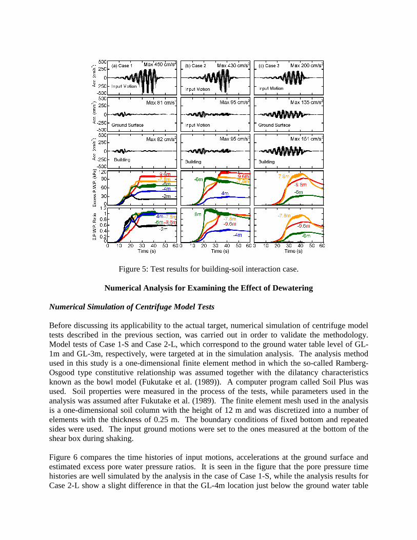
Figure 5: Test results for building-soil interaction case.
Numerical Analysis for Examining the Effect of Dewatering Numerical Simulation of Centrifuge Model Tests Before discussing its applicability to the actual target, numerical simulation of centrifuge model tests described in the previous section, was carried out in order to validate the methodology. Model tests of Case 1-S and Case 2-L, which correspond to the ground water table level of GL-1m and GL-3m, respectively, were targeted at in the simulation analysis. The analysis method used in this study is a one-dimensional finite element method in which the so-called Ramberg-Osgood type constitutive relationship was assumed together with the dilatancy characteristics known as the bowl model (Fukutake et al. (1989)). A computer program called Soil Plus was used. Soil properties were measured in the process of the tests, while parameters used in the analysis was assumed after Fukutake et al. (1989). The finite element mesh used in the analysis is a one-dimensional soil column with the height of 12 m and was discretized into a number of elements with the thickness of 0.25 m. The boundary conditions of fixed bottom and repeated sides were used. The input ground motions were set to the ones measured at the bottom of the shear box during shaking. Figure 6 compares the time histories of input motions, accelerations at the ground surface and estimated excess pore water pressure ratios. It is seen in the figure that the pore pressure time histories are well simulated by the analysis in the case of Case 1-S, while the analysis results for Case 2-L show a slight difference in that the GL-4m location just below the ground water table
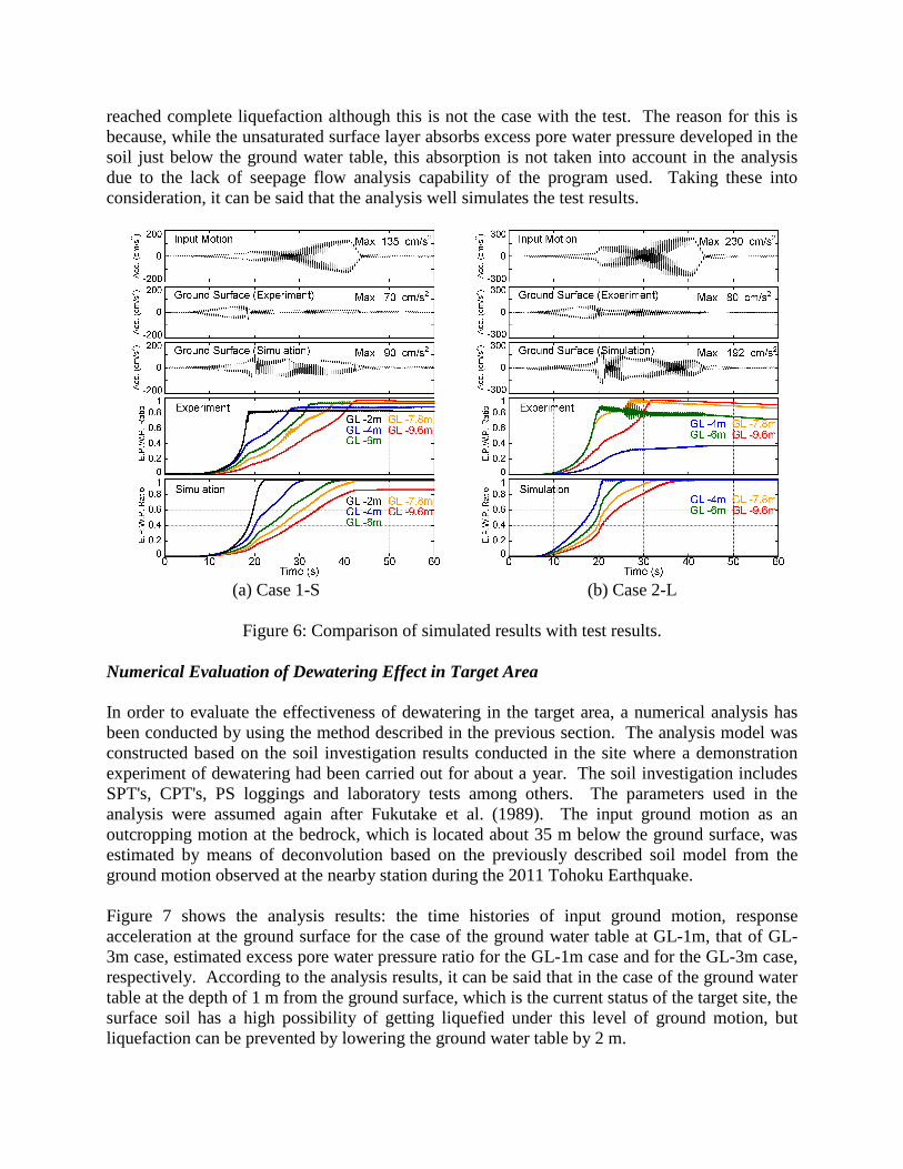
reached complete liquefaction although this is not the case with the test. The reason for this is because, while the unsaturated surface layer absorbs excess pore water pressure developed in the soil just below the ground water table, this absorption is not taken into account in the analysis due to the lack of seepage flow analysis capability of the program used. Taking these into consideration, it can be said that the analysis well simulates the test results.
(a) Case 1-S (b) Case 2-L
Figure 6: Comparison of simulated results with test results. Numerical Evaluation of Dewatering Effect in Target Area In order to evaluate the effectiveness of dewatering in the target area, a numerical analysis has been conducted by using the method described in the previous section. The analysis model was constructed based on the soil investigation results conducted in the site where a demonstration experiment of dewatering had been carried out for about a year. The soil investigation includes SPT's, CPT's, PS loggings and laboratory tests among others. The parameters used in the analysis were assumed again after Fukutake et al. (1989). The input ground motion as an outcropping motion at the bedrock, which is located about 35 m below the ground surface, was estimated by means of deconvolution based on the previously described soil model from the ground motion observed at the nearby station during the 2011 Tohoku Earthquake. Figure 7 shows the analysis results: the time histories of input ground motion, response acceleration at the ground surface for the case of the ground water table at GL-1m, that of GL-3m case, estimated excess pore water pressure ratio for the GL-1m case and for the GL-3m case, respectively. According to the analysis results, it can be said that in the case of the ground water table at the depth of 1 m from the ground surface, which is the current status of the target site, the surface soil has a high possibility of getting liquefied under this level of ground motion, but liquefaction can be prevented by lowering the ground water table by 2 m.
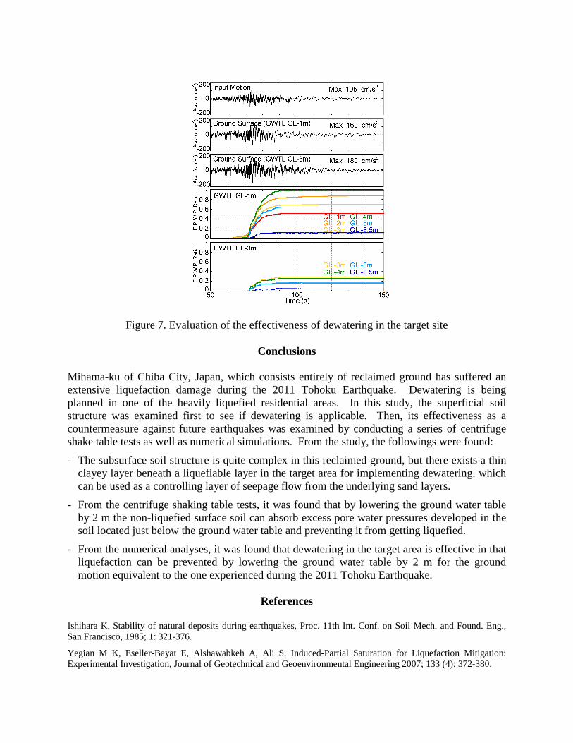
Figure 7. Evaluation of the effectiveness of dewatering in the target site
Conclusions Mihama-ku of Chiba City, Japan, which consists entirely of reclaimed ground has suffered an extensive liquefaction damage during the 2011 Tohoku Earthquake. Dewatering is being planned in one of the heavily liquefied residential areas. In this study, the superficial soil structure was examined first to see if dewatering is applicable. Then, its effectiveness as a countermeasure against future earthquakes was examined by conducting a series of centrifuge shake table tests as well as numerical simulations. From the study, the followings were found:
- The subsurface soil structure is quite complex in this reclaimed ground, but there exists a thin clayey layer beneath a liquefiable layer in the target area for implementing dewatering, which can be used as a controlling layer of seepage flow from the underlying sand layers.
- From the centrifuge shaking table tests, it was found that by lowering the ground water table by 2 m the non-liquefied surface soil can absorb excess pore water pressures developed in the soil located just below the ground water table and preventing it from getting liquefied.
- From the numerical analyses, it was found that dewatering in the target area is effective in that liquefaction can be prevented by lowering the ground water table by 2 m for the ground motion equivalent to the one experienced during the 2011 Tohoku Earthquake.
References
Ishihara K. Stability of natural deposits during earthquakes, Proc. 11th Int. Conf. on Soil Mech. and Found. Eng., San Francisco, 1985; 1: 321-376.
Yegian M K, Eseller-Bayat E, Alshawabkeh A, Ali S. Induced-Partial Saturation for Liquefaction Mitigation: Experimental Investigation, Journal of Geotechnical and Geoenvironmental Engineering 2007; 133 (4): 372-380.
Sekiguchi T, Nakai S. Liquefaction Damage Distribution in Mihama Ward of Chiba City during 2011 Tohoku Earthquake, Proc. 15th World Conference on Earthquake Engineering, Portugal, 2012, 10pp.
Sekiguchi T, Nakai S. Effects of Surface Soil Structure on Liquefaction Damage in Mihama Ward of Chiba City, Journal of Japan Association for Earthquake Engineering 2012; 12 (5): 21-35. (in Japanese)
Nakai S, Sekiguchi T. Analysis of liquefaction damage in Mihama-ku of Chiba city due to 2011 Tohoku earthquake, BUTSURI-TANSA 2013; 66 (1): 37-43. (in Japanese)
Nagata Y, Nakai S, Sekiguchi T. S-wave velocity of surface soils in northwest region of Chiba prefecture, AIJ Journal of Technology and Design 2008; 14 (28): 429-432. (in Japanese)
Fukutake K, Matsuoka H. A unified law for dilatancy under multi-directional simple shearing, Proc. Japan Society of Civil Engineers 1989; 412/III-12: 143-151. (in Japanese)