a sulfur cathode with pomegranate‐like cluster...
TRANSCRIPT
CO
MM
UN
ICATIO
N
© 2015 WILEY-VCH Verlag GmbH & Co. KGaA, Weinheim (1 of 6) 1500211wileyonlinelibrary.com
A Sulfur Cathode with Pomegranate-Like Cluster Structure
Weiyang Li , Zheng Liang , Zhenda Lu , Hongbin Yao , Zhi Wei Seh , Kai Yan , Guangyuan Zheng , and Yi Cui *
Dr. W. Li, Z. Liang, Dr. Z. Lu, Dr. H. Yao, Z. W. Seh, Dr. K. Yan Department of Materials Science and Engineering Stanford University Stanford , CA 94305 , USA E-mail: [email protected] Dr. G. Zheng Department of Chemical Engineering Stanford University Stanford , CA 94305 , USA Dr. Y. Cui Stanford Institute for Materials and Energy Sciences SLAC National Accelerator Laboratory 2575 Sand Hill Road Menlo Park , CA 94025 , USA
DOI: 10.1002/aenm.201500211
sulfur cathode design should have the following attributes: (1) an immobilizer with nanoscale internal void spaces for sulfur infusion to ensure high utilization of the active material; (2) good electrical property; (3) a short conductive pathway to facilitate facile ion/electron transport; (4) suffi cient empty space to accommodate sulfur volume expansion and discharge prod-ucts deposition; (5) an interconnected and closed architecture to trap polysulfi des; (6) limited contact between sulfur and elec-trolyte to minimize polysulfi des dissolution and side reactions; and (7) a high tapped density for achieving a high volumetric energy density. Carbon-based nanostructures, such as gra-phene/graphene oxide, [ 38–40 ] hollow/porous carbon fi ber, [ 37,41–44 ] mesoporous carbon, [ 45–47 ] and microporous carbon paper, [ 48 ] have played critical roles as framework for sulfur cathodes. These designs have successfully fulfi lled some of the above requirements. Nevertheless, it was very diffi cult for the above-mentioned nanoscale carbon-based host materials to maintain a stable contact between each particle during galvanostatic cycling. The bad contact tends to introduce a high interparticle resistance and thus a general poor electrical property and poor rate capability. Moreover, the normal carbon-based matrix is not able to accommodate a high mass loading of sulfur per unit volume, which lowers the entire cell volumetric energy density.
Along this line, inspired by the internal structure of the pomegranate, our group developed a bottom-up approach for the fabrication of a novel silicon–carbon pomegranate-like cluster structure, [ 11 ] which greatly increased the tapped den-sity of silicon anode and showed excellent electrochemical per-formance as anode material for LIB. Herein, we integrate all the design criteria for an ideal sulfur cathode as mentioned into this unique structure. We report the development of the pomegranate-like carbon cluster–encapsulated sulfur cathode with the following characteristics: (1) the nanosized primary particles enable high active material utilization; (2) the densely packed primary hollow carbon particles contribute to stable interparticle contact during cycling; (3) the conductive carbon cluster backbone functions as an effi cient pathway for fast elec-tron transport; (4) controlled empty spaces within the cluster structure to accommodate sulfur volume change and facilitate uniform Li 2 S deposition; (5) interconnected channels inside the secondary particle allow physical confi nement of the poly-sulfi des; (6) carbon coating covers the entire secondary particle so that the electrolyte accessibility is limited on the surface of the microsized secondary particles, which prevents electrolyte further fl ooding into the primary particles; and (7) space-effi -cient packing of nanosized primary particles inside the micro-sized secondary particle promotes a high tapped density and therefore a high volumetric energy density.
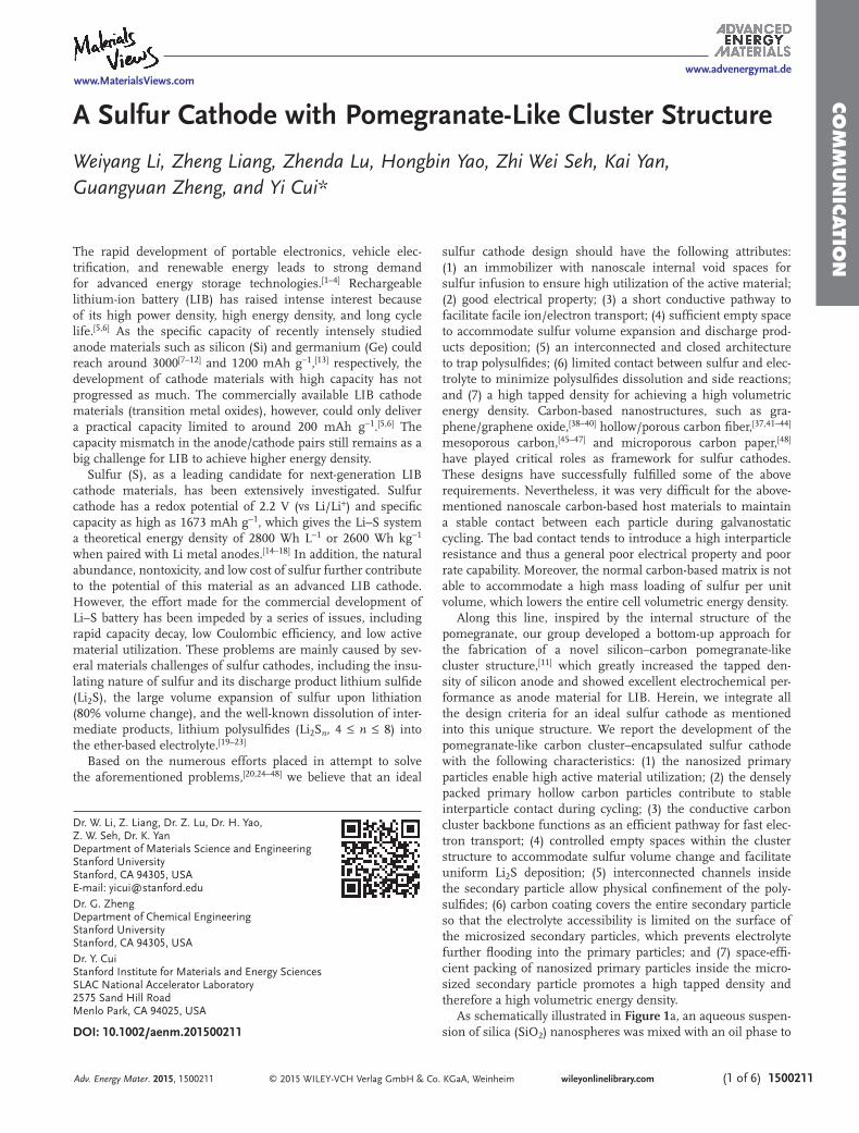
As schematically illustrated in Figure 1 a, an aqueous suspen-sion of silica (SiO 2 ) nanospheres was mixed with an oil phase to
The rapid development of portable electronics, vehicle elec-trifi cation, and renewable energy leads to strong demand for advanced energy storage technologies. [ 1–4 ] Rechargeable lithium-ion battery (LIB) has raised intense interest because of its high power density, high energy density, and long cycle life. [ 5,6 ] As the specifi c capacity of recently intensely studied anode materials such as silicon (Si) and germanium (Ge) could reach around 3000 [ 7–12 ] and 1200 mAh g −1 , [ 13 ] respectively, the development of cathode materials with high capacity has not progressed as much. The commercially available LIB cathode materials (transition metal oxides), however, could only deliver a practical capacity limited to around 200 mAh g −1 . [ 5,6 ] The capacity mismatch in the anode/cathode pairs still remains as a big challenge for LIB to achieve higher energy density.
Sulfur (S), as a leading candidate for next-generation LIB cathode materials, has been extensively investigated. Sulfur cathode has a redox potential of 2.2 V (vs Li/Li + ) and specifi c capacity as high as 1673 mAh g −1 , which gives the Li–S system a theoretical energy density of 2800 Wh L −1 or 2600 Wh kg −1 when paired with Li metal anodes. [ 14–18 ] In addition, the natural abundance, nontoxicity, and low cost of sulfur further contribute to the potential of this material as an advanced LIB cathode. However, the effort made for the commercial development of Li–S battery has been impeded by a series of issues, including rapid capacity decay, low Coulombic effi ciency, and low active material utilization. These problems are mainly caused by sev-eral materials challenges of sulfur cathodes, including the insu-lating nature of sulfur and its discharge product lithium sulfi de (Li 2 S), the large volume expansion of sulfur upon lithiation (80% volume change), and the well-known dissolution of inter-mediate products, lithium polysulfi des (Li 2 S n , 4 ≤ n ≤ 8) into the ether-based electrolyte. [ 19–23 ]
Based on the numerous efforts placed in attempt to solve the aforementioned problems, [ 20,24–48 ] we believe that an ideal
Adv. Energy Mater. 2015, 1500211
www.MaterialsViews.comwww.advenergymat.de
CO
MM
UN
ICATI
ON
© 2015 WILEY-VCH Verlag GmbH & Co. KGaA, Weinheim1500211 (2 of 6) wileyonlinelibrary.com
form a microemulsion. After the removal of water and organics, the SiO 2 nanospheres self-assembled to form a close-packed SiO 2 cluster. The obtained cluster was then coated with a thin layer of resorcinolformaldehyde resin (RF) through solution synthesis. The RF shell was carbonized under argon atmos-phere and the resulting carbon covered SiO 2 cluster was used
as a sacrifi cial template. After all the SiO 2 was etched by hydro-fl uoric acid (HF) solution, the carbon cluster was obtained. Figure 1 b,c are the typical scanning electron microscopy (SEM) images of the as-formed carbon clusters under different mag-nifi cations. The microsized secondary particle with a diameter mainly in the range of 1–2 µm consists of uniform spherical
Adv. Energy Mater. 2015, 1500211
www.MaterialsViews.comwww.advenergymat.de
Figure 1. Schematic diagram of the fabrication process of carbon clusters and the corresponding morphology. a) The carbon clusters were prepared by a bottom-up microemulsion approach; b,c) SEM images of carbon clusters under different magnifi cations; d,e) TEM images of carbon clusters under different magnifi cations. RF: resorcinolformaldehyde resin.
CO
MM
UN
ICATIO
N
© 2015 WILEY-VCH Verlag GmbH & Co. KGaA, Weinheim (3 of 6) 1500211wileyonlinelibrary.com
hollow primary particles (see Figure S1, Supporting Informa-tion, for the particle size distribution of the carbon clusters). These primary particles form a space-effi cient packing arrange-ment, which permits stable contact during cycling and thus a lower interparticle resistance. The morphology of a single carbon cluster is studied by the transmission electron micros-copy (TEM). As illustrated in Figure 1 d, the average diam-eter of the primary hollow carbon particle is about 120 nm. The internal void space is displayed as the lower intensity area (Figure 1 d). The thickness of the primary particles is deter-mined to be 4–5 nm for the outer shell while 1–2 nm for the inner shell. As a result, the carbon clusters could be able to accommodate a high sulfur mass loading.
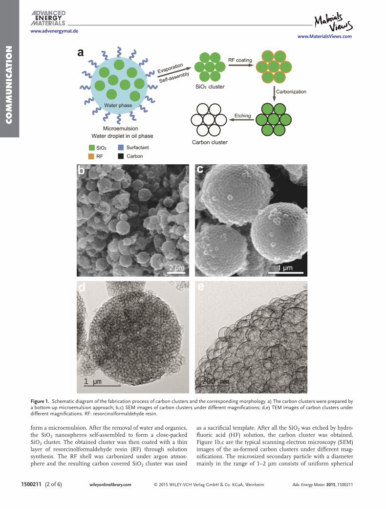
Sulfur was infi ltrated into the cluster matrix by a melt-dif-fusion process. [ 25 ] The thus formed sulfur-impregnated carbon cluster composite is denoted as C/S cluster. Figure 2 a–c depicts the SEM and TEM characterizations of a single secondary particle after sulfur infusion. No random sulfur deposition is observed at the surface of the carbon clusters. Due to the fact that sulfur is heavier than carbon, sulfur appears as the dark region with uniform intensity under TEM (Figure 2 b,c), revealing homogeneous encapsulation of sulfur within the primary carbon nanospheres. The presence of sulfur is fur-ther demonstrated by the energy-dispersive X-ray spectroscopy (EDS) analysis (Figure S2, Supporting Information) of the C/S clusters. The EDS spectrum clearly shows strong peaks from sulfur and carbon. In order to lessen the capacity decay due to the polysulfi de dissolution, the outer surface of the C/S cluster was further coated with a layer of conductive polymer, poly(3,4-ethylenedioxythiophene) (PEDOT) as a protective layer, denoted as PEDOT-C/S cluster. We then treated the PEDOT-C/S cluster with toluene to remove some sulfur in the outer shell to create empty space to accommodate the volume change of sulfur upon cycling. Figure 2 d–f shows the morphology of the toluene-treated PEDOT-C/S cluster. The partial dissolution of sulfur in the outer shells can be clearly revealed in Figure 2 f.
To study the overall electrochemical prop-erty of the novel carbon cluster–encapsulated sulfur cathodes, galvanostatic cycling test and inductively coupled plasma (ICP) analysis were performed. 2032-type coin cells were assembled with lithium foil as the counter electrode and sulfur-impregnated carbon clusters as the working electrode. Control cells were fabricated with sulfur-impregnated carbon spheres, denoted as C/S spheres, as the working electrode (the dimension of these carbon spheres is the same as that of the primary particles in the carbon clusters). In addition, another sample was prepared by uti-lizing the toluene-treated PEDOT-C/S clusters as the working electrode. No extra conductive additive, such as Super-P carbon black was used. Lithium bis(trifl uoromethanesulfonyl)imide (LiTFSI) (1 M ) dissolved in co-solvent of 1,2-dimethoxyethane (DME) and 1,3-dioxo-lane (DOL) with 1 wt% of lithium nitrate (LiNO 3 ) was employed as the electrolyte. LiNO 3 was applied to help reduce the shuttle
effect and passivate the lithium metal anode. [ 22,49 ] The specifi c capacities were all calculated based on sulfur mass only and the typical sulfur mass loading was 2 mg cm −2 .
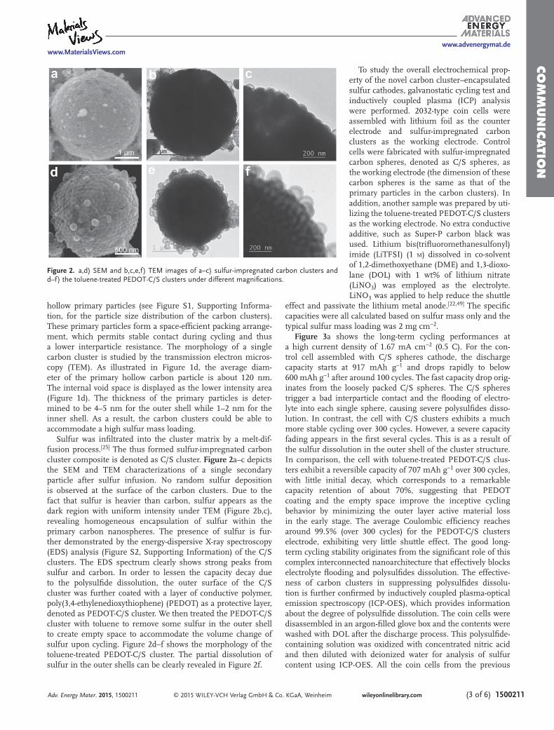
Figure 3 a shows the long-term cycling performances at a high current density of 1.67 mA cm −2 (0.5 C). For the con-trol cell assembled with C/S spheres cathode, the discharge capacity starts at 917 mAh g −1 and drops rapidly to below 600 mAh g −1 after around 100 cycles. The fast capacity drop orig-inates from the loosely packed C/S spheres. The C/S spheres trigger a bad interparticle contact and the fl ooding of electro-lyte into each single sphere, causing severe polysulfi des disso-lution. In contrast, the cell with C/S clusters exhibits a much more stable cycling over 300 cycles. However, a severe capacity fading appears in the fi rst several cycles. This is as a result of the sulfur dissolution in the outer shell of the cluster structure. In comparison, the cell with toluene-treated PEDOT-C/S clus-ters exhibit a reversible capacity of 707 mAh g −1 over 300 cycles, with little initial decay, which corresponds to a remarkable capacity retention of about 70%, suggesting that PEDOT coating and the empty space improve the inceptive cycling behavior by minimizing the outer layer active material loss in the early stage. The average Coulombic effi ciency reaches around 99.5% (over 300 cycles) for the PEDOT-C/S clusters electrode, exhibiting very little shuttle effect. The good long-term cycling stability originates from the signifi cant role of this complex interconnected nanoarchitecture that effectively blocks electrolyte fl ooding and polysulfi des dissolution. The effective-ness of carbon clusters in suppressing polysulfi des dissolu-tion is further confi rmed by inductively coupled plasma-optical emission spectroscopy (ICP-OES), which provides information about the degree of polysulfi de dissolution. The coin cells were disassembled in an argon-fi lled glove box and the contents were washed with DOL after the discharge process. This polysulfi de-containing solution was oxidized with concentrated nitric acid and then diluted with deionized water for analysis of sulfur content using ICP-OES. All the coin cells from the previous
Adv. Energy Mater. 2015, 1500211
www.MaterialsViews.comwww.advenergymat.de
Figure 2. a,d) SEM and b,c,e,f) TEM images of a–c) sulfur-impregnated carbon clusters and d–f) the toluene-treated PEDOT-C/S clusters under different magnifi cations.
CO
MM
UN
ICATI
ON
© 2015 WILEY-VCH Verlag GmbH & Co. KGaA, Weinheim1500211 (4 of 6) wileyonlinelibrary.com
electrochemical testing were subject to the same treatment. As presented in Figure 3 b, in the case of C/S spheres, the dis-solved sulfur in electrolyte keeps increasing to 36% after 100 cycles. While for the C/S clusters and PEDOT-C/S clusters, only 20% and 12% of the total sulfur mass was lost, respectively. It is noted that the sulfur content for C/S clusters quickly increases in the fi rst ten cycles, and then becomes steady from 10 to 100 cycles. The large amount of sulfur loss in the beginning for C/S clusters elucidates the outer shell active material dissolution with little protection, consistent with the cycling performance showing in Figure 3 a. In comparison, the sulfur in the inner cores of the C/S clusters are very diffi cult to diffuse out owing to the complex interconnected channels inside, which showed a relatively steady trend in the following cycles. After a layer of PEDOT coating, the sulfur loss during the inceptive cycling is mitigated and overall change in sulfur mass in the electrolyte is steady. We further carried out electrochemical impedance spectroscopy (EIS) measurements (see Figure S3, Supporting Information) of the toluene-treated PEDOT-C/S cluster cathode at different states: at open circuit voltage (OCV) before cycling, and at 2.09 V (the lower voltage plateau) during the 1st and 100th discharge cycle at 0.5 C. Previous studies showed that the semicircle in the high-frequency region could refl ect the charge transfer resistance at the conductive agent interface, while the semicircle in the middle frequency range could be attributed to the mass transport (formation of insoluble polysulfi de species at the lower voltage plateau). [ 22,50 ] As shown in Figure S3 (Sup-porting Information), we can see that the high-frequency semi-circle resistances are all very small at different states, showing the fast interfacial charge transfer. Moreover, the middle fre-quency semicircle resistance did not change much after 100 cycles, indicating the excellent structural stability of the cluster electrode.
Rate performances from 0.1 to 3 C of the cells made from PEDOT-C/S clusters are displayed in Figure 3 c
(1 C = 3.35 mA cm −2 ). The cell is able to deliver a high revers-ible capacity of over 700 mAh g −1 (about 733 mAh g −1 ) at a very high current of 3 C, or about 10 mA cm −2 equivalent. By calculating the volume of the sulfur electrode in our experi-ment, the volumetric energy density of the sulfur cathode at 3 C is 1290 Wh L −1 . The steady and negligible capacity drop over various cycling rates ranging from 0.1 to 3 C reveals stability and robustness of the carbon cluster structure. The discharge capacity returns to 99.5% of its original value (1050 mAh g −1 ) when the current rate is switched abruptly back from 3 to 0.2 C. Moreover, the excellent rate capability indicates excellent kinetics as a result of the space-effi cient packing of the primary particles. For further investigation of the electrochemical prop-erties, voltage profi les of the galvanostatic cycling are provided in Figure 3 d at different current rates. These discharge voltage curves display the typical two-plateau behavior of Li–S battery. Moreover, the fl at second discharge plateau for current rate as high as 3 C indicates a small kinetic barrier. The cell yields a reversible discharge capacity of 1200, 1100, 1020, 972, 842, and 733 mAh g −1 at 0.1, 0.2, 0.5, 1, 2, and 3 C, respectively.
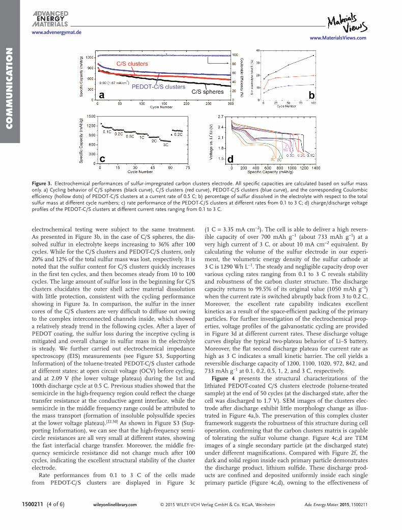
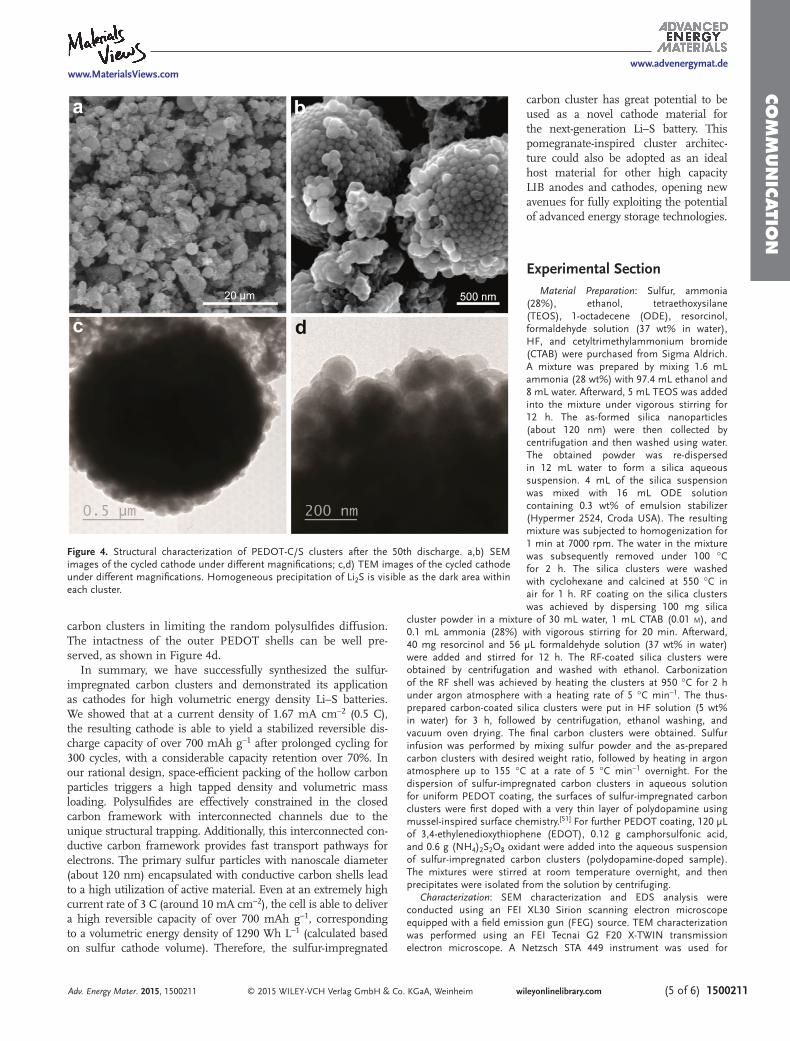
Figure 4 presents the structural characterizations of the lithiated PEDOT-coated C/S clusters electrode (toluene-treated sample) at the end of 50 cycles (at the discharged state, after the cell was discharged to 1.7 V). SEM images of the clusters elec-trode after discharge exhibit little morphology change as illus-trated in Figure 4 a,b. The preservation of this complex cluster framework suggests the robustness of this structure during cell operation, confi rming that the carbon clusters matrix is capable of tolerating the sulfur volume change. Figure 4 c,d are TEM images of a single secondary particle (at the discharged state) under different magnifi cations. Compared with Figure 2 f, the dark and solid region inside each primary particle demonstrates the discharge product, lithium sulfi de. These discharge prod-ucts are confi ned and deposited uniformly inside each single primary particle (Figure 4 c,d), owning to the effectiveness of
Adv. Energy Mater. 2015, 1500211
www.MaterialsViews.comwww.advenergymat.de
Figure 3. Electrochemical performances of sulfur-impregnated carbon clusters electrode. All specifi c capacities are calculated based on sulfur mass only. a) Cycling behavior of C/S spheres (black curve), C/S clusters (red curve), PEDOT-C/S clusters (blue curve), and the corresponding Coulombic effi ciency (hollow dots) of PEDOT-C/S clusters at a current rate of 0.5 C; b) percentage of sulfur dissolved in the electrolyte with respect to the total sulfur mass at different cycle numbers; c) rate performance of the PEDOT-C/S clusters at different rates from 0.1 to 3 C; d) charge/discharge voltage profi les of the PEDOT-C/S clusters at different current rates ranging from 0.1 to 3 C.
CO
MM
UN
ICATIO
N
© 2015 WILEY-VCH Verlag GmbH & Co. KGaA, Weinheim (5 of 6) 1500211wileyonlinelibrary.com
carbon clusters in limiting the random polysulfi des diffusion. The intactness of the outer PEDOT shells can be well pre-served, as shown in Figure 4 d.
In summary, we have successfully synthesized the sulfur-impregnated carbon clusters and demonstrated its application as cathodes for high volumetric energy density Li–S batteries. We showed that at a current density of 1.67 mA cm −2 (0.5 C), the resulting cathode is able to yield a stabilized reversible dis-charge capacity of over 700 mAh g −1 after prolonged cycling for 300 cycles, with a considerable capacity retention over 70%. In our rational design, space-effi cient packing of the hollow carbon particles triggers a high tapped density and volumetric mass loading. Polysulfi des are effectively constrained in the closed carbon framework with interconnected channels due to the unique structural trapping. Additionally, this interconnected con-ductive carbon framework provides fast transport pathways for electrons. The primary sulfur particles with nanoscale diameter (about 120 nm) encapsulated with conductive carbon shells lead to a high utilization of active material. Even at an extremely high current rate of 3 C (around 10 mA cm −2 ), the cell is able to deliver a high reversible capacity of over 700 mAh g −1 , corresponding to a volumetric energy density of 1290 Wh L −1 (calculated based on sulfur cathode volume). Therefore, the sulfur-impregnated
carbon cluster has great potential to be used as a novel cathode material for the next-generation Li–S battery. This pomegranate-inspired cluster architec-ture could also be adopted as an ideal host material for other high capacity LIB anodes and cathodes, opening new avenues for fully exploiting the potential of advanced energy storage technologies.
Experimental Section Material Preparation : Sulfur, ammonia
(28%), ethanol, tetraethoxysilane (TEOS), 1-octadecene (ODE), resorcinol, formaldehyde solution (37 wt% in water), HF, and cetyltrimethylammonium bromide (CTAB) were purchased from Sigma Aldrich. A mixture was prepared by mixing 1.6 mL ammonia (28 wt%) with 97.4 mL ethanol and 8 mL water. Afterward, 5 mL TEOS was added into the mixture under vigorous stirring for 12 h. The as-formed silica nanoparticles (about 120 nm) were then collected by centrifugation and then washed using water. The obtained powder was re-dispersed in 12 mL water to form a silica aqueous suspension. 4 mL of the silica suspension was mixed with 16 mL ODE solution containing 0.3 wt% of emulsion stabilizer (Hypermer 2524, Croda USA). The resulting mixture was subjected to homogenization for 1 min at 7000 rpm. The water in the mixture was subsequently removed under 100 °C for 2 h. The silica clusters were washed with cyclohexane and calcined at 550 °C in air for 1 h. RF coating on the silica clusters was achieved by dispersing 100 mg silica
cluster powder in a mixture of 30 mL water, 1 mL CTAB (0.01 M ), and 0.1 mL ammonia (28%) with vigorous stirring for 20 min. Afterward, 40 mg resorcinol and 56 µL formaldehyde solution (37 wt% in water) were added and stirred for 12 h. The RF-coated silica clusters were obtained by centrifugation and washed with ethanol. Carbonization of the RF shell was achieved by heating the clusters at 950 °C for 2 h under argon atmosphere with a heating rate of 5 °C min −1 . The thus-prepared carbon-coated silica clusters were put in HF solution (5 wt% in water) for 3 h, followed by centrifugation, ethanol washing, and vacuum oven drying. The fi nal carbon clusters were obtained. Sulfur infusion was performed by mixing sulfur powder and the as-prepared carbon clusters with desired weight ratio, followed by heating in argon atmosphere up to 155 °C at a rate of 5 °C min −1 overnight. For the dispersion of sulfur-impregnated carbon clusters in aqueous solution for uniform PEDOT coating, the surfaces of sulfur-impregnated carbon clusters were fi rst doped with a very thin layer of polydopamine using mussel-inspired surface chemistry. [ 51 ] For further PEDOT coating, 120 µL of 3,4-ethylenedioxythiophene (EDOT), 0.12 g camphorsulfonic acid, and 0.6 g (NH 4 ) 2 S 2 O 8 oxidant were added into the aqueous suspension of sulfur-impregnated carbon clusters (polydopamine-doped sample). The mixtures were stirred at room temperature overnight, and then precipitates were isolated from the solution by centrifuging.
Characterization : SEM characterization and EDS analysis were conducted using an FEI XL30 Sirion scanning electron microscope equipped with a fi eld emission gun (FEG) source. TEM characterization was performed using an FEI Tecnai G2 F20 X-TWIN transmission electron microscope. A Netzsch STA 449 instrument was used for
Adv. Energy Mater. 2015, 1500211
www.MaterialsViews.comwww.advenergymat.de
Figure 4. Structural characterization of PEDOT-C/S clusters after the 50th discharge. a,b) SEM images of the cycled cathode under different magnifi cations; c,d) TEM images of the cycled cathode under different magnifi cations. Homogeneous precipitation of Li 2 S is visible as the dark area within each cluster.
CO
MM
UN
ICATI
ON
© 2015 WILEY-VCH Verlag GmbH & Co. KGaA, Weinheim1500211 (6 of 6) wileyonlinelibrary.com Adv. Energy Mater. 2015, 1500211
www.MaterialsViews.comwww.advenergymat.de
thermogravimetric analysis (TGA) at a heating rate of 5 °C min −1 . A Thermo Scientifi c ICAP 6300 Duo View Spectrometer was employed for the ICP-OES analysis.
Electrochemical Measurement : Sulfur, Li foil, N -methylpyrrolidone (NMP), LiTFSI, DOL solvent, DME solvent, lithium nitrate powder, and polyvinylidene fl uoride (PVDF) powder were purchased from Sigma Aldrich. Sulfur-impregnated carbon cluster powder (sulfur: carbon = 7:3 w/w) and PVDF binder (9:1 w/w) were made into a slurry by stirring in NMP overnight. The C/S clusters electrode consists of 63 wt% sulfur, 27 wt% carbon clusters, and 10 wt% PVDF. The as-made slurry was then cast onto an aluminum foil and dried. MTI 2032-type coin cells were assembled in an argon-fi lled glove box (MB-200B, Mbraun). For PEDOT-C/S clusters, the sulfur content was confi rmed by TGA analysis to be about 70 wt% in PEDOT-C/S clusters (Figure S4, Supporting Information), accounting for 63 wt% of the whole electrode material (the same percentage as the C/S cluster sample). The sulfur mass loading was 2 mg cm −2 , and the corresponding electrode thickness was about 25 µm. At a high current of 3 C (or 10 mA cm −2 equivalent), the sulfur cathode made from PEDOT-C/S clusters could deliver a high reversible capacity of 733 mAh g −1 , corresponding to a volumetric capacity of about 586 mAh cm −3 and thus the volumetric energy density was calculated to be 1290 Wh L −1 (based on cathode materials only). Cycled cells were dissembled in an argon-fi lled glove box (MB-200B, Mbraun) and washed with DOL solvent to eliminate residual salts and electrolyte for further investigation. An Arbin 96-channel battery tester was used for galvanostatic cycling.
Supporting Information Supporting Information is available from the Wiley Online Library or from the author.
Acknowledgements W.L. and Z.L. contributed equally to this work. This work was supported as part of the Joint Center for Energy Storage Research (JCESR), an Energy Innovation Hub funded by the US Department of Energy, Offi ce of Science, Basic Energy Sciences.
Received: January 29, 2015 Revised: March 20, 2015
Published online:
[1] J. M. Tarascon , M. Armand , Nature 2001 , 414 , 359 . [2] M. Z. Jacobson , Energy Environ. Sci. 2009 , 2 , 148 . [3] J. B. Goodenough , A. Manthiram , MRS Commun. 2014 , 4 , 135 . [4] Y.-M. Chiang , Science 2010 , 330 , 1485 . [5] M. S. Whittingham , Chem. Rev. 2004 , 104 , 4271 . [6] J. B. Goodenough , Y. Kim , Chem. Mater. 2009 , 22 , 587 . [7] H. Wu , Y. Cui , Nano Today 2012 , 7 , 414 . [8] X. Li , P. Meduri , X. Chen , W. Qi , M. H. Engelhard , W. Xu , F. Ding ,
J. Xiao , W. Wang , C. Wang , J.-G. Zhang , J. Liu , J. Mater. Chem. 2012 , 22 , 11014 .
[9] N. Liu , H. Wu , M. T. McDowell , Y. Yao , C. Wang , Y. Cui , Nano Lett. 2012 , 12 , 3315 .
[10] C. K. Chan , H. Peng , G. Liu , K. McIlwrath , X. F. Zhang , R. A. Huggins , Y. Cui , Nat. Nanotechnol. 2008 , 3 , 31 .
[11] H. Wu , G. Chan , J. W. Choi , I. Ryu , Y. Yao , M. T. McDowell , S. W. Lee , A. Jackson , Y. Yang , L. Hu , Y. Cui , Nat. Nanotechnol. 2012 , 7 , 310 .
[12] N. Liu , Z. Lu , J. Zhao , M. T. McDowell , H.-W. Lee , W. Zhao , Y. Cui , Nat. Nanotechnol. 2014 , 9 , 187 .
[13] C. K. Chan , X. F. Zhang , Y. Cui , Nano Lett. 2007 , 8 , 307 . [14] Y.-X. Yin , S. Xin , Y.-G. Guo , L.-J. Wan , Angew. Chem. Int. Ed. 2013 ,
52 , 13186 . [15] P. G. Bruce , S. A. Freunberger , L. J. Hardwick , J.-M. Tarascon , Nat.
Mater. 2012 , 11 , 19 .
[16] A. Manthiram , Y. Fu , S.-H. Chung , C. Zu , Y.-S. Su , Chem. Rev. 2014 , 114 , 11751 .
[17] Y. Yang , G. Zheng , Y. Cui , Chem. Soc. Rev. 2013 , 42 , 3018 . [18] X. Fang , H. Peng , Small 2015 , 11 , 1488 . [19] Y. V. Mikhaylik , J. R. Akridge , J. Electrochem. Soc. 2004 , 151 , A1969 . [20] L. Suo , Y.-S. Hu , H. Li , M. Armand , L. Chen , Nat. Commun. 2013 ,
4 , 1481 . [21] H. Yamin , A. Gorenshtein , J. Penciner , Y. Sternberg , E. Peled , J. Elec-
trochem. Soc. 1988 , 135 , 1045 . [22] C. Barchasz , J.-C. Leprêtre , F. Alloin , S. Patoux , J. Power Sources
2012 , 199 , 322 . [23] J. Shim , K. A. Striebel , E. J. Cairns , J. Electrochem. Soc. 2002 , 149 , A 1321 . [24] Y.-S. Su , Y. Fu , T. Cochell , A. Manthiram , Nat. Commun. 2013 , 4 ,
2985 . [25] Z. Liang , G. Zheng , W. Li , Z. W. Seh , H. Yao , K. Yan , D. Kong , Y. Cui ,
ACS Nano 2014 , 8 , 5249 . [26] H. Yao , G. Zheng , W. Li , M. T. McDowell , Z. Seh , N. Liu , Z. Lu ,
Y. Cui , Nano Lett. 2013 , 13 , 3385 . [27] Z. W. Seh , W. Li , J. J. Cha , G. Zheng , Y. Yang , M. T. McDowell ,
P.-C. Hsu , Y. Cui , Nat. Commun. 2013 , 4 , 1331 . [28] Z. W. Seh , J. H. Yu , W. Li , P.-C. Hsu , H. Wang , Y. Sun , H. Yao ,
Q. Zhang , Y. Cui , Nat. Commun. 2014 , 5 , 5017 . [29] W. Li , G. Zheng , Y. Yang , Z. W. Seh , N. Liu , Y. Cui , Proc. Natl. Acad.
Sci. USA 2013 , 110 , 7148 . [30] H. Yao , G. Zheng , P.-C. Hsu , D. Kong , J. J. Cha , W. Li , Z. W. Seh ,
M. T. McDowell , K. Yan , Z. Liang , V. K. Narasimhan , Y. Cui , Nat. Commun. 2014 , 5 , 3943 .
[31] W. Li , Q. Zhang , G. Zheng , Z. W. Seh , H. Yao , Y. Cui , Nano Lett. 2013 , 13 , 5534 .
[32] L. Xiao , Y. Cao , J. Xiao , B. Schwenzer , M. H. Engelhard , L. V. Saraf , Z. Nie , G. J. Exarhos , J. Liu , Adv. Mater. 2012 , 24 , 1176 .
[33] J. Zheng , J. Tian , D. Wu , M. Gu , W. Xu , C. Wang , F. Gao , M. H. Engelhard , J.-G. Zhang , J. Liu , J. Xiao , Nano Lett. 2014 , 14 , 2345 .
[34] S. Moon , Y. H. Jung , W. K. Jung , D. S. Jung , J. W. Choi , D. K. Kim , Adv. Mater. 2013 , 25 , 6547 .
[35] X. Tao , J. Wang , Z. Ying , Q. Cai , G. Zheng , Y. Gan , H. Huang , Y. Xia , C. Liang , W. Zhang , Y. Cui , Nano Lett. 2014 , 14 , 5288 .
[36] J. Guo , Z. Yang , Y. Yu , H. D. Abruña , L. A. Archer , J. Am. Chem. Soc. 2012 , 135 , 763 .
[37] G. Zheng , Y. Yang , J. J. Cha , S. S. Hong , Y. Cui , Nano Lett. 2011 , 11 , 4462 . [38] L. Ji , M. Rao , H. Zheng , L. Zhang , Y. Li , W. Duan , J. Guo ,
E. J. Cairns , Y. Zhang , J. Am. Chem. Soc. 2011 , 133 , 18522 . [39] M.-Q. Zhao , Q. Zhang , J.-Q. Huang , G.-L. Tian , J.-Q. Nie ,
H.-J. Peng , F. Wei , Nat. Commun. 2015 , 6 , 6362 . [40] H. Wang , Y. Yang , Y. Liang , J. T. Robinson , Y. Li , A. Jackson , Y. Cui ,
H. Dai , Nano Lett. 2011 , 11 , 2644 . [41] J. Guo , Y. Xu , C. Wang , Nano Lett. 2011 , 11 , 4288 . [42] L. Ji , M. Rao , S. Aloni , L. Wang , E. J. Cairns , Y. Zhang , Energy
Environ. Sci. 2011 , 4 , 5053 . [43] C. Zu , Y. Fu , A. Manthiram , J. Mater. Chem. A 2013 , 1 , 10362 . [44] R. Elazari , G. Salitra , A. Garsuch , A. Panchenko , D. Aurbach , Adv.
Mater. 2011 , 23 , 5641 . [45] N. Jayaprakash , J. Shen , S. S. Moganty , A. Corona , L. A. Archer ,
Angew. Chem. Int. Ed. 2011 , 50 , 5904 . [46] J. Kim , D.-J. Lee , H.-G. Jung , Y.-K. Sun , J. Hassoun , B. Scrosati , Adv.
Funct. Mater. 2013 , 23 , 1076 . [47] J. Schuster , G. He , B. Mandlmeier , T. Yim , K. T. Lee , T. Bein ,
L. F. Nazar , Angew. Chem. Int. Ed. 2012 , 51 , 3591 . [48] Y.-S. Su , A. Manthiram , Nat. Commun. 2012 , 3 , 1166 . [49] D. Aurbach , E. Pollak , R. Elazari , G. Salitra , C. S. Kelley , J. Affi nito , J.
Electrochem. Soc. 2009 , 156 , A694 [50] L. Yuan , X. Qiu , L. Chen , W. Zhu , J. Power Sources 2009 , 189 , 127 . [51] H. Lee , S. M. Dellatore , W. M. Miller , P. B. Messersmith , Science
2007 , 5849 , 426 .