a survey on inter-cell interference coordination ... on inter-cell... · a survey on inter-cell...
TRANSCRIPT
A Survey on Inter-Cell Interference Coordination Techniques in
OFDMA-based Cellular Networks
Abdelbaset S. Hamza, Shady S. Khalifa, Haitham S. Hamza, and Khaled ElsayedCairo University
March 19, 2013
Abstract
Orthogonal Frequency Division Multiplexing Access (OFDMA) has been increasingly deployed in variousemerging and evolving cellular systems to reduce interference and improve overall system performance. However,in these systems Inter-Cell Interference (ICI) still poses a real challenge that limits the system performance,especially for users located at the cell edge. Inter-cell interference coordination (ICIC) has been investigatedas an approach to alleviate the impact of interference and improve performance in OFDMA-based systems.A common ICIC technique is interference avoidance in which the allocation of the various system resources(e.g., time, frequency, and power) to users is controlled to ensure that the ICI remains within acceptable limits.This paper surveys the various ICIC avoidance schemes in the downlink of OFDMA-based cellular networks.In particular, the paper introduces new parameterized classifications and makes use of these classifications tocategorize and review various static (frequency reuse-based) and dynamic (cell coordination-based) ICIC schemes.
OFDMA, Long Term Evolution (LTE), Inter-cell Interference coordination (ICIC), Frequency Reuse.
1 Introduction
Next generation cellular systems promise significantly higher cell throughput and improved spectral efficiency ascompared to existing systems such as GSM, EDGE, and HSPA+ (High-Speed Packet Access Release 7). Forexample, system performance requirements for the 3rd Generation Partnership Project (3GPP) Long Term Evolution(LTE) of UMTS [1] and LTE-Advanced [2] target significant improvements in cell-edge spectral efficiency and peaktransmission rates that can reach, respectively, 0.04-0.06 bps/Hz/cell and 100 Mbps and beyond. In order to achievethese targets, dense frequency reuse of the scarce radio spectrum allocated to the system is needed. Efficient useof radio spectrum is also important from a cost-of-service point of view, where the number of served users is animportant factor. However, as the frequency reuse increases, so does the interference caused by other users usingthe same channels. Therefore, interference becomes a decisive factor that limits the system capacity, and hence,the suppression of such interference becomes of a particular importance to the design of next generation cellularnetworks.
Generally speaking, cellular mobile communication systems suffer from two major classes of interference, namely,intra-cell interference and inter-cell interference. In the former, interference is caused between frequency channelswithin the same cell due to adjacency of both frequencies and power leakage from one channel to an adjacent channel.In the latter, however, interference is caused between a frequency channel in one cell and the same frequency channelused in another adjacent cell.
In the downlink of the emerging cellular systems such as Worldwide Interoperability for Microwave Access(WiMAX), LTE and LTE Advanced, Orthogonal Frequency Division Multiplexing (OFDM) or Orthogonal Fre-quency Division Multiple Access (OFDMA) was selected to reduce interference and to efficiently meet their highperformance requirements [50].
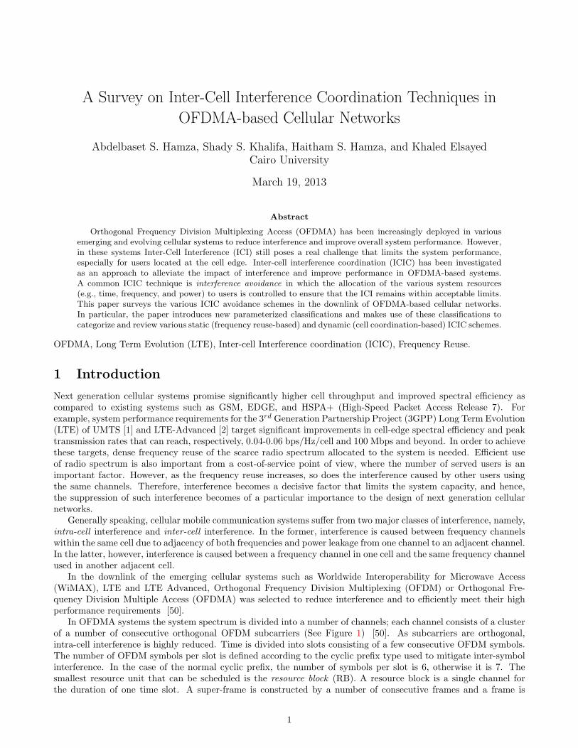
In OFDMA systems the system spectrum is divided into a number of channels; each channel consists of a clusterof a number of consecutive orthogonal OFDM subcarriers (See Figure 1) [50]. As subcarriers are orthogonal,intra-cell interference is highly reduced. Time is divided into slots consisting of a few consecutive OFDM symbols.The number of OFDM symbols per slot is defined according to the cyclic prefix type used to mitigate inter-symbolinterference. In the case of the normal cyclic prefix, the number of symbols per slot is 6, otherwise it is 7. Thesmallest resource unit that can be scheduled is the resource block (RB). A resource block is a single channel forthe duration of one time slot. A super-frame is constructed by a number of consecutive frames and a frame is
1
.. .
. . .
. . .
. . .
. . .
. . .
n /
Sig
na
lin
g C
ha
nn
el User 1
User 2
RBTime
Fre
qu
ency
Channel1
2
.. .
. . .
. . .
. . .
. . .
Bea
con
/ S
ig
User 3
Frame
Slot
N
1 2 t
Figure 1: Basic structure of frames in OFDMA Systems.
Interference Avoidance Schemes
Frequency Reuse-Based Schemes
Cell Coordination-Based Schemes
Conventional Frequency Reuse
Fractional Frequency Reuse ( FFR )
Centralized Autonomous Distributed
Semi Distributed
Coordinated Distributed
Reuse-1 Reuse-3 Partial Frequency
Reuse ( PFR )
Soft Frequency
Reuse ( SFR )
Intelligent Reuse
Figure 2: Inter-Cell Interference Avoidance Schemes.
2
constructed by a number of consecutive slots. Depending on the application, one or more RBs can be allocatedto a single user at a time. Each RB is assigned exclusively to one user at any time within a given cell; however,neighboring cells may reuse the same RB for different users.
In OFDMA systems, the transmission rate of a channel is variable and differs based on the user allocated tothis channel due to the use of Adaptive Modulation and Coding (AMC). Each enhanced NodeB (eNB) collects theChannel Quality Indicator (CQI) reports fed back from the users which are derived from the downlink receivedreference signal quality. The CQI is then used to determine the Modulation and Coding Scheme (MCS) for achannel. The modulation schemes ranges from the robust low rate QPSK scheme to the high rate but more errorprone 64-QAM scheme. Same MCS is used for all sub-carriers in a RB allocated for a given user though differentMCS can be allocated to different resource blocks [50]. The channel throughput is determined based on the usedMCS (selected based on the channel CQI reported from the user) which is mapped to the Transport Block Size(TBS) that can be used by using the mapping tables in [62]. Since different users perceive different channelqualities, a “bad” channel (due to deep fading and narrowband interference) for one user may still be favorableto other users. Thus, OFDMA exploits the multi-user diversity by avoiding assigning “bad” channels, which is animportant feature in OFDMA [30].
Even with almost no intra-cell interference, inter-cell interference (ICI) still presents a great challenge thatgreatly limits the system performance, especially for users located at the cell edge. In OFDMA systems, ICI iscaused by the collision between resource blocks [49]. With such collision model, the overall system performance isdetermined by the collision probabilities and the impact of a given collision on the Signal to Interference and NoiseRatio (SINR) associated with the colliding resource blocks. Inter-cell interference coordination (ICIC) mechanismsaim at reducing the collision probabilities and at mitigating the SINR degradation that such collisions may causein order to improve the system performance and increase the overall bit rates of the cell and its cell edge users.Generally speaking, ICIC techniques can be classified into mitigation and avoidance techniques.
In interference mitigation, techniques are employed to reduce the impact of interference during the transmissionor after the reception of the signal. In the literature [3]- [7], a wide range of techniques is presented in order toimprove the throughput of the cell-edge users by reducing or suppressing the ICI. Interference mitigation techniquesinclude [6]: (1) Interference randomization, where some cell-specific scrambling, interleaving, or frequency-hopping(spread spectrum) [6], (2) interference cancelation: where the interference signals are detected and subtracted fromthe desired received signal, or if multiple antenna system is employed, the receiver can select the best quality signalamong the various received signals [4], (3) adaptive beamforming: where the antenna can dynamically change itsradiation pattern depending on the interference levels.
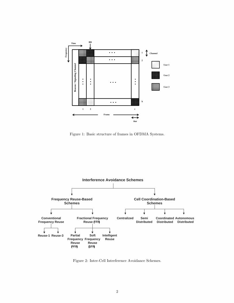
Interference avoidance schemes represent the frequency reuse planning algorithms used by the network elementsto restrict or allocate certain resources (in both frequency and time domains) and power levels among users indifferent cells. The objective of these frequency reuse planning algorithms is to increase the SINR, and hence, allowthe system to support as many users as possible. These frequency reuse planning algorithms must satisfy the powerconstraint in each cell by ensuring that the allocated transmission power of an eNB does not exceed the maximumallowable power. A fundamental concept common to most interference avoidance schemes is to classify users inthe cell based on their average SINR to a number of users’ classes (also known as “cell regions”). Interferenceavoidance schemes then apply different reuse factors to the frequency band used by the different classes of users(i.e, to different cell regions).
Various avoidance (allocation) techniques have been studied in the literature under various traffic conditions andnetwork structures. Schemes under this category can be classified along several orthogonal dimensions to mainlydifferentiate between static versus dynamic, and centralized versus distributed techniques. Moreover, avoidanceschemes differ with respect to the resources that are being allocated/ coordinated between users, and whethervarious power levels need to be used at different locations in the cell. Figure 2 depicts the various types ofinterference avoidance schemes.
In Static allocation schemes the resources allocated to each cell and users class are computed and evaluatedduring the radio planning process and only long-term readjustments are performed during the operation of thenetwork. Thus, the set of sub-carriers and the power levels allocated to each cell and user class is fixed (i.e static).Static allocation schemes are relatively easy to implement as they require no frequent interaction among involvedbase stations. However, since it is based on static frequency reuse, once this allocation scheme is used, it is not easyto perform modifications to the major frequency distributions [3]. Consequently, this scheme is not adaptive tomeet dynamic demand changes per sector as it adapts to the cell loads only by changing power used over differentsub-carriers. To confront this limitation, cell coordination based schemes were investigated, where coordinationamong neighboring base stations, on both sub-carriers and power levels is used. As a result, such schemes allow forefficient adaptation to the variations in cell loads.
3

1.1 Motivation and Scope
Motivated by the pressing need for developing high-speed high-performance cellular networks, the last few yearshave witnessed an increasing interest in the research community to develop various inter-cell interference avoidanceschemes for OFDMA-based cellular networks. As a result, several research papers have been published and, to thebest of our knowledge, there exists no comprehensive survey that investigates such a wide range of ICIC avoidanceschemes. Moreover, due to the large number of published work in this area, there have been several confusions andcontradictions between the various schemes either in their naming conventions or their operational principles. Thefollowing are some examples that can create such confusions:
• Some published work uses the notion of “Partial Frequency Reuse (PFR)” [12] while others use “FractionalFrequency Reuse with full isolation (FFR-FI)” [8] to refer to the same scheme.
• Some published work refers to the well known “Reuse-3” scheme as “Hard frequency reuse” [57].
• The notion of “Soft Frequency Reuse (SFR)” was originally proposed in [9] with a particular definition, whereasin [11] a different scheme was introduced with the same name of “Software Frequency Reuse (SFR)”.
In addition to the above, there has been a large number of approaches proposed for dynamic interference avoidance(e.g., power aware, fixed power, coordinated, distributed, autonomous, eNB initiated, UE initiated,etc.). Thesetechniques are difficult to comprehend and compare as they focus on the ICI problem from different perspectives.
Based on the above, we believe that there is a need for a survey to collate and present, in a systematic way, currentadvances in the area of ICIC. Moreover, we believe that such a survey should attempt to resolve the confusion andambiguity by providing a more precise classification criterion that does not depend merely on the traditional namingconvention that has been used so far in the research community. Accordingly, this paper surveys various techniquesproposed for static (frequency reuse based) as well as dynamic (coordination-based) inter-cell interference avoidanceschemes for the downlink of OFDMA-based cellular networks. In addition, the paper proposes novel parameterizedclassification approaches to express various static and dynamic avoidance schemes based on their structure andoperation in order to reduce ambiguity and increase understandability.
It is worth noting that, even though recent collaborative communications technologies, such as multi input multioutput (MIMO), coordinated multi-point (CoMP), and Relay transmission schemes, can contribute to the solutionof interference problem; however, these areas have wider scope and may require a separate focused survey, andhence, they are not included in the scope of this work.
1.2 Related Work
This section briefly reviews main survey papers related to interference avoidance schemes.In [57], Zhang proposed a classification for interference avoidance schemes with four categorizes. A scheme
is allocated to one of these four categories based on its degrees of freedom to adapt to network conditions. Theproposed four categories are:
• Static Schemes: where in design time, the best values for the different parameters (power ratio allocated to eachuser class, number of sub-bands allocated to each user class, frequency allocated to each cell) are determinedbased on full traffic load scenarios and then these values are kept fixed.
• Low level dynamic Schemes: As the best values for the different parameters may not always be “best” withdifferent traffic loads, Low level dynamic Schemes uses several pre-planned sets of best values for the differenttraffic loads and varied distributions of users. Given that base stations (BSs) can know the total number ofuser and there are reliable and efficient connections between BSs, a scheme can switch based on the traffic loadbetween two or more sets of best values each optimized for a certain traffic load.
• Intermediate level dynamic schemes: Given the serving-user’s quantity in each cell and locations of users in itsown cell data available to the BSs, BSs calculates the best values for the different parameters to escape thelimitation of using one of the pre-planned best value sets in Low level dynamic Schemes.
• High level dynamic schemes: Unlike the above categorizes that depend only on the user’s quantity, schemes inthis category require the availability of the channel condition information. High level dynamic schemes workssimilarly to Intermediate level dynamic schemes to calculate the best values for power ratio, the sub band numberand allocation of frequency but it also calculates the number of sub channel to be allocated to each user basedon its channel condition. However, there were no implementation or evaluation to High level dynamic schemesin the paper.
4

In his paper [57], Zhang only introduced the static interference avoidance schemes, provided no analysis oftheir performance and didn’t use the proposed categorizes to classify any of the published work. Regarding theproposed schemes classification, the analysis showed that as the degrees of freedom increases the total throughputand 10% throughput increase. However, while low level dynamic schemes and Intermediate level dynamic schemescan provide better performance than the Static schemes, they are not justified as nowadays users can send channelcondition reports to the base stations on regular relatively small intervals which makes High level dynamic schemesmuch more logical than both of them and so there would be no need for either the low level dynamic schemes orIntermediate level dynamic schemes.
Even though, multi-cell interference avoidance in OFDMA systems has been for a couple of year now a hotresearch area with a large number of recently published work, as far as we know, there are no published surveyscovering the multi-cell interference avoidance schemes in OFDMA systems. The only comprehensive survey that isrelated to this research area is the work published by Katzela et al. in 1996 [48], which surveys the various channelallocation schemes and a number of channel reuse schemes with limited focus on the ICI problem.
Katzela et al. in [48] classify the channel allocation schemes into the following three categories:
• Fixed Channel Allocation (FCA): In FCA, a set of nominal channels is permanently allocated to each cell for itsexclusive use. Where Channels can be allocated to cells either uniformly (equal shares) or nonuniformly (basedon expected traffic loads) with the option of allowing cells to borrow channels from one another.
• Dynamic Channel Allocation (DCA): In DCA, all channels are kept in a central pool and are assigned dynamicallyto cells when requested and then returned back to the central pool when became idle. The main idea of DCAschemes is to allocate a channel that minimizes the system cost provided that certain interference constraints aresatisfied. Based on information used for channel assignment, DCA schemes can be classified either as call-by-call(use only current channel usage conditions) or adaptive (use previous as well as current channel usage conditions).Based on the type of control employed, DCA schemes can be classified either as Centralized (a centralizedcontroller assigns channels to users) or Distributed (base stations assigns channels to users). Distributed DCAschemes can be either cell-based (base stations use local information collected from users and the exchangedinformation from other base stations) or adaptive (base stations rely only on the signal strength measurementscollected locally from its users).
• Hybrid Channel Allocation (HCA): HCA presents a mixture between FCA and DCA where the total number ofchannels available is divided into fixed and dynamic sets. The fixed set is assigned as in the FCA schemes whilethe dynamic set is shared by all cells.
The schemes covered in [48] were evaluated on multi-cell traditional cellular networks but not on OFDMAsystems which make the schemes doubtful to perform as stated in the survey when imported to any of the emergingOFDMA systems such as WiMAX, LTE or LTE-Adv [30]. This is due to several reasons. Firstly, unlike traditionalcellular networks that assumes a predetermined SINR threshold (for homogeneous applications such as voice),modern data networks utilize adaptive modulation which makes channel assignment decision non-binary from SINRstandpoint. UEs employ different modulation and coding schemes with different SINR, thus different throughputs(or achievable rates) are obtained at different SINR levels. Secondly, UEs are frequency selective and their data raterequirements are also different. Finally, the emerging OFDMA systems have put aggressive performance targetsthat were not planned for traditional cellular networks to handle. Emerging OFDMA systems have triggered anew wave of studies both within the academia and the industry for radio resource management in general andinterference coordination in particular that were not included in [48].
While our focus is on the downlink, Yaacoub et al. present in [18] a survey of resource allocation and schedulingschemes for the uplink channels in OFDMA wireless networks. As the main concern of this survey was resourcescheduling, single cell was considered most of the time while ICI in multi-cell scenarios was not heavily discussed.
In [42] Sadr et al. presented a survey on resource allocation algorithms for the downlink of multi-user ODFMsystem. However in this survey a single cell was assumed, thus inter-cell interference and inter-cell interferencecoordination for the downlink were not discussed.
1.3 Notations
Because various OFDMA-based cellular technologies make use of different terminologies and definitions for variouscomponents in the network, we unify these terminologies and use them throughout the paper to avoid confusionand improve clarity.
The term User Equipment (UE) is used to refer to the network end users. We use the term eNB to refer tothe network element used by the UEs to access the network. An eNB can be a Base Station (BS) or an Access
5
Point (AP). For the central entity controlling a number of eNBs, the term Radio Network Controller (RNC) isused. The term channel is used to indicate a resource unit to be assigned or restricted to users. A channel can bea resource block (RB), a sub-channel, sub-band, chunk, or a sub-carriers group. These terms will be usedthroughout the paper interchangeably.
The term cell and sector will be used interchangeably throughout the rest of the paper. Finally, The terminter-cell interference coordination (ICIC) schemes will be used throughout the rest of the paper to referto the interference avoidance schemes.
1.4 Paper Organization
The remainder of this paper is organized as follows. In Section II, a classification of frequency reuse-based schemesis presented and various schemes are explained. Section III presents a classification for various coordination-basedinterference avoidance schemes and explains some of these schemes. A discussion on future research directions ispresented in Section IV. Finally a summary is given in Section V.
2 Static ICIC: Frequency Reuse-based Schemes
One of the fundamental techniques to deal with the ICI problem is to control the use of frequencies over the variouschannels in the network. Frequency reuse-based schemes include: conventional frequency planning schemes (Reuse-1and Reuse-3), fractional frequency reuse (FFR), partial frequency reuse (PFR), and soft frequency reuse (SFR).
Despite their differences, all frequency reuse-based schemes need to specify: (1) the set of channels (sub-bands)that will be used in each sector/cell, (2) the power at which each channel is operating, and (3) the region of thesector/cell in which this set of channels are used (e.g., cell-centre or cell-edge). Different schemes define differentvalues and approaches for these various parameters.
Accordingly, we can identify a unified structured description for any frequency reuse-based scheme. We believethat such a structured description will not only simplify the expression of various schemes, but it will also reduceambiguity in understanding some of the subtle schemes reported in the literature. To this end, in the followingsubsections, we introduce a new classification model, and use this model to explain some of the key frequencyreuse-based schemes reported in the literature.
2.1 Definitions and Notation
The following are the basic parameters that we use to develop the proposed classification model.
• S = {s1, s2, s3}: the set of sectors per cell
• B = {B1, B2, ...., Bk}: the set of consecutive frequency bands that constitute the frequency spectrum in each cellsuch that Bi = (bi−1, bi], where bi refers to frequency i.
• R = {r1, r2, ...., rm} the set of co-centric rings that constitute the cell such that: ∀rj ∈ R, j > 1, rj represents aring that is bounded between the two radii ρj−1, ρj . A ring rj defines a user class (center, edge, ...) that can beallocated to a set of specified channels. While ρj defines the threshold after which a user is not classified as rj .For j = 1, rj represents the cell center users.
• α = {a1, ..., an}: the set of ascending power levels used within the sub-bands of a cell with respect to the maximumavailable power in the system. That is, az ∈ α = Pz
Pmax, where Pz is the power level used in a particular sub-band,
and Pmax is the maximum power used in the system. A sub-band that is not used in a particular cell will beassigned a power level 0.
A particular frequency reuse-based scheme can be described by defining the cardinality and elements of theabove parameters, then, each sector/cell,si ∈ S, can be expressed as follows:
si = {Bk(an, rm) : 1 ≤ k ≤ |B|; an ∈ α; r ∈ R}
6

B1
B1
B1
B1
B2
B3
a1
a1
a1
a1
a1
a1
a1
Power
Power
r1
r1
r1
r1
r1
r1
Figure 3: Conventional Frequency Planning (a) Reuse-1 (b) Reuse-3.
2.2 Conventional Frequency Planning
The simplest scheme to allocate frequencies in a cellular network is to use a frequency reuse factor (FRF) of 1, thatis, all available frequency spectrum is reused in each sector without imposing any restrictions on frequency resourceusage or power allocation [Figure 3-(a)]. The reuse-1 scheme can be described as follows: B = {B1}, R = {r1},and α = {a1}. The three sectors are identical, hence:
s1 = s2 = s3 = {B1(a1, r1)}.Apparently, this scheme allows for achieving the high peak data rate. However, this comes at the cost of
suffering the worst case inter-cell interference levels, especially for cell edge users. This in turn, will greatly limitthe performance of these users, leading to an overall lower spectral efficiency.
To reduce the ICI level resulted in the reuse-1 scheme above, the whole frequency band can be divided into threeequal but orthogonal sub-bands. Adjacent sectors will be allocated different sub-bands [Figure 3-(b)]. This schemeis known as reuse-3, and it can be described as follows: B = {B1, B2, B3}, R = {r1}, α = {a1}. Accordingly, thethree sectors of this scheme can be expressed as follows:
s1 = {B1(0, 0), B2(0, 0), B3(a1, r1)}s2 = {B1(0, 0), B2(a1, r1), B3(0, 0)}s3 = {B1(a1, r1), B2(0, 0), B3(0, 0)}This clustering obviously leads to an improved (lower) inter-cell interference; however, this comes at the cost of
very low bandwidth utilization due to the restrictions imposed on the reuse of the available resources. In fact, onlyone third of the resources are utilized in each sector.
It appears from the above discussion that conventional frequency planning schemes represent the lower andupper bounds on the interference as well as resource utilization in the network. While reuse 1 does not employany interference coordination, reuse 3 can be regarded as an extreme case of partition based static interferencecoordination.
2.3 Fractional Frequency Reuse (FFR)
To avoid the shortcomings of the conventional frequency reuse schemes, the fractional frequency reuse (FFR) schemeis introduced to achieve a FRF between 1 and 3. FFR divides the whole available resources into two subsets orgroups, namely, the major group and the minor group. The former is used to serve the cell-edge users, while thelatter is used to cover the cell-center users. Generally speaking, the FFR scheme can be divided into three mainclasses:
7

B1
B1
B1 B2
B3
B4
a1
a1
a1
a2
a2
a2
Power
r1
r1
r1
r2
r2
r2
Figure 4: Fractional Frequency Reuse with Full Isolation (FFR-FI).
1. Partial Frequency Reuse (PFR) Schemes: in these schemes a common frequency band is used in all sectors (i.e.,with a frequency reuse-1) with equal power, while the power allocation of the remaining sub-bands is coordinatedamong the neighboring cells in order to create one sub-band with a low inter-cell interference level in each sector.
2. Soft Frequency Reuse (SFR) Schemes: in these schemes, each sector transmits in the whole frequency band.However, the sector uses full power in some frequency sub-bands while reduced power is used in the rest of thefrequency band.
3. Intelligent Reuse Schemes: in these schemes, band allocated to different sectors expands and dilates based onthe existing workloads. These schemes start with a reuse-3 like configuration at low workloads which can bechanged with the increase of workloads to become PFR, SFR or even reuse-1.
In [10] a study that attempts to find an optimum FFR is presented where the problem is formulated as sum-power minimization problem subject to minimum rate constraints in both the regions. The study considers theoptimal FFR factor for the cell-edge region, bandwidth assigned to each region and subcarrier and power allocationto all the users in the cell. The key result is that for the same minimum demanded rate for all users, it is foundthat the power consumed is minimal when the reuse factor used for the cell-edge region is 3. In the following, adetailed discussion of different frequency reuse schemes is presented.
2.3.1 Partial Frequency Reuse (PFR)
From the above discussion, it is clear that using the same FRF value for the entire cell is not bandwidth-efficient [8].One way to improve the cell-edge SINR, while maintaining a good spectral efficiency, is to use an FRF greater thanunity for the cell-edge regions and an FRF of unity for the cell-center regions [11]. In a homogeneous network, thecell centre regions have equal areas.
The idea of the partial frequency reuse (PFR) is to restrict portion of the resources so that some frequenciesare not used in some sectors at all. The effective reuse factor of this scheme depends on the fraction of unusedfrequency [12].
The PFR is also known as FFR with full isolation (FFR-FI), as users at cell-edge are fully protected (isolated)from adjacent cells’ interference [8]. An example for sites with 3 sectors is shown in Figure 4. The effective reuseof PFR is greater than one. To see this, consider a system with available bandwidth equal to β. This bandwidth isdivided into inner and outer zones with bandwidth equal to βi and β0, respectively. Band βi is used with a reusefactor of 1, and for the tri-sector BSs, the reuse factor for β0 is usually 3 in the outer zone. In this case, the effectivefrequency reuse factor is given by β/(βi + (β0/3)). Therefore, the effective reuse of PFR scheme is always greaterthan 1 [12].
This scheme can be described as follows: B = {B1, B2, B3, B4}, R = {r1, r2}, α = {a1, a2}. Accordingly, thethree sectors of this scheme can be expressed as follows:
s1 = {B1(a1, r1), B2(0, 0), B3(0, 0), B4(a2, r2)}s2 = {B1(a1, r1), B2(0, 0), B3(a2, r2), B4(0, 0)}
8

B1
B1
B1 B2 B4
B3
B2B3
B4
a1
a1
a2
a2
a2
a1P
ower
r1
r1
r1
r2
r2
r2
r2
r2
r2
Figure 5: PFR with only one interference in the worst case.
s3 = {B1(a1, r1), B2(a2, r2), B3(0, 0), B4(0, 0)}A numerical method for calculation of interference generated by co-channel cells is proposed and discussed
in [13] [14]. The level of co-channel interference in three different scenarios is compared, in particular, cellularsystem with universal frequency reuse, cellular system with reuse-3 and cellular system with implemented ICICbased on fractional frequency reuse. Analysis shows that the interference experienced by users in their own cells isalmost two times smaller when using fractional frequency reuse instead of frequency reuse factor 3 and approximatelythree times smaller than universal frequency reuse case.
A novel fractional frequency reuse scheme combined with interference suppression for orthogonal frequencydivision multiple access (OFDMA) networks is introduced in [20]. The PFR with only one interference in theworst case scheme (Figure 5) ensures maximum of one-type interferer, that is only users in the neighboring cellsusing the same band will cause interference to the cell edge users, and hence, it was possible to suppress thisinterference by using interference exploitation techniques. Results indicate a reduction in power at no cost ofincreased complexity. This FFR scheme can be classified as a variation of the PFR scheme, and it can be describedas follows: B = {B1, B2, B3, B4}, R = {r1, r2}, α = {a1, a2}. Accordingly, the three sectors of this scheme can beexpressed as follows:
s1 = {B1(a1, r1), B2(a2, r2), B3(0, 0), B4(a2, r2)}s2 = {B1(a1, r1), B2(0, 0), B3(a2, r2), B4(a2, r2)}s3 = {B1(a1, r1), B2(a2, r2), B3(a2, r2), B4(0, 0)}
2.3.2 Soft Frequency Reuse (SFR)
The PFR scheme may result in under-utilization of available frequency resources due to its strict no-sharing policy.Soft Frequency Reuse (SFR) was proposed in [5] [9] to present a balance between the FRF and the PFR schemes. Itavoids the high ICI levels associated with the unity FRF configurations, while providing more flexibility to the PFRscheme. The term soft reuse is due to the fact that effective reuse of the scheme can be adjusted by the division ofpowers between the frequencies used in the centre and edge bands.
SFR makes use of the concept of zone-based reuse factors in the cell-center and cell-edge areas. Unlike the PFR;however, frequency and power used in these zones are restricted. In particular, a frequency reuse factor of 1 isemployed in the central region of a cell, while frequency reuse factor greater than 1 at the outer region of the cellclose to the cell edge.
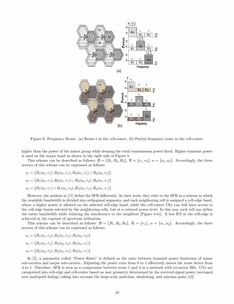
For example, consider the 3-sector cell sites shown in Figure 6, the cell-edge band (major band) uses 1/3 ofthe available spectrum which is orthogonal to those in the neighboring cells and forms a structure of cluster sizeof 3. The cell-centre band (minor band) in any sector is composed of the frequencies used in the outer zone ofneighboring sectors. According to the original contribution in which the SFR is proposed [9], the major band canbe used in the cell-centre as well if it is not occupied by the cell-edge UEs, resulting in a frequency reuse factor of1 for the inner part of the cell, but the minor band is available to the centre area only [Figure 6-a)]. Each groupis assigned transmission power depending on the desired effective reuse factor, such that the major band group is
9
(a)
(b)
r1r1
r1 r1
r1r1
B1 B2
B2
B2
B1
B1B3
B3
B3
a1
a1
a1
a2
a2
a2
Power
r1 @ a1
r2 @ a2
r1 @ a1
r2 @ a2
r1 @ a1
r2 @ a2
B1
B1
B1
B2
B2
B2
B3
B3
B3a1
a1
a1
a2
a2
a2
Power
r1r1
r1 r1
r1 r1
r2
r2
r2
Figure 6: Frequency Reuse: (a) Reuse-1 in the cell-centre, (b) Partial frequency reuse in the cell-centre.
higher than the power of the minor group while keeping the total transmission power fixed. Higher transmit poweris used on the major band as shown in the right side of Figure 6.
This scheme can be described as follows: B = {B1, B2, B3}, R = {r1, r2}, α = {a1, a2}. Accordingly, the threesectors of this scheme can be expressed as follows:
s1 = {B1(a1, r1), B2(a1, r1), B3(a1, r1) ∪B3(a2, r2)}s2 = {B1(a1, r1), B2(a1, r1) ∪B2(a2, r2), B3(a1, r1)}s3 = {B1(a1, r1) ∪B1(a2, r2), B2(a1, r1), B3(a1, r1)}However, the authors in [11] define the SFR differently. In their work, they refer to the SFR as a scheme in which
the available bandwidth is divided into orthogonal segments, and each neighboring cell is assigned a cell-edge band,where a higher power is allowed on the selected cell-edge band, while the cell-centre UEs can still have access tothe cell-edge bands selected by the neighboring cells, but at a reduced power level. In this way, each cell can utilizethe entire bandwidth while reducing the interference to the neighbors [Figure 6-b)]. A less ICI at the cell-edge isachieved at the expense of spectrum utilization.
This scheme can be described as follows: B = {B1, B2, B3}, R = {r1}, α = {a1, a2}. Accordingly, the threesectors of this scheme can be expressed as follows:
s1 = {B1(a1, r1), B2(a1, r1), B3(a2, r2)}s2 = {B1(a1, r1), B2(a2, r2), B3(a1, r1)}s3 = {B1(a2, r2), B2(a1, r1), B3(a1, r1)}In [5], a parameter called “Power Ratio” is defined as the ratio between transmit power limitation of minor
sub-carriers and major sub-carriers. Adjusting the power ratio from 0 to 1 effectively moves the reuse factor from3 to 1. Therefore, SFR is seen as a compromise between reuse 1 and 3 in a network with tri-sector BSs. UTs arecategorized into cell-edge and cell-centre based on user geometry determined by the received signal power (averagedover multipath fading) taking into account the large-scale path-loss, shadowing, and antenna gains [12].
10
Power
B1
B1
B1
B2
B2
B2B3
B3
B3B4
B4
B4a1
a1
a1
a2
a2
a2
r1 r
1r1
r1
r1
r1
r1 r
1 r1
r2
r2
r2
Figure 7: Soft Fractional Frequency Reuse (SFFR).
Simulation results reported in [5] [9] show that: if the power ratio equals one (i.e., major and minor subcarriersare given same power), the cell-edge bit rate equals one third of the cell-edge bit rate in case of the universal reusefactor (i.e., reuse-1). As the power factor decreases towards 0, the total cell throughput decreases as well. Also, thethroughput of the inner zone decreases as well. However, the cell-edge throughput increases due to the increasingtransmission power for cell-edge users and the mitigation of co-channel interference. The above discussion can leadto the general conclusion that the SFR scheme can improve the SINR of the cell-edge UEs using a greater thanunity FRF, while degrading the SINR of the cell-centre UEs. This degradation is due to the overlap in frequencyresources between the cell-edge band of the neighboring cells, and the cell-centre band of the serving cell. However,as the ICI is not as dominant and important for the cell-centre UEs as for the cell-edge UEs, and since a cell-centerUEs SINR is typically much higher than unity, the cell-centre UEs spectral efficiency increases only logarithmicallywith SINR. However, for the cell-edge UEs with SINR value much less than unity, the spectral efficiency increasesalmost linearly with SINR. This leads to a cell-edge performance improvement almost linear with SINR while thedegradation to the cell-centre UEs is logarithmic with SINR. In SFR, the power ratio between the cell-edge bandand the cell-centre band can be an operator-defined parameter, thereby increasing the flexibility in system tuning.
In [15], the performance of the SFR with partial frequency reuse at the cell centre for large scale networksin realistic radio environments and with irregular cell patterns is investigated. According to simulations, two keyconclusions are drawn. SFR’s parameters have to be carefully selected and optimized since any improvement forthe cell edge users comes at the expense of performance of the cell centre users. Therefore, it was suggested thatthe SFR is better used for resolving interference issues at some specific areas, at which the performance reductionat the center zones is much significant compared to the improvement in the cell edge, rather than being used in theentire network. It is also found that the cell-edge performance is sensitive to the bandwidth allocated; an interestingresult is that the two sub-bands have better performance over the conventional three sub-bands. A recommendationfor further work is then presented for performing comparison studies between the SFR scheme and other schemes.Also, the usage sub-bands of unequal sizes is recommended. This can better adapt the reuse pattern to the celllayout.
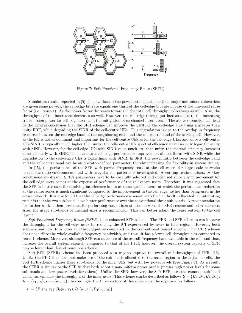
Soft Fractional Frequency Reuse (SFFR) is an enhanced SFR scheme. The PFR and SFR schemes can improvethe throughput for the cell-edge users by reducing the ICI experienced by users in that region. However, bothschemes may lead to a lower cell throughput as compared to the conventional reuse-1 scheme. The PFR schemedoes not utilize the whole available frequency bandwidth, and thus, it has a lower cell throughput as compared toreuse-1 scheme. Moreover, although SFR can make use of the overall frequency band available in the cell, and thus,increase the overall system capacity compared to that of the PFR; however, the overall system capacity of SFRmaybe lower than that of reuse one scheme.
Soft FFR (SFFR) scheme has been proposed as a way to improve the overall cell throughput of FFR [16].Unlike the PFR that does not make use of the sub-bands allocated to the outer region in the adjacent cells, theSoft FFR scheme utilizes these sub-bands for the inner UEs, but with low power levels (See Figure 7). As a result,the SFFR is similar to the SFR in that both adopt a non-uniform power profile (it uses high power levels for somesub-bands and low power levels for others). Unlike the SFR; however, the Soft FFR uses the common sub-bandwhich can enhance the throughput of the inner users. This scheme can be described as follows:B = {B1, B2, B3, B4},R = {r1, r2}, α = {a1, a2}. Accordingly, the three sectors of this scheme can be expressed as follows:
s1 = {B1(a1, r1), B2(a1, r1), B3(a1, r1), B4(a2, r2)}
11

a1
a1
a1
a2
a2
a2
a3
a3
a3
B1
B1
B1
B2
B2
B2
B3
B3
B3
Power
r1
r1
r1
r2
r2
r2
r3
r3
r3
Figure 8: FFR with multiple user class.
s2 = {B1(a1, r1), B2(a1, r1), B3(a2, r2), B4(a1, r1)}s3 = {B1(a1, r1), B2(a2, r2), B3(a1, r1), B4(a1, r1)}In [17], several variations of the power profile used in the Soft FFR scheme are investigated. Several interesting
observations were presented and can be summarized as follows:
• Transmission power level of the common part does not have a significant influence on the overall cell throughput.Accordingly, the total transmission power used in the cell can be reduced by minimizing the power level of thiscommon part without impacting the required cell throughput level.
• Transmission power level in the outer region has a direct impact on the throughput of that region. In particular,it was observed that the throughput of this region is directly proportional to its power, and inversely proportionalto the inner region’s throughput. As a result, according to the throughput requirements in the outer region, thepower consumption for the outer region can be reduced, while maintaining high overall system throughput.
Downlinks transmit power allocation in soft FFR under two different coordination cases, namely; loosely andtightly coordinated cells are studied [19]. In the loosely coordinated cells case, the sub-band transmit powersare allocated so that the cell edge user meets the required throughput. The loss in average cell throughput canbe reduced by configuring appropriate number of sub-bands for inner and outer regions. However, in the tightlycoordinated cells, sub-band power allocation can be changed packet by packet in each scheduling period. It isfound that in this cell coordination case, the loss of spectral efficiency can be minimized regardless of the numberof sub-bands due to its fast coordination.
A FFR with multiple user class scheme that deals with different user classes is presented in [21] [22]. Thescheme uses an approach similar to that of the PFR with only one interference in the worst case scheme [20]where cells are divided into a number of concentric zones, each with a different frequency reuse factors as illustrated(Figure 8). However, unlike the PFR with only one interference in the worst case scheme where some bands arerestricted, under this scheme, the cell uses the entire band but under different power level restrictions based on thetype of UEs. Central UEs are served first with the low power sub-band (if this is not enough, next sub-bands canbe used, but should still maintain the low power level). Next, intermediate and finally cell edge UEs are served withthe same criterion. This scheme can be described as follows: B = {B1, B2, B3}, R = {r1, r2, r3}, α = {a1, a2, a3}.Accordingly, the three sectors of this scheme can be expressed as follows:
s1 = {B1(a3, r3), B2(a1, r1), B3(a2, r2)}s2 = {B1(a2, r2), B2(a3, r3), B3(a1, r1)}s3 = {B1(a1, r1), B2(a2, r2), B3(a3, r3)}
2.3.3 Intelligent Reuse
Incremental Frequency Reuse (IFR): Under the SFR scheme, cell edge users have a maximum of one third of theentire bandwidth to utilize. However; typically, cellular systems have more cell edge users than cell center users.
12

Figure 9: Low spectrum efficiency problem in SFR.
Thus, SFR may result in low spectrum efficiency. Moreover, as shown in Figure 9, under the SFR scheme, co-channel interferences may increase even under low traffic load situation, while there are still sub-channels in idleand underutilized in the system. This is due to the fact that resource allocation of all cells under the SFR schemestarts always from the first sub-channel up. Again, this may reduce the spectrum utilization efficiency.
In addition, results on the usage of SFR showed that the cell throughput is even lower to the conventionalreuse-1 scheme when loading factor is over 0.5 [23]. This is because under the SFR scheme, at most one third ofthe sub-channels can be used to transmit data with higher power while the remaining two third sub-channels workwith lower power, which induces an overall throughput loss. Thus, the SFR ameliorates performance of the celledge users at the expense of degrading the overall cell capacity [24].
In order to overcome some of the shortcomings of the conventional SFR scheme discussed above (low spectrumefficiency, increased co-channel interferences at low loading traffic, and loss of cell capacity system when system isover half-full loaded), in [23], Kim et al. proposed the concept of Incremental Frequency Reuse (IFR) scheme. IFRattempts to reduce the ICI effectively under low offered traffic, while maintaining the overall system capacity.
Figure 10 illustrates the basic concept of the IFR scheme in a tri-sector cell system with 3 various typesof neighboring cells. The only difference between the IFR and the classical reuse-1 is, from which point of theavailable bandwidth it starts dispensing resources to the users. In an IFR system the directly adjoining cells assignresources from different sub-channels. Cells of type-A occupy resources from the first sub-channel, whereas cells oftype-B from one third of the whole bandwidth, and cells of type-C from two third of the bandwidth. They allocateconsecutive sub-channels successively along with traffic load increasing until the entire bandwidth is used up. TheICI generated by directly adjoining cells can be avoided completely at low traffic situation, since frequency reuseof the first tier neighboring cells doesn’t occur when loading factor below 0.3, and the whole system operates as inthe classical reuse-3 system. Effectively, under the IFR scheme, the system operates with increasing traffic load likemoving from a reuse-3 system to a reuse-1 system.
Despite the fact that the IFR scheme can overcome most of the limitations inherited in the SFR scheme;however, the IFR scheme performs better only under low traffic. When the loading factor in the system is above0.3, the IFR performance is lower than that of the SFR. Simulation results reported in [23]concluded that both theIFR and the SFR schemes do not perform better than the classical reuse-1 scheme in over-middle-load or full-loadsituations. For IFR, all bandwidth becomes available to all cells resulting in an overall cell capacity equals to thatof reuse-1. The SFR scheme performs worse than reuse-1 as two-thirds of the users are allocated to the secondary-band achieving relatively lower throughputs due to the limited transmit power, while only one-third achievinghigher throughput. Accordingly, it is concluded that the system capacity cannot be substantively improved by theIFR and the SFR schemes. This scheme can be described as follows: B = {B1, B2, B3}, R = {r1}, α = {a1}.Accordingly, the three sectors of this scheme can be expressed as follows:
s1 = {B1(a1, r1), B2(a1, r1), B3(a1, r1)}s2 = {B2(a1, r1), B3(a1, r1), B1(a1, r1)}
13

Start point of subchannel allocation
A
C C
C
B B
B
5
f
A
2 3 4 6 7 8 9
2 7
f
B
8 9 1 3 4 5 6
8 4
f
C
5 6 7 9 2 3 1
1
Figure 10: IFR scheme in a tri-sector cell system.
Primary Segment Idle subchannel
Reuse-3 subchannel for each type of cell F2 + F3 + F5 + F6 + F8 + F9
F 5
f
A F 2 F 3 F 6 F 8 F 9
F 1
F 5
f
B F 2 F 3
F 4 F 6 F 8 F 9
F 5
f
C F 2 F 3 F 6 F 8 F 9 F 7
B
A
C
B
C
B
C
F 1 F 4 F 7
Figure 11: Enhanced Fractional Frequency Reuse (EFFR) .
s3 = {B3(a1, r1), B1(a1, r1), B2(a1, r1)}Enhanced Fractional Frequency Reuse (EFFR): To further improve the performance of the IFR and the SFR
schemes and overcome their limitations, a scheme called Enhanced Fractional Frequency Reuse (EFFR) was pro-posed in [24]. EFFR attempts to enhance the system capacity especially under overload situations.
Similar to the IFR scheme, the EFFR scheme defines 3 cell-types for directly neighboring cells in a cellularsystem, and reserves for each cell-type a part of the whole frequency band named Primary Segment, which is shownin the right part of Figure 11 with thick border.
The Primary Segments among different type cells should be orthogonal. The remaining sub-channels excludingthe Primary segments constitute the Secondary Segment. The Primary Segment of a cell-type is at the same timea part of the Secondary Segments belonging to the other two cell-types. Each cell can occupy all sub-channels ofits Primary Segment at will, whereas only a part of sub-channels in the Secondary Segment can be used by this cellin interference-aware manner.
The Primary Segment of each cell will be further divided into a reuse-3 part and reuse-1 part. The reuse-1part can be reused by all types of cells, while reuse-3 part can only exclusively be reused by other same type cells.The reuse-3 sub-channels cannot be reused by directly neighboring cells, that attenuates the co-channel interferencesamong them and therefore it is specified for the vulnerable cell edge users to take priority of using these sub-channelsover cell center users.
Since a cell acts on the Secondary Segment as a guest, and occupying secondary sub-channels actually reusesthe primary sub-channels belonging to the directly neighboring cells, therefore, the Secondary Segment to be reusedshould be first monitored, then being reused based on the SINR estimation.
Each cell listens on every secondary sub-channel all the time. And before occupation, it makes SINRevaluation according to the gathered channel quality information (CQI) and chooses resources with best estimationvalue for reuse. If all available secondary resources are either occupied or not good enough to a link, it will give upreusing for this link. This will not lead to resource wasting, which means some resources maybe not reusable forthis link, but can be reused by other links. Another gained merit is that it will not generate excessive interferencefor the neighboring cells which would degrade their performance. So, an upgrade of spectrum efficiency is expectedby using the interference-aware-reuse mechanism on the Secondary Segment.
Simulation results for comparing the EFFR scheme with conventional reuse-1, reuse-3, and the IFR schemes
14
show a significant improvement in the overall capacity gains at cell edge as compared to other schemes. This schemecan be described as follows: B = {B1, B2, B3, B4, B5, B6}, R = {r1, r2}, α = {a1, a2}. Accordingly, the three sectorsof this scheme can be expressed as follows:
s1 = {B1(a2, r2), B2(a1, r1), B3(0, 0), B4(a1, r1), B5(0, 0), B6(a1, r1)}s2 = {B1(0, 0), B2(a1, r1), B3(a2, r2), B4(a1, r1), B5(0, 0), B6(a1, r1)}s3 = {B1(0, 0), B2(a1, r1), B3(0, 0), B4(a1, r1), B5(a2, r2), B6(a1, r1)}Combined Partial Reuse and Soft Handover: An interesting ICIC scheme that employs both partial frequency
reuse (PFR) and soft handover (SH) is proposed in [25]. This proposed scheme differentiates between the cellinterior users (CIUs) from the cell edge users (CEUs) using the soft-handover (SH), where a user is considered as acell edge user if there is at least two cells in its handover list, accordingly the user is allocated one of the sub-channelsthat are designed to serve this region of the cell. Effectively, this scheme capitalizes on the information alreadyavailable from the handover algorithm, and thus, it eliminates the complexity of geometry determination based onthe duplicate calculation of SINR. In addition, it eliminates the need for extra signaling. Simulation results reportedin [25] shows that the combined approach can provide a significant cell edge throughput gain over the conventionalpartial frequency reuse scheme. In addition, this scheme is shown to have a low soft handover overhead.
Table 1 summarizes the various frequency reuse-based schemes using the above classification parameters.
2.4 Comments on Frequency Reuse-Based ICIC Schemes
In [55] and [56], Gonzalez et al. conducted a comparison among a number of static schemes to evaluate theperformance of static ICIC schemes in regular cells and realistic irregular cells layouts.
In [55], three static ICIC schemes (PFR [11] Figure 6-(b), FFR with multiple user class [21] Figure 8 andFFR-FI [8] Figure 4) were compared in a regular cells layout. The role of the different elements affecting theirspectral efficiency versus fairness tradeoff was investigated. These elements are:
(1) Threshold to classify users (ρj) which can be either Class Proportionality where the SINR thresholds areselected so that each class has the same average number of users or Bandwidth Proportionality where the SINRthresholds guarantee that the number of users is proportional to its allocated bandwidth.
(2) Effect of the power level allocated to different user classes (α).
(3) Effect of the number of user groups (R) which in turn reflect the effect of the size of the bandwidth allocatedto each user group (B). With the increase of the number of user groups, the bandwidth allocated to each usergroup tends to decrease.
(4) Effect of inter-class interference which is caused due to using the same band for different user classes at thedifferent cells. Restricting inter-class interference would mean using a reuse-n where n ≥ 3 for the edge bands asin FFR-FI scheme [8]. Center-users receive ICI of types inter-class (coming from users of different classes (i.eedge users) using the same band in the neighboring cells) and intra-class (coming from users of the same class(i.e center users) using the same band in the neighboring cells). Edge users only receive inter-class interference.
Based on their findings, Gonzalez et al. provided the following recommendations:
• The choice of the threshold to classify users (ρj) has an immediate impact on the scheduler decisions and soon the system performance. When bandwidth proportionality is used, the set of cell-edge users becomes smallerleaving more Resource Blocks (RBs) for them to use than the class proportionality case leading to a slightly betterfairness value. On the other hand, class proportionality brings a significant spectral efficiency improvement atthe expense of a small fairness degradation.
• Regarding the effect of the power level allocated to different user classes (α), it was found that an increase inthe power allocated to center-users leads to better values of efficiency no matter which threshold to classify userscriterion has been selected. The higher the difference in the power assigned to the different user classes, thehigher value of fairness and the lower value of efficiency. The reason behind this behavior is that given that thebandwidth assigned to each class is fixed, having a small difference in the power assigned to the different userclasses causes the energy previously assigned to the users having worse channel to move to users with betterchannel conditions.
15

• For the effect of the number of user groups (R), the analysis showed that as users are grouped into more classes,fairness is improved. Nevertheless, smaller number of user groups increases the spectral efficiency since theallocation of a wider band to the set of users enjoying a better radio channel becomes the predominant effect,especially when the SINR threshold is shifted to higher values.
• The inter-class interference can be completely removed but at the expense of a reduction in the available band-width at each cell as it can be seen in Figure 4. The advantage of doing so is that higher levels of SINR can beachieved for edge users within the cell as no other cell is using the same band. On the other hand, the reduction inthe bandwidth causes a reduction in terms of spectral efficiency. However, the effectiveness in the use of resourcesis higher compared to schemes with inter-class interference indicated by high values of bits per RB and bits perWatt.
In [56], Gonzalez et al. extended their evaluation of static schemes by a comparative study of the performanceof four ICIC schemes (reuse-1 Figure 3-(a), reuse-3 Figure 3-(b), SFR [9] Figure 6-(a), FFR-FI [8] Figure 4) in arealistic non-regular cellular layout giving special attention to the efficiency vs. fairness tradeoff. The evaluationscenarios simulated the city of Vienna and its surroundings using the digital elevation model, system layout andpropagation data provided by the MORANS initiative [58] which was framed within the European COST 273 Actionto provide common system simulation environments so that different researchers can compare results. However,we failed to get such scenario data sets or access the related documentation as they seem have been restricted forpublic access. Another openly available alternative for real life cellular layouts is the network planning scenariosfor Berlin and Lisbon provided by the European Momentum project [59] which contains the city’s realistic radiopropagation setting. The Momentum project data sets were used in [15] to evaluate the performance of SFR inlarge networks with irregular cell patterns.
Comparing the scheme’s evaluation in realistic irregular cells conducted in [56] to the evaluation conducted onregular shaped cells in [55] led to the following conclusions:
• Regarding the effect of the power level allocated to different user classes, the same behavior remains in realisticlayouts where an increase in the power allocated to center-users leads to better values of efficiency and lowervalues of fairness. Also, the higher the difference in the power assigned to the different user classes, the highervalue of fairness and the lower value of efficiency.
• The effect of the number of user groups in realistic scenarios increases on all performance metrics due to theirregular geometry.
• Also, as users are grouped into less classes, the effect of the power level allocated to different user classes increaseson all metrics.
In their study, Gonzalez et al. concluded that the best performance cannot be obtained by applying traditionalICIC schemes [56]. The optimal settings for ICIC are particular to each geometry and the performance of staticICIC schemes is different from one network to another. Static ICIC schemes could penalize cells receiving moreinterference due to irregular cell layouts and thus irregular cell layouts require non-regular bandwidth allocationsthat suites each cell geometry. Furthermore, static schemes are unsuitable for Heterogeneous Networks (HetNets)with femto/pico/macro cells as these cells are placed at the end-user’s locations in an ad-hoc manner makingany prior frequency planning difficult [12]. These shortcomings of static schemes are addressed by dynamic ICICschemes as they do not require prior frequency planning and operate based on dynamic interference informationfrom surrounding transmitters.
3 Dynamic ICIC: Cell Coordination-based Schemes
The scale and complexity of modern mobile communication systems have motivated the exploration of cell coordination-based schemes as possible models for management and control of such highly complex systems [61]. The complexityof these systems is due to several factors including the diversity of applications, volume of connections, geographicspread of users, localized ownership of the network, and “connectivity, anytime, anywhere” with an ever increasingdemand for bandwidth.
The issue with the apriori frequency planning schemes discussed in Section II is that the inhomogeneous trafficload and varying user group distribution within each cell is ignored to simplify the cell-planning phase. Thisconsequently leads to significant performance degradation in terms of cell and user throughput [33]. In realisticsystems, the traffic load is unlikely to be spatially homogeneous and may exhibit significant variations over time.
16

For example, one might see concentrations of users in different regions at different times of the day, e.g, trainstations, shopping districts, and lunch time. As such, it is crucial that interference coordination schemes should bedesigned to adapt to different network interference conditions, user traffic load, and user distribution in order tomaximize the total network throughput.
Cell coordination schemes have emerged as an efficient solution to cope with the continuous dynamic traffic loadchanges in cells. In cell coordination, interference reduction is realized by real time coordination using adaptivealgorithms to efficiently manage the resource utilization among cells without apriori resource partitioning.
Although this solution presents a flexible framework as no apriori frequency planning is required, it may howeverrequire a signaling interface between different eNBs in order to achieve the required coordination which is consideredas a serious complexity with respect to both overhead and delay. Various cell coordination-based schemes presenttrade-offs between implementation complexity and the overhead of signaling. The problem of resource allocationwith dynamic demand is known to be NP-hard [31]. Using an exact method is computationally inefficient as theproblem involves extremely large search spaces with correspondingly large number of potential solutions. As the newresources configurations must be computed at run-time, computational efficiency is favored over model accuracy.
Due to the complexity of the dynamic ICIC problem, most of the performance evaluations are based on simulationmodels. A principal problem with simulation evaluations during comparing different schemes is the lack of commoncontext, scenarios and evaluation metrics. Thus, unified realistic scenario data sets are needed that define commonconditions such as cells layout, number of channels, propagation data and traffic intensity as well as a unified setof metrics to be used to evaluate various approaches. This issue has been open since 1996 [48]. There were someinitiatives (e.g., [59]) to provide a realistic common context and scenario data sets. However, these initiatives didnot receive enough attention in the community, and thus, the challenge of performance comparison for dynamicICIC still remains. Accordingly, comparison of the permeance of various scheme may not be accurate enough, andhence, in this work, we base our review for the various schemes on the advantages and disadvantages, computationalcomplexity, signalling overhead, and practicality of implementation.
In this section, a new classification model is presented and used to classify and explain various coordination-basedschemes. The proposed classification model makes use of four dimensions, namely, the optimization objective, powercontrol technique, channel allocation recommender, and the fairness to UE. In the following, the four classificationdimensions are explained and then used to review key coordination-based schemes reported in the literature.
3.1 Classification of Coordination-based ICIC Schemes
Coordination-based schemes can be categorized, based on the level of coordination, into four main categorizes:centralized, semi-distributed, coordinated-distributed, and autonomous-distributed. In addition to these levels ofcoordination, various cell coordination-based schemes can be differentiated based on the following four dimensions:
1. Optimization objective. This dimension refers to the performance objective that needs to be optimized under aparticular coordination-based scheme. Proposed schemes in the literature focus on one or more of the followingoptimization objectives:
• Maximize Throughput (T ): The system attempts to dynamically find the assignment matrix (channels assignedto users) so that the total throughput is maximized.
• Minimize Interference (I): The system attempts to dynamically restrict interfering channels so that the numberof interfering UE or the effect of interference is minimized.
• Minimize Power Usage (P ): The system attempts to dynamically find the assignment matrix (channels assignedto users) so that the total power usage based on the interference levels reported by UEs for different channelsis minimized.
2. Power control technique. Some studies in the literature (e.g., [29]- [31], [35], [40]) suggest that power controldoes not always yield significant performance gain in OFDM systems compared to the complexity it adds to theoperations of the system. Accordingly, these studies adopt a simple binary power control (b, for short) modelin which either a channel can be assigned to a UE with maximum power or not. However, some coordinationbased schemes (typically, autonomous distributed schemes) implement more sophisticated full power control (f)to allocate frequencies already in use by neighboring cells to UEs while minimizing the interference effect.
3. Channel allocation recommender. This dimension refers to the entity in the network that creates the wish listthat contains possible channels to be assigned to each UE. Various schemes make use of different types of entitiesin order to create the wish list of each UE. Typically, a coordination-based scheme uses one of the followingnetwork element types to create the wish list for each UE:
17
• RNC: A central entity is responsible for finding a set of candidate channels for every UE such that there is noconflict between any combinations. Every eNB, on the other hand, assigns channels to UEs subjected to theconstraints delivered by the central entity.
• eNB: Each eNB is responsible for creating a list of channels to use or restrict based on the informationexchanged with the neighboring eNBs.
• UE: Each UE is responsible for collecting information of the various possible channels that can be used orneed to be restricted. UE then sends this list to its eNB, which in return processes the lists obtained from allUEs and coordinate with the neighboring eNBs.
4. Fairness to UE. To ensure fairness among all UEs, some coordination-based schemes provide mechanisms toguarantee a minimum rate to all UEs. In such schemes, a minimum rate is placed for both interior and edgeUE that the scheme guarantees. Some other coordination-based schemes adopt the best effort model, where thescheme attempts to achieve a required performance regardless whether the needs of all UEs are satisfied or not.
Based on the above dimensions, a given cell coordination-based scheme S can be defined using the notationS = Ot
e(rEmin, rC
min, p), where:
• O ∈ T, I, P : an alphabetical set that describes the optimization problem the scheme is attempting to solve.Where T : Allocate channels to Maximize Throughput, I: Restrict channels to Minimize Interference, and P :Allocate channels to Minimize Power Usage.
• e ∈ {UE, eNB,RNC} a subscript that represents the entity that creates the channels wish list.
• t ∈ {SD, CD, AD} a superscript that represents the type of the scheme whether it is semi-distributed (SD),coordinated-distributed (CD), or autonomous-distributed (AD) scheme.
• rEmin and rC
min indicate the scheme fairness by representing the minimum guaranteed rate for edge and centralUE respectively, where: rE
min, rCmin ∈ {0, r1, r2}.
• p indicates the possible fractions of the maximum power that can be allocated to a channel. p ∈ {{b : b ∈{0, 1}}, {f : f ∈ Q, 0 ≤ f ≤ 1}}
Table 2 summarizes the various cell coordination-based schemes using the above classification parameters.In the following subsections, different coordination-based schemes are grouped based on the coordination cate-
gory (centralized, semi-distributed, coordinated-distributed, or autonomous-distributed). Under each category, variousschemes are explained based on the nations described above.
3.2 Centralized Schemes
In centralized schemes, a central control unit collects all the channel state information (CSI) of every UE in thesystem and allocates available RBs to each eNB trying to maximize the capacity according to fairness and powerconstraints. Therefore, each eNB has to forward the received CSIs of each UE to the centralized controller andreceive back the allocation information before transmitting, resulting in a high backhaul signaling.
However, without an efficient and fast infrastructure, centralized scheduling is a hard task due to the stringenttime required to exchange the inter-cell scheduling information and the large feedback required by the UEs to sendall the CSIs [52]. For these reasons emerging cellular networks such as the LTE-Advanced systems have eliminatedthe central control unit and relied on inter-eNB coordination over the X2 interface with no central coordinator in aflat architecture [50]. Examples of centralized scheme can be found in [26]- [28]. It is worth noting that, most ofthe centralized schemes were designed for the Time Division Multiple Access (TDMA) and Code Division MultipleAccess (CDMA) systems.
3.3 Semi-Distributed Schemes
As the name suggests, semi-distributed schemes (e.g., [12] [29]- [31]) are neither fully centralized nor fully distributed.Coordination in these schemes is typically performed at two levels: the central entity level and the eNBs level.Similar to centralized schemes, semi-distributed schemes implement a central controlling entity that controls anumber of eNBs. However, semi-distributed schemes make use of the central entity to allocate in each super-framea bulk of resources to each eNB instead of allocating the channels directly to each UE on a frame bases as in the
18
1
3
2
RNC
4
5
6
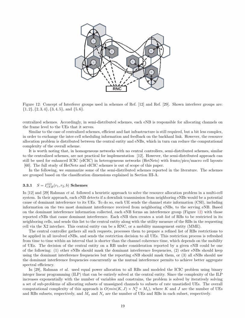
Figure 12: Concept of Interferer groups used in schemes of Ref. [12] and Ref. [29]. Shown interferer groups are:{1, 2}, {2, 3, 4}, {3, 4, 5}, and {5, 6}.
centralized schemes. Accordingly, in semi-distributed schemes, each eNB is responsible for allocating channels onthe frame level to the UEs that it serves.
Similar to the case of centralized schemes, efficient and fast infrastructure is still required, but a bit less complex,in order to exchange the inter-cell scheduling information and feedback on the backhaul link. However, the resourceallocation problem is distributed between the central entity and eNBs, which in turn can reduce the computationalcomplexity of the overall scheme.
It is worth noting that, in homogeneous networks with no central controllers, semi-distributed schemes, similarto the centralized schemes, are not practical for implementation [12]. However, the semi-distributed approach canstill be used for enhanced ICIC (eICIC) in heterogeneous networks (HetNets) with femto/pico/macro cell layouts[60]. The full study of HetNets and eICIC schemes is out of scope of this paper.
In the following, we summarize some of the semi-distributed schemes reported in the literature. The schemesare grouped based on the classification dimensions explained in Section III-A.
3.3.1 S = ISDeNB(r1, r2, b) Schemes
In [12] and [29] Rahman et al. followed a heuristic approach to solve the resource allocation problem in a multi-cellsystem. In their approach, each eNB detects if a downlink transmission from neighboring eNBs would be a potentialcause of dominant interference to its UEs. To do so, each UE sends the channel state information (CSI), includinginformation on the two most dominant interference received from neighboring eNBs, to the serving eNB. Basedon the dominant interference information collected, each eNB forms an interference group (Figure 12) with thosereported eNBs that cause dominant interference. Each eNB then creates a wish list of RBs to be restricted in itsneighboring cells, and sends this list to the central entity along with the utility measure of the RBs in the requestingcell via the X2 interface. This central entity can be a RNC, or a mobility management entity (MME).
The central controller gathers all such requests, processes them to prepare a refined list of RBs restrictions tobe applied in all involved eNBs, and sends the restriction decision to all UEs. This restriction process is refreshedfrom time to time within an interval that is shorter than the channel coherence time, which depends on the mobilityof UEs. The decision of the central entity on a RB under consideration reported by a given eNB could be oneof the following: (1) other eNBs should mask the dominant interference frequencies, (2) other eNBs should keepusing the dominant interference frequencies but the reporting eNB should mask them, or (3) all eNBs should usethe dominant interference frequencies concurrently as the mutual interference permits to achieve better aggregatespectral efficiency.
In [29], Rahman et al. used equal power allocation to all RBs and modeled the ICIC problem using binaryinteger linear programming (ILP) that can be entirely solved at the central entity. Since the complexity of the ILPincreases exponentially with the number of variables and constrains, the problem is solved by iteratively solvinga set of sub-problems of allocating subsets of unassigned channels to subsets of rate unsatisfied UEs. The overallcomputational complexity of this approach is O(min(K,J) × N4
s ×Ms), where K and J are the number of UEsand RBs subsets, respectively, and Ms and Ns are the number of UEs and RBs in each subset, respectively.
19

On the other hand, in [12], Rahman et al. divided the computations to be shared between the central entityand the eNBs. The algorithm at the eNB uses the iterative Hungarian algorithm in order to process the RBrestriction requests of the UE, and generate the wish list of RB restrictions. The wish list is then forwardedto the central entity that solves the restriction requests in an optimal manner and returns the decision to theinvolved eNBs to apply it locally.Two RB restriction approaches were proposed in this scheme: (1) droppingthe RB, or (2) using the RB but with 10 dB lower power. The overall complexity of the cell-level algorithm isO(M × N + (min(M, N))2 × max(M, N)), which is dominated by the complexity of the Hungarian algorithm,where M and N are the number of UEs and RBs in a cell, respectively. Whereas the complexity of the algorithm atthe central controller is O(L×Nr), where L is the number of cells that have conflicting restriction requests and Nr
is the number of RBs under consideration for restriction. The results of the performance evaluation of this schemecan be summarized as follows:
• Higher throughput can be achieved by restricting more and more RBs which implies more penalties to neighboringcells. However, substantial gain can be achieved by restricting only the most dominant interferer, and thus, onlythis interferer should be restricted. Only in the case of severely rate deprived UEs, the two most dominantinterferers can be restricted.
• An average of 12.5% to 20% of RBs need to be restricted in each cell in order to obtain high throughput gains.However, this large number of RB restrictions in each cell causes a considerable loss in resource, and thus, onlyjustifiable restrictions should be made. To that end, the following two restriction policies were evaluated in [12]:(1) RB restrictions are made only in favor of UEs that have received less than the average service in the cell,and (2) RB restrictions are also made for the UEs with good service status only when a considerable gain canbe achieved. The two policies represent a trade-off between performance and signaling overhead complexity asthe latter provides better performance at the cost of an increased number of restricted RBs and higher signalingoverhead. This is due to the fact that in the second policy all UEs need to forward information of the two mostdominant interferers to the serving eNB and not only the rate deprived UEs as in the first policy.
• Restricting RBs by totally dropping the RBs achieves performance for edge-UE that is comparable to the reuse-3scheme, while at the same time maintains a lower cell throughput and delay performance as compared to thereuse 1 scheme. On the other hand, restricting RBs by only lowering the used power by 10 dB maintains the cellthroughput and delay performance at levels similar to that of the reuse 1 scheme, but at the cost of a reducedbenefit to edge-UEs.
Although, a central entity is required for the resolution of the conflicting requests, the algorithm can be appliedto homogenous networks without a central controller (eg., 3GPP LTE and LTE-Advanced networks) with expecteddegradation in performance as conflict resolution is expected to be suboptimal. In this case, resolutions can beperformed through negotiations among neighboring eNBs using X2 interface that inter-connects eNBs. If two eNBswish to restrict a RB to each other, the decision should result in favor of the eNB that foresees higher utilizationon that RB. Accordingly, the proposed scheme can be classified as a coordinated-distributed scheme.
3.3.2 S = TSDRNC(0, 0, b) Schemes
In [30], Li et al. presented a semi-distributed scheme that reduces the overhead and computational load requiredto exchange all channel state information (CSI) of UEs and traffic status information between the eNBs and thecentral entity at the frame level. The scheme proposes splitting the resource allocation decision between the centralentity and eNBs. At super-frame level, the central entity makes decision on which RB is used by which eNB andrecommends a UE to be assigned to the RB to maximize the system throughput and minimize ICI. Then, at theframe-level, eNBs make the actual pairing between the RB and the UE. For a given particular frame, if the UErecommended by the central entity has traffic to send, the eNB will agree with the recommendation of the centralentity; Otherwise, if this UE has no traffic to send in any of the frames of the super-frame, the eNB will makeits own decision based on the traffic (buffer occupancies) of the UE and fading channel conditions. As a result,the RB is always assigned to the UE with the highest utility value, which is a function of both channel and trafficconditions. Given that at each super-frame, the interference from neighboring eNBs to UEs is pre-determined bythe RBs to eNBs allocation made by the central entity, thus, re-allocating a RB to a UE with traffic to send insteadof the recommended UE with no traffic, will always result in an improved throughput for the eNB.
According to the above discussion, it appears that the decision algorithm of the central entity performs inter-ference avoidance, whereas the decision algorithm of the eNB performs channel/traffic adaptation. Specifically,the central entity will be dedicated to coordinate the mutual interference between cells, which will reduce the in-formation update rate between the central entity and the eNBs to a super-frame level. The eNBs, on the other
20

Figure 13: Graph coloring of the outer optimization problem used in scheme of Ref. [31].
hand, will make real time decisions on RB assignment at the user packet level (frame level). As a result, both themutual interference diversity and the fading channel/bursty traffic diversity are efficiently exploited. However, oneof the main disadvantages of this scheme is the allocation of an equal power to all RBs to simplify the central entityalgorithm. Manipulating the RB allocated power can achieve higher spectral efficiency by allocating the same RB indifferent cells at different power levels, and lower ICI by minimizing the power levels of the dominating interferers.
The central entity algorithm uses a greedy approach to assign a RB to the UE that has the highest systemthroughput improvement value within a certain eNB. The RBs to eNBs assignment is progressively performedto provide the most improvement to the system throughput. If none of the UEs in an eNB has a positive systemthroughput improvement value, then the RB is not assigned to this particular eNB. Throughput ratios (proportionalto the number of active users) are set among the cells to prevent edge-UE starvation. Also, the RB assignmentalways starts with the eNB that is most under-assigned and ends with the eNB that is most over-assigned as theorder with which eNBs are evaluated has a considerable impact on the overall final throughput. The first eNB willenjoy the use of a “clear” channel, whereas, the rest of eNBs will suffer from the interference resulted from previousassignments. When no more eNBs can increase the overall throughput of the network by using a particular RB,the RB is not assigned to any additional eNBs. Finally, the eNB algorithm attempts to find the UE that has thehighest throughput for each RB.
The algorithms discussed above perform the needed operations for both interference avoidance and traffic adap-tation with a linear-complexity with respect to the number of users and channels. The computational complexitiesof the central entity and the eNB algorithm are, respectively, O(N × L ×MeNB) and O(NeNB ×MeNB). WhereN is the number of RBs, L is the number of eNBs, MeNB is the number of users in an eNB, and NeNB is thenumber of RBs assigned by the RNC to an eNB. It is worth pointing that, since the computational complexity ofthe central entity algorithm is a function of the number of the eNBs, this algorithm may not operate efficiently forsystems that has small cells with a large number of interfering eNBs.
In [31], Neckera et al. split the RB allocation problem into an outer and inner optimization problems as follows.
• The outer optimization problem is solved at the central entity and is modeled as a global interference graph basedon the global UEs information collected from all eNBs. In this graph, the vertices represent the UEs, and theedges represent critical interference relations between them. The goal is to find a set of colors (set of RBs) forevery UE such that there is no conflict between any combinations of colors in the sets. This problem is knownas fractional graph coloring and can be briefly explained as follows. First, the graph is constructed by evaluatingthe interference that a transmission to one UE causes to any other UE. For each UE, the total interference thatthe UE receives from other eNBs is calculated. The largest interferers are then blocked from using the same setof RBs by establishing a relation in the interference graph. Resources need to be assigned to UEs such that notwo UEs are assigned the same resources if they are connected in the graph.
To solve the outer optimization problem, first the graph is colored by means of the sub-optimal heuristic Dsatur(sequential graph coloring algorithm heuristic). Next, all UE are traversed in a random order and assigned asecond color where possible. The process is then repeated until no more extra colors can be assigned to anyUE as illustrated in Figure 13. Color assignment is based on that the largest interferers are blocked from using
21

the same RBs. RBs need to be assigned to the UEs such that no two UE are assigned the same RB if they areconnected in the graph. The computational complexity of the outer optimization algorithm is O(M2 + M ×N),where M is the number of UEs in all cells and N is the number of RBs.
• The inner optimization problem is solved locally at each eNB and is modeled as a local interference graph based onthe local state information and subject to the allocation constraints delivered by the outer optimization problem,which is solved at the central coordinator and results are communicated to the eNB at regular time intervals (inthe order of seconds). The goal of the inner optimization problem is to coordinate the transmissions in a cell byassigning every UE to one or more RB. However, those RBs must be chosen from the set of RBs assigned to thisUE by the central entity.
The inner optimization problem is then solved by means of genetic algorithms. Initially, all UE are listed alongwith their RBs that were assigned during the outer optimization. A placement algorithm traverses the list andassigns the first possible and free RB to the UEs. The RBs must not yet be occupied, and the assignment must notbe in conflict with the inner interference graph. During the subsequent iterations, possible solutions (assignmentmatrices) are evaluated with the objective of maximizing the number of scheduled UEs.
The effect of the number of possible solutions in the pool (P ) and the number of iterations/generations (G) onthe edge-UE performance was studied in [31]. It was found that at small G, edge-UEs will most likely be notserved, thus decreasing the edge-UEs performance. The aggregate throughput however, depends much less onthe G than the edge-UE throughput. The same also holds for the number of possible solutions in the pool P .It was observed that as few as G= 10 generations bring the number of unserved UEs below one. For G= 100,the algorithm comes close to its optimum performance. The best performance for a small computational effortcan be achieved for P ≈ 2 ×G. The inner optimization algorithm (based on genetic algorithms) computationalcomplexity is O(P ×G).
From the above, it appears that the complexity of the inner optimization algorithm is low as the genetic algorithmconverges after few number of generations. This allows for efficient hardware-based real-time implementations ofthe algorithm. However, the computational complexity of the outer optimization algorithm is function of the squareof the number of all UEs in the system, which makes it difficult for this algorithm to converge in timely manner fornetworks with large number of UEs.
Similar to work reported in [30], Neckera et al. in [31] allocate equal power to all RBs to simplify the centralentity algorithm which minimizes the resources utilization. However, manipulating the RB allocated power canachieve higher spectral efficiency by allocating the same RB in different cells at different power levels, and lowerthe ICI by minimizing the power levels of the dominating interferers.
3.4 Coordinated-Distributed Schemes
Frequent RB allocation updates may lead to a higher throughput as they allow for capturing more accurate inter-ference avoidance gain and partial fading diversity gain information [30]. As a result, a better decision-makingprocess can be performed especially in the emerging systems that support high user mobility. Centralized andSemi-distributed schemes are often too heavy to be implemented as all the interference information on all RBs haveto be gathered at a central controller. In reality, the amount of information needed from eNBs to the central entitycan be prohibitively large [30]. Consequently, the frequency of exchanging information with the central entity mustbe reduced, which in turn may degrade the overall performance of the system. A scheme needs to make a trade-offbetween increasing coordination between eNBs, to increase the overall system throughput; and reducing the cost ofbackhaul communication and intra-node processing [49].
In coordinated distributed schemes, resource allocation is performed only at the eNB level, without the needof a central entity to perform the coordination. However, coordination is still needed between eNBs to exchangeCSI reports in order to perform global ICIC. Such coordination must be taken into consideration when designingcoordinated distributed schemes, especially in very fast fading environments due to the fact that the LTE X2 interfaceused for coordination has a non-negligible latency [45].
Coordinated distributed schemes have a clear advantage over the semi-distributed schemes presented above. Suchadvantages include reducing time and signaling overhead resulted from regular communication between eNBs andthe central entity, and reducing the network infrastructure complexity by eliminating the central entity. Thus,coordinated distributed schemes are more attractive for practical implementation. However, the realization of theseschemes has remained limited largely due to constraints on inter-eNB communication and the latencies involved ininformation exchange for distributed eNBs [53].
22

Several Coordinated distributed schemes have been proposed in the literature (e.g., [32]- [40]). Schemes underthis category typically partition the complex multi-cell optimization problem into distributed single-cell optimizationproblems. These single-cell optimization problems can be solved by each individual eNB using local informationfrom the served UEs while exchanging minimal amount of information required for global ICIC with neighboringeNBs. It worth noting that, some of the schemes under this category make an implicit use of some of the conceptsin the frequency reuse schemes discussed in Section II. For example, the schemes proposed in [32]- [35] adopt thepower constraints of the soft frequency reuse (SFR) scheme.
In the following, we summarize some of the coordinated-distributed schemes reported in the literature. Theschemes are grouped based on the classification dimensions introduced in Section III-A.
3.4.1 S = ICDUE (r1, r2, f) Schemes
In [32], Triki et al. proposed the Exchange-based Interference Coordination (EIC) algorithm based on resourceexchange and borrowing between eNBs. The proposed algorithm runs on the eNBs with no need for a centralcoordinator. It depends entirely on the local information from the served UEs and the information exchangedbetween neighboring eNBs. The EIC algorithm is performed in the following three phases:
• Initial phase: in this phase the available bandwidth is divided into three non-overlapping sub-bands and eachsub-band is assigned to an eNB making a cluster of three eNBs. In other words, the scheme starts with a reuse-3configuration. The authors define the owner eNB of a RB as the eNB that has this RB in the sub-band that wasinitially assigned to this eNB.
• Proactive phase: in this phase, eNBs starts borrowing RBs from their neighboring eNBs if the owned RBs cannotsatisfy the minimum rates of their UEs. The authors define the borrowing eNB of a RB as the eNB that borrowsthis RB from a neighboring eNB (i.e, the requested RB is not in the sub-band initially assigned to the borrowingeNB). The following activities occur during the borrowing process:
i Each eNB evaluates the quality of its RBs and sends a Load Information Message (LIM) to its neighbors. TheLIM contains the status of each and every RB of the eNB, including whether the RB is allocated or not andthe level of interference in this RB (high, medium, low, or clear). The level of interference value is determinedusing a set of predefined thresholds. One of the weak points of this algorithm is that no method or study isprovided to optimize the values of these thresholds and understand their effect on the overall performance.
ii A borrowing eNB, which desires to borrow a RB outside its sub-band, chooses the best RB among thoseavailable in the LIM. The utilization of this RB by the borrowing eNB must not cause harmful interferenceto the owner eNB of this RB. This check can be performed since each eNB knows the assigned sub-bandfor every neighboring eNB. To prevent harmful interference to the owner eNB due to RB borrowing, theborrowing eNB compares the interference level of all “borrower-able” RBs on the owner eNB to a pre-definedborrowing threshold. If RB interference level is inferior to the borrowing threshold, the eNB can borrow theRB without further information of the RB owner eNB. While taking the borrowing decision based on a staticthreshold is simple, the authors state that the choice of other borrowing decision mechanisms may improve theperformance of the proposed algorithm, without necessary changing the operational concept of the algorithm.
• Reactive phase: in this phase the owner eNBs exchange the interference level of the borrowed RBs belongingoriginally to their sub-band. According to interference level of the RB, borrowing eNBs adapt their transmissionpower used for the borrowed RB. The borrowing eNB reduces the transmission power of a borrowed RB by 25%if it receives high interference indicator for this RB from the owner eNB for the first time. If the borrowing eNBreceives a second high interference indicator, it reduces again the transmission power by another 25%. If the levelof interference remains high and the borrowing eNB receives a third high interference indicator, the borrowingeNB releases immediately the RB to avoid causing higher interference to the owner eNB.
The proposed EIC algorithm runs periodically, where each period is triggered by a proactive phase (RBs borrowing)followed by three successive reactive phases (borrowed RBs power adjustments). At the beginning of a proactivephase, the eNB releases the borrowed RBs that suffer from a high interference and keeps the other borrowed RBsand their transmission power if they are still needed.
The performance evaluation of the EIC algorithm showed that it outperforms static SFR in terms of throughputand number of served users, while utilization a lower number of resources. This high spectral efficiency ( bits
RB ) ofthe EIC algorithm is attributed to the efficient selection of RBs during the proactive phase and the efficient powermanagement of RBs at the reactive phase.
23
The computational complexity of the proactive phase (RBs borrowing) is O(M×L×N), where M is the numberof unsatisfied UE in a cell, L is the number of neighboring eNBs, and N is the number of RBs available for borrowingfrom a neighboring eNB. The computational complexity of the reactive phase (borrowed RBs power adjustments) isO(N). As the available bandwidth is divided into three non-overlapping sub-bands and each sub-band is assignedto an eNB, the number of RBs available for borrow from a neighboring eNB N represents the whole neighboringsub-band, which is third of the available bandwidth.
Zheng et al. in [38] proposed a novel distributed QoS-guaranteed ICIC scheme. This scheme is based onallowing edge UEs in an over-loaded cell to send to the neighboring eNBs a request of restraining them from usingthe same RBs. Thus, under-loaded cells make concessions to the requesters and shoulder part of the heavy burdenof the over-loaded cell in a new form of load balancing. The proposed scheme contains the following two procedures,both of which are performed by the eNB on two different time levels:
• The intra-cell fast scheduling algorithm based on the Hungarian algorithm is performed on the frame level to assignRBs to UEs to meet their QoS targets. The algorithm decisions are based on the instantaneous (frame level CQIreports) SINR of UEs considering the instantaneous channel gain which is related to flat fading and fast fading.During this process, certain under-served UEs have the opportunity to prepare a request of limiting the use ofsome of their currently scheduled RBs in their dominant interfering cells. The authors define an under-servedUE as a UE with the ratio of its target data rate to its average data rate greater than unity. The complexity ofthis intra-cell fast scheduling algorithm is O((M ×N)2), where M and N are the numbers of the UEs and RBsin the cell, respectively. Although the intra-cell scheduling takes into account the UEs’ fairness, it cannot resolvethe problem of severe throughput degradation of edge UEs when the cell is over- loaded as this problem requiresactions form other eNBs. Thus, this inter-cell interference coordination algorithm is used to achieve global ICIC.
• The inter-cell interference coordination (ICIC) algorithm based on X2 interface is performed on the super-framelevel to require other eNBs to reduce the transmitting power on certain dominant interference RBs, or to requestnot to use them at all based on the UE’s restriction lists. The coordination among eNBs needs backhaul commu-nication and signaling overhead. However, only medium-to-long term interactions between eNBs through the X2interface are required. The eNBs employ the ICIC algorithm on a super-frame level to limit the usage of someRBs in order to minimize interference for over-loaded cells. The algorithm decisions are based on the long term(super-frame level CQI reports) SINR considering long term channel gain, which is related to large scale pathloss and shadow fading. This algorithm consists of the following three operations:
i Over-loaded eNBs check eligibility of the restriction request : Restricting RBs causes degradation in the spectralefficiency, hence the authors proposed the Integral based Eligible UE Selection (I-EUS) algorithm to choosewhich UE’s restriction requests to be sent to the dominant interferers. The I-EUS algorithm considers a therestriction request if an UE eligible if the averaged ratio over the super-frame of the UE’s target data rateto its average data rate exceeds a pre-defined threshold. The method of choosing the value for this thresholdand the effect of this value on the algorithm performance were not discussed in [38]. A key characteristic ofthe I-EUS algorithm is that it takes into account the depth of hunger of under-served UEs in terms of QoS(under-served in a severe degree for a short period of time) as well as in the time domain (under-served ina lesser degree but for a long period of time). Requests under both cases will be accepted as the decision isbased on the averaged ratio over the super-frame. Furthermore, from the perspective of load balancing, theissuing of eligible requests can be regarded as an indicator that the cell is over-loaded. The complexity of theI-EUS algorithm is O(L×M), where L is the number of the eNBs, and M is the number of the UEs in thecell.
ii Over-loaded eNBs prepare and send eligible restriction requests to the dominant interferers: For eligible UEs,the eNB begins sending restriction requests to the dominant interferers starting by the worst RB to the lessworst RB, until the UE’s target data rate is met. According to the eligible UE’s channel condition on each ofthose RBs, the UE can either require the dominant interferer to reduce the transmitting power on the RB orforce it not to use the RB. To make the decision, the authors proposed to compare the achievable rate of theUE, in case the dominant interferer reduced the transmitting power on the RB, to a pre-defined threshold.If the achievable rate of the UE was larger than the threshold, then only power reduction request is sent;Otherwise, a restriction request is sent. However, the selection of the value of the threshold and its impact onthe performance of the algorithm were not studied in [38]. The complexity of this step is O(L×Me ×Nu),where L is the number of the eNBs, Me is the number of the eligible UEs in the cell, and Nu is the numberof RBs scheduled for the UE.
24

iii Under-loaded eNBs resolve the received requests: Since each over-loaded eNB compiles the list of restrictionrequest independently, problem remains at the under-loaded eNBs (eNBs that receives restriction requests) tomake a decision on which RBs to restrict, which to reduce their power, and which to leave as is. For instance,an under-loaded eNB might receive, for the same RB, two restriction requests from two of its neighbors andthree power reduction requests from three other neighbors. For each RB, the proposed ICIC scheme groupseNBs requests of similar restriction type (e.g., total restriction or power reduction) and calculates the expectedrate gains if this restriction type is applied on the RB. Accordingly, the restriction type that maximizes therate gain is selected. The computational complexity of this process is O(L × N), where L is the number ofeNBs, and N is the number of RBs.
Once the ICIC algorithm determines the permitted RBs for each cell, certain RBs may be unavailable to UEs, orcertain RBs become particularly good to select. Then, the UE level resource allocation is performed by the fastscheduling algorithm in the next super-frame.
To reduce the computational and signaling complexity of the scheme above, authors suggested to limit the coor-dination to be within 7 cells only, making the algorithm suboptimal, yet practical. Even with this limitation, thecomputational complexity of this scheme is still relatively high compared to other coordinated-distributed schemes.This scheme follows the same strategy of restricting RBs presented in [12], but without the use of a central entity,which makes the scheme more practical for homogenous networks, and reduces the overall infrastructure complex-ity, and hence cost. It is worth pointing that this scheme, unlike the scheme proposed in [12], exploits full powercontrol, which leads to a higher spectral efficiency.
3.4.2 S = PCDeNB(r1, 0, f) + TCD
eNB(0, r2, f) Schemes
In [33], Quek et al. combined the conventional SFR scheme [9] [Figure 6-(a)] with an adaptive frequency and powerresource allocation approach. In this scheme, the SFR scheme is first used to assign channels to eNBs, and each eNBthen uses heuristics and suboptimal algorithms to allocate power and RBs to active UEs to guarantee a minimumachievable rate to all edge UEs. Unlike the previous schemes that divide the problem based on the timing level(super-frame and frame), this scheme divides the power and RB allocation problem to two sub-problems for edgeand center UEs, respectively. Both problems are solved on the frame level using the instantaneous received SINR. Ageometry-based approach was adopted for user group partitioning, where the edge and center UEs are differentiatedbased on their distances from the serving eNB. The following is a brief description of the two algorithms used foredge and center UEs.
• Sum Power Minimization algorithm for edge UEs: The first sub-problem is to allocate RBs to all edge UE toachieve a pre-defined minimum rate. Edge UEs have low SINR due to presence of ICI and significant path-loss.Thus, the most efficient way to improve their rate is to allocate more power to increase the SINR instead ofincreasing the bandwidth. This is the main idea of the Sum Power Minimization Algorithm for edge UEs. Afterthe fixed sub-channel allocation using SFR, the algorithm starts with a single RB as the minimum number of RBsto be allocated to an edge UE and assumes fixed and equal power on all sub-channels. The algorithm iterativelysolves the sum power minimization problem to allocate power to the different sub-channels allocated to edge UEswithout exceeding the total transmission power of the eNB and subjected to a minimum rate constraint whereeach edge UE must achieve a pre-defined minimum rate. The algorithm ends by defining the set of edge sub-channels. The rest of the sub-channels are available for center UEs. Each eNB then shares the local sub-channeland power allocation with other eNBs. eNBs use the information exchanged between them to adapt the SFRplanning to the traffic conditions. The computational complexity of this algorithm is O(Me ×Ne
4), where Me isthe number of edge UE, and Ne is the number of edge sub-channels.
• Weighted Sum Rate Maximization algorithm for center UE: The second sub-problem is to use the remaining sub-channels to maximize the throughput of the cell-center UEs. Center UEs generally have high SINR since they arecloser to the serving eNB and faraway from the interfering eNBs. Thus, the most effective way to improve therate of these UEs is to allocate more bandwidth instead of power. The proposed algorithm implements this ideaby first uniformly allocating the residual transmit power over the remaining sub-channels, and then allocatingthe remaining sub-channels to the center UEs with the aim of maximizing the sum rate. The computationalcomplexity of this algorithm is O((Mc ×Nc)2), where Mc is the number of center UEs, and Nc is the number ofcenter sub-channels.
While edge UEs suffers the most, and thus, they were the main (and in most cases, the only) focus of most dynamicschemes, maximizing the rate of center UEs leads to a higher system utilization, and thus, it is important to optimize
25
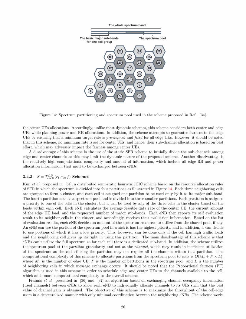
The whole spectrum band
The spectrum pool The basic major sub-bands for one cell-group
1 9
21
20
10
12
11
1
3
2
22
24
23
13
15
14
4
6
5
25
27
26
16
18
17
7
9
8
Figure 14: Spectrum partitioning and spectrum pool used in the scheme proposed in Ref. [34].
the center UEs allocations. Accordingly, unlike most dynamic schemes, this scheme considers both center and edgeUEs while planning power and RB allocations. In addition, the scheme attempts to guarantee fairness to the edgeUEs by ensuring that a minimum target rate is pre-defined and fixed for all edge UEs. However, it should be notedthat in this scheme, no minimum rate is set for center UEs, and hence, their sub-channel allocation is based on besteffort, which may adversely impact the fairness among center UEs.
A disadvantage of this scheme is the use of the static SFR scheme to initially divide the sub-channels amongedge and center channels as this may limit the dynamic nature of the proposed scheme. Another disadvantage isthe relatively high computational complexity and amount of information, which include all edge RB and powerallocation information, that need to be exchanged between eNBs.
3.4.3 S = TCDeNB(r1, r2, f) Schemes
Kun et al. proposed in [34], a distributed semi-static heuristic ICIC scheme based on the resource allocation rulesof SFR in which the spectrum is divided into four partitions as illustrated in Figure 14. Each three neighboring cellsare grouped to form a cluster, and each cell is assigned one partition to be used only by it as its major sub-band.The fourth partition acts as a spectrum pool and is divided into three smaller partitions. Each partition is assigneda priority to one of the cells in the cluster, but it can be used by any of the three cells in the cluster based on theloads within each cell. Each eNB calculates the average feasible data rate of the center UE, the current amountof the edge UE load, and the requested number of major sub-bands. Each eNB then reports its self evaluationresult to its neighbor cells in the cluster, and accordingly, receives their evaluation information. Based on the listof evaluation results, each eNB decides on amount of the spectrum resources to utilize from the shared pool, if any.An eNB can use the portion of the spectrum pool in which it has the highest priority, and in addition, it can decideto use portions of which it has a low priority. This, however, can be done only if the cell has high traffic loadsand the neighboring cell gives up its right in using this partition. The main disadvantage of this scheme is thateNBs can’t utilize the full spectrum as for each cell there is a dedicated sub-band. In addition, the scheme utilizesthe spectrum pool at the partition granularity and not at the channel, which may result in inefficient utilizationof the spectrum as the cell utilizing the partition may not require all the channels within that partition. Thecomputational complexity of this scheme to allocate partitions from the spectrum pool to cells is O(Me + P × L),where Me is the number of edge UE, P is the number of partitions in the spectrum pool, and L is the numberof neighboring cells in which message exchange occurs. It should be noted that the Proportional fairness (PF)algorithm is used in this scheme in order to schedule edge and center UEs to the channels available to the cell,which adds more computational complexity to the overall scheme.
Fraimis et al. presented in [36] and [37] an algorithm based on exchanging channel occupancy information(used channels) between eNBs to allow each eNB to individually allocate channels to its UEs such that the bestvalue of channel gain is obtained. The objective of this scheme is to maximize the throughput of the cell-edgeusers in a decentralized manner with only minimal coordination between the neighboring eNBs. The scheme works
26

1
3
2 1
3
2 1
3
2
1
3
2 1
3
2
1
3
2
Cell
Pseudo - cell
BS 3
BS 1 BS 2 1
3 2
Figure 15: Structure of the pseudo-cell concept used in the scheme proposed in [35].
as follows. The algorithm first attempts to find, using the exchanged information, a channel that is not used byan UE in any of the adjacent cells to allocate to edge UEs. The eNB tries to find the least used channels by theneighbors and assign them to the edge UEs. The process continues until all edge UEs are assigned channels orthere are no more available channels. Next, the scheme starts allocating equal power to all edge UEs. One of thelimitations of this scheme is that it assumes that an UE can be allocated a single channel only. This is assumptionis not practical as it limits the achievable rate of an UE to the maximum achievable rate of best channel it canget. Another limitation in this scheme is the equal power allocation to all edge-users. This is not practical as edgeusers may be allocated channels that are used by neighboring cells, while others may be allocated interference-freechannels. Accordingly, the former users may require higher power than the latter. The computation complexity ofthis scheme is O(ME ×N), where ME is the number of edge UEs, and N is the number of channels.
3.4.4 S = TCDeNB(r1, r2, b) Schemes
In [35], Kwon et al. proposed a scheme that attempts to minimize the maximum value of the QoS violationratios in each sector. QoS violation ratio is defined as the ratio of the number of users whose rate requirementsare not satisfied to the total number of users. Assuming that the SINR value is identical for all the sub-carriersbelonging to one sub-carrier group (SG) or channel, users feed back the channel condition on SG level to decreasethe amount of feedback information. The system attempts to compute the value of the frequency reuse factor(FRF) of SGs dynamically and distribute the sub-carriers with high FRFs differentially among the neighboringsectors according to their load conditions. In this scheme, resource allocation is managed independently at each“pseudo-cell” composed of the major-interfering sectors belonging to the neighboring cells (See Figure 15) in orderto reduce the signaling and computation overhead. For each SG, two values of FRF can be applied, either reuse-1or reuse-Ns, where Ns denotes the number of sectors within one pseudo-cell. When FRF is 1, each sector within thepseudo-cell can utilize all the corresponding sub-carriers in the SG for data transmission. On the other hand, whenFRF is Ns, the sub-carriers are divided into Ns sectors, that is, each sector can utilize only the sub-carriers thatbelong to itself. A two-step approach is implemented, that first distributes the subcarrier groups to the constituentsectors and then arranges each sector to allocate its resource to the users independently as follows:
• First step: the inter-sector resource allocation algorithm is used to determine the amount of SGs with FRF =1 and that with FRF = Ns, and then divide the sub-carriers in SGs with FRF = Ns into the Ns sectors. Theinter-sector resource allocation algorithm is adapted to the load condition determined by the number of usersin the sector, their geographic distribution, and their requirements. The algorithm works by determining thepreferred FRF value of each user. This value is determined by comparing a predetermined threshold to the valuesof the ratio between the average data rate of a user on all SGs over one super-frame when FRF value is Ns and1. If the value of the ratio is larger than the threshold, then this means that the interference avoidance gain islarge, and accordingly, Ns is taken as the preferred FRF value of this user. Otherwise, the preferred value is setto 1. The computational complexity of this algorithm is O(M × (N + 1)), where M is the number of UEs in thesector, and N is the number of SGs.
• Second step: the intra-sector resource allocation algorithm is used to allocate the sub-carriers of each sector tothe users, which is done independently in each sector. The best possible SG for each user is determined based onthe effective data rate achieved by this assignment. To do so, the algorithm first selects the user with the largest
27

ratio of the remaining data rate, i.e., the difference between the requirement and the currently allocated data rate,to the required data rate and then allocate to the selected user a sub-carrier in its best subcarrier group. Thisprocess is repeated until no available sub-carrier remains or all user requirements are satisfied. In the case wheretwo or more users do not obtain their required data rate even after completing the above resource allocationprocess; a reallocation process is performed. In the reallocation process, sub-carriers from the most satisfiedusers are recalled and then reallocated to those users who did not get the desired data rate. This reallocationprocess is repeated until the QoS violation ratio cannot be further reduced. The computational complexity ofthis algorithm is O(M ×max(M,N) ×N × S), where M is the number of UEs in the sector, N is the numberof SGs, and S is the number of sub-carriers. While this scheme guarantees the required QoS, its computationalcomplexity is relatively high as it depends on the number of sub-carriers and users.
3.4.5 S = TCDeNB(0, 0, f) Schemes
In [39], Son et al. presented a strategy similar to that proposed in [38] (discussed in Section III.D) but with areduced complexity. In this scheme, all eNBs can use all the channels for data transmission (reuse-1); however, theoriginal optimization problem that requires intractable computation complexity for global optimality is decomposedinto per-eNB sub-problems. At each slot, each eNB needs to determine: (1) which UE is scheduled on each channel,and (2) how much power is allocated for each scheduled UE on each channel. For the eNB to make its decision,only reference users’ feedback information is considered instead of considering all other cell’s UEs suffering from theeNB interference. A reference user refers to the worst UE in another cell receiving the largest interference from theeNB. For an eNB to carry a per-slot resource allocation, a number of parameters for each of the candidate referenceusers need to be collected by neighboring eNBs and forwarded in advance to that eNB through signaling. Theparameters for a reference user are: its weight presented as the inverse of its average throughput, its received signalstrength, and its noise plus interference strength. To reduce the per-slot message exchanged between neighboringeNBs, each eNB calculates the average of the needed parameters for all candidate reference users and sends them,infrequently, to its neighboring eNBs. Each eNB maintains a table containing these average values of candidatereference users. Thus, the only thing that needs to be exchanged at each slot is the indices of scheduled users.Once each eNB receives the indices of scheduled users from neighboring eNBs, it uses the parameters in the tablecorresponding to the received indices. The computational complexity of this scheme is O(N×M) for UE schedulingand O(N) power allocation, where N is the number of channels and M is the number of UEs. Compared to othercoordinated schemes, this scheme shows a relatively low computational complexity. In addition, the use of referenceusers significantly reduces the the signaling complexity of the scheme.
3.4.6 S = TCDeNB(0, 0, b) Schemes
In [40], Kimura et al. proposed a distributed coordination scheme for the LTE downlink systems to optimize thefractional frequency reuse (FFR) of the different bands based on the variations in the cell loading. This is donein a distributed manner, with communication between eNBs through the X2 interface. This idea can be viewedas an implementation approach for the concept of dynamic FFR discussed in [41]. In dynamic FFR, cell-centrezone boundaries (across the network) are dynamically adapted (shrink/expand) depending on user behavior, cellload, and interference situation from other neighboring cells. Thus the proposed scheme works on selecting cell-edgebands optimized according to the time-variant environment using the interference level reports, and/or signalingvia interface between eNBs. As shown in Figure 16, cell centre areas have different sizes. For instance, in the figure,Cell 1 is highly loaded while cell 3 experiences a lower load. Accordingly, the region of frequency reuse 1 appearslarger in cell 1 compared to cell 3. According to the results reported in [40], this scheme outperforms “reuse-1”and slightly outperforms the static FFR in terms of 5% CDF throughput averaged over the whole time period;while having the same average cell throughput as in the carefully planned static FFR. The scheme adopts staticpower allocation approach, and thus, all edge-RBs are allocated equal power that is higher than that allocatedto center-RBs. This approach reduces the overall computations required to allocate power levels, but as pointedbefore, it leads to inefficient power distribution.
A limitation in this scheme is that each eNB can only select a pre-determined number of RBs as edge-bands,which limits the capability of the scheme in dealing with irregular cell shapes where large number of edge usersmay exist. This limitation causes the proposed scheme to suffer from the so-called fake unavailability of edge-RBs,which may limit the number of served users as in the case of PFR and SFR. Clearly, a crucial design factor in thisscheme is the selection of the pre-determined number of edge-RBs. The computation complexity of this scheme isO(N ×L + NE), where N is the number of all RBs, L is the number of neighbouring eNBs, and NE is the numberof edge RBs. It is worth pointing that the generalized proportional fairness (GPF) scheduling algorithm [51] is
28
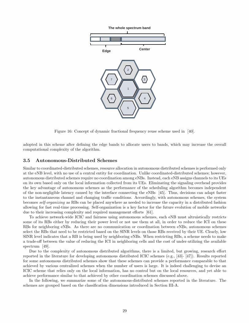
7
2
1
6
3
5
4
The whole spectrum band
Edge Center
Figure 16: Concept of dynamic fractional frequency reuse scheme used in [40].
adopted in this scheme after defining the edge bands to allocate users to bands, which may increase the overallcomputational complexity of the algorithm.
3.5 Autonomous-Distributed Schemes
Similar to coordinated-distributed schemes, resource allocation in autonomous distributed schemes is performed onlyat the eNB level, with no use of a central entity for coordination. Unlike coordinated-distributed schemes; however,autonomous distributed schemes require no coordination among eNBs. Instead, each eNB assigns channels to its UEson its own based only on the local information collected from its UEs. Eliminating the signaling overhead providesthe key advantage of autonomous schemes as the performance of the scheduling algorithm becomes independentof the non-negligible latency caused by the interface connecting the eNBs [45]. Thus, decisions can adapt fasterto the instantaneous channel and changing traffic conditions. Accordingly, with autonomous schemes, the systembecomes self-organizing as RBs can be placed anywhere as needed to increase the capacity in a distributed fashionallowing for fast real-time processing. Self-organization is a key factor for the future evolution of mobile networksdue to their increasing complexity and required management efforts [61].
To achieve network-wide ICIC and fairness using autonomous schemes, each eNB must altruistically restrictssome of its RBs either by reducing their power level or not use them at all, in order to reduce the ICI on theseRBs for neighboring eNBs. As there are no communication or coordination between eNBs, autonomous schemesselect the RBs that need to be restricted based on the SINR levels on those RBs received by their UE. Clearly, lowSINR level indicates that a RB is being used by neighboring eNBs. When restricting RBs, a scheme needs to makea trade-off between the value of reducing the ICI in neighboring cells and the cost of under-utilizing the availablespectrum [49].
Due to the complexity of autonomous distributed algorithms, there is a limited, but growing, research effortreported in the literature for developing autonomous distributed ICIC schemes (e.g., [43]- [47]). Results reportedfor some autonomous distributed schemes show that these schemes can provide a performance comparable to thatachieved by various centralized schemes when the number of users is large. It is indeed challenging to devise anICIC scheme that relies only on the local information, has no control but on the local resources, and yet able toachieve performance similar to that achieved by other coordination schemes discussed above.
In the following, we summarize some of the autonomous-distributed schemes reported in the literature. Theschemes are grouped based on the classification dimensions introduced in Section III-A.
29

3.5.1 S = PADeNB(0, 0, f) Schemes
Stolyar et al. proposed a number of schemes in [43] and [44] based on the idea of dynamically allocating power tothe different sub-bands to create dynamic soft fractional frequency reuse (SFFR) patterns that can change accordingto the changes in the workloads and the location of UEs.
In [43], Stolyar et al., presented a self-organizing dynamic SFFR scheme for constant bit-rate (CBR) traffic,which requires no signaling or communication between eNBs. The presented scheme systematically and dynamicallyachieves a frequency reuse efficient for a given user spatial distribution. The scheme divides the bandwidth intoa number of sub-bands, each consists of a number of sub-carriers. Each eNB constantly performs a “selfish” opti-mization of the assignment of its power and UEs to sub-bands with the objective of optimizing its own performanceby minimizing its power usage. This optimization is done based on the other-cell interference levels reported byUEs for different sub-bands. To understand the idea of self-organizing dynamic SFFR scheme, it is important toobserve that, in a given cell: (1) edge UEs generally have larger power requirements, and more importantly, powerrequirements will be relatively smaller in some “good” sub-bands, where neighboring cells happen to allocate lesspower, and (2) center UEs generally have smaller power requirements; and they are less affected by the interferencefrom neighboring cells. Accordingly, an eNB that wants to minimize its power usage, it will have a tendency toput its edge UEs into its good sub-bands. Therefore, the cell will allocate larger powers to its good sub-bands;making them become “bad” for the neighboring cells. Neighboring cells then (while trying to minimize their owntotal powers, as well) will normally “avoid” assigning their edge UEs into those sub-bands, making them even “bet-ter” for the cell under consideration, and so on. The system “settles” into a user-to-sub-band allocation pattern,generally requiring less power in all cells, because neighboring cells will automatically “separate” their edge usersinto different sub-bands. While the scheme results in all sub-bands being utilized in all cells, a self-organizing reusepattern is created through non-uniform transmission of power across the different sub-bands, as most of the poweris transmitted on a subset of the sub-bands, while a small portion of the power is transmitted on the remainingsub-bands. A shadow scheduling algorithm that represents a special case of the Greedy Primal-Dual (GPD) algo-rithm is used for UEs scheduling, whereas a “fluid” model is used for power allocation of all users in all sub-bandsin a cell based on the SINR target and the transmit power that needs to be assigned. A disadvantage of the shadowalgorithm is that it solves the problem assuming the sub-carriers and power required by an UE are constant inorder to be able to iteratively update the optimal solution instead of keep solving the linear problem from scratch.However; in practice the sub-carriers and power required by an UE may change over time, especially with highlymobile UEs. The computation complexity of this scheme is O(2×M ×N), where M is the number of UEs, and Nis the number of sub-bands.
In [44], Stolyar et al., presented a power allocation algorithm for automatically adjusting the transmit powersin each sub-band, creating an efficient and dynamic soft fractional frequency reuse (SFFR) patterns for enhancingthe performance of OFDMA downlink under best-effort traffic. Each eNB runs the algorithm independently andrequires no exchange of information with other eNBs. The algorithm runs a fixed number of virtual time slotswithin each physical time slot to assign virtual power allocations to sub-bands until reaching the best allocation.The greater the number of virtual time slots is, the greater the accuracy of the algorithm and its responsivenessto changes in system state, but at an increase computational cost. The algorithm works on assigning power to thedifferent defined sub-bands to achieve a soft frequency reuse of the bands dynamically based on the location of theexisting workloads. After power allocation, a generalized proportional fair scheduling algorithm [51] is used forusers scheduling. Even though no apriori frequency planning is used, the algorithm; however, improves the cell edgedata throughputs, while maintaining the overall cell throughput at the same level as that achieved by the staticapproach. The scheme is shown to efficiently achieve a frequency reuse adapted to the UE loads and distribution.The computation complexity of this scheme is O(N×V ), where N is the number of sub-bands, and V is the numberof virtual time slots within each physical time slot. It is worth pointing that, this scheme does not consider userscheduling, so adding a user scheduling algorithm will increase the overall computational complexity of the scheme.
A main disadvantage of two schemes proposed by Stolyar et al. in [43] and [44] is that, in order to reduce thecomputation cost, the schemes operate at the granularity of the sub-bands not the RBs. Power allocation at thesub-band granularity level may lead to over allocating power to some of the RBs if they are located in a sub-bandthat serves edge UEs.
3.5.2 S = PADUE (r1, r2, f) Schemes
In [45], a distributed resource allocation algorithm is proposed by Cicalo et al. to preserve intra-cell fairness andcoordinate offline with neighboring cells for load balancing to support inter-cell fairness. The scheme provides aninter-cell interference partial coordination and uses the FFR static scheme for power planning to reduce compu-
30
tational complexity. The authors show that, distributed schemes with aggressive reuse manage to approach thecapacity of a centralized system when the number of users is large. One of the disadvantages of this scheme isthat it is not fully dynamic as it still requires some static configuration in the FFR power planning that cannot bechanged with the change of workloads, and thus, it makes the scheme unsuitable for use in systems with irregularcell configuration. Moreover, in this scheme, the fairness of rate allocation is confined within each cell. To provideglobal fairness for all users in all cells, an off-line algorithm is used to balances the eNBs load, making the schemenot capable to cope with fast changing workloads and high user mobility. The computation complexity of thisscheme is O(M2 × S), where M is the number of UEs, and S is the number of subcarriers in the cell. Accordingly,the scheme is dependent on the square of the number of users as well as the number of sub-carriers in the cell.This may limit the applicability of this scheme in LTE-Adv system with 1200 subcarrier at 20MHz [50] and a largenumber of highly mobile UEs.
3.5.3 S = PADUE (r1, r2, f) Schemes
In [46], Ko et al. introduced a power allocation algorithm called distributed inter-cell power allocation (DIPA)that improves the throughput-fairness trade-off by managing the power allocation to users suffering from highinterference without inter-eNB coordination. DIPA is designed to determine the power allocation preferred byeach UE individually by using a simplified version of the iterative water-filling scheme, and then incorporate theindividual power allocations into one policy. For the iterative water-filling process to converge within the coherencetime of the channel, the process is performed over a large time scale (super-frames of 1 sec) based on long-termaverage channel condition, not adapting to short-term instantaneous channel condition. Each UE measures theaverage inter-cell interference level on each channel over the previous super-frame period and compares it to theinterference threshold broadcasted by the eNB. An UE that suffers from high interference elects a number of channelswhere the average interference levels are the lowest, and sends the preference information to the eNB to which itassociates. Based on this feedback information, each eNB performs the power allocation procedure that incorporatesthe preferences of all the users. The power allocation procedure consists of two steps; the first step focuses on thehigh-interference users (HIU), whereas the second step focuses on the low-interference users. The DIPA algorithmdoes not consider a specific policy for user scheduling, though proportional fair scheduling algorithm [51] was usedin the algorithm evaluation. In contrast to power allocation, user scheduling is performed over a short time scale(frame level of 10 ms) based on the instantaneous channel conditions. This paper; however, did not provide a studyto guide the selection of the a proper value of the interference threshold. This value is crucial for operation of thealgorithm as it has a clear impact on the balancing the tradeoff between throughput and fairness; as the interferencethreshold increases so does the fairness at the expensive of a reduced throughput. The computation complexity ofthis algorithm is O((NHIU ×MHIU )2 + (N −NHIU )× (M −MHIU )), where NHIU is the set of channels preferredby the largest number of users within the high-interference users (HIU) group, MHIU is the number of users in theHIU group, N is the set of all channels in the cell, and M is the set of all users in the cell. The DIPA algorithmdoes not consider a specific policy for user scheduling, so the DIPA algorithm can be combined with any kind ofopportunistic scheduling algorithms, which clearly will add to the computational complexity of the algorithm.
3.5.4 S = IADUE (0, 0, f) Schemes
Duy La et al. proposed in [47] to use the game theory to solve the resources allocation problem in an autonomousdistributed fashion. In this study, UEs (players) compete for a given number of subcarriers by iteratively playing thebest-response game till convergence to Nash equilibrium. Each UE works on minimizing the utility function whichis defined as the total interferences generated by this UE to the environment plus the total interferences it receivesfrom the environment. The weakness of the formulation presented in [47] is that some strategies may dominateothers. For instance, UEs tend to use only single subcarrier to minimize interference leading to inefficient spatialreuse of frequencies. To prevent this dominating strategy, authors forced each UE to be allocated a predeterminedfixed number of sub-carriers limiting the OFDMA advantage of allowing UEs to intelligently select favorable sub-carriers for their transmission. Having a fixed number of sub-carriers predetermined for each UE constrains the UEsto a maximum achievable rate. The authors did not provide an algorithm for finding the optimal fixed number ofsub-carriers to be allocated to each UE. The computation complexity of this scheme is O(I ×M ×S!/Si!(S−Si)!),where I is the expected number of rounds of play until convergence, M is the number of UEs, S is the number ofsub-carriers in the system, and Si is the number of sub-carriers to be allocated to the ith user. This makes the schemedependent on the number of users as well as the number of sub-carriers in the system. When the total numberof sub-carriers is considerably large as the case in LTE-Adv (1200 subcarrier at 20MHz [50]), the convergencerate becomes impractical. Accordingly, the work proposed in [47] assumed unrealistic LTE-Adv environment of
31

5 subcarriers for fast convergence given that the minimum supported number of sub-carriers in LTE-Adv is 72subcarrier at 1.4 Mhz [50]. Finally, the study only focused on the assignment of sub-carriers and left the optimalallocation of power for a further study.
3.6 Design Trade-offs in Cell Coordination-Based ICIC Schemes
In this subsection, the impact of the different design aspects that affect the performance of the dynamic ICICschemes is discussed based on the observations obtained from the schemes reviewed above.
• Coordination: To perform network-wide ICIC in a multi-cell environment, decisions should be taken in a central-ized way at some central coordinator that is able to collect information from all users, and decide accordingly[52]. For a centralized controller to operate, large amount of UEs information need to be exchanged on the
backhaul link [30]. Centralized scheduling in multi-cell environment is a difficult task without the use of an effi-cient and fast infrastructure, due to the stringent time required to exchange the scheduling information and thelarge feedback required by the UEs [52]. Thus, in practice, the rate of exchanging information with the centralcoordinators should be kept at low frequencies, which in return may degrade the system’s performance. Also, asthe number of cells grows, so does the signaling complexity. For these reasons, emerging cellular networks, such asLTE-Advanced systems, rely mainly on inter-eNB coordination over the X2 interface with no central coordinatorin a flat architecture [50]. Based on the above discussion, it can be seen that a fully distributed approach withno central controller seems to be more practical in order to facilitate the decision-making process with a small orno signaling delays, which can cope with the instantaneous network conditions. Moreover, eliminating the centralcontroller also reduces the overall infrastructure complexity, and hence, cost. After all, a decision must be madeto balance the trade-off between the high eNBs coordination that may increase the overall system throughput,and the high cost of signaling that allows for exchanging sufficient information for coordination [49].
• Computational complexity : The problem of resource allocation with dynamic demand is known to be NP-hard[31]. Using an exact method is computationally infeasible as the problem involves extremely large search spaces
with correspondingly large number of potential solutions. As the new resource configurations must be computedat run-time, computational efficiency might be of a higher priority compared to model accuracy. One way toreduce the computational complexity of the various schemes in OFDMA systems, is to perform scheduling at ahigher granularity levels. In particular, scheduling at the RBs (e.g., [36]) which are in order of tens [50], ratherthan scheduling at the sub-carrier (e.g., [47]) which are in order of hundreds [50]. The granularity level shouldbe selected carefully to consider the natural reverse relation between granularity and control. For instance, oncecan schedule sub-bands to user groups as in [43]. This may reduce the overall complexity even more than in thecase of RBs as the number of sub-bands normally is less than ten; however, obviously, this reduction in complexitycomes with the cost of limited control in managing the available resources.
• Signaling complexity : For all cell-coordination based ICIC schemes, except the autonomous schemes, cooperationbetween eNBs is required in order to achieve network-wide ICIC in the multi-cell environment. To achieve suchcooperation, information need to be exchanged between the eNBs. In practical systems, the LTE X2 interfacehas a considerable latency [45], resulting in an additional delay on the exchanged information, that shouldbe taken into account, especially in very fast fading environments. Thus, ICIC schemes should minimize theamount of information need to be exchanges in order to comply with the stringent time required to exchange thescheduling information. Schemes that are based on exchanging only the reference UE information (e.g., [39])instead of all UEs information may result in a considerable reduction in the signaling complexity of the scheme.Another approach to reduce signaling complexity is to exchange only the information of the UEs suffering frominterference as in scheme proposed in [38]. Similar to the coordination point above, schemes need to make atrade-off between high coordination between eNBs which may increase the overall system throughput, and theexpense of the signaling complexity needed to exchange the required information between eNBs [49].
• Scheduling rate: Higher scheduling rates (i.e., more frequent RB allocation updates) bring higher throughput asit allows capturing more accurately the instantaneous channel gain, flat fading, and fast fading [30]. This inturn enables better decisions, especially in the emerging systems that support high user mobility. However, therate of UE reassignment to different RBs should be kept to minimum to reduce the incurred additional signalingoverhead [44]. In dynamic schemes other than autonomous schemes, scheduling is highly dependent on theinformation exchanged between the eNBs in order to achieve network-wide ICIC in the multi-cell environment.Thus, the scheduling rate is highly dependent on the latency and reliability of the interfaces connecting the eNBsalong with the amount of information need to be exchanged between them.
32

• Fairness: To guarantee fairness to edge UEs, a minimum target rate can be pre-defined and fixed for all edgeUEs as in the scheme proposed in [33]. This minimum rate constraint forces the rate of each edge UE to be atleast as large as this minimum rate. Similar minimum rate can be set for center UEs to guarantee fairness amongcenter UEs as well. A scheme needs to make a trade-off between achieving higher overall throughput and beingfair in allocating resources to all UEs [49].
• Optimization of edge-UEs power allocation: In traditional frequency reuse schemes, different disjoint sub-channelsubsets are assigned to different cells, with sub-channel subsets reused at spatially separated locations. Thisconcept exploits the fact that since the signal power falls off with distance, the same frequency spectrum can bereused at spatially-separated locations. As edge UEs suffer from low SINR on all RBs due to the presence of ICICand significant path-loss; thus, the most efficient way to increase their rate is to allocate more power to theseUEs instead of more bandwidth [33]. However, as the RBs used by edge UEs might be also used in neighboringcells, cooperation between all cells is required to reduce the ICI resulting for using high power for the edge UEs.In general, manipulating the RB allocated power can achieve higher spectral efficiency. This is done as the sameRB is used in different cells, but at different power levels. With power control, ICI can be reduced by reducingthe power levels of the dominating interferers.
• Optimization of center-UEs RB allocation: While edge UEs suffer the most, and thus, they were typically themain or even only focus of most proposed dynamic schemes, maximizing the rate of center UEs leads to a highersystem utilization. Center UEs generally have high SINR on most RBs since they are closer to the serving eNBand far from the interfering eNBs. Thus, the most effective way to improve the rate of these UEs is to allocatemore bandwidth instead of power [33].
• Initialization with pre-partitioned resources between cells and/or user groups: Using a static frequency allocationscheme to pre-plan the frequency and/or power allocation among cells and/or among user groups can helpin reducing the computational complexity of the scheduler as demonstrated in some schemes proposed in theliterature (e.g., [33], [40], [44]). However, this planned allocation limits the dynamicity of the scheme. Forexample, pre-planning the cells bands would limit the scheduler to schedule UE only to RBs in the cell’s allocatedband, preventing the scheduler from exploring other bands even if this would lead to a better performance and/orimproved resources utilization. In case of pre-planned resources partitioning among user groups, the schedulerwill not be able to use unused resources reserved for one user group to serve unsatisfied UEs in some other usergroup that has used its entire pre-allocated band.
4 Future Research Directions
In this section, we identify and discuss some challenges related to the design and analysis of ICIC scheme that makeinteresting future research directions.
• Evaluation Framework and Benchmark : Due to the complexity of the dynamic ICIC problem, most of theperformance evaluations are based on simulation models. A principal problem with simulation evaluations duringcomparing different schemes is the lack of common context, scenarios and evaluation metrics [48]. Accordingly,an evaluation framework and a benchmark are needed to allow researchers to develop and evaluate their ICICschemes in a sound manner. Such an effort will provide researchers with data sets for unified realistic scenarios(similar to those provided by the European Momentum project [59] for Berlin and Lisbon) that define commonrealistic conditions, such as: cells layout, number of channels, propagation data, and traffic intensity. Theevaluation framework should provide a unified set of metrics that can be used to evaluate and benchmark variousICIC schemes.
• Wireless Network Cloud (WNC): Recently, with the emergence of the cloud-computing technology and othertechnologies related to wireless infrastructure including software radio technology and remote radio head tech-nology, Wireless Network Cloud (WNC) with Base Station Pooling (BSP) is becoming an interesting alternativenetwork architecture where all eNBs computational resources (enabled by Software Radio) are pooled in a centrallocation and connected via fiber to simple radio-front ends (Remote Radio heads) mounted on remote cell-towers[54]. WNC provides all the necessary transmission and processing resources for a wireless access network to
operate in a central fashion [53]. A promising research direction is to re-think the way ICIC centralized schemesare structured by exploiting the transmission and processing resources of the WNC.
33
• Heuristics algorithms: An important line of work is to formulate the ICIC problem as an optimization taskwhose objective is to maximize the multi-cell throughput subject to: power constraints, inter-cell signalinglimitations, fairness objectives, and/or minimum bit rate requirements [49]. The problem of resource allocationwith dynamic demand is known to be NP-hard [31]. Using an exact method is computationally inefficient as theproblem involves extremely large search spaces with correspondingly large number of potential solutions. Whileoptimization models give an insight into the upper bounds of achievable ICIC gains, actually implementing thesenear optimal mechanisms can be economically and/or technologically infeasible. Thus, various lower complexityheuristics algorithms should be investigated as they have the power of obtaining good sub-optimal solutions in acomputationally efficient way.
• Autonomous schemes: Static schemes suffer from the limitation of being unable to adapt to inhomogeneoustraffic load and varying user group distribution within each cell [33]. Centralized and semi-distributed schemesare often too heavy for implementations in reality as all the interference information on all RBs has to be gatheredat a central controller, which is prohibitively large [30]. Coordinated-distributed schemes realization has remainedlimited largely due to constraints on inter-eNB communication and the latencies involved in information exchangefor distributed eNBs [53]. Self-organization is a key factor for the future evolution of mobile networks, due totheir increasing complexity and required management efforts [61]. Thus, with the current network architectureand large number of cells, it appears that the future is for autonomous schemes as they can achieve a good ICIClevel with no signaling overheads. Moreover, they open the way for a more flexible and adapted cell topologyas well as for new energy saving methods [61]. Not much research efforts have been reported in developingautonomous distributed ICIC schemes, which makes it an interesting research direction that is worth furtherinvestigation.
5 Summary
Inter-cell interference coordination (ICIC) schemes can be viewed as a scheduling strategy used to limit the inter-cell interference such that cell-edge users in different cells preferably are scheduled on complementary parts of thespectrum when needed. The common theme of ICIC avoidance schemes is to apply restrictions to the usage ofdownlink resources such time/frequency and/or transmit power resources. Such coordination of restrictions willprovide an opportunity to limit the interference generation in the area of the cellular network. Accordingly, Signalto Interference and Noise Ratio (SINR) can be improved at the receivers in the coverage area, which will providepotential for increased (cell-edge) data-rates over the coverage area, or increased coverage for given data-rates.
This paper presents a survey of various ICIC schemes used to alleviate the inter-cell interference problem inthe downlink of OFDMA-based cellular networks in order to improve cell-edge data rates and enhance the overallnetwork capacity. The paper reviews various ICIC schemes proposed under the two main interference avoidanceclasses, namely, the frequency reuse-based (static) and the cell coordination-based (dynamic). To this end, newclassification models are presented and used to describe the various schemes under the static and dynamic ICICavoidance classes.
Static ICIC schemes use methods to allocate subcarriers (frequency bands) among cells and sectors. Whereasdynamic schemes perform real-time cell coordination to allocate resources (frequency bands) to cells and sectors.Pre-allocated frequency reuse schemes are generally simple to implement; however, it is not easy to modify theirfrequency distributions among adjacent cells in response to the dynamics of the network. Cell coordination schemes,on the other hand, are more flexible as compared to frequency reuse schemes; however, they require complex signalingand coordination among cells.
Generally speaking, frequency reuse schemes are suitable for networks with a static even distribution of loads;however, they lead to significant performance degradation in terms of cell and user throughput when used due tothe natural dynamic nature of cellular systems, where there is an unevenly distributed dynamically changing load.Therefore, dynamic frequency allocations are needed in order to cope with the continuous load changes in cells. Incell coordination, interference reduction is realized by real time coordination among all involved cells to avoid thattwo cell edge UEs in neighboring cells use the same sub-carriers. Adaptive algorithms are developed in order toefficiently manage the resource utilization among cells without a priori resource partitioning. Coordination betweencells can be performed in either a centralized, semi- distributed or distributed fashion. Dynamic ICIC schemesreported in the literature are mostly either semi-distributed or distributed via coordination. A limited number ofautonomous distributed ICIC schemes have been proposed, and accordingly, more research efforts are needed inorder to develop autonomous schemes that can cope with the nature and needs of the emerging OFDMA-basedcellular networks with highly mobile users.
34
Acknowledgment
This work is part of the 4G++ project (4gpp-project.net) supported by the National Telecom Regulatory Authorityof Egypt (www.tra.gov.eg).
References
[1] E-UTRA and E-UTRAN Overall description: Stage 2 (Relase 8), 3GPP Technical Specification TS 36.300V8.70, Dec. 2008. Avaliable (July 2012): http://www.3gpp.org.
[2] Requirements for Further Advancements for E-UTRA (LTE-Advanced) (Relase 8), 3GPP Technical Specifica-tion TS 36.913 V8.0.0, Jun. 2008. Avaliable (July 2012): http://www.3gpp.org.
[3] 3GPP R1-050629, “Inter-cell interference mitigation,” Huawei, 2005. Available (July 2012): http://www.3gpp.org/ftp/tsg_ran/wg1_rl1/TSGR1_AH/LTE_AH_June-05/Docs/R1-050629.zip
[4] 3GPP R1-050764, “Inter-cell Interference Handling for E-UTRA,” Ericsson, 2005. Available (July 2012):http://www.3gpp.org/ftp/tsg_ran/WG1_RL1/TSGR1_42/Docs/R1-050764.zip
[5] 3GPP R1-050841, “Further Analysis of Soft Frequency Reuse Scheme,” Huawei, 2005. Available (July 2012):http://www.3gpp.org/ftp/tsg_ran/WG1_RL1/TSGR1_42/Docs/R1-050841.zip
[6] 3GPP R1-060291, “OFDMA Downlink inter-cell interference mitigation,” Nokia, 2006. Available (July 2012):http://www.3gpp.org/ftp/tsg_ran/WG1_RL1/TSGR1_44/Docs/R1-060291.zip
[7] 3GPP R1-060368, “Performance of Inter-Cell Interference Mitigation with Semi-Static Frequency Planning forEUTRA Downlink,“ Texas Instruments, 2006. Available (July 2012): http://www.3gpp.org/ftp/tsg_ran/WG1_RL1/TSGR1_44/Docs/R1-060368.zip
[8] R. Kwan and C. Leung, “A Survey of Scheduling and Interference Mitigation in LTE,” Electrical and ComputerEngineering, vol. 2010, 2010.
[9] 3GPP R1-050507, ”Soft Frequency Reuse Scheme for UTRAN LTE,” Huawei, 2005. Available (July 2012):http://www.3gpp.org/ftp/tsg_ran/WG1_RL1/TSGR1_41/Docs/R1-050507.zip
[10] N. Hassan and M. Assaad, “Optimal Fractional Frequency Reuse (FFR) and resource allocation in multiuserOFDMA system,” in Proc. Int. Conf. Information and Communication Technologies ICICT09., 2009, pp. 88-92.
[11] F. Khan, LTE for 4G Mobile Broadband: Air Interface Technologies and Performance.: Cambridge UniversityPress, 2009.
[12] M. Rahman and H. Yanikomeroglu, “Enhancing cell-edge performance: a downlink dynamic interference avoid-ance scheme with inter-cell coordination,” IEEE Transactions on Wireless Communications, vol. 9, no. 4, pp.1414-1425, 2010.
[13] M. Porjazoski and B. Popovski, “Analysis of Intercell interference coordination by Fractional frequency reusein LTE,” in Proc. Int Software, Telecommunications and Computer Networks (SoftCOM) Conf., 2010, pp.160-164.
[14] M. Porjazoski and B. Popovski, “Contribution to analysis of Intercell interference coordination in LTE: Afractional frequency reuse case,” in Proc. Global Mobile Congress (GMC)., 2010, pp. 1-4.
[15] L. Chen and D. Yuan, “Soft frequency reuse in large networks with irregular cell pattern: How much gainto expect?,” in Proc. IEEE 20th Int Personal, Indoor and Mobile Radio Communications Symp., 2009, pp.1467-1471.
[16] IEEE C802.16m-08/782, “Fractional Frequency Reuse in Uplink,” LG Electronics, 2008. Available (July 2012):www.ieee802.org/16/tgm/contrib/C80216m-08_782.doc
[17] Y. Kwon, O. Lee, J. Lee, and M. Chung, “Power Control for Soft Fractional Frequency Reuse in OFDMASystem,” in Computational Science and Its Applications ICCSA 2010, David Taniar et al., Eds.: SpringerBerlin / Heidelberg, 2010, vol. 6018, ch. 7, pp. 63-71.
35
[18] E. Yaacoub and Z. Dawy,“A Survey on Uplink ResourceAllocation in OFDMA Wireless Network,” IEEECOMMUNICATIONS SURVEYS & TUTORIALS, VOL. 14, NO. 2, SECOND QUARTER 2012, pp. 322-337,2012.
[19] D. Kim, J. Ahn, and H. Kim, “Downlink Transmit Power Allocation in Soft Fractional Frequency ReuseSystems,” ETRI Journal, vol. 33, pp. 1-5, 2011.
[20] R. Ghaffar and R. Knopp, “Fractional frequency reuse and interference suppression for OFDMA networks,”in Proc. 8th Int Modeling and Optimization in Mobile, Ad Hoc and Wireless Networks (WiOpt) Symp., 2010,pp. 273-277.
[21] F. B. Mugdim, “Interference Avoidance Concepts,” WINNER II project, 2007.
[22] E. Haro, S. Ruiz, D. Gonzalez, M. Garcia-Lozano, and J. Olmos, “Comparison of Different Distributed Schedul-ing Strategies for Static/Dynamic LTE Scenarios,” Technical University of Wien, 2009.
[23] K. T. Kim and S. K. Oh, “An Incremental Frequency Reuse Scheme for an OFDMA Cellular System and ItsPerformance,” in Proc. IEEE Vehicular Technology Conf. VTC Spring 2008., 2008, pp. 1504-1508.
[24] Z. Xie and B. Walke, “Resource allocation and reuse for inter-cell interference mitigation in OFDMA basedcommunication networks,” in Proc. 5th Annual ICST Wireless Internet Conf. (WICON)., 2010, pp. 1-6.
[25] C.-S. Chiu and C.-C. Huang, “Combined Partial Reuse and Soft Handover in OFDMA Downlink Transmission,”in Proc. IEEE Vehicular Technology Conf. VTC Spring 2008., 2008, pp. 1707-1711.
[26] A. Gjendemsjo, D. Gesbert, G. E. Oien, and S. G. Kiani, “Optimal Power Allocation and Scheduling for Two-Cell Capacity Maximization,” in Proc. 4th Int Modeling and Optimization in Mobile, Ad Hoc and WirelessNetworks Symp., 2006, pp. 1-6.
[27] Suman Das, Harish Viswanathan, and G. Rittenhouse, ”Dynamic load balancing through coordinated schedul-ing in packet data systems,” in Proc. IEEE INFOCOM 2003., 2003, vol. 1, pp. 786-796.
[28] Thomas Bonald, Sem Borst, and Alexandre Proutiere, ”Inter-Cell Scheduling in Wireless Data Networks,” inProc. 11th European Wireless Conference 2005., 2005, pp. 1-7.
[29] M. Rahman and H. Yanikomeroglu, ”Multicell Downlink OFDM Subchannel Allocations Using Dynamic Inter-cell Coordination,” in Proc. IEEE Global Telecommunications Conf. GLOBECOM ’07., 2007, pp. 5220-5225.
[30] G. Li and H. Liu, “Downlink Radio Resource Allocation for Multi-Cell OFDMA System,” IEEE Transactionson Wireless Communications, vol. 5, no. 12, pp. 3451-3459, 2006.
[31] M.C. Necker, “A Novel Algorithm for Distributed Dynamic Interference Coordination in Cellular Networks,”in Proc. KiVS, pp. 233-238, 2011.
[32] A. Triki and L. Nuaymi, “Intercell Interference Coordination Algorithms in OFDMA Wireless Systems,” inProc. IEEE 73rd Vehicular Technology Conf. (VTC Spring)., 2011, pp. 1-6.
[33] T. Q.S. Quek, Z. Lei, and S. Sun, “Adaptive interference coordination in multi-cell OFDMA systems,” in IEEE20th International Symposium on Personal, Indoor and Mobile Radio Communications, 2009, pp. 2380-2384.
[34] K. Dong, H. Tian, X. Li, and Q. Sun, “A Distributed Inter-Cell Interference Coordination Scheme in DownlinkMulticell OFDMA Systems,” in Proc. 7th IEEE Consumer Communications and Networking Conf. (CCNC).,2010, pp. 1-5.
[35] H. Kwon, W.-I. Lee, and B. Gi Lee, “Low-Overhead Resource Allocation with Load Balancing in Multi-cellOFDMA Systems,” in IEEE 61st Vehicular Technology Conference, 2005, pp. 3063-3067.
[36] I. G. Fraimis, V. D. Papoutsis, and S. A. Kotsopoulos, “A distributed radio resource allocation algorithm withinterference coordination for multi-cell OFDMA systems,” in Proc. IEEE 21st Int Personal Indoor and MobileRadio Communications (PIMRC) Symp., 2010, pp. 1354-1359.
[37] I. G. Fraimis, V. D. Papoutsis, and S. A. Kotsopoulos, “A Decentralized Subchannel Allocation Scheme withInter-Cell Interference Coordination (ICIC) for Multi-Cell OFDMA Systems,” in Proc. IEEE Global Telecom-munications Conf. GLOBECOM 2010., 2010, pp. 1-5.
36
[38] S. Zheng, H. Tian, Z. Hu, L. Chen, and J. Zhu, “QoS-Guaranteed Radio Resource Allocation with DistributedInter-Cell Interference Coordination for Multi-Cell OFDMA Systems,” in Proc. IEEE 71st Vehicular TechnologyConf. (VTC 2010-Spring)., 2010, pp. 1-5.
[39] K. Son, S. Lee, Y. Yi, and S. Chong, “Practical dynamic interference management in multi-carrier multi-cell wireless networks: A reference user based approach,” in 8th International Symposium on Modeling andOptimization in Mobile, Ad Hoc and Wireless Networks, 2010, pp. 186 - 195.
[40] D. Kimura, Y. Harada, and H. Seki, “De-Centralized Dynamic ICIC Using X2 Interfaces for Downlink LTESystems,” in Proc. IEEE 73rd Vehicular Technology Conf. (VTC Spring)., 2011, pp. 1-5.
[41] S.-E. Elayoubi, O. Ben Haddada, and B. Fourestie, “Performance evaluation of frequency planning schemes inOFDMA-based networks,” IEEE Transactions on Wireless Communications, vol. 7, no. 5, pp. 1623-1633, 2008.
[42] S. Sadr, A. Anpalagan and K. Raahemifar,“Radio Resource Allocation Algorithms for the Downlink of Mul-tiuser OFDM Communication Systems,” IEEE COMMUNICATIONS SURVEYS & TUTORIALS, vol. 11, no.3, THIRD QUARTER 2009, pp. 92-106, 2009.
[43] A. L. Stolyar and H. Viswanathan, “Self-Organizing Dynamic Fractional Frequency Reuse in OFDMA Sys-tems,” in Proc. INFOCOM 2008. The 27th Conf. Computer Communications. IEEE., 2008, pp. 691-699.
[44] A. L. Stolyar and H. Viswanathan, “Self-Organizing Dynamic Fractional Frequency Reuse for Best-EffortTraffic through Distributed Inter-Cell Coordination,” in Proc. IEEE INFOCOM 2009., 2009, pp. 1287-1295.
[45] S. Cicalo, V. Tralli, and A.I. Perez-Neira, “Centralized vs Distributed Resource Allocation in Multi-CellOFDMA Systems,” in IEEE 73rd Vehicular Technology Conference, 2011, pp. 1 - 6.
[46] S. Ko, H. Seo, H. Kwon, and B. G. Lee, “Distributed Power Allocation for Efficient Inter-cell InterferenceManagement in Multi-cell OFDMA Systems,” in 16th Asia-Pacific Conference on Communications, 2010, pp.243-248.
[47] Q. D. La, Y. H. Chew, and B.-H. Soong, “An Interference Minimization Game Theoretic Subcarrier AllocationAlgorithm for OFDMA-Based Distributed Systems,” in IEEE Global Telecommunications Conference, 2009,pp. 1-6.
[48] I. Katzela and M. Naghshineh, “Channel assignment schemes for cellular mobile telecommunication systems:a comprehensive survey,” IEEE Personal Communications, vol. 3, no. 3, pp. 10-31, 1996.
[49] G. Fodor, Ch. Koutsimanis, A. Rcz, N. Reider, A. Simonsson, and W. Mller, “Intercell Interference Coordina-tion in OFDMA Networks and in the 3GPP Long Term Evolution System,” Journal of Communications, vol.4, no. 7, pp. 445-453, 2009.
[50] S. Sesia, I. Toufik, and M. Baker, “LTE The UMTS Long Term Evolution: from theory to practice,” Wileypublishing, 2009.
[51] C. Wengerter, J. Ohlhorst and A. G. E. von Elbwart, “Fairness and throughput analysis for generalizedproportional fair frequency scheduling in OFDMA,” in Proc. IEEE 61st Vehicular Technology Conf. VTCSpring 2005., 2005, vol.3, pp.1903-1907.
[52] V. Corvino, D. Gesbert and R. Verdone, “A Novel Distributed Interference Mitigation Technique using PowerPlanning,” in Proc. IEEE Wireless Communications and Networking Conf. WCNC 2009, 2009, pp.1-6.
[53] P. Gupta, A. Vishwanath, S. Kalyanaraman and Y. H. Lin, “Unlocking Wireless Performance with Co-operationin Co-located Base Station Pools,” In Proc. Second International Conference on Communication Systems andNetworks (COMSNETS), 2010, pp. 1-8.
[54] Z. Zhu, Q. Wang, Y. Lin, P. Gupta, S. Sarangi, Sh. Kalyanaraman and H. Franke, “Virtual Base Station Pool:Towards A Wireless Network Cloud for Radio Access Networks,” In Proc. 8th ACM International Conferenceon Computing Frontiers (CF ’11), 2011, pp.34:1-34:10.
[55] D. Gonzalez, M. Garcia-Lozano, S. Ruiz and J. Olmos, “Static Inter-Cell Interference Coordination Techniquesfor LTE Networks: A Fair Performance Assessment,” In Proc. the Third international conference on Multipleaccess communications (MACOM’10), 2010, pp.211-222.
37

[56] D. Gonzalez, M. Garcia-Lozano, S. Ruiz and J. Olmos, “On the Performance of Static Inter-cell Interference Co-ordination in Realistic Cellular Layouts,” Mobile Networks and Management (MONAMI 2010), Lecture Notesof the Institute for Computer Sciences, Social Informatics and Telecommunications Engineering (LNICST),vol. 68, no. IV, pp.163-176, 2011.
[57] S. Zhang, “Inter-cell interference coordination in indoor LTE systems,” Masters Thesis, Royal Institute ofTechnology, Sweden, 2011.
[58] R. Verdone, H. Buehler, N. Cardona, A. Munna, R. Patelli, S. Ruiz, P. Grazioso, A. Zanella, A. Eisenblatterand H. Geerdes, “MORANS White Paper - Update,” Technical Report available as TD(04)062, COST 273,Athens, Greece, pp. 26-28, January 2008.
[59] European project IST-2000-28088, http://momentum.zib.de, 2005.
[60] M. Kamel and K. Elsayed, “Performance Evaluation of a Coordinated Time-Domain eICIC Framework based onABSF in Heterogeneous LTE-Advanced Networks,”. in Proc.IEEE Global Telecommunications Conf. (GLOBE-COM ’12), 2012, (To appear).
[61] U. Barth and E. Kuehn, “Self-organization in 4G mobile networks: Motivation and vision,” in Proc. 2010 7thInternational Symposium on Wireless Communication Systems (ISWCS), 2010, pp. 731 -735.
[62] 3GPP TS 36.213 V10.5.0, “E-UTRA Physical layer procedures,” 3rd Generation Partnership Project, 2012.Available (July 2012): http://www.3gpp.org/ftp/Specs/archive/36_series/36.213/36213-a50.zip
38

Table 1: Summary of Frequency Reuse-Based Schemes.Scheme Name(s) Representation with proposed notation
B = {B1}R = {r1}
Reuse-1 α = {a1}Figure 3-(a) s1 = s2 = s3 = {B1(a1, r1)}
B = {B1, B2, B3}R = {r1}
Reuse-3 α = {a1}(Hard frequency s1 = {B1(0, 0), B2(0, 0), B3(a1, r1)}
reuse [57]) s2 = {B1(0, 0), B2(a1, r1), B3(0, 0)}Figure 3-(b) s3 = {B1(a1, r1), B2(0, 0), B3(0, 0)}
B = {B1, B2, B3, B4}PFR [12] R = {r1, r2}
(FFR-FI [8] α = {a1, a2} )(Hard frequency s1 = {B1(a1, r1), B2(0, 0), B3(0, 0), B4(a2, r2)}
reuse [33]) s2 = {B1(a1, r1), B2(0, 0), B3(a2, r2), B4(0, 0)}Figure 4 s3 = {B1(a1, r1), B2(a2, r2), B3(0, 0), B4(0, 0)}PFR with B = {B1, B2, B3, B4}only one R = {r1, r2}
interference α = {a1, a2}in the worst s1 = {B1(a1, r1), B2(a2, r2), B3(0, 0), B4(a2, r2)}
case [22] s2 = {B1(a1, r1), B2(0, 0), B3(a2, r2), B4(a2, r2)}Figure 5 s3 = {B1(a1, r1), B2(a2, r2), B3(a2, r2), B4(0, 0)}
B = {B1, B2, B3}R = {r1, r2}
SFR α = {a1, a2}(Original) s1 = {B1(a1, r1), B2(a1, r1), B3(a1, r1) ∪ B3(a2, r2)}
[9] s2 = {B1(a1, r1), B2(a1, r1) ∪ B2(a2, r2), B3(a1, r1)}Figure 6-(a) s3 = {B1(a1, r1) ∪ B1(a2, r2), B2(a1, r1), B3(a1, r1)}
B = {B1, B2, B3}R = {r1}
SFR α = {a1, a2}(2nd definition) s1 = {B1(a1, r1), B2(a1, r1), B3(a2, r2)}
[11] s2 = {B1(a1, r1), B2(a2, r2), B3(a1, r1)}Figure 6-(b) s3 = {B1(a2, r2), B2(a1, r1), B3(a1, r1)}
B = {B1, B2, B3, B4}R = {r1, r2}α = {a1, a2}
s1 = {B1(a1, r1), B2(a1, r1), B3(a1, r1), B4(a2, r2)}SFFR [16] s2 = {B1(a1, r1), B2(a1, r1), B3(a2, r2), B4(a1, r1)}Figure 7 s3 = {B1(a1, r1), B2(a2, r2), B3(a1, r1), B4(a1, r1)}
B = {B1, B2, B3}FFR with R = {r1, r2, r3}multiple α = {a1, a2, a3}user class s1 = {B1(a3, r3), B2(a1, r1), B3(a2, r2)}
[21] s2 = {B1(a2, r2), B2(a3, r3), B3(a1, r1)}Figure 8 s3 = {B1(a1, r1), B2(a2, r2), B3(a3, r3)}
B = {B1, B2, B3}R = {r1}α = {a1}
s1 = {B1(a1, r1), B2(a1, r1), B3(a1, r1)}IFR [23] s2 = {B2(a1, r1), B3(a1, r1), B1(a1, r1)}Figure 9 s3 = {B3(a1, r1), B1(a1, r1), B2(a1, r1)}
B = {B1, B2, B3, B4, B5, B6}R = {r1, r2}α = {a1, a2}
s1 = {B1(a2, r2), B2(a1, r1), B3(0, 0),B4(a1, r1), B5(0, 0), B6(a1, r1)}
s2 = {B1(0, 0), B2(a1, r1), B3(a2, r2),B4(a1, r1), B5(0, 0), B6(a1, r1)}
EFFR [24] s3 = {B1(0, 0), B2(a1, r1), B3(0, 0),Figure 10 B4(a1, r1), B5(a2, r2), B6(a1, r1)}
39
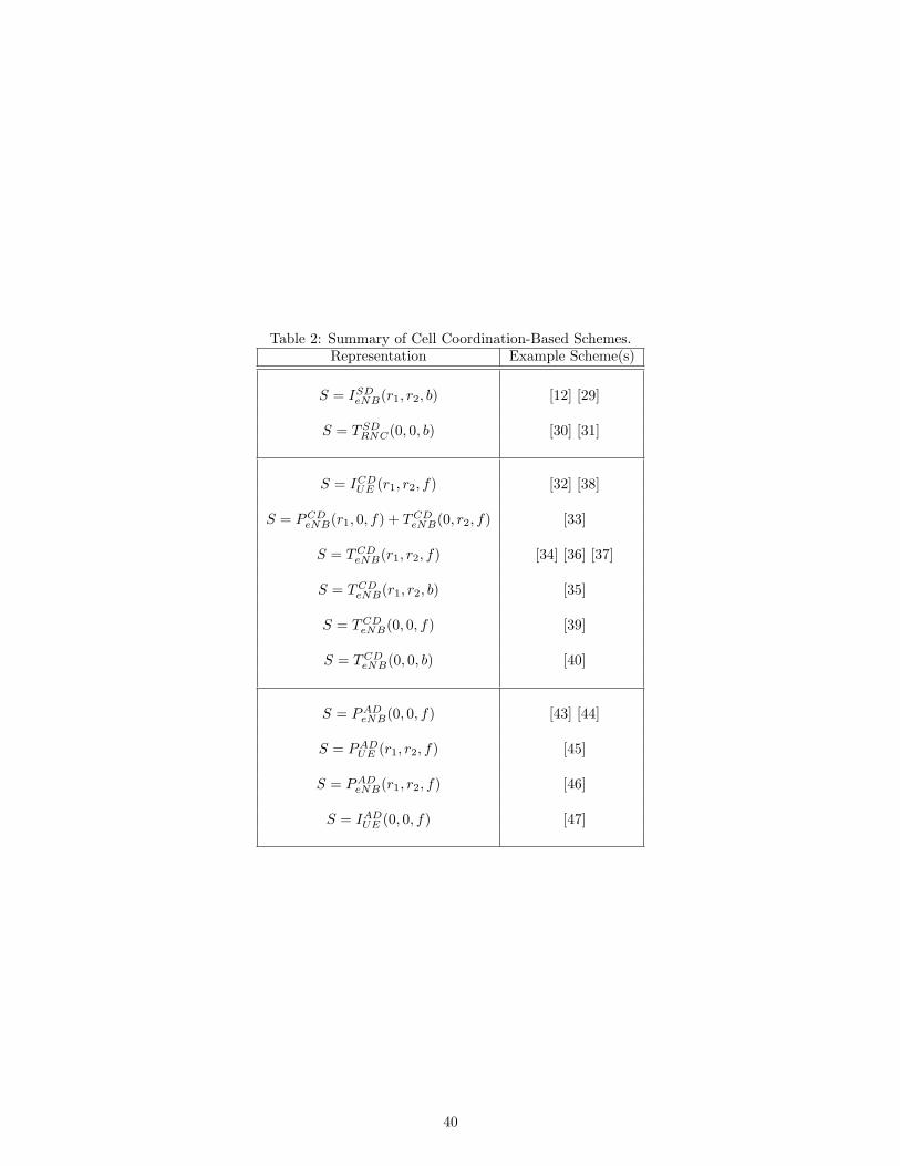
Table 2: Summary of Cell Coordination-Based Schemes.Representation Example Scheme(s)
S = ISDeNB(r1, r2, b) [12] [29]
S = TSDRNC(0, 0, b) [30] [31]
S = ICDUE (r1, r2, f) [32] [38]
S = PCDeNB(r1, 0, f) + TCD
eNB(0, r2, f) [33]
S = TCDeNB(r1, r2, f) [34] [36] [37]
S = TCDeNB(r1, r2, b) [35]
S = TCDeNB(0, 0, f) [39]
S = TCDeNB(0, 0, b) [40]
S = PADeNB(0, 0, f) [43] [44]
S = PADUE (r1, r2, f) [45]
S = PADeNB(r1, r2, f) [46]
S = IADUE (0, 0, f) [47]
40