a systems engineering methodology for analyzing systems of …faculty.nps.edu/thuynh/conference...
TRANSCRIPT

1
A Systems Engineering Methodology for
Analyzing Systems of Systems Using the Systems
Modeling Language (SysML)∗
Thomas V. Huynh1 and John S. Osmundson2
1Department of Systems Engineering, 2Departments of Information Sciences and Systems Engineering,
Naval Postgraduate School,
University Circle, Monterey, CA 93943-5000
{thuynh,josmundson}@nps.edu
ABSTRACT
A systems engineering methodology for analyzing a system of systems (SoS) elucidated in this paper involves the use of process modeling, modeling of the SoS with the systems modeling language (SysML), and subsequent conversion of the resulting SysML model into an end-to-end system of systems executable object-oriented simulation model. A process is a series of actions undertaken by a system or a system of systems to produce one or more end results, typically products and services. The SysML extends and customizes UML 2 to support systems engineering activities in engineering of complex systems. The methodology represents part of our on-going research at the Naval Postgraduate School (NPS) in establishing an integrated methodology for SoS architecting and engineering to be used in industry. In this paper we will explain the methodology and emphasize the correspondence between the SysML representation of a conceptual SoS and its executable model (via Extend™); we will also illustrate the methodology with an exploratory application to analysis of a coalition U.S.-Singapore SoS architecture employed to counter terrorism emanating from the maritime domain. Our future work is aimed at extending the methodology and improving its rigor and tying it to ontological engineering.
Keywords: Maritime domain protection (MDP); architecture; system of systems
(SoS); SysML; SysML modeling of SoS; executable model
∗ This work was supported in part by a contract with the OUSD (AT&L) through System of Systems Engineering Center of Excellence (SoSECE).

2
1. INTRODUCTION
A system of systems (SoS) systems engineering problem involves analysis of existing
and proposed systems of systems architectures and analysis of architectures of complex
systems-of-systems [Osmundson and Huynh, 2005]. Processes are a series of actions
undertaken to produce products, services, or other end results used by systems. A
process modeling methodology for performing engineering analyses of systems of
systems has been developed at the Naval Postgraduate School (NPS) [Osmundson et al,
2004] over the past several years and has been successfully applied to a number of
example military systems of systems [Huynh and Osmundson, 2005]. The methodology
involves process modeling and the use of the unified modeling language (UML) to
represent SoS models [Osmundson, 2004; Osmundson and Huynh, 2005]. The main
difference between the work reported in this paper and the work described in
[Osmundson and Huynh, 2005] is the use of the systems modeling language (SysML) for
system modeling. [Hause et al, 2001] discusses the required extensions to UML in order
to model non-software systems. [Rao et al, 2006], also devoted to SysML modeling of
systems, observes that systems engineers are handicapped by the limitations of UML in
modeling non-software systems and that SysML has advantages over UML in systems
modeling.
A general-purpose modeling language for systems engineering, SysML is effective in
specifying requirements, system structure, functional behavior, and allocations during
specification and design phases of systems engineering.1 As shown by the SysML
diagram taxonomy and the Venn diagram, which depict the relationship between UML
1 In this paper, we use freely the material in [SysML Partners, 2005].

3
and SysML (Figure 1), SysML consists of re-used UML 2 diagrams and extensions of
some UML 2 diagrams. The major changes include enhancements to the composite
structure and activity diagrams and two new diagrams − the requirement and parametric
diagrams. Extensions mechanisms include stereotypes, metaclasses, and model libraries.
The SysML stereotypes define new modeling constructs by customizing the existing
UML 2 constructs with new properties and constraints. SysML diagram extensions
define new diagram notations that supplement diagram notations reused from UML 2. A
metaclass is a class whose instances are classes. Metaclasses are typically used to
construct metamodels. A metamodel is a model that defines the language for expressing
a model. A stereotype is a class that defines how an existing metaclass (or stereotype)
may be extended, and enables the use of platform or domain specific terminology or
notation in addition to the ones used for the extended metaclass.
Figure 1. Relationship between UML 2 and SysML [SysML Partners, 2005].
4
In a nutshell, the methodology elucidated herein involves the use of process
modeling, the SysML tool, and the subsequent conversion of the SysML view of an SoS
into an end-to-end SoS executable object-oriented simulation model. Also, the
methodology represents part of our on-going research in establishing an integrated
methodology for SoS architecting and engineering to be used in capstone projects and to
be extended for use in industry. The work described here applies to both problems of
forming a system of systems from stand-alone systems and problems of engineering a
system comprised of to-be-defined and to-be-developed systems.
The use of process modeling is elaborated in [Osmundson and Huynh, 2005]. The
scope of this paper emphasizes only the use of the SysML tool in representing an SoS in
general and a maritime domain protection (MDP) SoS in particular and its utility in
modeling and simulation of the SoS. Our goals in this paper are:
• Explain the SoS system engineering methodology using SysML and the mapping
of the SySML representation of an SoS to its computer model (via Extend™) and
emphasize the utility of the SysML model in building an executable model.
• Illustrate our approach with the analysis of a coalition SoS architecture employed
to counter terrorism emanating from the maritime domain.
The rest of the paper is organized as follows. In Section 2 we explain the SoS system
engineering methodology. In Section 3, we describe and apply the methodology to a
coalition MDP SoS. We illustrate it with a SysML model of the SoS, then subsequent
map the SysML model to an end-to-end SoS executable object-oriented simulation
5
model, using Extend™.2 Finally, Section 4 contains some concluding remarks and future
work.
2. SoS SYSTEMS ENGINEERING METHODOLOGY
Except for the use of SysML to model systems, our SoS systems engineering and
analysis methodology described here is similar to that in [Osmundson and Huynh, 2005].
It involves analyses, transformations, model building, and simulations. It consists of the
following steps: (1) Develop requirement diagrams; (2) Development of system of
systems scenarios and operational architectures; (3) Identification of system of systems
threads; (4) Representation of SoS operational architectures in using SysML; (5)
Identification of SoS design parameters and factor levels; (6) Transformation of the
SysML model into an executable model; (7) Application of design of experiments; and
(8) Simulation runs and analysis of results. Figure 2 depicts a condensed version of an
integrated process to capture these steps.
The SoS problem description statement leads to the definition of the use cases to be
incorporated in the use case diagrams, which aid in the development of scenarios. The
SysML requirements diagrams are developed using inputs from operational context
diagrams, which correspond to the Department of Defense Architecture Framework
(DoDAF) OV-1, operational requirements, SoS requirements, and the DoDAF SV-4,
which describes the functions the system of systems needs to perform. The DoDAF SV-
1 (Systems Interface) aids in the development of the SoS breakdown diagrams, which
employ block diagrams [Rao et al, 2006]. The DoDAF OV-5 (Operational Activity
Model) is mapped to the activity diagrams. The SoS threads, which corresponds to the
2 Extend™ is a modeling and simulation tool developed by Imagine That! in San Jose, CA.
6
DoDAF OV-6c, and the associated data and messages are mapped to the sequence
diagrams. The activity diagrams, sequence diagrams, SoS breakdown diagrams are then
mapped to an SoS executable model. Simulation using the executable model along with
the scenarios is then developed and run based on the results from the experiment design,
which is elaborated in [Huynh and Osmundson, 2005]. Analysis of simulation results
(i.e., data analysis) is then performed to obtain qualitative measures of system of systems
performance. Parenthetically, the top- level modeling of the example SoS in this paper
does not warrant inclusion of SysML parametric diagrams, which, of course, are
normally needed and prove effective in modeling an SoS.

7
Figure 2. Integrated process capturing the SoS system engineering methodology.
3. APPLICATION TO COALITION MARITIME DOMAIN PROTECTION
Maritime domain awareness and maritime domain protection have been the areas of
strong interest to the U.S. and its allies. In 2003 the Naval Postgraduate School created a
Maritime Domain Protection (MDP) Task Force with a goal to develop an over-arching
open architecture for multiple layers of maritime defense for preventing terrorists from
exploiting the world’s oceans to attack the United States, its forces, its force projection
8
capability, and other interests. The task force (TF) efforts include systems engineering
and integration focused on coordination/integration of all NPS MDP TF efforts,
designing of an integrated and layered MDP system of systems, and the development of
associated concepts of operations [Huynh 2004]. In 2004 the Systems Engineering and
Analysis students at NPS followed with a capstone project to design and assess integrated
alternative architectures…for a coalition of nations, focusing on large ship security in the
Straits of Malacca [Buschmann et al, 2005]. In 2005, through SoSECE, NPS was funded
by OUSD (AT&L) to develop a systems engineering methodology that provides a
framework and a tool for designing MDP SoS or complex systems and apply it in the
design and assess conceptual U.S.-Singapore coalition SoS architectures to defeat and
prevent terrorism in the Straits of Malacca, with a focus on large ship security [Huynh et
al, 2005]. In this paper we focus on SysML modeling of an MDP SoS architecture and
its foundation underlying modeling and simulation of such an SoS.
The statement of MDP coalition Singapore-U.S. SoS problem description follows.
Intelligence on suspicious container ships − Potential Attack Vessels (PAVs) −
and locations is received by the coalition C2 center. Orders (with initial threat
data) sent to the Singaporean C2 center via the Singapore C2 network and the
U.S. C2 center via the U.S. network. Singapore radars as well as U.S. war ship
organic radars search for the threats (PAVs). Data on threats detected by the
Singaporean and/or U.S. radars are sent to the Singaporean C2 center (if
detected by Singapore radars) for processing, the U.S. C2 center (if detected by
the U.S. radars) for processing, and the coalition C2 center (processed data by
either respective individual C2 center). Detected threats are identified.

9
Singapore Navy and U.S. are given surge orders. WMD Singapore teams
assembled and transported vessels Singapore ships. Singapore vessels with
search teams and U.S. ships are underway to intercept PAVs. Search teams
conduct exhaus tive passive search of containers and selective active search of
suspect containers. Any WMD detections are resolved through reach-back with
land-based technical experts in Singapore or in CONUS via agile network. PAVs
are allowed to proceed to ports once cleared by search teams.
This paper deals with the italicized part the SoS description statement. The rest of the
statement deals with response to the maritime threats. We now discuss the application of
our methodology to analysis of a U.S.-Singapore SoS. Parenthetically, ‘coalition’ in this
paper always means U.S.-Singapore alliance. Figure 3 depicts the high- level operational
concept of the coalition SoS’s mission to counter potential terrorist attack Using cargo
ships, known as potential attack vessel (PVA). The graphic depicts a network of
coalition C2 center located in Singapore, a Singaporean C2 center, which can be co-
located with the coalition C2 complex, the U.S. C2 headquarters, which is on one of the
U.S. ships, the Singaporean radars situated along the Straits of Malacca, and U.S. radars
located on the U.S. ships. There are three networks: one coalition network, one
Singaporean, and one U.S. The coalition network connects the Singaporean and U.S. C2
centers, an intelligence interface center, and a weather center. The Singaporean C2
network connects the Singaporean C2 center with the Singaporean radars. The U.S. ships
and C2 center communicate on the U.S. C2 network.

10
Figure 3. OV-1 High- level Operational Concept Graphic.
Figure 4 shows a diagram to amplify the connectivity of the coalition SoS. The oval
shapes depict the different networks. The solid lines indicate the connections of the
different components of the coalition SoS to a particular network. For example, the
Singaporean radars and the Singaporean C2 communicate with each other via the
Singaporean network.
Upon receipt intelligence tip-off of PAVs and possibly ship manifests from ship
companies the coalition C2 disseminates command/alert messages on a coalition network

11
to alert the Singaporean C2 and U.S. C2. Through the Singaporean C2 network, the
Singaporean C2 then commands its own radars to track the PAVs. The U.S. C2, which is
located on one the two U.S. ships, also commands via its own network the radars on the
two ships to track the PAVs. Radar track reports are then sent to and processed by the
Singaporean C2 and U.S. C2 via their own respective networks. The two C2 centers then
send status and processed radar reports to the coalition C2. The coalition C2 then
processes the radar reports to produce a common operating picture (COP), which is then
sent out to the individual C2. The individual C2 will use the COP in their response to the
PAVs. As aforementioned, constrained by the scope of the paper, we will not touch on
the response operational concept.
Figure 4. The connectivity among the different systems of the coalition SoS.
The concept diagram in Figure 5 is a class diagram, cls: OperationalContext, which
depicts the top level systems of the SoS. These systems will evolve from conceptual

12
concepts to refined entities. The «system» and «external» stereotypes are not part of the
SysML tool; they are user-defined and help identify the system of interest relative to its
environment. In this case, the Intel and Weather components, being external to the
coalition SoS, are thus defined using the «external» stereotypes. The rest of the
components in the diagram belong to the SoS and hence defined using the «system»
stereotypes. The composition graphical path, denoted by , indicates, for
example, that Singapore Radars is composed of Radar 1, Radar 2, and Radar 3. A map of
the Strait s of Malacca is included to depict the geographical setting in which the coalition
SoS operates.
Figure 5. Coalition MDP SoS − Concept diagram and context diagram.
There are no formal requirements for the development of this coalition SoS.
However, for the purpose of illustrating the usage of the requirement diagram, we
13
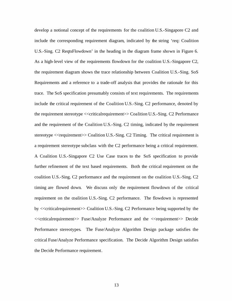
develop a notional concept of the requirements for the coalition U.S.-Singapore C2 and
include the corresponding requirement diagram, indicated by the string ‘req: Coalition
U.S.-Sing. C2 ReqtsFlowdown’ in the heading in the diagram frame shown in Figure 6.
As a high- level view of the requirements flowdown for the coalition U.S.-Singapore C2,
the requirement diagram shows the trace relationship between Coalition U.S.-Sing. SoS
Requirements and a reference to a trade-off analysis that provides the rationale for this
trace. The SoS specification presumably consists of text requirements. The requirements
include the critical requirement of the Coalition U.S.-Sing. C2 performance, denoted by
the requirement stereotype <<criticalrequirement>> Coalition U.S.-Sing. C2 Performance
and the requirement of the Coalition U.S.-Sing. C2 timing, indicated by the requirement
stereotype <<requirement>> Coalition U.S.-Sing. C2 Timing. The critical requirement is
a requirement stereotype subclass with the C2 performance being a critical requirement.
A Coalition U.S.-Singapore C2 Use Case traces to the SoS specification to provide
further refinement of the text based requirements. Both the critical requirement on the
coalition U.S.-Sing. C2 performance and the requirement on the coalition U.S.-Sing. C2
timing are flowed down. We discuss only the requirement flowdown of the critical
requirement on the coalition U.S.-Sing. C2 performance. The flowdown is represented
by <<criticalrequirement>> Coalition U.S.-Sing. C2 Performance being supported by the
<<criticalrequirement>> Fuse/Analyze Performance and the <<requirement>> Decide
Performance stereotypes. The Fuse/Analyze Algorithm Design package satisfies the
critical Fuse/Analyze Performance specification. The Decide Algorithm Design satisfies
the Decide Performance requirement.

14
Figure 6. Coalition U.S.-Singapore SoS requirement diagram.
A use case specifies a sequence of actions a system performs. A use case diagram
shows the relationships among actors, the system, and use cases. Figure 7 displays the
use case diagram for the MDP SoS problem description. As indicated by the MDP SoS
description, triggered by intelligence messages from ‘Intel Agency’ actor followed by
ship manifests from ‘Ship Companies’ actor, and provided with weather reports from
‘Weather Center’ actor, the coalition SoS performs a sequence of actions indicated by the
use cases − Receive & Process Intel, Receive & Process Ship Manifests, Fuse Interl and
Ship Manifests, Receive & Process Weather Reports, Track Threats, Process Radar Data,
and Form COP. In addition, Figure 8 shows the use case diagram corresponding to the
‘Coalit ion U.S.-Sing. C2’. The additional actors are the Singapore center and the U.S. C2

15
center, which provide status and radar reports to the coalition C2. The Form and Send
Alert Messages use case is supported, through <<include>>, by the Process Intel,
Process Ship Manifests, and Fuse Intel and Ship Manifest use cases. Likewise, the
Formulate and Disseminate COP use case is supported by the Process Radar Reports and
Status, Fuse Radar Reports and Status, and Process Weather Reports.
Figure 7. Coalition U.S.-Sing. SoS use case diagram.

16
Figure 8. Coalition U.S.-Sing. C2 use case diagram.
An activity is a behavior or a function composed of actions, which may invoke other
activities. Activity diagrams are dynamic, behavioral constructs used in SysML
behavioral diagrams. The activity diagrams and Enhanced Functional Flow Block
Diagrams (EFFBD) [SysML Partners, 2005, and Block, 2006] are similar, but the
terminology and notation are different. The activity diagram for the Coalition U.S.-
Singapore SoS depicts the functions that are performed by the various parts of the
systems comprising the SoS. The inputs and outputs to the functions are indicated. As
shown in Figure 9, the SysML activity diagram allows modeling of the SoS at the
functional level. The components of the coalition SoS perform the activities represented
by the parts labeled with the functions they perform. The connectivity and data flow are

17
shown by the solid lines connecting the ports attached to the various parts. Both
continuous and discrete flows are shown in the diagram.

18
Figure 9. Coalition U.S.-Singapore SoS − Activity Diagram.

19
A sequence diagram, a dynamic, behavioral constructs used in SysML behavioral
diagrams, specifies interactions in terms of control flow, defined by sending and
receiving messages (control and data) between lifelines. The time ordering of the
messages is indicated by the vertical placement of the message on the diagram. A block
represents a system of the SoS. The sequence diagram in Figure 10 shows data/message
flows between the different blocks representing the systems within the Coalition U.S.-
Singapore SoS and between the Coalition U.S.-Singapore SoS and the systems external to
the SoS (i.e., Intel and ship companies that produce ship manifests). We can also show
interactions among the different parts of the SoS and the environment using a sequence
diagram. The sequence diagram in Figure10, identified by the string ‘seq: Coalition
U.S.-Singapore C2’ in the heading, shows data/message flows between the different
processes within the Coalition U.S.-Singapore C2 and between the Coalition U.S.-
Singapore C2 SoS and the systems external to the SoS (i.e., Intel and ship companies that
produce ship manifests).
A block has been used to represent a component of an SoS. Figure 11 shows the SoS
breakdown or the composition of the coalition SoS in terms of the blocks representing the
systems of the SoS. This representation is similar to that in Figure 5; the only difference
is that blocks are used in Figure 11. SysML defines a stereotype UML class called
<<block>>; block diagrams are thus analogous to class diagrams in UML. Each block is
shown with the attributes and operations. FlowPorts and ServicePorts represent the
entities entering and exiting a block. Figure 12 shows the blocks representing some
systems of the coalition MDP SoS.

20
Figure 10. Sequence Diagram for Coalition U.S.-Singapore C2.
Figure 11. Coalition U.S.-Singapore SoS − System Breakdown.

21
Figure 12. Blocks representing some systems of the coalition MDP SoS.
As in [Osmundson and Huynh, 2005] which emphasizes the utility of UML-based
paper model in the development of an executable model, the work in this paper brings out
the utility of SysML modeling of an SoS in building an executable of the SoS for
simulation for use in systems engineering applications. Again, [Rao et al, 2006] notes the
advantages of SysML over UML in modeling of systems of systems. We believe our
work establishes a direct correspondence between the SysML models and the executable
model used in simulation of the coalition SoS.
Figure 13 points out the direct translation of the OV-1 and the context diagram with
the top layer of the executable SoS model, in this case, the Extend™ model3 of the SoS.
The graphical icons are not part of the Extend™ library of icons; they are icons we
create. The emphasis here is the interactions among the elements of the SoS and the
3 The Extend™ model of the SoS is an adaptation of two Extend™ models, namely, the Bank.mox and SCMA_LAN.mox in Extend, v. 6, developed by Imagine developed by Imagine That!, San Jose, CA, 2003.

22
Intel and Ship Manifests external systems via the coalition network. Each of these
graphical icons is supported by complicated modules that reside in the layer immediate
below the top layer. For example, Figure 14 displays the detail of the coalition C2
module, which captures the connectivity and structural contents of the activity and
sequence diagrams modeling the Coalition U.S.-Sing. C2 discussed above. Figure 15
simply shows the third layer of the Extend™ SoS model.
Figure 16 contains the assumed characteristics (probability distributions) of the
messages generated by the different components of the coalition SoS. As shown, more
PAVs, meaning more traffic (messages per second) imposed on the coalition network,
more utilization of the network.
The crux of this is that an executable can be built directly from the SysML model of
the SoS. The executable model can be used for many systems engineering applications.
Figure 13. Extend™ Model of the MDP SoS.

23
Figure 14. Extend™ Module of Coalition U.S.-Singapore C2.
Figure 15. Lower-Level Coalition C2 Extend™ Modules − Logic.

24
Figure 16. Some simulation results.
4. CONCLUSION
A systems engineering methodology for analyzing systems of systems (SoS)
elucidated in this paper involves the use of process modeling, the SysML tool, and the
subsequent conversion of the SysML model of an SoS into an end-to-end system of
systems executable object-oriented simulation model. This paper illustrates the use of
SySML to model a coalition SoS and its utility in allowing a direct mapping to an
executable model (in this case, an Extend™ model). We present an exploratory
application to analysis of a coalition MDP SoS. Our ongoing future work is aimed at
extending the methodology and improving its rigor and tying it to ontological
engineering. We also recognize a need for more SysML applications in modeling
systems and SoS in order to bring out the advantages of SysML and to identify any
features that are still missing.
25
REFERENCES
C. Bock, SysML and UML 2 Support for Activity Modeling, Systems Engineering, Vol.
9, No. 2, 2006, pp. 160-186.
M. Hause and F. Thom, Rebuilding the Tower of Babel − The case for UML with Real-
time Extensions, INCOSE Spring Symposium 2001, May 14-16, INCOSE UK
Chapter.
T.V. Huynh, Maritime Domain Protection Systems Engineering & Integration, Maritime
Domain Protection Task Force Symposium Proceedings, 18-19 August 2004, Naval
Postgraduate School.
T.V. Huynh, J.S. Osmundson, and P. Shaw, Research in Maritime Domain
Awareness/Maritime Domain Protection/Metrification of the Littorals
(DA/MDP/MoL), Presentation to OUSD(AT&L), February 7, 2006.
J. Buschmann, T. Crider, G. Ferraris, E. Garcia, H. Gungor, S. Hoffmann, M. Kelley, C.
MacCumbee, R. Malloch, C. McCarthy, J. McIlvaine, D. Rummler, S. Sari, T. N.
Teo, D. Walton, Jr., W. Westmoreland, M. Wiens, A. Wise, G. Woelfel, R. Wyllie, H.
H. Ang, K. M. Chang, C. Chua, D. Cfir, K.H. Er, Y.S. How, Y.C. Hsu, W.T. Khoo,
S.J. Koh, R.Kratzer, L. Liang, J. Lim, T.L. Lim, J. Lorio, J. Lukacs, C.M. Ng, W.
Ong, C.K. Quek, D. Raghavan, M. Tan, N.K. Tan, A. Teo, H.S. Teo, M. Tong, K.H.
Yeoh, Y.C. Yong, Maritime Domain Protection in the PACOM AOR, Report
prepared for the Deputy Chief of Naval Operations for Warfare Requirements and
Programs (OPNAV N7), 2000 Navy Pentagon, Rm. 4E92, Washington, DC 20350-
2000, June 2005.

26
J. S. Osmundson, R. Gottfried, Y. K. Chee, H. B. Lau, W. L. Lim, P. S.W. Poh, and C. T.
Tan, Process Modeling: A Systems Engineering Tool for Analyzing Complex
Systems, Systems Engineering, Vol. 7, No. 4, 320-337, 2004.
J. S. Osmundson and T.V. Huynh, A Systems Engineering Methodology for Analyzing
Systems of Systems, Proceedings of 1st Annual System of Systems Engineering
Conference, Johnstown, PA, June 13 – 14, 2005.
M. Rao, S. Ramakrishnan, and C. Dagli, Modeling Net-centric System of Systems Using
the Systems Modeling Language, Proceedings of the Fourth Annual Conference on
Systems Engineering Research, Los Angeles, CA, April 7-8, 2006.
SysML Partners, SysML Specification v. 0.90 and Systems Modeling Language
(SysML), 3rd Revised OMG Submission (draft), 2 February 2005.
BIOGRAPHIES
Dr. Tom Huynh is an associate professor of systems engineering at the Naval Postgraduate School in Monterey, CA. His research interests include uncertainty management in systems engineering, complex systems and complexity theory, system scaling, simulation-based acquisition, and system-of-systems engineering methodology. Prior to joining the Naval Postgraduate School, Dr. Huynh was a Fellow at the Lockheed Martin Advanced Technology Center, where he engaged in research in computer network performance, computer timing control, bandwidth allocation, heuristic algorithms, nonlinear estimation, perturbation theory, differential equations, and optimization. He was also a lecturer in the Mathematics department at San Jose State University. Dr. Huynh obtained simultaneously a B.S. in Chemical Engineering and a B.A. in Applied Mathematics from UC Berkeley and an M.S. and a Ph.D. in Physics from UCLA.

27
John Osmundson is an associate professor with a joint appointment in the Systems Engineering and Information Sciences Departments at the Naval Postgraduate School in Monterey, CA. His research interest is applying systems engineering and computer modeling and simulation methodologies to the development of system architectures, performance models, and system trades of time-critical information systems. Prior to joining the Naval Postgraduate School in 1995 Dr. Osmundson worked for 23 years at Lockheed Missiles and Space Company (now Lockheed Martin Space Division) in Sunnyvale and Palo Alto, CA, as a systems engineer, systems engineering manager, and manager of advanced studies. Dr. Osmundson received a B.S. in physics from Stanford University and a Ph.D. in physics from the University of Maryland.