a taxonomy of clock synchronization algorithms
TRANSCRIPT

I R
I S
AIN
STIT
UT D
E R
EC
HER
CH
E E
N IN
FO
RM
ATIQUE E
T SYSTÈMES ALÉATOIRES
P U B L I C A T I O NI N T E R N ENo
I R I S ACAMPUS UNIVERSITAIRE DE BEAULIEU - 35042 RENNES CEDEX - FRANCEIS
SN
116
6-86
87
1103
A TAXONOMY OF CLOCK SYNCHRONIZATION
ALGORITHMS
EMMANUELLE ANCEAUME AND ISABELLE PUAUT

INSTITUT DE RECHERCHE EN INFORMATIQUE ET SYSTEMES ALEATOIRES
Campus de Beaulieu – 35042 Rennes Cedex – FranceTel. : (33) 02 99 84 71 00 – Fax : (33) 02 99 84 71 71
http://www.irisa.fr
A Taxonomy of Clock Synchronization AlgorithmsEmmanuelle Anceaume and Isabelle PuautTh�eme 1 | R�eseaux et syst�emesProjet SolidorPublication interne n�1103 | Juillet 1997 | 25 pagesAbstract: Clock synchronization algorithms ensure that physically dispersed proces-sors have a common knowledge of time. This paper proposes a taxonomy adapted to allpublished software fault-tolerant clock synchronization algorithms: deterministic and prob-abilistic, internal and external, and resilient from crash to Byzantine failures. We classifyclock synchronization algorithms according to their internal structure and to three othogo-nal and independent basic building blocks. Our taxonomy will help the designer in choosingthe most appropriate structure of algorithm and the best building blocks suited to his/herhardware architecture, failure model, quality of synchronized clocks and message cost in-duced. Moreover, our classi�cation uses a uniform notation that allows to compare existingclock synchronization algorithms with respect to their fault model, the building blocks theyuse, the properties they ensure and their cost in terms of message exchanges.Key-words: Clock synchronization, distributed systems, real-time systems, deterministic,probabilistic (R�esum�e : tsvp)This work is partially supported by the french Department of Defense (DGA/DSP),#96.34.106.00.470.75.65.Centre National de la Recherche Scientifique Institut National de Recherche en Informatique
(UPRESSA 6074) Universite de Rennes 1 – Insa de Rennes et en Automatique – unite de recherche de Rennes
Une Classi�cation des Algorithmes de Synchronisationd'HorlogesR�esum�e : Les algorithmes de synchronisation d'horloges o�rent une notion commune dutemps �a des processeurs n'ayant pas acc�es �a une horloge globale partag�ee. Ce rapport pro-pose une classi�cation adapt�ee �a tous les algorithmes de synchronisation d'horloges �evoluantdans un environnement sujet aux d�efaillances, qu'ils soient d�eterministes ou probabilistes,et qu'ils assurent une synchronisation interne ou externe. Les algorithmes de synchronisa-tion d'horloges �etudi�es sont class�es selon leur structure interne et selon trois blocs de baseind�ependants. Cette classi�cation est con�cue pour guider le concepteur d'un algorithme desynchronisation d'horloges dans le choix de l'algorithme le mieux adapt�e �a son architecturemat�erielle, le mod�ele de d�efaillances vis�e, la qualit�e de la synchronisation obtenue ainsi quele cout r�esultant en terme de nombre de messages �echang�es. Par ailleurs, la classi�cationpropos�ee utilise une notation uniforme, qui permet de comparer les algorithmes existantsselon le mod�ele de fautes qu'il supportent, les blocs de base qu'ils utilisent, les propri�et�esqu'ils assurent et le cout associ�e.Mots cl�es : Synchronisation d'horloges, syst�emes distribu�es, syst�emes temps-r�eel, d�eter-ministe, probabiliste

A Taxonomy of Clock Synchronization Algorithms 31 IntroductionA distributed system consists of a set of processors that communicate through message ex-changes and do not have access to a global clock. Nonetheless, an increasing number ofdistributed applications, such as process control applications, transaction processing appli-cations, or communication protocols, require that synchronized clocks be available to haveapproximately the same view of time. Time in this context means either an approximationof real time or simply an integer-valued counter. The algorithms ensuring that physicallydispersed processors have a common knowledge of time are called clock synchronizationalgorithms.Designing clock synchronization algorithms presents a number of di�culties. First, dueto variations of transmission delays each process cannot have an instantaneous global viewof every remote clock value. Second, even if all clocks could be started at the same realtime, they would not remain synchronized because of drifting rates. Indeed, clocks run at arate that can di�er from real time by 10�5 seconds per second and thus can drift apart byone second per day. In addition, their drift rate can change due to temperature variationsor aging. Finally, the most important di�culty is to support faulty elements, which arecommon in distributed systems.Clock synchronization algorithms can be used to synchronize clocks with respect toan external time reference and/or to synchronize clocks among themselves. In the �rstcase, called external clock synchronization, a clock source shows real time and the goalfor all clocks is to be as close to this time source as possible. In the second case, calledinternal clock synchronization, real time is not available from within the system, and thegoal is then to minimize the maximum di�erence between any two clocks. An internal clocksynchronization algorithm enables a process to measure the duration of distributed activitiesthat start on one processor and terminate on another one. It establishes an order betweendistributed events in a manner that closely approximates their real time precedence.Clock synchronization may be achieved either by hardware or by software. Hardwareclock synchronization [SR87, KO87] achieves very tight synchronization through the useof special synchronization hardware at each processor, and uses a separate network solelyfor clock signals. In contrast, software clock synchronization algorithms [CAS86, HSSD84,ST87, LL88, LMS85, VCR97, PB95, GZ89, MS85, FC95a, FC97, OS94, Arv94, Cri89] usestandard communication networks and send synchronization messages to get the clocks syn-chronized. They do not require speci�c hardware, but do not provide synchronization astight as hardware algorithms. Software clock synchronization algorithms decompose them-selves in deterministic, probabilistic and statistical algorithms. Deterministic algorithmsPI n�1103

4 Emmanuelle Anceaume and Isabelle Puautassume that an upper bound on transmission delays exists. They guarantee an upper boundon the di�erence between any two clock values (precision). Probabilistic and statistical clocksynchronization algorithms do not make any assumptions about maximum message delays.While probabilistic algorithms do not assume anything on delay distributions, statisticalalgorithms assume that the expectation and standard deviation of the delay distributionsare known. In contrast to deterministic clock synchronization algorithms, probabilistic andstatistical algorithms guarantee a constant maximum deviation between any clock valueswith a probability strictly less than one. In probabilistic algorithms, a clock knows at anytime if it is synchronized or not with the others, whereas in statistical algorithms, clocks donot know how far apart they are from each others.Clock synchronization has been extensively studied for the last twenty years. Thoroughsurveys can be found in [Sch86, RSB90] and [SWL90]. In [RSB90], software and hardwareclock synchronization algorithms are classi�ed with regard to the clock correction schemeused. In contrast, the algorithms surveyed in [SWL90] are listed according to the suppor-ted faults and the system synchrony (i.e., knowledge of upper bounds on communicationlatencies). Schneider's work [Sch86] gives a single unifying paradigm and correctness proofthat can be used to understand mostly all deterministic clock synchronization algorithmssupporting Byzantine failures.Our work extends these surveys by proposing a taxonomy adapted to all published soft-ware fault-tolerant clock synchronization algorithms: deterministic, probabilistic and statis-tical, internal and external, and resilient from crash to Byzantine failures. Our taxonomyis more precise than existing classi�cations in the sense that all algorithms are classi�edaccording to a larger set of parameters: system synchrony, failure model, structure of thealgorithm and basic building blocks. Our taxonomy should help the designer in choosing themost appropriate structure of algorithm and the best building blocks suited to his/her hard-ware architecture, failure model, quality of synchronized clocks and message cost induced.In addition, we use a uniform notation that allows the comparison between all algorithmswith respect to the assumptions they make, the building blocks they use, the propertiesthey ensure and their cost in terms of number of messages exchanged. Note that we arenot concerned in this paper with algorithms aimed at maintaining logical clocks that re ectproperties on the execution of distributed applications, such as causal relationships [Lam78].In addition, for space considerations, we do not detail issues speci�c to clock synchronizationin large scale distributed systems (e.g. [SR87, VCR97]).We classify clock synchronization algorithms according to their internal structure (sym-metry of the algorithm) and to three orthogonal and independent basic building blocks weIrisa

A Taxonomy of Clock Synchronization Algorithms 5have identi�ed. The �rst building block, called the resynchronization event detection block ,aims at detecting the instant at which processors have to resynchronize their clock. Thesecond one, called the remote clock estimation block, estimates the values of remote clocks.The third one, called the clock correction block is designed to correct each logical clock ac-cording to the result provided by the remote clock estimation block. Each building block inour taxonomy is illustrated with algorithms relying on it.The remainder of this paper is organized as follows. Section 2 describes the underlyingsystem upon which clock synchronization algorithms are based. A precise statement of theproblem to be solved is given in Section 3. The proposed classi�cation of clock synchroniza-tion algorithms is introduced in Section 4. Finally, a summary of the characteristics of themost referenced algorithms is proposed in Section 5.2 System modelThe study of any clock synchronization algorithm requires a precise description of the un-derlying distributed system, concerning its overall structure (Section 2.1), the timing as-sumptions of its network (Section 2.2) and the failure mode of its components (Section2.3).2.1 Processors, network and clocksWe consider a set P = fp1; p2; :::; png of processors interconnected by a communication net-work. According to the algorithms, the network can have di�erent characteristics (broadcastvs point-to-point, fully-connected or not). Unless explicitly stated, a fully connected networkis assumed throughout this paper.With each processor pi 2 P we associate a local hardware clock Hpi . It generally consistsof an oscillator and a counting register that is incremented by the ticks of the oscillator.While clocks are discrete, all algorithms assume that clocks run continuously, i.e., Hpi isa continuous function on some real-time interval. Moreover, although hardware clocks candrift apart from real time due to temperature changes and aging, it is commonly assumedthat their drift is within a narrow envelope of real-time, as expressed below:Assumption 1 (�-bounded clock) For a very small known constant � > 0, we de�ne ahardware clock Hpi(t) to be �-bounded provided that for all real time t:1(1 + �) � dHpi(t)dt � (1 + �)PI n�1103
6 Emmanuelle Anceaume and Isabelle Puautwith Hpi(t) denoting the value of the hardware clock of processor pi at real-time t. Notethat throughout this paper, lower case letters represent real times and upper case lettersclock times.Clock synchronization algorithms do not directly synchronize local hardware clocks. Ra-ther, they introduce logical clocks . The value of a logical clock at real-time t, denotedLpi(t), is determined by adding an adjustment term, denoted Api(t), to the local hardwareclock Hpi(t). The adjustment term Api(t) can either be a discrete value changed at eachresynchronization [SC90, ST87] or a linear function of time [SC90, Cri89].In order to implement external synchronization algorithms, some processors use the GPS(Global Positioning System) or radio receivers to obtain the time signal broadcast by astandard source of time, as the UTC (Universal Time Coordinated). Such processors arecalled reference clocks . In external clock synchronization algorithms, every reference timeprocessor pr has a hardware clock Hpr approximating real time at any point within some apriori given error � (see assumption 2 below).Assumption 2 (Bounded external deviation) A reference clock Hpr is correct at timet ifj Hpr (t)� t j� �2.2 Network synchronyIn distributed systems, message delays may be more or less predictable depending on thetype of network used and the assumptions made on the network load. Some designers assumethat known lower and upper bounds to deliver (i.e. send, transport and receive) a messageexist. This is formalized below:Assumption 3 (Bounded transmission delay) The real time delay to send, transport,and receive any message over any link is within some known bounds [� � �; � + �].When such an assumption holds, clock synchronization algorithms ensure that all correctlogical clocks are within a maximum distance from each other (this distance is called thealgorithm precision). Algorithms guaranteeing a precision are called deterministic clocksynchronization algorithms.On the other hand, it can be assumed that such tight bounds do not exist, for instancedue to tra�c overload. According to designers, it may be assumed either that message delaysare modeled as a variable with arbitrary values, or that the mean and standard deviation oftransmission delays are known. In the former case, we are dealing with probabilistic clockIrisa
A Taxonomy of Clock Synchronization Algorithms 7synchronization algorithms, although the assumptions made in the latter case are those ofstatistical clock synchronization algorithms. In both cases, the precision of any two correctlogical clocks can only be guaranteed with some non-null probability.2.3 Failure modeFailures can be de�ned as deviations from a correct behavior. All components (processors,communication links, and clocks) may commit failures. Following is a list of types of proces-sor, link and clock failures that have mostly been assumed throughout clock synchronizationalgorithms.Concerning clocks, most of the algorithms [HSSD84, ST87, LL88, LMS85, VCR97, PB95,MS85, FC95a, FC97] assume uncontrolled failures (also called Byzantine or arbitrary fai-lures). Other ones, such as [GZ89] assume timing failures. , a more restricted failure modeprohibiting con icting information.Clock timing failure: [CASD85] A local hardware clock commits a timing failure if itdoes not meet assumption 1, i.e., is not �� bounded.Clock Byzantine failure: [LSP82] A local hardware clock commits a Byzantine failurewhen it gives inaccurate, untimely or con icting information. This includes dual-facedclocks, which may give di�erent values of time to di�erent processors.The failure semantics of processors assumed in published algorithms cover nearly all thekinds of failures ever identi�ed. More precisely, processors may crash as in [VCR97, CAS86,GZ89, OS94], commit performance failures as in [VCR97, CAS86, Cri89] or more generally,commit Byzantine failures as in [HSSD84, ST87, LL88, LMS85, PB95, MS85, FC95a, FC97].Processor crash failure: [CASD85] A processor commits a crash failure if it behavescorrectly and then stops executing forever (permanent failure).Processor performance failure: [CASD85] A processor commits a performance failureif it completes a computation step in more than the speci�ed value.Processor Byzantine failure: [LSP82] A processor commits a Byzantine failure if itexecutes uncontrolled computation.With regard to the network, whatever its type (broadcast or point-to-point), the failuresemantics are more restricted. A link may commit omission or performance failures asassumed in [CAS86, GZ89, VCR97, HSSD84], but never be partitioned (the network nevercrashes).PI n�1103

8 Emmanuelle Anceaume and Isabelle PuautLink omission failure: A link l from a processor pi to a processor pj commits an omissionfailure on a message m if m is inserted into pi's outgoing bu�er but l does not transportm into pj 's incoming bu�er.Link performance failure: A link commits a performance failure if it transports somemessage in more time than its speci�ed bound. Obviously, this applies only to systemswith known upper and lower bounds on network latencies.Recall that the message delay consists of the time needed for the sender to send it, totransport it, and for the receiver to deliver it. Thus a violation of assumption 3 may be dueto a performance failure of the sender, the receiver, or the link between them.If a component (clock, processor or link) commits a failure, we say that it is faulty ;otherwise it is correct . Most algorithms assume a bound on the total number of faultycomponents (processors, clocks, communication links), as stated in assumption 4.Assumption 4 (Bounded number of faulty components) There are at most f faultycomponents in the system during the execution of the clock synchronization algorithm, withf a positive integer1.3 The clock synchronization problemGiven the system model presented in Section 2, a clock synchronization algorithm aims atsatisfying the following property for all correct clocks i and j and all real time t:Property 1 (Agreement) j Lpi(t) � Lpj (t) j� , where is called the precision of theclock synchronization algorithm.This property informally states that correct logical clocks are approximately equal. Alldeterministic clock synchronization algorithms meet this property, contrary to probabilisticand statistical ones that satisfy this property with a probability strictly less than one.While the agreement property is obviously required, it is not a su�cient condition. Forexample, this property holds even if all logical clocks are simply set to zero and stopped. Inorder to rule out such trivial solutions, [LMS85] introduced the property given below:Property 2 (Bounded correction) There is a small bound � on the amount by which acorrect clock is changed at each resynchronization.1The value of f depends on the failure mode assumed. For instance, to tolerate f processor Byzantinefailures without authenti�cation, f must satisfy f � n3 , with n the number of processors [LL84]. Irisa
A Taxonomy of Clock Synchronization Algorithms 9Another way to rule out trivial solutions is to require that logical clocks are permanentlywithin a narrow envelope of real time (property 3).Property 3 (Accuracy) For any correct processor pi 2 P, and for any real-time t, thereexists a constant �, called accuracy, such that for any execution of the clock synchronizationalgorithm, (1 + �)�1t + a � Lpi(t) � (1 + �)t + b, with a and b some constants dependingon the initial condition of the algorithm.This property is equivalent to the (�1; �2; �3)-validity property introduced by Lundeliusand Lynch in [LL88], and is termed bounded drift rate in [FC97]. The best accuracy �achievable (and achieved in [ST87]) is equal to the underlying hardware clock drift � (optimalaccuracy).Finally, deterministic external clock synchronization algorithms have to bound the de-viation between a correct logical clock and real time by an a priori given constant '. Thisis expressed in the following property:Property 4 (Bounded external deviation) For any correct processor pi 2 P, and anyreal time t, j Lpi(t)� t j� '.Notice that some clock synchronization algorithms may impose the following assumptionconcerning clocks initial synchronization (see [LL88]):Assumption 5 (Initial synchronization) For any two correct processors pi and pj, ifT0 is the logical time at which pi and pj start the synchronization algorithm, then jli(T0)�lj(T0)j � �, with li(T0) (resp. lj(T0)) the real-time when pi (resp. pj) logical clock showsT0, and � a real-time value.4 A taxonomy of clock synchronization algorithmsThis section is devoted to the proposed classi�cation of clock synchronization algorithms.We classify clock synchronization algorithms according to two orthogonal features: theirinternal structure (Section 4.1) and the basic building blocks from which the algorithmsare built (Section 4.2). Three building blocks have been identi�ed and correspond to thethree successive steps executed by every clock synchronization algorithm. Building blocksare generic in the sense that they apply to all clock synchronization algorithmsPI n�1103
10 Emmanuelle Anceaume and Isabelle Puaut4.1 Structure of the clock synchronization algorithmClock synchronization algorithms may be either symmetric or asymmetric. In symmetricalgorithms all processors play the same role, whereas in asymmetric algorithms one pre-de�ned processor, called the master, has a speci�c role. The symmetry of the algorithmmainly in uences its ability to support failures, and its cost in term of number of mes-sages exchanged to achieve the sought precision. Notice that in [MS85, FC95a, FC97], and[LMS85] (algorithms CON and COM), the choice of the structure of the algorithm is left toits designer.4.1.1 Symmetric schemesIn symmetric algorithms, each processor plays the same role and executes the whole clocksynchronization algorithm. Each processor pi 2 P disseminates clock synchronization mes-sages to every other one, and uses the messages received from the remote processors tocorrect its clock. Symmetric algorithms can be split into two classes, ooding-based andring-based, depending on the virtual path taken for transmitting a message from every pro-cessor to every other one.In ooding-based symmetric algorithms, each processor sends its messages to all outgoinglinks. Messages received on incoming links are relayed when a non fully connected network isused. A ooding-based technique is used in the algorithms [CAS86, HSSD84, ST87, LL88,VCR97, PB95] and [LMS85] (algorithm CSM). The bene�t of ooding-based techniquesis their natural support for fault tolerance, as they do not exhibit a single point of failure.However, they may require up to n2 messages to disseminate a clock synchronization messageto all processors in P . This large number of messages can be lowered to n if a broadcastnetwork is used [VCR97].The virtual ring scheme was proposed in [OS94] to decrease the number of exchangedmessages experienced in ooding-based schemes. In the ring scheme, all processors in Pare gathered along a virtual ring. The number of messages is reduced by sending only onemessage along this cyclic path. As this message travels along the ring, each processor addsits own data to the message. Compared with ooding-based schemes, virtual ring schemesneed to exchange a smaller number of messages (only n messages per resynchronization areused), but need extensions in order to support processor and network failures.Irisa

A Taxonomy of Clock Synchronization Algorithms 114.1.2 Asymmetric schemesIn asymmetric schemes, also called master-slave schemes, processors involved in the clocksynchronization algorithm play di�erent roles. One processor in P is designed as the master ,and the other processors are designed as the slaves . Within this scheme, two variants exist.In the former one, called master-controlled scheme [GZ89], the master acts as a coordinatorof the clock synchronization algorithm. It collects the slaves clocks, estimates them andsends them back the corrected clock values. In the latter variant, commonly called slave-controlled scheme, the master acts as a reference processor providing time with respect towhich all the slaves resynchronize [Cri89, Arv94].The obvious advantage of asymmetric schemes is their low cost in terms of number ofmessages exchanged. On the other hand, the presence of the master represents a singlepoint of failure, and needs some extra mechanisms, such as fault detection or election of anew master to be avoided. Another drawback of the asymmetric scheme is the presence ofa single master that can be swamped by a large number of synchronization messages, thusinvalidating in some way the assumptions made on the communication delays.4.2 Clock synchronization building blocksIn any clock synchronization algorithm | whatever its structure is | each processor pi 2 Phas to achieve three successive steps. First, it has to detect the instant at which it mustresynchronize, which is done by invoking the resynchronization event detection block (Sec-tion 4.2.1). Second, it has to estimate the value of remote logical clocks, which is achievedby invoking the remote clock estimation block (Section 4.2.2). Third, it has to apply a cor-rection on its logical clock according to the result of the second step. The clock correctionblock (Section 4.2.3) is devoted to this task. Investigation of existing clock synchronizationalgorithms led us to the identi�cation of a palette of techniques implementing these buil-ding blocks. Unless explicitly stated, all the techniques implementing each building blockare suited to all types of algorithms (deterministic, probabilistic or statistical, internal orexternal, symmetric or not).4.2.1 Resynchronization event detection blockThe objective of pi's resynchronization event detection block is to trigger a resynchroniza-tion event informing processor pi to start the clock synchronization algorithm. Indeed, dueto clock drifts, clocks must be re-synchronized often enough to guarantee the agreementproperty. A common way to resynchronize clocks is to periodically trigger the clock syn-PI n�1103

12 Emmanuelle Anceaume and Isabelle Puautchronization algorithm, and thus to consider the algorithm as a round-based algorithm, eachround being devoted to the resynchronization of all clocks. The di�culty arises when dealingwith the time at which rounds must start. So far, two techniques have been devised. The�rst one used in [LL88, LMS85, PB95] relies on initially synchronized clocks. The second oneadopted in [CAS86, HSSD84, ST87, VCR97] uses message exchanges. These two techniquesare presented in the following paragraphs.Detection technique based on initially synchronized clocksThe mostly used technique is to assume initially �-synchronized clocks (assumption 5) todetect round boundaries. When using such a technique, processor pi considers that a newround k begins when its logical clock reaches time kR, where R is the round duration, i.e.,the time between two successive resynchronizations measured in logical time units, and k isan integer � 1.Intuitively, to keep logical clocks as closely synchronized as possible, � and R must be assmall as possible. However, Lundelius and Lynch prove in [LL88] that R cannot be arbitrarilysmall to be able to distinguish between successive rounds. For instance, in [LL88], we musthave 2(1+�)(�+�)+(1+�) max(�; �+�)+�� < R � �=(4�)��=���(�+�+�)�2����2�.Detection technique based on message exchangesAs mentioned in [LMS85], the precision achieved by algorithms based on ��synchronizedclocks is very sensitive to the initial clock synchronization value �. Another way to detectthe beginning of a round consists for a processor in sending a message to all processors in Pas soon as its logical clock reaches the prede�ned value kR. Upon receipt of such a message,processor pi 2 P starts a new clock synchronization round. Clearly, as rounds are triggeredupon message receipt, the precision of algorithms depends on message latencies [CAS86,HSSD84, ST87]. By using broadcast networks, exhibiting a small variance of transmissiondelays, precision can be improved [VCR97].4.2.2 Remote clock estimation blockThe objective of the remote clock estimation block is to get some knowledge about thevalue of remote clocks. Indeed, due to the presence of non-null and variable communicationdelays and clock drifts, getting an exact knowledge of a remote clock value is not feasible.Thus, only estimates of remote clock values can be acquired. Processor pi's remote clockestimation block is triggered upon receipt of the resynchronization event generated by pi'sIrisa

A Taxonomy of Clock Synchronization Algorithms 13resynchronization event detection block. The output of pi's remote clock estimation blockis a clock estimation set containing the set of remote clock estimates, and taken as input ofthe local clock correction block.Two techniques can be selected to estimate remote clock values. These techniques, namedTime Transmission (TT) and Remote Clock Reading (RCR) are described hereafter. Somealgorithms ([FC95a, FC97, MS85] and [LMS85] { algorithms CON and COM) deliberatelydo not restrict their algorithm to work with one of these techniques. They only assumethat every remote clock can be estimated with a small bounded error �, the error obviouslydepending on the actual clock estimation technique used.The time transmission (TT) techniqueIn the time transmission (TT) technique, processor pi sends its local clock in a message.The receiving processor pj uses the information carried in this message to estimate pi'sclock. Depending on whether communication delays are bounded or not (assumption 3),two variants exist.The �rst variant is suited to systems with bounded communication delays, and requiresclocks to be initially �-synchronized (assumption 5). In this variant, described in [LL88,DHSS95] and [CAS86], pj sends its message to all processes in P at a �xed local logicaltime, say T. Meanwhile, pj collects messages from the other processors within a particularamount of time measured on its logical clock2. Processor pj stores the local time at whichthese messages are received in its clock estimation set. The receipt time of pi's message isused as an estimate of pi's clock. The interval of time during which pj waits for the messageis chosen just large enough to ensure that pj receives it { in case pi is non faulty. Lengthof this interval equals (1 + �)(� + �+ �). At receipt time, pi's clock belongs to the interval[T + (1� �)(� � �� �); T + (1 + �)(� + �+ �)], thus obtaining a maximum estimation errorof 2(�+ � + ��).In case where communication delays are not bounded, a statistical variant of TT hasbeen identi�ed [OS94, Arv94]. In this variant, the absence of both initially synchronizedclocks and precise upper bounds on the transmission delays are overcome by s successivetransmissions of timestamped synchronization messages. Note that this variant requires theknowledge of the expectation and deviation of transmission delays.Lots of deterministic clock synchronization algorithms [CAS86, HSSD84, ST87, LL88,PB95] and [LMS85] (algorithm CSM) and statistical ones [OS94, Arv94] rely on the TT2According to the structure of the algorithm (symmetric, slave-controlled asymmetric or master-cpntrolledasymmetr ic) and to the failure mode assumed, the number of messages pj must wait for di�ers.PI n�1103

14 Emmanuelle Anceaume and Isabelle Puauttechnique because of its low cost in terms of messages compared with the RCR techniquedescribed hereafter.Remote clock reading (RCR) techniqueThe remote clock reading technique (RCR) has been introduced by [Cri89] to deal with thecase where the upper bound of communication delays is unknown. The RCR techniqueworks as follows. Processor pj willing to estimate the clock of a remote processor pi, sendsa request message to pi, and waits for a certain amount of time pi's response. The responsecontains the current value of pi's logical clock, say T . Processor pj stores T in its clockestimation set . Value T is used as an estimate of pi's clock. Let D be half of the roundtrip delay measured on pj 's clock between the sending of pj 's message and receipt of pi'sresponse. The interval in which pi's clock belongs to, when pj receives pi's message is[T + (� � �)(1� �); T + 2D(1 + 2�)� (� � �)(1 + �)], thus obtaining a maximum estimationerror of 2D(1 + 2�)� 2(� � �).Note that the smaller D is, the smaller the length of the estimation interval is, and thusthe better the remote clock estimate is. Probabilistic clock synchronization algorithms usethis property to obtain a low and known estimation error. If pi wants to have an estimationerror, say �, better than the one obtained with a 2D round trip delay, it sends again itsmessage as long as the response from pj arrives in a minimum of time, say 2U (U < D),with U = (1� 2�)(� + � � �).Bene�ts of the RCR clock estimation technique, used in [Cri89, GZ89, OS94, VCR97],are twofold. First its correctness does not depend on any assumption about the particu-lar shape of the message delay distribution function. Second its correctness does not relyon approximately synchronized clocks. Furthermore, by using this technique, a processorexactly knows the error it makes when estimating a remote clock, and thus knows when ithas lost synchronization with the other processors. However, twice more messages than theTT technique are required due to the use of a request-reply approach.4.2.3 Clock correction blockThe �nal step in a clock synchronization algorithm is to adjust a logical clock in relationwith the other ones. The clock correction block of processor pi takes as input pi's clockestimation set . This block has no output as its e�ect is the correction of pi's logical clock.The adjustment of a logical clock can be done by using either the clock estimates containedin the clock estimation set or the fact that they have been received. In the former case, pi'sadjustment Api is obtained by applying a convergence function to the clock estimation setIrisa
A Taxonomy of Clock Synchronization Algorithms 15(convergence-averaging techniques), while in the latter case (convergence-nonaveraging tech-niques) Api is a value that does not depend on the values contained in the clock estimationset .Convergence-averaging techniquesConvergence-averaging techniques, also called convergence function based techniques, usea so-called convergence function, which takes as arguments the clock estimates containedin the clock estimation set and returns some kind of averaging on these estimates. Anexhaustive list of convergence functions introduced before 1987, is given in [Sch86].In the following, f(pi; x1; � � � ; xn) identi�es a convergence function. Argument pi is theprocessor requesting clock synchronization, and x1; � � � ; xn are the estimated clock valuescontained in pi's clock estimation set.The way the adjustment term Api (see Section 2) is computed di�ers according to thealgorithms. For instance in [LL88], Api is set to T + � � fftm(pi; x1; � � � ; xn), where Tis the time at which the algorithm is started and fftm(pi; x1; � � � ; xn) is the result of theconvergence function fftm(pi; x1; � � � ; xn) applied to the elements of pi'sclock estimation set .There are many possible convergence functions, whose mostly referenced are listed below.For the six following convergence functions (fe, ffca, fftm, fdtm, and fsw) each xi is aninteger value, while for the two last ones (fmm and fim), each xi is an interval.� Interactive convergence function. This function, also known as the Egocentric averagefunction fe is used in [LMS85]. fe(pi; x1; � � � ; xn) returns the average of all argumentsx1 through xn, where xj with 1 � j � n is kept intact if it is no more than $ fromxi and is replaced by xi otherwise. The constant $ has to be selected appropriately.The condition $ > , where is the achievable precision of clocks, must hold to avoidclustering of the clocks, i.e., slow clocks synchronized only to the other slow clockswhile all the fast clocks synchronize only to the other fast clocks. On the other hand,a large $ leads to a reduced quality of the precision as faulty clocks values are notrejected. The advantage of algorithms using convergence function fe is that no sortingalgorithm must be applied to reject faulty clock values.� Fast convergence function. This function used in [MS85, GZ86], and denoted ffc,returns the average of all arguments x1 to xn that are within $ of at least n� f otherarguments. Although ffc yields high quality precision [MS85, GZ86], the complexityof computing all time di�erences to all the other processors of the system is signi�cant.PI n�1103

16 Emmanuelle Anceaume and Isabelle Puaut� Fault tolerant midpoint function. This function, used in [LL88] and denoted fftm,returns the midpoint of the range of values spanned by arguments x1 to xn after the fhighest and the f lowest values have been discarded. fftm is based on the assumptionthat faulty clocks run too fast or too slow, and thus that good clocks will generally liebetween.� Di�erential fault-tolerant midpoint function. This function denoted fdftm, has beenintroduced in [FC95b] and used in [FC97]. fdftm was proven to be optimal with respectto the best precision achievable and the best accuracy (�) achievable for logical clocks(which is not the case with the fftm function). This function is de�ned as follows:fdftm(pi; x1; � � � ; xn) = min(T ��; xl) + max(T +�; xu)2 ;where xl = xhf+1 ; xu = xhn�fwith xh1 � xh2 � xhn ; hi 6= hq ; 1 � hi; hq � nwhere T is pi's logical time and � is the maximum reading error of a distant clock,which has been estimated in [Cri89] to value 2�� + 2�(1 + �) when RCR is used.� Sliding window function. This function, proposed in [PB95], selects a �xed size windowthat contains the larger number of clock estimates. Two convergence functions areproposed; they di�er by the way a window is chosen when multiple windows containthe same number of clock estimates, and by the way the correction term is computedonce the window has been identi�ed. The �rst function, called fdetmean, chooses the �rstwindow, and returns the mean of the clock values contained in the window instance.The second function, called fmedian chooses the window containing clock estimateshaving the smallest variance, and returns the median of all clock estimates within theselected window. The main interest of sliding window convergence functions is thatlogical clocks closeness degrades gracefully when more failures than assumed occur.� Minimization of the maximum error interval-based function. This function takes foreach xi an interval [Li(t)�ei(t); Li(t)+ei(t)], where ei(t) is the maximum error on pi'sclock estimate, and returns an interval for the corrected clock value. More precisely:Si = fxj j consistent(pi; pj)gfmm(pi; x1; � � � ; xn) = [Lm(t)� em(t); Lm(t) + em(t)];where 8i 2 Si; em(t) � ei(t)where consistent(pi; pj) is true if j Lp(t)� Lpj (t) j� epi(t)� epj (t).Irisa
A Taxonomy of Clock Synchronization Algorithms 17� Intersection of the maximum error interval-based function. This function, denoted fim,is similar to fmm in the sense they both take intervals representing clock estimates asarguments. However, fim returns an intersection of the intervals of the clock estimates.Both functions are used in [MO83].Notice that the input of the clock correction block can be reduced to a single clockestimate. In that case, the result of the convergence function (fid) is simply a copy ofthis clock estimate. This can be used for every processor in asymmetric schemes to besynchronized with respect to a single time reference, as in [Cri89] and [Arv94].Convergence-nonaveraging techniquesUnlike convergence-averaging techniques which compute a new clock value by using thecontents of the clock estimation set, convergence-nonaveraging techniques only use the factthat a prede�ned number of remote clocks estimates have been received. The number ofexpected clock estimates depends on the type and the number of tolerated failures. Forinstance, the clock correction block requires that the clock estimation set contains 2f + 1estimates to support f Byzantine failures with no authenti�cation, or f+1 estimates in casewhere authenti�cation is used, or one single estimate in case of performance failures [CAS86].The clock correction block updates the logical clock with a value that di�ers accordingto the algorithms. The logical clock is set to kR+ � in [ST87], to kR in [CAS86, HSSD84],where k is the round number, R is the round duration and � is a constant. In [VCR97], thelogical clock is set to the value of one of the clock estimates contained in the clock estimationset.5 Illustration of the taxonomy and conclusionThis section illustrates our taxonomy on a long (but not exhaustive) list of the most refe-renced deterministic, probabilistic and statistical clock synchronization algorithms. By lackof space, we cannot a�ord to present a full description of each algorithm according to ourtaxonomy. However, we present in Section 5.1 their structure and building blocks and inSection 5.2, their performance and cost.5.1 Classi�cation of clock synchronization algorithmsTable 1 presents the classi�cation of the most referenced clock synchronization algorithms.This table shows that all the clock synchronization algorithms, whatever their type, can bePI n�1103
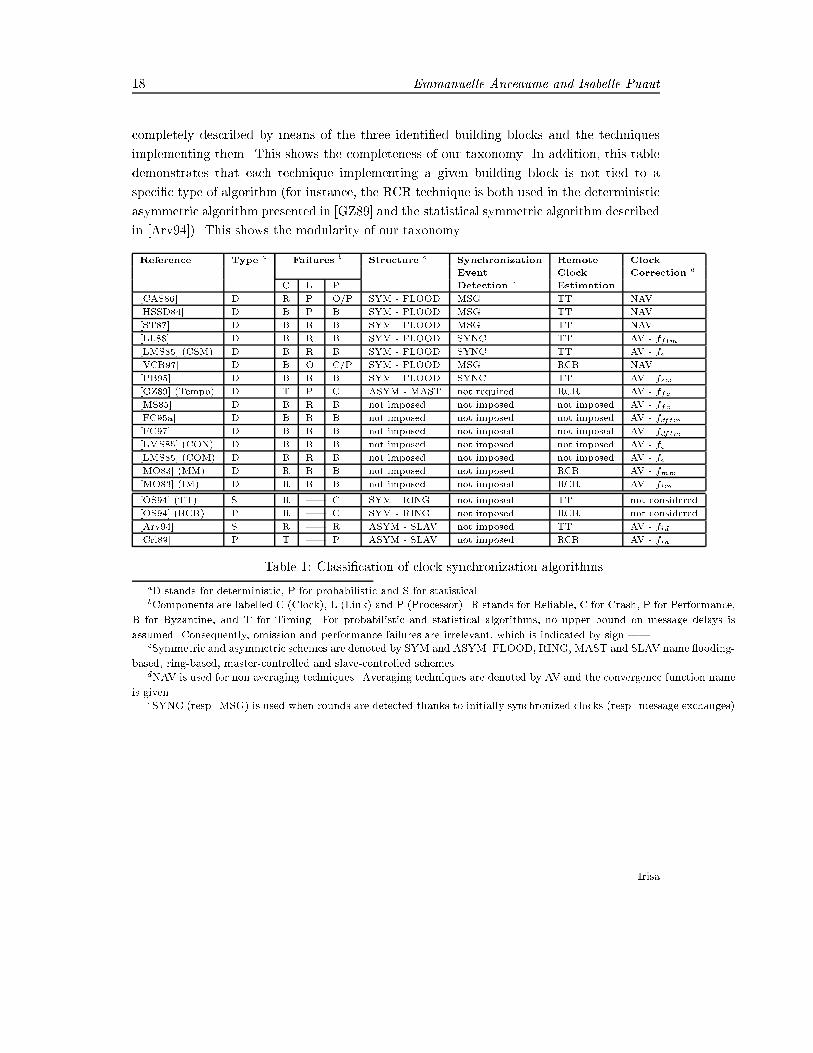
18 Emmanuelle Anceaume and Isabelle Puautcompletely described by means of the three identi�ed building blocks and the techniquesimplementing them. This shows the completeness of our taxonomy. In addition, this tabledemonstrates that each technique implementing a given building block is not tied to aspeci�c type of algorithm (for instance, the RCR technique is both used in the deterministicasymmetric algorithm presented in [GZ89] and the statistical symmetric algorithm describedin [Arv94]). This shows the modularity of our taxonomy.Reference Type a Failures b Structure c Synchronization Remote ClockEvent Clock Correction dC L P Detection e Estimation[CAS86] D R P O/P SYM - FLOOD MSG TT NAV[HSSD84] D B P B SYM - FLOOD MSG TT NAV[ST87] D B R B SYM - FLOOD MSG TT NAV[LL88] D B R B SYM - FLOOD SYNC TT AV - fftm[LMS85] (CSM) D B R B SYM - FLOOD SYNC TT AV - fe[VCR97] D B O C/P SYM - FLOOD MSG RCR NAV[PB95] D B R B SYM - FLOOD SYNC TT AV - fsw[GZ89] (Tempo) D T P C ASYM - MAST not required RCR AV - ffc[MS85] D B R B not imposed not imposed not imposed AV - ffc[FC95a] D B R B not imposed not imposed not imposed AV - fdftm[FC97] D B R B not imposed not imposed not imposed AV - fdftm[LMS85] (CON) D B R B not imposed not imposed not imposed AV - fe[LMS85] (COM) D B R B not imposed not imposed not imposed AV - fe[MO83] (MM) D R R B not imposed not imposed RCR AV - fmm[MO83] (IM) D R R B not imposed not imposed RCR AV - fim[OS94] (TT) S R | C SYM - RING not imposed TT not considered[OS94] (RCR) P R | C SYM - RING not imposed RCR not considered[Arv94] S R | R ASYM - SLAV not imposed TT AV - fid[Cri89] P T | P ASYM - SLAV not imposed RCR AV - fidTable 1: Classi�cation of clock synchronization algorithmsaD stands for deterministic, P for probabilistic and S for statistical.bComponents are labelled C (Clock), L (Link) and P (Processor). R stands for Reliable, C for Crash, P for Performance,B for Byzantine, and T for Timing. For probabilistic and statistical algorithms, no upper bound on message delays isassumed. Consequently, omission and performance failures are irrelevant, which is indicated by sign |.cSymmetric and asymmetric schemes are denoted by SYM and ASYM. FLOOD, RING, MAST and SLAV name ooding-based, ring-based, master-controlled and slave-controlled schemes.dNAV is used for non averaging techniques. Averaging techniques are denoted by AV and the convergence function nameis given.eSYNC (resp. MSG) is used when rounds are detected thanks to initially synchronized clocks (resp. message exchanges)Irisa

A Taxonomy of Clock Synchronization Algorithms 195.2 Performance of clock synchronization algorithmsTable 2 gives for each algorithm the class of synchronization problem it solves (internal clocksynchronization (I), external (E) or both (I+E)), the redundancy degree needed to toleratef faulty components, its precision, its accuracy and its cost in terms of message number toachieve the sought precision.Results are given in two tables. Table 2 is devoted to performance of deterministicalgorithms, while table 3 concerns probabilistic ones. Note that in case of probabilisticclock synchronization algorithms, accuracy is never speci�ed by the authors, and thus is notreported in table 3.5.3 Concluding remarksWhile deterministic, probabilistic and statistical clock synchronization algorithms use thesame building blocks (see Table 1), the main di�erence between these three classes of algo-rithms concerns their respective objectives. Deterministic algorithms aim at guaranteeing aworst-case precision. Probabilistic algorithms take advantage of the current working condi-tions, by invoking successive round-trip exchanges, to reach a tight (but not guaranteed)precision. Statistical algorithms strongly rely on their knowledge of delay distributions toreduce the number of synchronization messages to get a tight (but not guaranteed) precisionat the expense of loosing synchronization without any mean to detect it. A simulation studyis under way and is analysing the performance and validity assumptions of each buildingblock, as well as the compatibility among themselves.
PI n�1103

20 Emmanuelle Anceaume and Isabelle PuautReference Type Redundancy Precisiona Accuracy Msg.[CAS86] b I none (� + �)(1 + �) � n2+2�(R(1 + �) + (� + �))[HSSD84] I none (1 + �)(� + �) + 2�(1 + �)R (f + 1)2� n2[ST87] I 2f + 1 (� + �)[(1 + �)3 + 2�] + (1 + �)R � n2[LL88] c I 3f + 1 5�+ 4�� + 4�R � + �Rmin n2[LMS85] (CSM) d I 2f + 1 (f + 6)�+ 6�S + 2�R (2f + 12)� nf+1+10�S + 2�R[VCR97] e I+E (f0 + 1)(fp + 1) �t + 2��a + 2�R �R�(1��)�tR+(1��)�t 3n bcasts[PB95] I 4f + 1 (n2+n�f2)(�+�)+2R�(n�f)(n�f+1)n2�5fn+n+4f2�2f not given n2[GZ89] (Tempo)f I 2f + 1 4D(1 + 2�) � 4(� � �) + 2�R not given 3n[MS85] I 3f + 1 (n+f)�+2f(�+�)n + 2�R not given |[FC95a] I 3f + 1 4� + 4�R + 2�� � |[FC97] g I+E 2f + 1 ' = �+�+ �R � |[LMS85] (CON) I 3f + 1 max(( nn�3f�+ 2�(R + 2S n�fn )); not given |� + 2�R)[LMS85] (COM) I 3f + 1 (6f + 4)� + 2�S(4f + 3) + 2�R (12f + 8)�+ |(8f + 5)2�S + 2�R[MO83] (MM) h I 3f + 1 2Em(t) + 2(� + �) not given |+2�(R + 2(� + �))[MO83] (IM) I 3f + 1 � + �+ 2�R not given |Table 2: Performance of deterministic clock synchronization algorithmsaThe drift of hardware clocks (�) being very small, we make in the commonly adopted assumption that the terms �mfor m � 2 can be neglected.bAlthough not required in [CAS86], we assume a fully connected network in order to be able to compare the algorithmprecision with the one of other algorithms. The same remark applies to [HSSD84] and [ST87].cThe worst case precision given here is obtained when taking � = 4� + 4�R as suggested by the authors. Rmin is theminimum duration of a round (see Section 4.2.1).dS stands for the time interval during which clock estimates are obtained (last S seconds of R). The precision givenhere is the precision along the real time axis, and de�nes how closely in real-time clocks reach the same logical clockvalue. The same de�nition of precision applies to all the algorithms described in [LMS85], which make these algorithmshardly comparable with the others. The value given in the Accuracy column is the bound on clock correction at eachresynchronization (requirement 2).eIn [VCR97], at most f0 omissions are supported during each synchronization round, and there can be at most fp faultyclock-node pairs per round. The algorithm takes advantage of a broadcast network, in which nodes receiving an uncorruptedmessage receive it at real time values that di�ers at most by a known small constant �t. Value �a is the maximum durationof an agreement protocol.fThe algorithm described in [GZ89] does not inherently support the failure of the master process. When it crashes,synchronization can be lost until a new master process is elected. The precision of the algorithm depends on the round-triptime 2D, and equals at worst 8(�+ �(� + �)) + 2�R when D equals � + �.gIt is assumed in [FC97] that reference time servers approximate real time with an a priori given error � (assumption2), and that external time server does not drift.hThe basic requirement of the algorithm is that clocks are represented validity intervals. The algorithms are extended tosupport faulty clocks in [Mar83]. Em(t) stands for the smallest clock error in the system. Note that the agreement propertyis ensured only if clocks are initially mutually consistent (see section 4.2.3).Irisa

A Taxonomy of Clock Synchronization Algorithms 21Reference Type Precision Messages[OS94] (TT) a I R1�1 dy R w+y+n(���)�1 fmax(y;m)fmin(x;m)dx not mentionned[OS94] (RCR) b I P < max = erf( maxp2mpn� ) m = 2 n�22 2max erf�1(P < max )2[Arv94] c I max = 2( synch + (R + 2�)�) 2�2d(erfc�1(p))2�2max[Cri89] d I U � � + �+ �k(1 + �)W 21�pTable 3: Performance of probabilistic clock synchronization algorithmsaIn [OS94], fmin (resp. fmax) stands for the density function of the lower (resp. the upper) bound on the skew intervalgenerated by a message, assuming that endpoints of an interval can be modeled as independent random variables. Thegiven constant w=2 is the seeked remote clock reading error. The value given in the Precision column is the probability aremote clock is estimated with an error w=2 using m messages.bThe value given in the Precision column is the probability a remote clock is estimated with an error lower than a givenconstant max using m message exchanges. erf is the error function, and the di�erence between any two clocks assumingthat the average of the transmission delay � is known, max the maximum distance the estimate is allowed to vary from thetrue value, and �2 the variance of a single hop on the ring. The value given in the column Messages is the average numberof messages echanged.cThe value given in the Precision column is the best precision achievable when an precision of synch is obtained justafter resynchronization. p stands for the probability a precision of synch is obtained, �2 is the standard deviation of themessage delay, and erf�1(p) is the inverse of the complementary error function de�ned as erfc(u) = 1 � erf(u), whereerf(u) is by de�nition equal to 2p� R u0 e�y2dy.dThe value given in the Precision column is the best precision achievable assuming that no failure occurs. k is the numberof successive reading attempts performed by the master, and W is the delay elapsed between each reading attempt. U is themaximal round trip delay accepted by the master to consider a slave response, beyond which, the master discards a readingattempt. The �gure given in the Messages column is the average number of messages required in a fail-free environment; pis the probability that a process observes a round trip delay greater than 2U .
PI n�1103
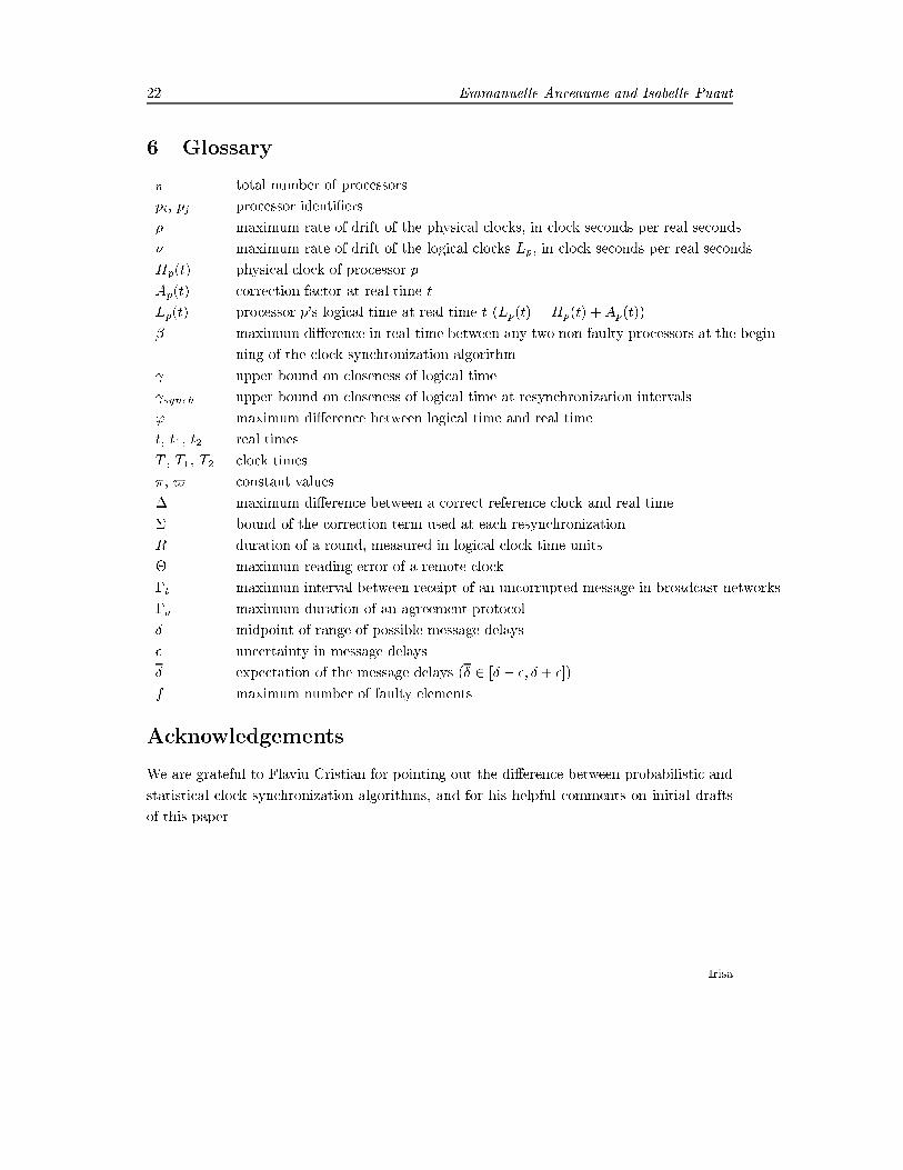
22 Emmanuelle Anceaume and Isabelle Puaut6 Glossaryn total number of processorspi, pj processor identi�ers� maximum rate of drift of the physical clocks, in clock seconds per real seconds� maximum rate of drift of the logical clocks Lp, in clock seconds per real secondsHp(t) physical clock of processor pAp(t) correction factor at real time tLp(t) processor p's logical time at real time t (Lp(t) = Hp(t) +Ap(t))� maximum di�erence in real-time between any two non faulty processors at the begin-ning of the clock synchronization algorithm upper bound on closeness of logical time synch upper bound on closeness of logical time at resynchronization intervals' maximum di�erence between logical time and real timet, t1, t2 real timesT , T1, T2 clock times�, $ constant values� maximum di�erence between a correct reference clock and real time� bound of the correction term used at each resynchronizationR duration of a round, measured in logical clock time units� maximum reading error of a remote clock�t maximum interval between receipt of an uncorrupted message in broadcast networks�a maximum duration of an agreement protocol� midpoint of range of possible message delays� uncertainty in message delays� expectation of the message delays (� 2 [� � �; � + �])f maximum number of faulty elementsAcknowledgementsWe are grateful to Flaviu Cristian for pointing out the di�erence between probabilistic andstatistical clock synchronization algorithms, and for his helpful comments on initial draftsof this paper.Irisa

A Taxonomy of Clock Synchronization Algorithms 23References[Arv94] K. Arvind. Probabilistic clock synchronization in distributed systems. IEEETransactions on Parallel and Distributed Systems, 5(5):474{487, May 1994.[CAS86] F. Cristian, H. Aghili, and R. Strong. Clock synchronization in the presence ofomission and performance failures, and processor joins. In Proc. of 16th Inter-national Symposium on Fault-Tolerant Computing Systems, July 1986.[CASD85] F. Cristian, H. Aghili, R. Strong, and D. Dolev. Atomic broadcsat: from simplemessage di�usion to byzantine agreement. In Proc. of 15th International Sym-posium on Fault-Tolerant Computing Systems, 1985.[Cri89] F. Cristian. Probabilistic clock synchronization. In Distributed Computing, vo-lume 3, pages 146{158. Springer Verlag, 1989.[DHSS95] D. Dolev, J. Y. Halpern, B. Simons, and R. Strong. Dynamic fault-tolerant clocksynchronization. Journal of the ACM, 42(1):143{185, January 1995.[FC95a] C. Fetzer and F. Cristian. Lower bounds for function based clock synchroni-zation. In Proc. of 14th International Symposium on Principles of DistributedComputing, August 1995.[FC95b] C. Fetzer and F. Cristian. An optimal internal clock synchronization algorithm.In Proc. of the 10th Annual IEEE Conference on Computer Assurance, June1995.[FC97] C. Fetzer and F. Cristian. Integrating external and internal clock synchronization.Journal of Real-Time Systems, 12(2):123{172, 1997.[GZ86] R. Gusella and S. Zatti. An election algorithm for a distributed clock synchroniza-tion program. In Proc. of 6th International Conference on Distributed ComputingSystems, pages 364{373, 1986.[GZ89] R. Gusella and S. Zatti. The accuracy of the clock synchronization achieved byTEMPO in berkeley UNIX 4.3BSD. IEEE Transactions on Software Engineering,15(7):847{853, July 1989.[HSSD84] J. Halpern, H. Strong, B. Simons, and D. Dolev. Fault-tolerant clock synchro-nization. In Proc. of 3rd International Symposium on Principles of DistributedComputing, pages 89{102, 1984.PI n�1103

24 Emmanuelle Anceaume and Isabelle Puaut[KO87] H. Kopetz and W. Ochsenreiter. Clock synchronization in distributed real-timecomputer systems. IEEE Transactions on Computers, C-36(8):933{940, August1987.[Lam78] L. Lamport. Time, clocks and the ordering of events in a distributed system.Communications of the ACM, 21(7):558{565, July 1978.[LL84] J. Lundelius and N. Lynch. An upper and lower bound for clock synchronization.Information and Control, 62(2/3):190{204, August 1984.[LL88] J. Lundelius and N. Lynch. A new fault-tolerant algorithm for clock synchroni-zation. Information and Computation, 77:1{36, 1988.[LMS85] L. Lamport and P. M. Melliar-Smith. Synchronizing clocks in the presence offaults. Journal of the ACM, 32(1):52{78, July 1985.[LSP82] L. Lamport, R. Shostak, and M. Pease. The byzantine generals problem. acmtpls,4:383{401, 1982.[Mar83] K. Marzullo. Loosely-coupled distributed services: a distributed time service. PhDthesis, Standford University, Computer Systems Laboratory, 1983.[MO83] K. Marzullo and S. Owicki. Maintaining the time in a distributed system. InProc. of 2nd International Symposium on Principles of Distributed Computing,pages 295{305, 1983.[MS85] S. Mahaney and F. Schneider. Inexact agreement: Accuracy, precision and gra-ceful degradation. In Proc. of 4th International Symposium on Principles ofDistributed Computing, pages 237{249, August 1985.[OS94] A. Olson and K. Shin. Fault-tolerant clock synchronization in large multicom-puter systems. IEEE Transactions on Parallel and Distributed Systems, 5, 1994.[PB95] M. P uegl and D. Blough. A new and improved algorithm for fault-tolerant clocksynchronization. Journal of Parallel and Distributed Computing, 27:1{14, 1995.[RSB90] P. Ramanathan, K. Shin, and R. Butler. Fault-tolerant clock synchronization indistributed systems. IEEE Computer, 23(10):33{44, October 1990.[SC90] F. Schmuck and F. Cristian. Continuous clock amortization need not a�ect theprecision of a clock synchronization algorithm. In Proc. of 9th InternationalSymposium on Principles of Distributed Computing, pages 133{144, 1990. Irisa
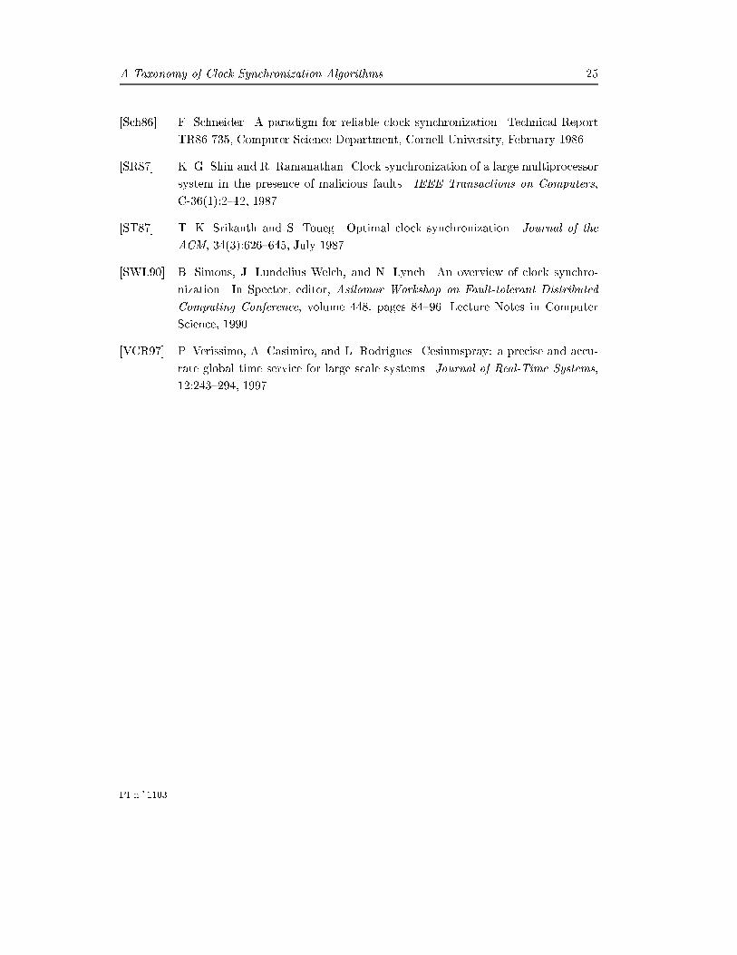
A Taxonomy of Clock Synchronization Algorithms 25[Sch86] F. Schneider. A paradigm for reliable clock synchronization. Technical ReportTR86-735, Computer Science Department, Cornell University, February 1986.[SR87] K. G. Shin and R. Ramanathan. Clock synchronization of a large multiprocessorsystem in the presence of malicious faults. IEEE Transactions on Computers,C-36(1):2{12, 1987.[ST87] T. K. Srikanth and S. Toueg. Optimal clock synchronization. Journal of theACM, 34(3):626{645, July 1987.[SWL90] B. Simons, J. Lundelius Welch, and N. Lynch. An overview of clock synchro-nization. In Spector, editor, Asilomar Workshop on Fault-tolerant DistributedComputing Conference, volume 448, pages 84{96. Lecture Notes in ComputerScience, 1990.[VCR97] P. Verissimo, A. Casimiro, and L. Rodrigues. Cesiumspray: a precise and accu-rate global time service for large scale systems. Journal of Real-Time Systems,12:243{294, 1997.
PI n�1103