a technicians approach to cable testing …...n ge jbc phase directional overcurrent relay • uses...
TRANSCRIPT
1
CABLE TESTING STANDARDS: O V E R V I E W O F T H E
A Technicians Approach to Directional Overcurrent Relaying Understanding and Testing Directional Relays

2
Moderator
n Ron Spataro AVO Training Institute Marketing Manager

3
Q&A
n Send us your questions and comments during the presentation
4
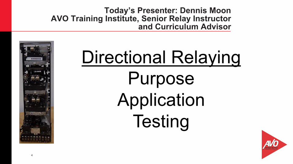
Today’s Presenter: Dennis Moon AVO Training Institute, Senior Relay Instructor
and Curriculum Advisor
Directional Relaying Purpose
Application Testing
5
• IEEE number is 67 with designators of P, N, G, Q
• Requires two quantities:
1. Polarizing quantity
• May be polarizing Voltage (Vpol)
• May be polarizing Current (Ipol)
• May be both Vpol and Ipol
2. Operating current: Designated as Iop (Ifault)
• Requires a phase angle displacement between polarizing and operating quantity (MTA)
Directional Relaying Concepts
6
Directional Relaying Principles
• Fault current direction may be in the same direction as load or in the opposite direction of load.
• Even if the directional unit contact is closed or the directional logic is correct, the fault current must still exceed the overcurrent setting for the relay to trip.
• Mechanical and solid state relays determine direction by connection.
• Numerical relays determine direction by logic. (Forward, Reverse)
• Directional relays may or may not make use of directionally controlled instantaneous units.
• Directional Unit operating area is 180 degrees. 90 degrees on each side of the MTA
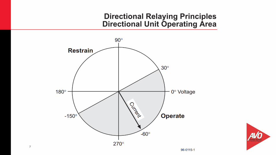
7
Directional Relaying Principles Directional Unit Operating Area

8
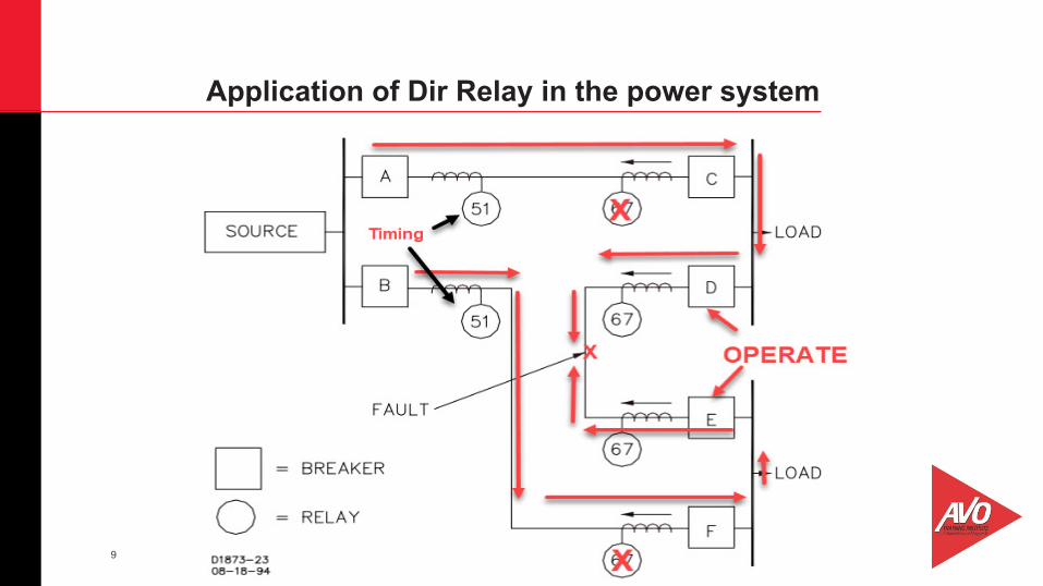
1. Determine direction of fault current flow 2. Protect the system from damaging fault
current 3. Trip for bus faults but maintain loads 4. Allow for relay co-ordination between
substations 5. Overcurrent settings and time delay can be
reduced
Purpose of Dir Relay in the power system
9
Application of Dir Relay in the power system

10
Application of Dir Relay in the power system
11
Phase Directional Relaying Quadrature Polarizing
Phase relays use quadrature polarizing Voltage This means that the polarizing voltage for a fault involving “A” phase current is voltage BC. B phase current is polarized by voltage CA, and C phase current is polarized by voltage AB. The term “quadrature” is defined as one quarter or one fourth. In our case the quadrature voltage position on a vector wheel is one forth of 360 degrees.

12
Quadrature Polarizing Quantities
13
Dir Unit Minimum Pickup (Sensitivity)
n The directional unit must be very sensitive. n Voltage Polarized Directional Unit pickup is calibrated in VA.
n Vpol Directional unit pickups range from .75VA to 13.6VA
n Ipol Directional Unit pickup is .5 amps (Mechanical Relays) n The minimum pickup is always at the MTA
14
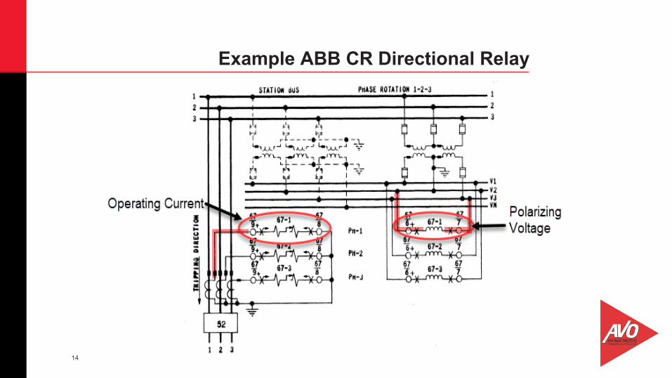
Example ABB CR Directional Relay

15
CR Directional Relay MTA

16
CR Directional Relay Connections
17
Examples of other phase directional relays
n GE JBC Phase Directional Overcurrent Relay • Uses quadrature polarizing voltage • Has an MTA of 45 degrees • Has a pickup of 2VA at MTA • Has a directionally controlled instantaneous unit

18
Examples of other phase directional relays
n Basler 67 directional relay • Uses quadrature polarizing voltage • Has a pickup of .75 VA at MTA • Has a variable MTA options
– Continuously adjustable from 0 – 90 degrees – Switch selectable at 30, 45, 60, and 75 degrees
• Has either directional or non directional instantaneous element options
19
Principles of Ground Directional Relaying
n Uses both voltage and current polarizing quantities • Polarizing voltage comes from broken delta PT’s or calculated 0
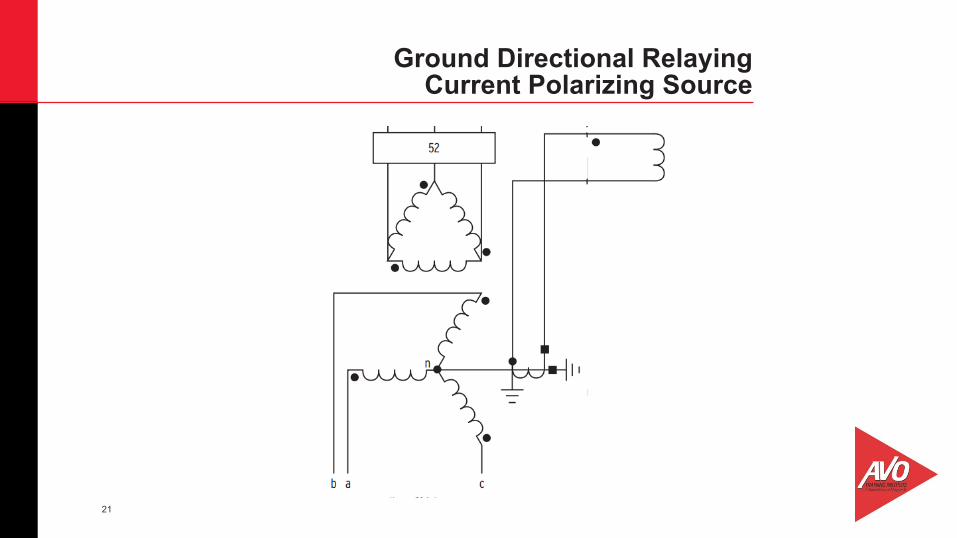
sequence voltage (numerical relays) • Polarizing current comes from transformer neutral CT or current
balance CT. • Operating current is the residual current from the phase CT
connections.

20
Broken Delta PT Connection for voltage polarizing source
21
Ground Directional Relaying Current Polarizing Source
22
GroundDirectional Relaying MTA Considerations
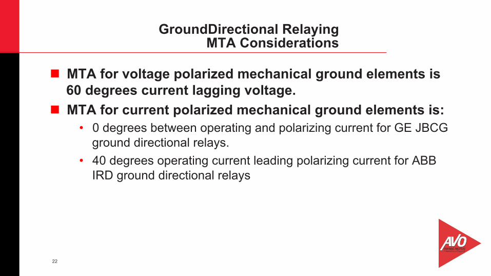
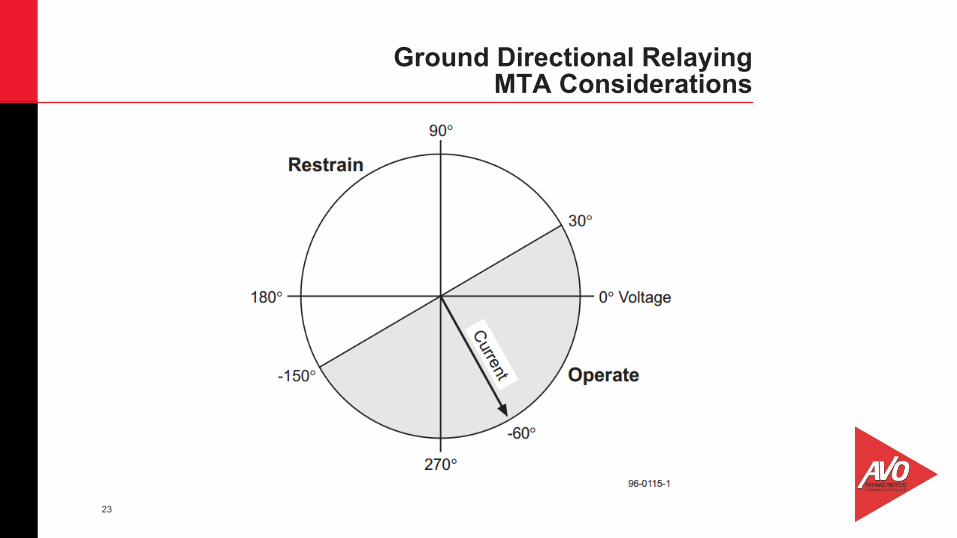
n MTA for voltage polarized mechanical ground elements is 60 degrees current lagging voltage.
n MTA for current polarized mechanical ground elements is: • 0 degrees between operating and polarizing current for GE JBCG
ground directional relays. • 40 degrees operating current leading polarizing current for ABB
IRD ground directional relays
23
Ground Directional Relaying MTA Considerations

24
Ground Directional Relaying Pickup Values
n Minimum pickup for mechanical directional relays depends on manufacturer:
• ABB IRD – For voltage polarized directional element the pickup is either
2 or 4 VA at MTA depending on induction disk tap range. – For current polarized directional element the pickup is
either .5 or 1 amp at MTA depending on induction disk tap range.
– If Ipol directional unit is tested with current in series through operate and directional unit then pickup is either . 57 or 1.3 amps depending on induction disk tap range.

25
Ground Directional Relaying Pickup Values
n Minimum pickup for mechanical directional relays depends on manufacturer:
• GE JBCG – When voltage polarized, minimum pickup at MTA is setable
from 3.6 to 14.4 VA – When current polarized, minimum pickup at MTA is setable
from .25 to 1 amp. n If the voltage polarized pickup is set to a specific value, the
current polarized pickup cannot also be set to a specific value since there is only one dir unit spring adjustment for both Ipol and Vpol.
26
Ground Directional Relaying Directionally Controlled Inst Unit
n On both the ABB IRD, and the GE JBCG, the instantaneous units are directionally controlled and are tapped for selectable pickup values.
n The ABB IRD relay has separate voltage and current directional elements.
n The GE JBCG has a single 8 pole directional unit which does both voltage and current polarizing operations.
27
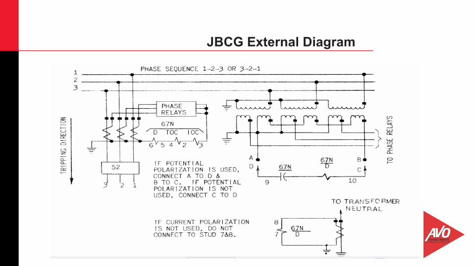
JBCG External Diagram

28
IRD External Diagram

29
Directional Relaying Principles SEL Relays
n SEL Microprocessor Based Distribution relays (SEL-351, 751) follow essentially the same directional relay concepts and principles with a few added twists and turns.
n Because the relay contains all directional elements (both phase and ground), the application of the proper voltages, currents and phase angles can be challenging.
n Due to time constraints we will discuss Positive and Negative sequence voltage polarization for phase relays, and Zero sequence voltage and neutral current polarization for ground relays.

30
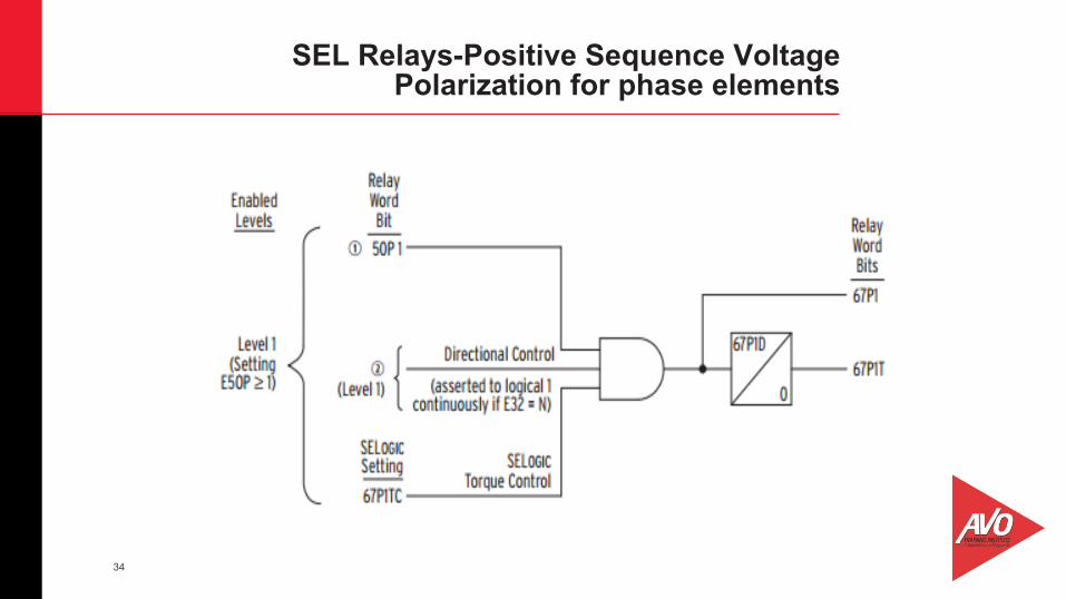
SEL Relays-Positive Sequence Voltage Polarization for phase elements
n Positive Sequence voltage polarization requires the following:
1. Direction must be selected as either forward or reverse. 2. MTA is determined by Z1Ang 3. Three phase positive sequence voltage must be present. 4. Three phase positive sequence current above setting must be
present. (The relay will not respond directionally to single phase or phase to phase current. It MUST be three phase balanced current.
5. The current will lag the voltage by the Z1Ang setting.

31
SEL Relays-Positive Sequence Voltage Polarization for phase elements
n Minimum Directional Element Settings for basic testing • E32 = Auto • ELOP = N • Dir1 = F • Order = Q • 50P32P = 1
n With E32 set to auto, all other setting will automatically be set by the relay.

32
SEL Relays-Positive Sequence Voltage Polarization for phase elements
MTA determined by Z1Ang

33
SEL Relays-Positive Sequence Voltage Polarization for phase elements
34
SEL Relays-Positive Sequence Voltage Polarization for phase elements
35
SEL Relays-Negative Sequence Voltage Polarization for phase elements
n Any time the fault is an unbalanced fault, (and most are), negative sequence voltage appears on the system and can be use for voltage polarization. The following applies to negative sequence voltage polarization:
1. The positive sequence “rotation” must be designated in the setting “PHROT” as either ABC or ACB
2. The negative sequence will be opposite “PHROT”. 3. The relay must see negative sequence voltage for phase,
phase to phase, and 3 phase unbalanced faults.

36
SEL Relays-Negative Sequence Voltage Polarization for phase elements
MTA determined by Z1Ang
37
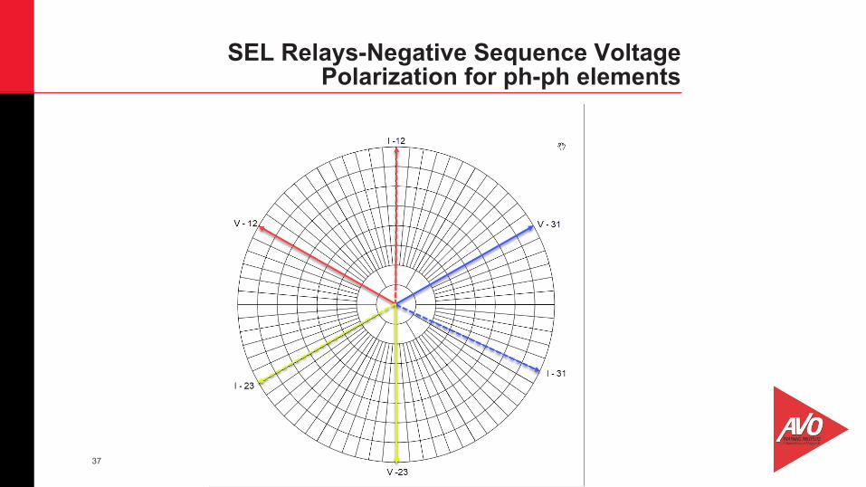
SEL Relays-Negative Sequence Voltage Polarization for ph-ph elements

38
SEL Relays-Negative Sequence Voltage Polarization for Ph-Ph TOC elements
39
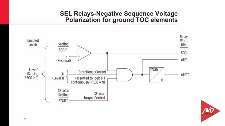
SEL Relays-Negative Sequence Voltage Polarization for ground TOC elements

40
SEL Relays-Negative Sequence Voltage Polarization for ground elements
Order = Q
Uses Z1ANG as MTA

41
Zero Sequence Voltage Polarization
Order = V
Uses Z0Ang as MTA
42
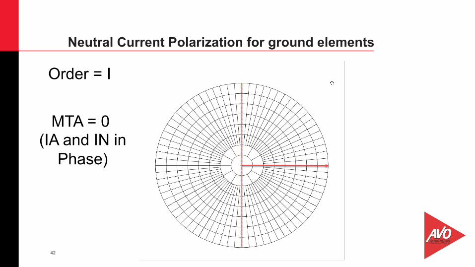
Neutral Current Polarization for ground elements
Order = I
MTA = 0 (IA and IN in
Phase)

43
Ø Directional Units have a 180 degree operating area. 90 degrees on each side of the MTA.
Ø The direction of current flow is determined by comparing the current flow to a polarizing voltage or current.
Ø Directional unit must be sensitive. This means the pickup of the directional unit is very low and calibrated in VA.
Ø Phase directional relays use quadrature polarizing voltage. Ø Ground directional relays use broken delta polarizing voltage or transformer
neutral current for current polarization. Ø Microprocessor relays use positive, negative, and zero sequence voltages for
polarizing quantities. They also use transformer neutral current for current polarizing functions.
Summary

44
15% Off Hands-On Courses Below When enrolling use promo code: RELAY18
n Protective Relay Maintenance, Basic • Certification Course
n Protective Relay Maintenance, Advanced • Certification Course
n Protective Relay Maintenance, Solid-State • Certification Course
n Protective Relay Maintenance, Generation • Certification Course
n Microprocessor- Based Relay Testing, Distribution/Feeder
n Microprocessor- Based Relay Testing, Generation
n Advanced Visual Testing Software
*This offer can only be applied to courses registered after April 17, 2018 and attended on or before November 30, 2018. This offer cannot be used towards courses already purchased or added to any other existing discounts.
45
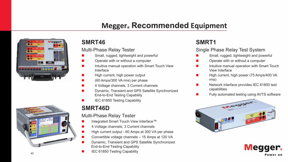
Megger®RecommendedEquipment
SMRT46D Multi-Phase Relay Testern Integrated Smart Touch View Interface™ n 4 Voltage channels, 3 Current channels n High current output - 60 Amps at 300 VA per phase n Convertible voltage channels – 15 Amps at 120 VA n Dynamic, Transient and GPS Satellite Synchronized
End-to-End Testing Capability n IEC 61850 Testing Capability
SMRT1 Single Phase Relay Test System n Small, rugged, lightweight and powerful n Operate with or without a computer n Intuitive manual operation with Smart Touch
View Interface n High current, high power (75 Amps/400 VA
rms) n Network interface provides IEC 61850 test
capabilities n Fully automated testing using AVTS software
SMRT46 Multi-Phase Relay Tester n Small, rugged, lightweight and powerful n Operate with or without a computer n Intuitive manual operation with Smart Touch View
Interface n High current, high power output n (60 Amps/300 VA rms) per phase n 4 Voltage channels, 3 Current channels n Dynamic, Transient and GPS Satellite Synchronized
End-to-End Testing Capability n IEC 61850 Testing Capability

46
Join Us For Our Next Webinar
Titled: “An Introduction to Power Quality” Presented by: Andy Sagl - Megger® Product Manager
Tuesday, May 22, 2018 at 1 PM CST
Register here: https://attendee.gotowebinar.com/register/5671396814129244930

47
Questions? After more than 50 years, AVO Training remains a global leader in safety and maintenance training for the electrical industry. We deliver an engaging, hands-on experience for our clients in a professional, real-world environment. We strive to provide industry relevant courses in a practical and flexible learning environment through an ongoing commitment to quality service, integrity, instruction, and client satisfaction. Our goal is to convey practical job skills and career development for our clients and students by saving lives through a world-class learning experience.