a test method for assessing the performance of oil mist ... · a test method for assessing the...
TRANSCRIPT

Prepared by the Health and Safety Laboratory for the Health and Safety Executive 2015
Health and Safety Executive
A test method for assessing the performance of oil mist detectors
RR1059Research Report


Andrew ThorpeHealth and Safety LaboratoryHarpur HillBuxtonDerbyshire SK17 9JN
Ignition of flammable mists, particularly oil mist, which can occur in offshore locations such as gas turbine enclosures, diesel/ships engine rooms and platform legs present a significant major accident hazard potential. Oil mist detection with appropriate emergency response (OMDs) is identified as a significant risk mitigation. However, there are gaps in the knowledge as to how effectively, locate, maintain and operate OMDs in different environments. This work aims to produce a test method capable of assessing the effectiveness of oil mist detection under conditions typical of those found in practice to enable these gaps to be addressed.
A method for testing OMDs has been produced based on methods previously developed at HSL and a recent international standard. The use of isokinetic gravimetric samplers is recommended to measure absolute airborne spray/mist concentration with which to compare OMD response. It is a fundamental method and not affected by changes in the physical properties of the droplets, taking around 1–10 minutes to carry out the measurement.
The test method will allow the performance of all types of OMD to be fully characterised as a function of mist concentration, mist droplet size, mist composition, and air velocity. It will also allow the effects of interfering aerosols such as dust and water droplets to be investigated. The effect of detector ageing on detection efficacy can also be established.
This report and the work it describes were funded by the Health and Safety Executive (HSE). Its contents, including any opinions and/or conclusions expressed, are those of the authors alone and do not necessarily reflect HSE policy.
A test method for assessing the performance of oil mist detectors
HSE Books
Health and Safety Executive

© Crown copyright 2015
First published 2015
You may reuse this information (not including logos) free of charge in any format or medium, under the terms of the Open Government Licence. To view the licence visit www.nationalarchives.gov.uk/doc/open-government-licence/, write to the Information Policy Team, The National Archives, Kew, London TW9 4DU, or email [email protected].
Some images and illustrations may not be owned by the Crown so cannot be reproduced without permission of the copyright owner. Enquiries should be sent to [email protected].
Acknowledgements
The author would like to thank Richard Bettis (HSL) for his input in designing the test protocol.
ii

iii
KEY MESSAGES
There have been numerous occasions where significant fires have occurred inside UK
offshore gas turbine enclosures. In many cases this was because oil mist leaks were not
detected by the installed oil mist detector (OMD) instruments.
It is generally recognised that the detection characteristics of OMDs are not presently
fully understood, and it is expected that the physical properties of airborne droplets will
affect their response.
Methods of spray generation for use in a test method have been reviewed. It was
concluded that medical nebulisers, rotary atomisers and smoke generators would
generate a range of droplet sizes suitable for assessing the performance of OMDs.
Methods of spray measurement for use in a test method have been reviewed. It was
concluded that a laser diffraction instrument would be suitable for characterising the
size distribution of airborne spray droplets in real time
A test method for assessing the performance of commercially available oil mist
detectors has been devised. It is based on methods previously developed at HSL and
current standard test methods. It incorporates the spray generation and spray
measurement techniques methods described in the previous bullet points.
The proposed test method addresses the limitations of previous and current OMD test
methods. It is designed so that OMD response can be investigated in moving air as a
function of spray droplet size and spray composition. It can also be used to investigate
the effects of interfering aerosols such as dust and water mist/spray.
iv
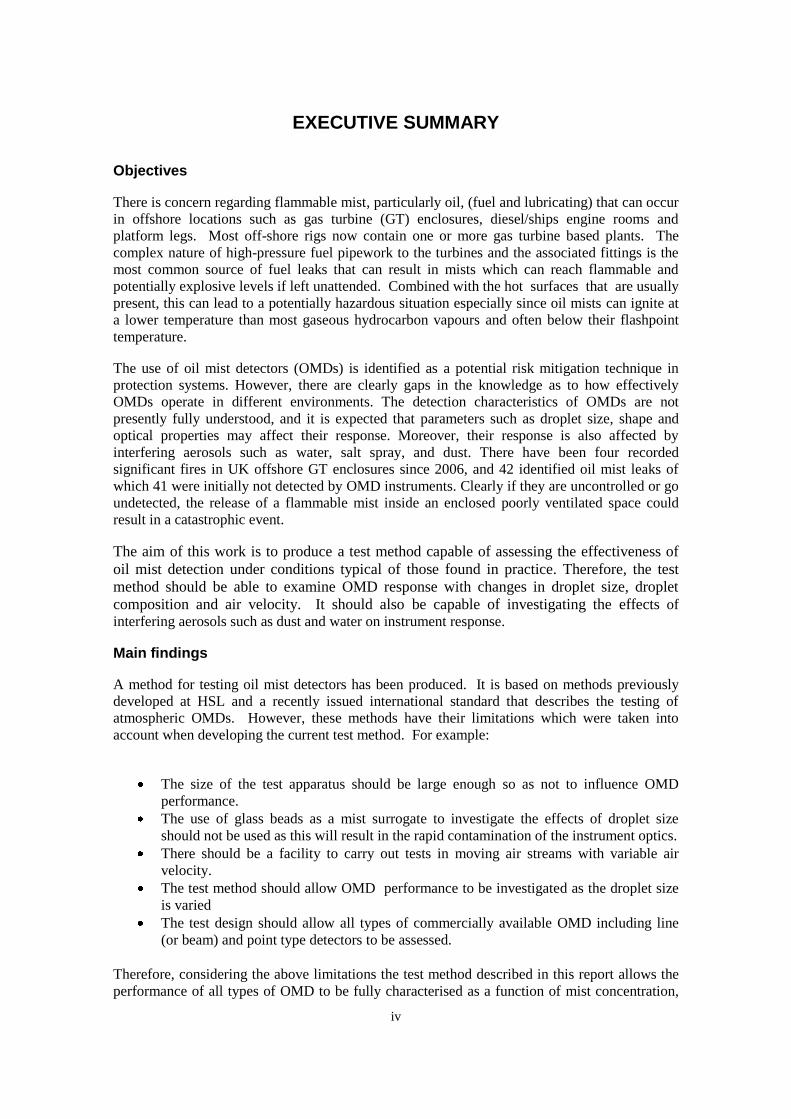
EXECUTIVE SUMMARY
Objectives
There is concern regarding flammable mist, particularly oil, (fuel and lubricating) that can occur
in offshore locations such as gas turbine (GT) enclosures, diesel/ships engine rooms and
platform legs. Most off-shore rigs now contain one or more gas turbine based plants. The
complex nature of high-pressure fuel pipework to the turbines and the associated fittings is the
most common source of fuel leaks that can result in mists which can reach flammable and
potentially explosive levels if left unattended. Combined with the hot surfaces that are usually
present, this can lead to a potentially hazardous situation especially since oil mists can ignite at
a lower temperature than most gaseous hydrocarbon vapours and often below their flashpoint
temperature.
The use of oil mist detectors (OMDs) is identified as a potential risk mitigation technique in
protection systems. However, there are clearly gaps in the knowledge as to how effectively
OMDs operate in different environments. The detection characteristics of OMDs are not
presently fully understood, and it is expected that parameters such as droplet size, shape and
optical properties may affect their response. Moreover, their response is also affected by
interfering aerosols such as water, salt spray, and dust. There have been four recorded
significant fires in UK offshore GT enclosures since 2006, and 42 identified oil mist leaks of
which 41 were initially not detected by OMD instruments. Clearly if they are uncontrolled or go
undetected, the release of a flammable mist inside an enclosed poorly ventilated space could
result in a catastrophic event.
The aim of this work is to produce a test method capable of assessing the effectiveness of
oil mist detection under conditions typical of those found in practice. Therefore, the test
method should be able to examine OMD response with changes in droplet size, droplet
composition and air velocity. It should also be capable of investigating the effects of
interfering aerosols such as dust and water on instrument response.
Main findings
A method for testing oil mist detectors has been produced. It is based on methods previously
developed at HSL and a recently issued international standard that describes the testing of
atmospheric OMDs. However, these methods have their limitations which were taken into
account when developing the current test method. For example:
The size of the test apparatus should be large enough so as not to influence OMD
performance.
The use of glass beads as a mist surrogate to investigate the effects of droplet size
should not be used as this will result in the rapid contamination of the instrument optics.
There should be a facility to carry out tests in moving air streams with variable air
velocity.
The test method should allow OMD performance to be investigated as the droplet size
is varied
The test design should allow all types of commercially available OMD including line
(or beam) and point type detectors to be assessed.
Therefore, considering the above limitations the test method described in this report allows the
performance of all types of OMD to be fully characterised as a function of mist concentration,

v
mist droplet size, mist composition, and air velocity. It also allows the effects of interfering
aerosols such as dust and water droplets to be investigated.
The use of isokinetic gravimetric samplers is recommended to measure absolute airborne
spray/mist concentration with which to compare OMD response. It is a fundamental method
and not affected by changes in the physical properties of the droplets. At the mist
concentrations anticipated for OMD testing (0.5 – 5 % of the LEL i.e. 250 to 2500 mg m-3
) it
would only take around 1 – 10 minutes to carry out a gravimetric measurement.
Different methods of spray generation have been discussed. The recommended methods for
carrying out OMD assessment are medical nebulisers, rotary atomisers and smoke generators
since they can generate a wide range of droplet sizes in sufficiently large quantities.
The use of an on-line method for measuring the size distribution of the airborne spray/mist is
recommended since this will rapidly show the effects of changing the generation method and
operating parameters on droplet size. HSL currently owns a laser diffraction instrument
(Malvern 2600 HSD Particle Size Analyser) capable of measuring droplets from 2 – 800 µm
diameter, although this is some years old and may need upgrading or replacing for the current
work. Malvern Instruments Ltd currently sells or will hire out their “Spraytech” spray analyser.
The proposed test method is regarded as suitable for the assessment of the types of OMD that
are currently available on the market.

CONTENTS PAGE
1. INTRODUCTION .................................................................... 1
2. IMPLICATIONS ...................................................................... 3
3. METHODOLOGY ................................................................... 4
3.1 Summary of existing OMD test methods 4 3.2 limitations OF EXISTING OMD TEST METHODS 7 3.3 SPray/mist generation 7 3.4 Measurement of droplet size 10 3.5 a proposed new experimental test method 13
4. CONCLUSIONS ................................................................... 19
5. REFERENCES ..................................................................... 20

1
1. INTRODUCTION
There are numerous situations that can lead to the generation of a flammable mist which may,
under certain conditions of use result in a significant fire and explosion hazard. Early detection
of such emissions is important since it can significantly reduce the likelihood of a hazardous
situation arising or mitigate its effect.
A flammable mist is usually produced by two mechanisms: a) the pressurised escape of a liquid,
for example from a hole or split in a hose of a hydraulic system or b) where oil is vaporised by
contact with a hot surface and then forms small droplets as it condenses in the cooler
surrounding air. It will ignite at a lower temperature than most gaseous hydrocarbon vapours
and once ignited, the combustion can be very destructive.
Of particular concern to HSE are the flammable mists, particularly oil (fuel and lubricating),
that can occur in various offshore locations such as gas turbine (GT) enclosures, diesel/ships
engine rooms and platform legs. Most off-shore rigs now contain one or more gas turbine based
plants. The complex nature of high-pressure fuel pipework to the turbines and the associated
fittings is the most common source of fuel leaks that can result in mists, which can reach
flammable and potentially explosive levels if left unattended.
HSE recognises the use of oil mist detectors (OMDs) as a potential risk mitigation technique in
safety systems (HSE, 2003). However, it is also recognised that current oil mist detection
systems may not give reliable measurements and/or detection. Influencing factors such as oil
type, droplet size, air flow, humid and dusty environments and location of the instrument can
significantly affect the accuracy and reliability of measurements. This appears to be
corroborated by the occurrence of four significant fires offshore in the UK in GT enclosures
since 2006 and 42 identified oil mist leaks, of which 41 were initially not detected by installed
instruments (Santon, 2005). It is clear, then, that the effects of influencing factors on OMD
performance need to be investigated and better defined.
The aim of this work is to produce a test method capable of assessing the effectiveness of oil
mist detection under conditions typical of those found in practice. The test method should at
least be able to:
Generate a range of droplet sizes representative of those produced in a real workplace
situation. These are likely to range from a few microns, where aerosols are produced
from condensation of hot gases, up to tens or hundreds of microns, where sprays or
mists are produced by leaks of flammable liquids from holes or defects in pressurised
systems. Most of the existing test methods (BS ISO 16437 [2012], IACS [2005], IMO
[2003]) challenge the OMDs with aerosols consisting of droplets less than 10 µm in
diameter.
Investigate the response of OMDs to mists produced from different flammable liquids.
Investigate the response of OMDs to changes in the surrounding air velocity. In
practice, oil mist detectors are often deliberately placed in locations where there is a
moving air stream, e.g. in the exhaust of gas turbine enclosures. Many of the existing
test methods are carried out in low air movements or “still air” and therefore the OMDs
are not tested in “real” conditions.

2
Investigate how interfering aerosols such as water sprays, dust (e.g. salt mists) affect
OMD response.

3
2. IMPLICATIONS
The test equipment described in this report will be designed and constructed as part of the next
phase of the project. Oil mist detectors of various types will be obtained (e.g. purchased, loaned)
from manufacturers for the tests.

4
3. METHODOLOGY
Various methods for testing the performance of oil mist detectors already exist or have been
proposed. These have been discussed previously by Thorpe (2013) and are summarised below.
3.1 SUMMARY OF EXISTING OMD TEST METHODS
3.1.1 Bettis (2001)
Bettis (2001) describes a test method for assessing the performance of OMDs under changing
conditions such as mist concentration, mist composition, air velocity and droplet diameter. He
compares the OMD measurements with those obtained using standard isokinetic gravimetric
sampling methods. He uses a variety of spray/mist generating techniques to generate droplets in
the 1 – 50 µm size range. The tests include:
Assessment of OMD response to varying diesel oil concentration by using single and
multiple arrays of medical nebulisers. Droplet concentration was varied by changing the
flow of air through the test rig.
Assessment of OMD response to different fluids such as polyol ester hydraulic fluid, a
light mineral oil, diesel fuel and water by generating the droplets using an air-blast
spray gun.
Investigation of the effect of changing air velocity on OMD response.
Assessment of OMD response to changing droplet size by using different sizes of glass
beads as a surrogate test material.
3.1.2 Bettis (2002)
As a result of the previous work and a subsequent review of oil mist detection, Bettis (2002)
proposed a possible OMD test protocol. The key points are summarised as follows:
Reference method: A pre-calibrated reference real-time instrument is used instead of
an isokinetic gravimetric sampler to determine the response of the other on-line
instruments under test.
Test chamber: A 1 m3 chamber is used to carry out tests on the effects of oil mist
concentration, oil type and droplet size on OMD performance. The dimensions are such
that “line”, i.e. open-path or beam, instruments can be tested through windows in either
side.
Effects of concentration: The response of the instrument under test is compared to the
reference instrument, which is placed in close proximity, for a number of concentrations
to give a “response curve”.
Response to droplet size: Tests using two sizes of oil mist are recommended: a) an
aerosol containing small droplets using a smoke machine b) a mist of droplets produced
using an atomising spray system that will have a droplet size 1 to 2 orders of magnitude
larger. The output from the reference instrument is compared to that of the test
instrument over a range of concentrations.
Response to different materials: Nebulisers are suggested for aerosol generation since
they can operate with a wide range of materials. Various lubricating oils and water are
suggested as test materials. The output from the reference instrument is compared to
that of the test instrument over a range of concentrations for each material.
Response to ventilation rate (air velocity): It is proposed that tests are carried out
inside a duct through which air is pulled using a variable speed centrifugal fan,

5
producing air velocities of up to 10 m s-1
. Line (beam) detectors are placed to operate
across the diameter of the duct. Oil mist is introduced into the duct upstream of the fan
and testing is proposed at three air velocities (2, 4, and 8 m s-1
). The instrument under
test is compared to the reference instrument over a range of concentrations to indicate
any effect of air velocity.
3.1.3 Type testing procedure for crankcase oil mist detection/monitoring and alarm
The International Association of Classification Societies (IACS, 2005), which contributes
towards maritime safety and regulation, has developed a type test procedure to assess OMDs
fitted to engine crankcases that are used to prevent fires and mechanical breakdown. Although
this procedure is not specifically written for the types of instrument used in atmospheric oil mist
detection, most of the general test methods are applicable. Indeed, the test procedure described
in BS ISO 16437 (BSI, 2012) is based on this procedure, and has been modified or expanded for
use with atmospheric OMDs.
Specific test procedures taken from the document that are considered relevant to the
performance testing of atmospheric OMDs are:
Oil mist should be generated with suitable equipment using an SAE 80 monograde
mineral oil or equivalent and supplied to a test chamber having a volume of not less
than 1 m3. The oil mist produced should have a maximum droplet size of 5 μm.
All OMD tests should be carried out with an oil mist concentration in air, known in
terms of mg l-1
to an accuracy of ±10%.
The concentration of oil mist should be measured at the top and bottom of the test
chamber and should not differ by more than ±10%.
The oil mist monitoring arrangements should be capable of detecting oil mist in air
concentrations of between 0 and 10% of the lower explosive limit (LEL - approximately
50 mg l-1
).
The operation of the alarm indicators should be verified and should provide an alarm at
a maximum setting corresponding to 5% of the LEL.
Two OMDs requiring approval should be tested. One should be tested in the clean
condition and the other in a condition that represents the maximum degree of lens
obscuration that is stated as being acceptable by the manufacturer.
The measurement of reference oil mist concentration should be determined
gravimetrically or by an equivalent method.
The results of gravimetric analysis should be considered invalid and rejected if the
resultant calibration curve has an increasing gradient with respect to the oil mist
detection reading and if single results are more than 10% below the calibration curve.
The filters should be weighed to a precision of ±0.1 mg and the volume of air/oil mist
sampled to ±10 ml.
Where sensitivity levels can be adjusted, testing should be carried out at the extreme
and mid-point level settings.
Oil mist detection/monitoring devices should be tested in the orientation in which they
are intended to be installed.
Type testing should be carried out for each range of oil mist detection/monitoring
devices that a manufacturer requires classification approval.

6
3.1.4 BS ISO 16437 (2012) - Atmospheric oil mist detectors.
BS ISO 16437 (2012) is based on IMO (2003), "Code of Practice for Atmospheric Oil Mist
Detectors”. The actual test procedure is based on IACS (2005) – see 3.1.3.
It specifies requirements, test methods and performance criteria for OMDs installed on marine
vessels. However, since it is designed for assessing atmospheric OMDs, much of the content
applies to their use in other atmospheric environments such as gas turbine enclosures.
This standard specifies requirements for the following types of detectors:
Point type detectors employing a point aspirating sampling device or relying on
dispersion of oil mist.
Aspirating detectors, whereby the sampling point is separated from the sensing unit(s)
and uses a pipe network for carrying the sampling air to the sensing unit(s).
It should be used as guidance only for the testing of other types of detectors that work using
different detection principles.
The standard states that the OMD test method should determine a measure of the aerosol
concentration, which when passing through the detector, just causes an alarm to be raised. This
is achieved by introducing oil mist into a test chamber so that the detector is subjected to a
slowly increasing concentration, and recording the concentration at the moment when an alarm
is generated. The calibration procedure consists of firstly calibrating two master detectors using
a gravimetric reference method and then using these to measure the performance of the detector
under assessment. This is described in Annex A - “Calibration of master detector and/or
functional test for product detector and Annex B - “An example of alternative method for the
product detectors” of the standard. A typical measurement procedure would be:
Mount the OMD in a test chamber specified in Annex A or B of the standard in its
normal operating position, by its normal means of attachment
Prior to a test, purge the test chamber with clean air to ensure that the chamber and
OMD are free from oil mist.
Unless otherwise stated, maintain the air temperature at 23 ± 5 o C.
Allow the detector and monitoring equipment to stabilise for at least 15 minutes unless
specified by the manufacturer.
Perform an oil mist test as specified in Annex A or B of the standard using an oil mist
generator of the type specified in Annex C – “An example of an oil mist generator”.
Measure the reference concentration in the proximity of the detector
Record the oil mist alarm response value.
The standard describes a repeatability test to demonstrate that the OMD has stable behaviour
with respect to sensitivity. The alarm set point of the OMD is tested 6 times using the above
procedure. The maximum and minimum of these alarm set points are recorded and in order to
pass the repeatability test, the ratio of the maximum to minimum should not be greater than 1.6.
The standard also describes a test schedule to demonstrate the ability of the OMD to function
correctly with changing operational conditions such as temperature, humidity, vibration etc.

7
3.2 LIMITATIONS OF EXISTING OMD TEST METHODS
The test methods discussed previously have their limitations when used to investigate the
various factors that influence OMD performance. These will need to be considered when
designing a new test method for our requirements, and are summarised below:
The size of the test apparatus should be large enough as not to influence OMD
performance. For example, Bettis (2001) originally used a size of duct that was too
small to comfortably accommodate the OMD under test, which resulted in unexplained
effects caused by turbulent air flow patterns around the OMD. He also found that
mounting the OMD on the side of the duct could, at certain air velocities, cause the air
flow through the OMD to reverse thereby preventing it from sampling from the duct.
The use of glass beads as a mist surrogate by Bettis (2001) to investigate the effects of
droplet size resulted in rapid contamination of the instrument optics and was not
regarded as suitable.
IACS (2005) and BS ISO 16437 (2012) specify a cuboid test chamber with volumes of
not less than 1 m3 and 0.2 m
3 respectively with no facility to alter the air velocity
through them. Tests are therefore essentially carried out in still air conditions only.
IACS (2005) and BS ISO 16437 (2012) specify the generation of an aerosol of micron-
sized droplets by feeding oil (SAE 80 mono-grade mineral oil or equivalent) onto a
hotplate in a controlled manner. It specifies a maximum droplet size of 5 µm. Clearly,
this does not allow the effects of droplet size on OMD performance to be investigated.
In practice, droplets in the size range 1 to >100 µm may typically be produced and
ideally OMDs should be tested over a range of droplet sizes to which they are likely to
be exposed.
BS ISO 16437 (2012) is designed to test point type detectors. It does not specify the
testing of line (or beam) OMDs, although the test method could probably be adapted to
do so.
3.3 SPRAY/MIST GENERATION
3.3.1 General
Atomiser and spray generation technology is a vast subject area covering many different
applications such as: paint spraying, crop protection, perfume sprays, metered dose nebulisers
etc. It is beyond the scope of this project to describe in detail the theory of spray and mist
generation. The main aim is to choose methods of generation that produce droplets of the
required size and concentration suitable for assessing the performance of OMDs. Droplet size
may vary in diameter from several to hundreds of microns depending on the method of
generation.
The generation of mists is usually described as the condensation of high concentration vapour
clouds that occur during sudden expansion or cooling. Typical droplet diameters are a few
microns. The generation of sprays is described as the dispersion or ‘atomisation’ of liquids.
Droplet diameter can vary enormously depending on factors such as liquid pressure and the size
of hole that the liquid passes through.
The following are examples of the types of commercially available devices used to generate
liquid sprays or mists that might be considered for use in any proposed OMD test protocol.
8
3.3.2 Hydraulic spray generators
These force liquid under pressure through a nozzle, which then breaks up into droplets. The
degree of disintegration and hence droplet size depends mainly upon the physical properties
of the liquid and the conditions of ejection from the nozzle. The resultant size distribution
of droplets in a spray is very wide, but usually consists mostly of droplets with diameters
greater than 100 µm.
3.3.3 Air-blast spray generators
These use high velocity compressed air to aid the breakup of liquid emerging from a nozzle
under pressure, and generally achieve a finer degree of atomization typically resulting in
droplets less than 100 µm. They find use in conventional paint spray guns,
insecticide/disinfectant sprayers, and for therapeutic applications. They give a very wide range
of droplet sizes, though in some cases the range is reduced by trapping the larger droplets by
impaction within the atomizer. They are capable of generating high spray concentrations.
3.3.4 Atomisers/nebulisers
Atomisers or nebulisers are devices that use pressurised air only for converting a liquid into a
mist or fine spray. An example is the medical nebuliser, used to administer drugs in aerosol
form into the deeper regions of the respiratory system. Nebulisers tend to produce very small
droplets, and in low concentrations. Bettis (2001) used an array of medical nebulisers to
produce sufficient quantities of oil droplets in the size range 2 – 5 µm to assess OMD
performance
3.3.5 Rotating disc, cone or top spray generator
These utilise centrifugal forces to generate sprays from liquid fed into the device. The resultant
spray has a relatively uniform droplet size. They can be electrically driven, avoiding the need
for a compressed air supply and they are capable of generating large quantities of aerosol.
Droplet size can be varied by changing the speed of rotation or liquid feed rate. A rotary
atomiser is described in section 3.5.3.2
3.3.6 Electrostatic atomizers
Electrostatic atomization works by exposing a fluid to an intense electric field between the
charged atomizer and grounded work piece. The charge transfers to the fluid and repulsive
forces between the atomizer and the fluid tear the droplets from the atomizer and send them
toward the work surface. The droplet size produced with electrostatic atomization is a function
of three main factors:
Electric field strength
Liquid flow rate
Fluid properties (including its electrical properties)
The advantages of electrostatic spraying over conventional air atomisation are uniformity of
deposition, minimal wastage of liquid and greater control. Since the droplet cloud is charged
and attracted to the target, there is virtually no overspray.
It should be noted that there is a distinction between electrostatic atomization and electrostatic
spray charging. With electrostatic atomization, electrostatic forces are used to atomize the fluid.
9
In electrostatic spray charging, the spray is usually atomized by rotary means, and electrostatic
charge is applied to the droplets as they form to help attract them to the work surface.
An example of an electrostatic spray charging atomiser is the high-speed rotary bell atomizer
which is widely used in the painting industry for high quality applications.
3.3.7 Acoustic/ultrasonic atomizers
Ultrasonic nozzles use very high frequency vibration instead of high pressure or compressed air
to produce small and uniform droplets. The droplet size is determined by the vibration
frequency – a high frequency generates fine droplets and a low frequency generates coarse
droplets. Droplets sizes with a median diameter from a few microns to tens of microns can be
produced. They can also be used with air assistance to shape the spray pattern and adjust
droplet velocity without significantly changing droplet size.
Some applications of this technology include:
Medical nebulizers for inhalation therapy
Drying liquids; powdered milk for example, in the food industry
Surface coatings in the electronics industry
It should be noted that ultrasonic atomization technology is only effective for low viscosity
fluids and the spray concentration produced is generally quite low.
3.3.8 Monodisperse droplet generators
These tend to be used for research purposes and typical applications include filter testing and
aerosol sampler characterisation studies. Their major advantage is that they produce very well
defined aerosols of monodisperse droplets or particles (typically in the 1 to 10 µm range) and
are therefore ideal for investigating instrument/sampler performance as a function of particle
size. However, they are relatively expensive, can be difficult to set up and usually produce very
low concentrations of aerosol. Two examples are the spinning disc aerosol generator (sold by
BGI, Inc.) and the vibrating orifice aerosol generator (VOAG) sold by TSI, Inc.
3.3.9 Heated plate generator
This is the method described in IACS (2005) and BS ISO 16437 (2012) for generating the OMD
test aerosol. Oil mist is generated by heating an SAE 80 mono-grade mineral oil that is fed onto
a tray placed onto a hotplate. It is capable of generating large quantities of oil mist but there is
very little control over the droplet size and there are obvious fire hazards associated with
dropping flammable oil onto a hot surface. Droplet size is typically less than 5 µm.
3.3.10 Smoke machines
Smoke or fog machines that are often used in stage performances generate small size
condensation aerosols. A moderately high boiling point liquid such as polyethylene glycol or
light oil is vaporised and the vapour is then mixed with cooler air to produce a fine aerosol of
condensed liquid droplets. Such condensation aerosols have a small mean size (typically 1 to 5
µm). The biggest disadvantages of using these are that they will only operate with a limited
number of materials and there is very little control over the droplet size.

10
3.4 MEASUREMENT OF DROPLET SIZE
3.4.1 General
Various techniques exist for measuring the size distribution of airborne sprays and usually fit
into one of two categories - intrusive or non-intrusive. It is not the intention here to describe the
operating principles of each instrument in great detail but rather to give an idea of the various
types of instrument that are currently available for measuring the size of airborne droplets. The
decision on which instrument is most suitable will depend on several factors such as: particle
size range, particle velocity, particle concentration and cost. The following are examples of
instruments that are currently available for measuring the size (and in some cases the velocity)
of airborne droplets.
3.4.2 Real time - non-intrusive
3.4.2.1 General
The major advantages of this type of instrument are that it does not physically disturb the
aerosol being measured and will generally measure a wide range of droplet sizes. The main
disadvantage is that they are expensive (£50k - >£100k).
3.4.2.2 Laser Diffraction
Laser diffraction uses the principle of light scattering to measure the size distribution of airborne
droplets. The angular intensity of light scattered from a spray is measured as it passes through a
laser beam. The recorded scattering pattern is then analysed using an optical detector to
determine the droplet size distribution with a size range typically from 0.1 – 2000 µm. The size
distribution is determined almost instantaneously (usually within 100 µs) and the instrument is
therefore capable of measuring rapidly changing sprays. The Spraytech (Malvern Instruments
Ltd) is an example of this type of instrument, although HSL currently owns an older model (the
Malvern 2600 HSD Particle Size Analyser) which may be serviceable.
3.4.2.3 Phase Doppler Anemometry (PDA)
The PDA is used to measure the size, velocity and concentration of spherical particles, droplets
or bubbles suspended in gaseous or liquid flows. The most common application is the analysis
of atomized liquids (sprays or mists).
The method is based upon the principles of light scattering interferometry and because it is
derived from first principles it requires no calibration. Measurements are made in a small, non-
intrusive optical probe volume defined by the intersection of two laser beams. As a particle
passes through the probe volume, it scatters light from the beams into a multi-detector receiving
probe. The phase shift between the Doppler burst signals from different detectors is proportional
to the size of the spherical particles. The frequency of the Doppler burst signal is linearly
proportional to the particle velocity. PDAs are capable of rapidly measuring a wide range of
droplet sizes typically from less than a micron up to thousands of microns.
Both TSI Inc and Dantec Dynamics Ltd have many years expertise in the development and
manufacture of this type of instrument.

11
3.4.2.4 Shadow Sizing
The Shadow Sizer (Dantec Dynamics Ltd) measures size, shape and velocity of particles using
backlighting and image analysis software. It can measure a wide range of particle types
including bubbles, liquid droplets, solid particles and any object with a well-defined contour.
The object is backlit with a light source and a camera acquires the shadow image of the object.
The image is then analysed with an edge detection algorithm to determine particle shape
information. Particle velocity information is determined by measuring the distance between two
successive images via a dedicated particle tracking algorithm.
3.4.2.5 Interferometric Particle Imaging (IPI)
IPI (also known as ILIDS) measures the size and velocity of spherical, transparent particles such
as spray droplets, glass beads or air bubbles in water. The main components are a laser with
light sheet optics, a dual camera system and a software package. The system can determine
particle size, velocity and position of the particle within the image. The system is manufactured
and supplied by Dantec Dynamics.
3.4.2.6 High speed camera imaging - VisiSize
In this system, a short flash of light illuminates a screen, which acts as a bright background
behind the subject spray. The light pulse freezes the motion of the particles/droplets, allowing
visualization of drop size and shape. Images from the digital camera are transferred to a
computer and high-speed real-time particle sizing software analyses the images obtained in
order to build up the diameter distribution. A particle tracking algorithm produces size-velocity
correlations that measures the velocity of spray droplets or particles at the same time as
measuring their particle size.
The VisiSize system is produced by Oxford Lasers Inc. and various models are available with
different performance specifications. The top of the range VisiSize S200 measures the size of
particles, droplets and bubbles in high-speed transient sprays and powder jets in the size range
2.1 – 2207 µm.
3.4.3 Real time - intrusive
3.4.3.1 General
The major advantage of this type of instrument is that, compared to non-intrusive
instruments, it is comparatively inexpensive (approximately £3k - £40k). The main
disadvantages are that it will disturb the aerosol it is measuring to some extent, it has a
limited size range and will not accurately measure high concentrations of aerosol.
3.4.3.2 Optical particle counters
The optical particle counting method involves passing particles (or droplets) sequentially
through a small illuminated volume. The scattered light intensity from each particle is detected
and converted into an electrical signal by a photosensitive component. The electrical signal is
then amplified and recorded. Signal analysis allows particles to be counted and their size to be
estimated. Standard optical particle counters (OPCs) for use in industrial workplaces can
provide reliable results for aerosol particles in the size range 0.3 to 30 µm. The main advantages
of OPCs are: (a) they have a fast response (b) the size channel boundaries can be selected
enabling them to focus on specific particle sizes (c) they are relatively simple to use, although

12
interpretation may be difficult. The main disadvantages of OPCs are: (a) they will only
accurately measure low particle or droplet concentrations. This is because of coincidence errors
in the measured volume whereby two or more particles pass simultaneously through the optical
sensing volume and are detected as one large particle. Therefore, maximum measurable
concentration is of the order of a few hundred particles cm-3
(b) their response is not directly
proportional to mass, but dependent upon particle size, shape and refractive index (c) their
response drops off for particles/droplets > 15 μm.
There are many different manufacturers of OPCs, and the price will vary, usually depending on
the number of size channels that the instrument offers.
3.4.3.3 Time of flight particle sizers
Time of flight (TOF) particle sizers work by measuring the time it takes for individual particles
to pass two adjacent laser beams measured in an accelerating flow field. The resultant drag
forces on the particles mean that larger particles will take longer to pass the two lasers and this
TOF can be related to the aerodynamic diameter of the particle. Aerodynamic diameter is the
most significant aerosol size parameter used in aerosol science because it determines the
particle’s behaviour while airborne. Particles exhibiting the same airborne behaviour have the
same aerodynamic diameter, regardless of their physical size, shape, density, or composition. If
the particle or droplet density is known then the aerodynamic diameter can easily be converted
into a geometric diameter.
The main advantage of TOF particle sizers is that they give a rapid measurement of
particle/droplet size. Their main disadvantages are: (a) although they measure higher
concentrations than OPCs, the maximum concentration before coincidence effects begin to
occur is still relatively low (up to 10,000 particles cm-3
). This can be improved with the use of
one or more diluter attachments, each of which will increase the maximum concentration by up
to 2 orders of magnitude per diluter. (b) the maximum aerodynamic particle/droplet diameter
they can measure is typically 20 µm (the maximum geometric diameter will decrease if the
density of the particle or droplet is greater than 1 and increase if it is less than 1)
TSI Inc. are the main manufacturer of TOF instruments and their latest model is the TSI 3321.
3.4.4 Offline measurements
3.4.4.1 General
The advantage of offline measurements of droplet size is that they do not require the purchase of
expensive pieces of equipment as is often the case for on-line methods. The disadvantages are
that that the various measurement methods and subsequent analysis are often time consuming
and the results can be subject to user interpretation.
3.4.4.2 Collection of droplets onto cards or microscope slide
An early method used to determine the size of airborne droplets was to collect them onto the
surface of coated microscope slides or dyed cards. The resultant circular patterns could then be
examined under a microscope to determine the droplet size distribution. The techniques are
described by Carlisle and Rathburn (1970) in a paper on assessing the droplet size of
insecticidal sprays and fogs. It is likely that the same techniques could be applied to oil mists
and sprays. Typical coatings used for the microscope slides are magnesium and PTFE.
However, although being initially relatively cheap to carry out the sampling, the subsequent
analysis is likely to be time consuming and hence costly unless automated image analysis

13
software is used. Also, the method is subject to other limitations. For example, magnesium
coated slides are only suitable for droplets above about 5 µm due to the grain size of the
magnesium. Also, correction factors (available for different sizes of droplets) need to be
applied to the measurements since the resultant craters in the magnesium coating caused by the
droplets are slightly larger than the droplet diameter. Dyed cards are not suitable for the
measurement of droplets between 10 and 20 µm. Also, the definition of the spots on the paper,
depend on the particular card and dye used. Therefore, in order to get the best results,
calibrations need to be made for each droplet size, oil type and type of paper and dye. Finally,
the accuracy of the calculated droplet diameter is dependant on obtaining a representative
sample of the airborne spray. For example, the impingement of droplets onto the surface of a
slide or card is likely to be ineffective below about 5 µm.
Despite these limitations the method might be useful for obtaining a quick rough estimation of
droplet size.
3.4.4.3 Cascade impactors
The cascade impactor uses the principle of inertial separation described by Marple and Willeke
(1975) to size-segregate particle samples from a particle-laden gas stream. Typically a cascade
impactor is made up of a number of classification stages consisting of a nozzle and an impaction
plate. In each stage an aerosol stream passes through the nozzle and impinges upon the plate.
Particles in the aerosol stream having a large enough inertia impact onto the plate and smaller
particles pass as an aerosol onto the next stage. By designing each successive stage with higher
aerosol velocities in the nozzle, smaller diameter particles are collected at each stage. Particles
too small to be collected at the final stage are generally collected onto a backup filter. Air flow
is provided by an external sampling pump and each impactor stage has a collection substrate
onto which the aerosol is collected and subsequently weighed together with the backup filter.
Each stage will collect a range of particle sizes that depend on the design of the impactor and
the operating flow rate. The result is a measure of the aerodynamic mass size distribution of the
aerosol. A cascade impactor could be used to gravimetrically determine the size of airborne oil
droplets so long as the oil has a low vapour pressure so that it does not evaporate significantly
prior to weighing.
There are varying designs of cascade impactor with different numbers of impaction stages. The
greater the number of stages the better the resolution of the size distribution measurement, but
the longer it takes to carry out the gravimetric analysis. The size measurement range will
depend on the number and size of the nozzles and jets as well as the air flow rate through the
sampler.
The major advantage of the cascade impactor is that its performance is based on impaction
theory and experimentally proven design critera (Marple & Willeke, 1975) to accurately
determine the size distribution of airborne particles/droplets. Cascade impactors are also
relatively inexpensive, but the analysis can be time consuming depending on the number of
impactor stages. The biggest disadvantage for the measurement of oil droplets is that the upper
size limit is usually only tens of microns.
3.5 A PROPOSED NEW EXPERIMENTAL TEST METHOD
3.5.1 General
The following proposed test method is based on the work carried out by Bettis (2001, 2002) and
the procedure described in BS 16437 (2012). It has, however, been developed to overcome
some of the problems and limitations described in section 3.2. It should be noted that the
experimental design may need to be modified during the commissioning stage.

14
3.5.2 Experimental test rig
The proposed test rig is shown in Figure 1. It comprises a 4 m long straight square section
tunnel with a width of 0.6 m. This is regarded as a large enough cross-section to avoid
problems that can occur caused by tunnel blockage created by the OMD, as previously observed
by Bettis (2001). Air is pulled through the tunnel using a centrifugal fan with speed controller
to produce variable air velocities. It is therefore operated under a negative pressure, which will
minimise the risk of oil mist leaking into the surrounding lab. Oil mist is generated or
introduced upstream where it is mixed before passing down the tunnel to the sampling region
where the product OMD and reference samplers are located. Just downstream of the aerosol
generator is an air divert pipe that incorporates an adjustable valve. The purpose of this is to
“bleed off” a fraction of the oil mist so that the concentration inside the tunnel can be varied.
Transparent viewing windows are located either side of the tunnel at the measurement position.
These allow line (beam) OMDs to be tested, but can also be used as windows for non-intrusive
measurement of the droplet size (see section 3.4.2).
Figure 1. Oil mist detector test rig
The oil mist aerosol is finally exhausted through filters or scrubbers to the outside environment.
A droplet impaction plate is positioned at the inlet to the tunnel so that energetic
omnidirectional sprays (such as those produced by rotating cup sprayers) do not escape the
tunnel. An oil “drip tray” is positioned below the impaction plate.
It should be noted that BS ISO 16437 (2012) describes the use of calibrated “master OMDs” to
determine the performance of the product OMD. This is satisfactory for instances where the
properties of the aerosol do not change, as is the case in BS ISO 16437 (2012). However, the
purpose of this test protocol is to assess OMD performance with aerosols of different materials,
droplet size and air velocity, all of which could affect the performance of the master detector in
the same way as the product detector under test. This would mean that the master detector
would need to be characterised initially for all test conditions. Assuming that OMD tests
consist of three materials, three tunnel wind speeds and three sizes of aerosol, this would mean a
total of 27 tests just to characterise the performance of one master detector. It is therefore
proposed that reference gravimetric isokinetic samplers are used to determine the “true” mist
concentration (see Bettis, 2001). During isokinetic sampling, air is pulled through a sharp-

15
edged conical inlet designed so that it does not disturb the surrounding air. A sampling pump is
used to regulate the sampler flow rate so that the inlet velocity matches the velocity through the
tunnel. This ensures that the sampler collects a representative sample of the airborne oil mist.
The oil mist is then collected onto a filter and the airborne concentration is calculated from the
amount of oil mist collected, the flow rate and the duration of sampling. Figure 1 shows the
product oil mist detector under test and a reference isokinetic sampler either side of it. These
should be within 10% of each other (as described in BS ISO 16437 (2012)) otherwise a test is
rejected.
At the oil mist concentrations generated inside the tunnel, the isokinetic samplers would only
need to run for a short duration to collect a weighable oil deposit onto the filter. For example,
an isokinetic sampler with a 7 mm inlet diameter would need to operate at a flow rate of 9.2 l
min-1
at a tunnel velocity of 4 m s-1
in order to sample isokinetically. At an oil mist
concentration of 5% LEL (2,500 mg m-3
), this would result in 10 mg of oil mist being collected
in just 26 s.
3.5.3 Oil mist detector tests
3.5.3.1 Concentration response
For most instruments, this will be the primary test – if the instrument does not respond to
intended changes in concentration, then further testing may be largely academic.
Where an instrument gives a specific reading of mist concentration, the test will assess its
accuracy. Similarly, the true concentrations at which alarms are activated can be assessed.
The oil mist will be generated inside the tunnel at a constant rate using one of the methods
described in section 3.5.3.2. The oil mist concentration at the OMD test location will be varied
by altering the amount of oil mist that is removed through the air divert line (see Figure 1). This
will result in a change in the velocity through the tunnel which will need to be adjusted using
the fan controller to maintain a constant velocity. The tunnel air velocity will be monitored
using a hot wire type anemometer located between the OMD under test and the mist generator.
Note that to avoid contamination, the anemometer should not be used during mist generation.
For instruments that give a reading of mist concentration, the average value (taken over the
gravimetric sampling period) reported by the OMD will be compared to the average gravimetric
measurement made by the two isokinetic samplers for a range of oil mist concentrations. The
range of concentrations adopted in BS ISO 16437 (2012) will most likely be used (250 mg m-3
to 2,500 mg m-3
) although it should also take account of the manufacturer’s instructions. A
graph of OMD concentration versus gravimetric reference concentration will be produced.
For instruments used solely to give an alarm, the concentration will be slowly increased until
the alarm activates and then the concentration will be determined using the gravimetric method.
3.5.3.2 Response to droplet size
The determination of OMD response to droplet size is difficult since most spray or mist
generating apparatus tends to produce droplets with a very wide size range. Although there is
apparatus available for generating well defined monodisperse or “single sized” particles these
are usually laboratory instruments that generate very low concentration aerosols (see section
3.3.8) and are therefore not suitable for testing OMDs. Bettis (2001) tested an OMD with a
surrogate aerosol of glass beads that are available in varies sizes, but found that the OMD
rapidly became contaminated. Bettis (2002), in a proposed test protocol, suggests generating
oil mist using two different methods to produce mists of droplets that are between 1 and 2

16
orders of magnitude different in size. He argues that while the size distribution is broad in both
cases, there is a significant difference in the mean size of each.
Commercial spray generators that use centrifugal forces to break up a liquid can result in a spray
that has good droplet size uniformity (see section 3.3.5). A search of the internet revealed one
such atomiser manufactured by Newland Design Ltd (see Figure 2). It is a rotary electrically
driven atomiser that generates a gentle cloud of near-equally sized droplets. The liquid to be
atomised runs down a central feed tube to the lower part of the atomizer shaft where it is fed
through a spray tip into a rotating porous spray head. When the liquid reaches the outer surface
of the spray head, the shearing action of the air atomises it into small equally-sized droplets.
Figure 2. The Newland electric rotary atomiser
The size of droplets produced by the atomiser depends mainly on: rotation speed, liquid flow
rate and liquid surface tension. The higher the rotation speed, the lower the liquid flow rate and
the lower the liquid surface tension, the smaller is the final droplet size. Therefore, for any
given liquid, the droplet size can be varied.
As an example, the manufacturers quote: when supplied with pure water at minimal input
pressure, the atomiser produces a flow rate of about 5 l hr-1
, and on a 24 V DC supply runs at
about 35,000 rpm, giving an average droplet diameter of about 35 µm. Discussions with the
manufacturer revealed that the atomiser should be capable of generating oil droplets from 5 – 50
µm which would be suitable for testing OMD performance as a function of droplet size.
Although droplets larger than this can be generated in practice, it is likely that they would settle
or “rain out” prior to reaching the detector. For instance, a 100 µm unit density sphere settles
with a velocity of approximately 30 cm s-1
. This would mean that, for air moving inside a 1m
square duct at 1 m s-1
the spheres would settle out within about 3 m.
More than one unit may be required to generate sufficient quantities of mist, especially at
smaller droplet sizes. A second method of oil mist generation may be required if droplets

17
smaller than 10 µm cannot be produced by this method. BS 16437 (2012) describes a method
for generating droplets of diameters <5 µm by feeding mineral oil onto the surface of a hot
plate. However, for safety reasons this method is unlikely to be used. Theatrical smoke
machines produce oil droplets with a similar size and would be a safer option.
The OMDs will be tested at the different droplet sizes as described in section 3.5.3.1 and a
different response curve will be produced for each size of droplet tested.
3.5.3.3 Response to different materials
In order to investigate OMD response with different material types, any proposed spray
generation method should be capable of producing an aerosol from a wide range of materials.
One such method is described by Bettis (2001) and comprises a nebulising system made from
an array of medical nebulisers. Alternatively, the rotary atomiser discussed previously in section
3.5.3.2 might also be suitable. Care should be taken to ensure that changing the composition of
the spray during generation does not also significantly change the droplet size, since it would
then be uncertain if any observed change in OMD response was due to droplet composition or
droplet size. This could probably be minimised by using materials that have a similar value of
surface tension.
Possible test materials include water, lighter and heavier hydrocarbons such as diesel fuel and
lubricating oils. The effects of airborne dust on OMD response could also be investigated by
generating aerosols of dust inside the tunnel. Various methods exist for generating and
dispersing continuous and reproducible quantities of dust into the air. Two examples are the
PALAS RBG (GmbH) and TOPAS (GmbH) dust dispersers (Thorpe and Walsh, 2007)
The OMDs will be tested for different spray compositions using the test method described in
3.5.3.1 and a different response curve will be produced for each type of material tested.
3.5.3.4 Response to air velocity
In practice, an OMD could potentially be used in a varying flow or one which is significantly
different from that under which it was calibrated. Indeed the OMD calibration described in BS
16437 (2012) is essentially carried out in calm air conditions. For example when used inside
gas turbine enclosures, OMDs are often located inside the exhaust duct where air velocities can
potentially be quite high. Depending on the design of the instrument, air flow may affect the
response to a greater or lesser extent.
The OMDs will be tested over a range of air velocities (e.g. 1, 2 and 4 m s-1
) using the test
method described in 3.5.3.1 and a different response curve will be produced at each velocity.
It should be noted that despite operating the spray generator at constant settings, the droplet size
at the measurement position could change depending on the tunnel air velocity and the size
distribution of the droplets i.e. a greater proportion of droplets will settle out of a moving air
stream at lower air velocities and larger droplet sizes. The use of an on-line spray
characterisation instrument (see section 3.3.2) would quickly indicate by how much the droplet
size changes. It may be that the spray generating parameters could be adjusted to compensate
for this and maintain a similar droplet size distribution at the test position. If the droplet is
essentially monodisperse, then as long as the droplet size is such is that it reaches the OMD test
position at the lowest air velocity before settling out then this may not be an issue.

18
3.5.4 Measurement of droplet size
The pros and cons of different droplet measurement technique are discussed in section 3.4. The
conclusion is that while off-line techniques have some merit, on-line measurements would be
far more beneficial for the current tests. They are capable of rapidly measuring droplet size and
will, therefore, quickly show the effects on droplet size of changing the aerosol generating
parameters. HSL currently own a laser diffraction instrument (the Malvern 2600 HSD Particle
Size Analyser - see section 3.4.2.2) and indeed this was used in the previous study by Bettis
(2001). However, this is an old instrument and would need to be initially assessed to see if it is
still functional. Alternatively, Malvern Instruments manufacture the latest model – the
“Spraytech”, and have agreed to demonstrate the unit. It is available for hire, which may be the
most cost effective way of acquiring the instrument for any future spray characterisation studies.
3.5.5 Safety
Clearly any test method that generates high concentrations of airborne oil mist could present a
possible fire or explosion hazard. However, the concentrations of oil mist that will be generated
will be a small fraction of that required to present an explosion hazard. For example, OMDs are
usually tested up to a maximum concentration of around 2500 mg m-3
which is only 5% of the
lower explosive limit value (LEL). In reality, using the spray generators suggested, it would be
practically impossible to reach anything approaching explosive concentration levels. Also,
unlike a real situation in which the oil mist may well come into contact with hot surfaces, there
will be no ignition sources present during the laboratory generation of oil mist.
It may be possible to use a real-time mass monitor such as the PDM 3600 personal TEOM
(Thermo Scientific) to monitor the oil mist concentration inside the test rig to ensure that it does
not reach dangerously high levels. Also, for certain spray/mist generators it is possible to
predict the maximum concentration likely inside the test rig from the mass rate of oil supplied
and the air flow rate through the test rig. The mass rate of oil supply using medical nebulisers
can be determined by weighing the nebuliser before and after it has been run for a set time
period. The change in nebuliser mass divided by the duration equals the mass feed rate.
Likewise, liquid is supplied to the Newland rotary atomiser using a peristaltic pump whose
liquid flow rate can be calibrated beforehand by weighing the amount of oil collected in a
container over a set time period. It should be noted that any calculated concentration will be a
maximum value since there will likely be significant losses on the walls of the test rig.
The test rig is operated under negative pressure and it is therefore unlikely that much oil mist
will escape into the surrounding laboratory. However, periodic checks for oil mist will be made
outside the chamber using a direct-reading instrument. The oil mist will be collected by a
scrubber connected to the exit of the test rig and then exhausted to the outside.
During a test it is likely that a considerable quantity of oil will accumulate in the bottom of the
test rig and so absorbent material should be used to soak up the oil. This could then be replaced
before each test.
The final test rig design will be subject to a thorough risk assessment before use, during which
the various hazards and methods of hazard control will be identified. Advice will be sought
from the HSL Major Hazards Unit where required.

19
4. CONCLUSIONS
A test method for assessing the performance of OMDs has been developed. It is based largely
on previous methods developed at HSL and a currently available international standard.
However, these methods have their limitations meaning that they are not capable of fully
characterising OMD performance. These limitations were taken into account when developing
the current test method so that:
The size of the test apparatus is large enough so as not to adversely influence the
assessment of OMD performance.
OMDs can be tested in a moving air stream with variable air velocity.
OMD performance can be investigated with varying droplet size.
All types of OMD can be tested including line (or beam) and point type detectors.
The test method described in this report therefore allows OMD performance to be assessed with
changing mist concentration, mist droplet size, mist composition, and air velocity. It also
allows the effects of interfering aerosols such as dust and water droplets on OMD performance
to be investigated.
Various methods of spray generation have been discussed. Medical nebulisers, rotary atomisers
and smoke generators are recommended for carrying out OMD assessment since between them
they are capable of generating a wide range of droplet sizes in sufficient quantities.
The use of a calibrated reference or master OMD with which to compare the OMD under test is
sometimes recommended in other test methods. However, the master detector described in BS
ISO 16437 (2012) is only used to assess OMD performance for one type of aerosol in calm air
conditions, and so only needs to be calibrated by comparison with reference to gravimetric
samplers for one test condition. For the proposed test method, where the size and composition
of the oil mist droplets change as well as the air velocity, then the master detector would require
calibrating for all changing conditions which would result in a series of look-up calibration
tables. This would take a considerable amount of time.
The use of isokinetic gravimetric samplers to measure absolute airborne droplet concentration is
recommended for assessing OMD performance. It is fundamental and not affected by changes
in the physical properties of the droplets. At the mist concentrations produced during the
proposed tests (typically from 250 to 2500 mg m-3
) it would only take around 1 – 10 min to
carry out a reference gravimetric concentration measurement.
The use of on-line methods to measure the size of the airborne droplets is recommended here
since this will allow for easier and faster measurement and adjustment of droplet size. HSL
currently has a laser diffraction instrument capable of measuring droplets from 2 – 800 µm
diameter (the Malvern 2600 HSD Particle Size Analyser), although this is some years old and
may need upgrading or replacing for the current work. Malvern Instruments Ltd. currently sells
or will hire out their “Spraytech” spray analyser.
The proposed protocol is regarded as suitable for the assessment of the types of OMD that are
currently available on the market.

20
5. REFERENCES
Bettis R J (2001). Oil mist detector testing. HSL report FR/2001/26
Bettis R J Oil (2002). Oil Mist detection. HSL report FR/2002/08.
BS ISO 16437 (2012). Ships and marine technology - Lifesaving and fire protection -
Atmospheric oil mist detectors
Carlisle B and Rathburn J R (1970). Methods of assessing droplet size of insecticidal sprays and
fogs. Mosquito news, December 1970, p 501 – 513.
HSE (2003). Guidance note PM84 Control of safety risks at gas turbines used for power
generation. HSE books, second edition. ISBN 0717621936
IACS (2005). M67: Type testing procedure for crankcase oil mist detection/monitoring and
alarm arrangements.
IMO (2003). Code of practice for atmospheric oil mist detectors. MSC/Circ.1086.
Marple V A and Willeke K (1975). Impactor design. Atmos Environ Vol 10, p 891 – 896.
Santon R.C (2005). Gas turbine hazardous incidents; A review of the of UK onshore and
offshore installations. Institution of Diesel and Gas Turbine Engineers. Gas Turbine
Conference, 3-4 October 2005, Milton Keynes, UK
Thorpe A (2013). A review of oil mist detectors for use offshore. HSL internal report,
ECM/2013/05.
Thorpe A and Walsh P T (2007). Comparison of portable, real time dust monitors sampling
actively, with size-selective adaptors, and passively. Ann Occup Hyg, Vol 51, No 8, pp 679-
691.

Published by the Health and Safety Executive 06/15

A test method for assessing the performance of oil mist detectors
Health and Safety Executive
RR1059
www.hse.gov.uk
Ignition of flammable mists, particularly oil mist, which can occur in offshore locations such as gas turbine enclosures, diesel/ships engine rooms and platform legs present a significant major accident hazard potential. Oil mist detection with appropriate emergency response (OMDs) is identified as a significant risk mitigation. However, there are gaps in the knowledge as to how effectively, locate, maintain and operate OMDs in different environments. This work aims to produce a test method capable of assessing the effectiveness of oil mist detection under conditions typical of those found in practice to enable these gaps to be addressed.
A method for testing OMDs has been produced based on methods previously developed at HSL and a recent international standard. The use of isokinetic gravimetric samplers is recommended to measure absolute airborne spray/mist concentration with which to compare OMD response. It is a fundamental method and not affected by changes in the physical properties of the droplets, taking around 1–10 minutes to carry out the measurement.
The test method will allow the performance of all types of OMD to be fully characterised as a function of mist concentration, mist droplet size, mist composition, and air velocity. It will also allow the effects of interfering aerosols such as dust and water droplets to be investigated. The effect of detector ageing on detection efficacy can also be established.
This report and the work it describes were funded by the Health and Safety Executive (HSE). Its contents, including any opinions and/or conclusions expressed, are those of the authors alone and do not necessarily reflect HSE policy.