a theoretical analysis of thermoelastic damping model in ... the cubical dilation e j for each layer...
TRANSCRIPT

World Journal of Mechanics, 2014, 4, 102-111 Published Online April 2014 in SciRes. http://www.scirp.org/journal/wjm http://dx.doi.org/10.4236/wjm.2014.44012
How to cite this paper: Sun, Y.X., Yang, J.L. and Jiang, Y. (2014) A Theoretical Analysis of Thermoelastic Damping Model in Laminated Trilayered Circular Plate Resonators. World Journal of Mechanics, 4, 102-111. http://dx.doi.org/10.4236/wjm.2014.44012
A Theoretical Analysis of Thermoelastic Damping Model in Laminated Trilayered Circular Plate Resonators Yuxin Sun*, Jialing Yang, Yan Jiang The Solid Mechanics Research Center, Beihang University, Beijing, China Email: *[email protected] Received 9 January 2014; revised 8 February 2014; accepted 4 March 2014
Copyright © 2014 by authors and Scientific Research Publishing Inc. This work is licensed under the Creative Commons Attribution International License (CC BY). http://creativecommons.org/licenses/by/4.0/
Abstract Thermoelastic damping of the axisymmetric vibration of laminated circular plate resonators is discussed in this paper. Based on the classical laminated plate theory assumptions, the governing equations of coupled thermoelastic problems are established for axisymmetric out-of-plane vi-bration of trilayered circular plate. The analytical expression for thermoelastic damping is ob-tained and the accuracy is verified through comparison with finite element analysis results. Then some simplifications are made on the theoretical model.
Keywords Thermoelastic Damping, Circular Plate, Resonator, Trilayer
1. Introduction Miniaturized resonators are widely used as sensors and modulators in micro- and nanoelectromechanical sys-tems (MEMS/NEMS) [1] [2]. For resonators, it is desired to design and construct systems with loss of energy as little as possible [3]. Various energy dissipation mechanisms exist in MEMS and NEMS [4]-[6]. While, ther-moelastic damping is an intrinsic dissipation mechanism and it will not be affected by the changes of environ-ment. Therefore, structural damping is essentially dominated by thermoelastic damping (TED), and it is more important to study the effect of thermoelastic damping on the mechanical behavior of MEMS.
Zener [7] firstly developed the thermoelastic damping theory by studying the transverse vibration of homo-geneous and isotropic thin beam. Thermoelastic damping arises from thermal currents generated by compres-sion/decompression in elastic media. The bending of the reed causes dilations of opposite signs to exist on the
*Corresponding author.
Y. X. Sun et al.
103
upper and lower halves. One side is compressed and heated, and the other side is stretched and cooled. Thus, in the presence of finite thermal expansion, a transverse temperature gradient is produced. The temperature gra-dient generates local heat currents, which cause increase of the entropy of the reed, lead to energy dissipation.
Many researchers have studied the thermoelastic damping effect in resonators made of single materials [8]-[10]. However, in many applications, it is necessary to coat a resonator with thin metallic layers to improve the optical reflectivity or enhance the electrical conductivity [11] [12]. Examples include the probe of scanning force microscopy which is Au-coated Si microcantilevers, and SiC microreonators coated by Al [13]. In such cases, the resonators must be treated as laminated composites of layered thin films. Up to date, a little of work relative to the thermoelastic damping in laminated composite resonators has been reported. Bishop and Kinra [14] first developed analysis of thermoelastic damping in laminated rectangular plate. Later on, Vengallatore and his co-author studied thermoelastic damping in bilayered [15] and symmetric, three-layered [11] beam re-sonators. All the analysis started from the definition that the magnitude of thermoelastic damping is the ratio of the energy dissipated per cycle of vibration to the maximum elastic energy stored in the body.
This paper deals with thermoelastic damping effects on the out-of-plane vibration of laminated circular plate resonators, which are common elements in many sensors and resonators [16]. Different from the above work, the expression of thermoelastic damping is obtained from the complex vibration frequency.
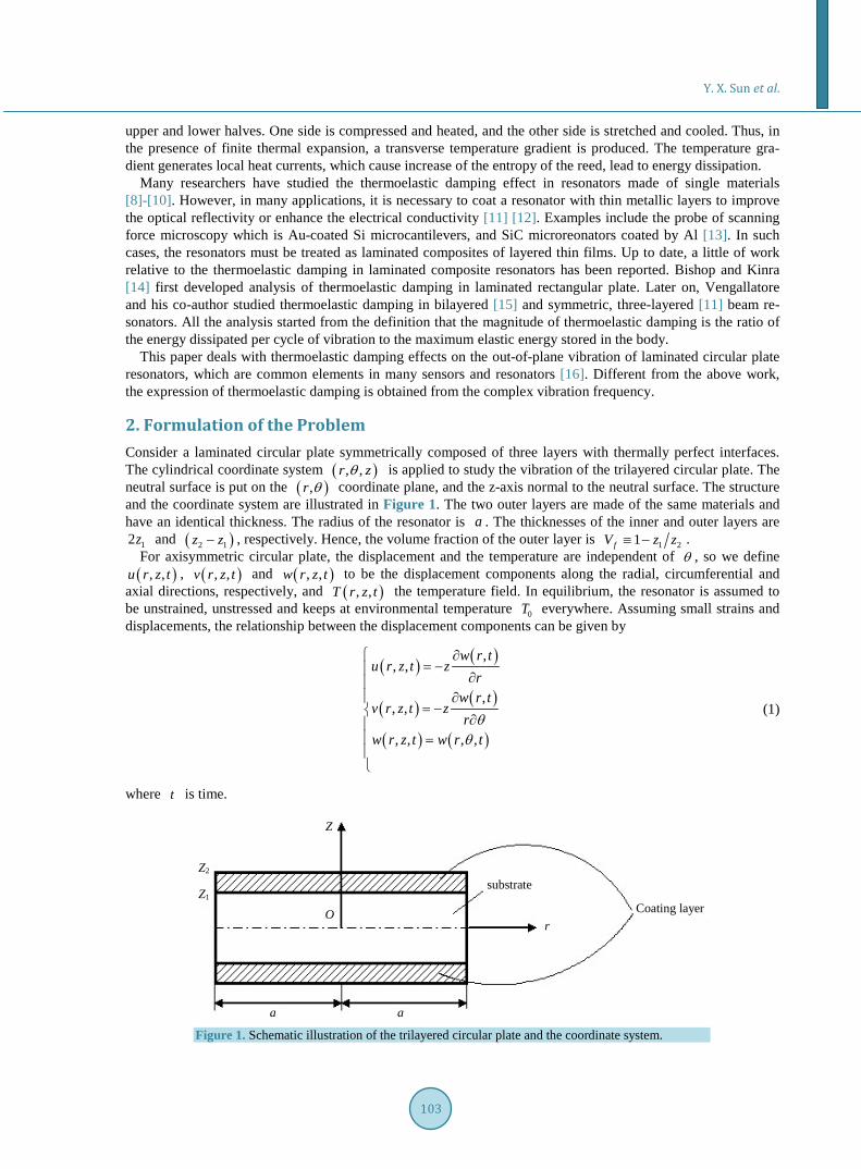
2. Formulation of the Problem Consider a laminated circular plate symmetrically composed of three layers with thermally perfect interfaces. The cylindrical coordinate system ( ), ,r zθ is applied to study the vibration of the trilayered circular plate. The neutral surface is put on the ( ),r θ coordinate plane, and the z-axis normal to the neutral surface. The structure and the coordinate system are illustrated in Figure 1. The two outer layers are made of the same materials and have an identical thickness. The radius of the resonator is a . The thicknesses of the inner and outer layers are
12z and ( )2 1z z− , respectively. Hence, the volume fraction of the outer layer is 1 21fV z z≡ − . For axisymmetric circular plate, the displacement and the temperature are independent of θ , so we define ( ), ,u r z t , ( ), ,v r z t and ( ), ,w r z t to be the displacement components along the radial, circumferential and
axial directions, respectively, and ( ), ,T r z t the temperature field. In equilibrium, the resonator is assumed to be unstrained, unstressed and keeps at environmental temperature 0T everywhere. Assuming small strains and displacements, the relationship between the displacement components can be given by
( ) ( )
( ) ( )
( ) ( )
,, ,
,, ,
, , , ,
w r tu r z t z
rw r t
v r z t zr
w r z t w r tθ
θ
∂= − ∂
∂= −
∂ =
(1)
where t is time.
Z
Z2
Z1
a a
O r
substrate
Coating layer
Figure 1. Schematic illustration of the trilayered circular plate and the coordinate system.

Y. X. Sun et al.
104
The strain components are given by 2
2rwz
rwz
r rθ
ε
ε
∂= − ∂
∂ = − ∂
(2)
We assume plane stresses for the laminated circular plate, which leads to
( ) ( )1 11zj j rj j j Tj j
jθε υ ε ε υ α ϕ
υ = − + + + −
(3)
Thus the cubical dilation je for each layer is obtained as
21 2 11 1
j jj rj j zj Tj j
j
e z wθ
υ υε ε ε α ϕ
υ υ− +
= + + = − ∇ +− −
(4)
where the subscript j ranges from 1 to 3, with the convention that 1j = denotes the substrate layer (the inner layer) and 2,3j = denotes the two covering layers (the outer layers); jυ and Tjα denote the Poisson’s ratio and the coefficient of thermal expansion, respectively; and 0j jT Tϕ = − is the temperature increment of the re-sonator as a function of ( ), ,r z t . 2∇ is the Laplace operator, and is expressed as
22
2
1r rr
∂ ∂∇ = +
∂∂ (5)
Now, the thermal conduction equation containing the thermoelastic coupling term for each layer has the fol-lowing term:
( )2
2 * 202
j jj j j j js H T z w
t tzϕ ϕ
κ ϕ κ∂ ∂ ∂
∇ + = − ∇∂ ∂∂
(6)
where ( ) ( )( )* 20 1 1 1 2j j vj j Tj j j js C E Tρ α υ υ υ = + + − − , ( )1j j Tj jH E α υ= − ; jE ,
jvC and jκ are the Young’s modulus, the specific heat at constant volume and the thermal conductivity , respectively.
Typically, the second item of *js can be ignored. For silicon at 300 K, the ratio of the first item to the second
item of *js is 1776, and the ratios for Au, Al, Cu and Ag are about 30. Although the ratios for metals are not
very large, still we can replace *js by j j vjs Cρ= without introducing large error to the final results. In Section
4, we will first compare the results of the two cases: the heat conduction equation with *js (case I) and that with
js (case II). Noting that thermal gradients in the plane of the cross-section along the plate thickness direction are much
larger than gradients along the radial direction, we can ignore the term 2jϕ∇ in Equation (6) [2]. Hence, Equa-
tion (6) reduces to
( )2
202
j jj j js H T z w
t tzϕ ϕ
κ∂ ∂ ∂
= − ∇∂ ∂∂
(7)
Note that the second term of the right side of Equation (7) is an odd function of z , and the operator 2 2z∂ ∂ on the left side is symmetric in z , it follows that the temperature field jϕ is an odd function of z , and
0jϕ = at 0z = . [14] Thus, it is sufficient to consider only the upper half of the plate, 0z > while solving the thermal conduction Equation (7).
The stress components of each layer are given by the constitutive equation as
( )
( )
2
2 2
2
2 2
11
11
jrj j j Tj j
j
jj j j Tj j
j
E w wz zr rr
E w wz zr r rθ
σ υ υ α ϕυ
σ υ υ α ϕυ
∂ ∂= − + + + ∂− ∂
∂ ∂ = − + + + ∂− ∂
(8)

Y. X. Sun et al.
105
Now, the moments of flexure in the substrate layer are
( )12
1 1 1 1 1 1 120d 1
zr r T T
w wM z z D Mr rr
σ υ υ α ∂ ∂
= = − + + + ∂∂ ∫ (9)
( )12
1 1 1 1 1 1 120d 1
zT T
w wM z z D Mr r rθ θσ υ υ α ∂ ∂
= = − + + + ∂ ∂ ∫ (10)
where ( )3
1 11 2
13 1E zD
υ=
−, 1
1 13 01
3 dz
TM z zz
ϕ= ∫ .
And the moments of flexure in the outer layers are
( )2
1
2
2 2 2 2 2 2 22d 1z
r r T Tz
w wM z z D Mr rr
σ υ υ α ∂ ∂
= = − + + + ∂∂ ∫ (11)
( )2
1
2
2 2 2 2 2 2 22d 1z
T Tz
w wM z z D Mr r rθ θσ υ υ α ∂ ∂
= = − + + + ∂ ∂ ∫ (12)
where ( )( )
3 32 2 1
2 223 1
E z zD
υ
−=
−, 2
12 23 3
2 1
3 dz
T zM z z
z zϕ=
− ∫ .
Hence the resultant moments of flexure of the plate are as follows:
1 2
1 2
r r rM M MM M Mθ θ θ
= += +
(13)
The equation of transverse motion for an axisymmetric circular plate is 2 2
2 2 0rh
M wr t
ρ∂ ∂
− =∂ ∂
(14)
where ( )1 1 2 2 1h z z zρ ρ ρ= + − , and 1ρ and 2ρ are the density of the substrate and covering layers, respec-tively.
Substitute Equations (9)-(13) into Equation (14), we can get the differential equation of the out of plane vibra-tion of the laminated circular plate:
( ) ( ) ( )2
2 2 2 21 2 1 1 1 1 2 2 2 2 21 1 0T T T T h
wD D w D M D Mt
υ α υ α ρ ∂+ ∇ ∇ + + ∇ + + ∇ + =
∂ (15)
In summary, the governing equations of this problem are composed of Equations (7) and (15).
3. Solution of the Governing Equations To calculate the effect of thermoelastic coupling on the vibrations of a circular plate, we solve the coupled thermoelastic Equations (7) and (15) for the case of harmonic vibrations. We set
( ) ( ) ( ) ( ) ( ) ( )i i i1 10 2 200, e , , , , e , , , , et t tw r t w r r z t r z r z t r zϕ ϕ ϕ ϕΩ Ω Ω= = = (16)
where ( )0w r is the mode shape. In general, the frequency Ω is complex, the real part ( )Re Ω giving the new eigenfrequencies of the plate in the presence of thermoelastic coupling effect, and the imaginary part
( )Im Ω giving the attenuation of the vibration. Substituting Equation (16) into Equation (15) yield the following equation:
( ) ( ) ( )2 2 2 2 21 2 0 1 1 1 10 2 2 2 20 01 1 0T T T T hD D w D M D M wυ α υ α ρ+ ∇ ∇ + + ∇ + + ∇ − Ω = (17)

Y. X. Sun et al.
106
where
1 2
110 10 20 203 3 30
1 2 1
3 3d , d .z z
T T zM z z M z z
z z zϕ ϕ= =
−∫ ∫ . (18)
It is assumed that the upper and lower surfaces are adiabatic and the interfaces are thermally perfect. Taking into account the property of jϕ related to z , the boundary and interface conditions are
1
22
1 2 1
1 21 2 1
0, 0
0,
,
,
z
z zz
z z
z zz z
ϕϕ
ϕ ϕϕ ϕ
κ κ
= =∂ = = ∂ = = ∂ ∂
= =∂ ∂
(19)
Following the standard integral transform techniques presented by Özisik [17], the solution of the boundary value problem, in terms of Equation (16), was found to be:
( ) i0 2
1
i, , ei
tnj jn
n nn
Lr z t T
Nϕ φ
γ
∞Ω
=
Ω=
+ Ω∑ (20)
where
( )20 1 1 2 2n n nL w H A H A= ∇ + (21)
1 2
11 1 2 20
d , dz z
n n n nzA z z A z zφ φ= =∫ ∫ (22)
1 2
1
2 21 1 1 2 2 20
d d , 1, 2,z z
n v n v nzN C z C z nρ φ ρ φ= + =∫ ∫ (23)
( ) ( ) ( )1 1 2 1 2 2 2sin , cos sinn n n n na z M a z M a zφ γ φ γ γ= = + (24)
where
( ) ( )( )
( ) ( )( )
1 2 1 11 2
1 2 2 2
1 1 2 2 1 1 2 21 2
2 2 1 2 2 1
, ,
cos cos cos sin,
sin sinn n n n
n n
s s sa a bs
b a z a z b a z a zM M
a z z a z z
κκ κ κ
γ γ γ γγ γ
= = =
= =− −
(25)
The eigenvalues nγ is obtained from the transcendental equation
( ) ( ) ( )( ) ( ) ( )
( ) ( )
1 1 2 1 2 1
1 1 2 1 2 1
2 2 2 2
sin sin cos
cos cos sin 0
0 cos sin
n n n
n n n
n n
a z a z a z
b a z a z a z
a z a z
γ γ γ
γ γ γ
γ γ
− −
− =
−
(26)
From Equations (16) and (20), it is obtained
( )
( )
10 0 121
20 0 221
i,i
i,i
nn
n nn
nn
n nn
Lr z T
NL
r z TN
ϕ φγ
ϕ φγ
∞
=
∞
=
Ω=
+ Ω
Ω=
+ Ω
∑
∑ (27)
Substitution of Equations (18) and (27) into Equation (16) yields,

Y. X. Sun et al.
107
( ) ( )2 2 20 0 0w hD w r w rρ∇ ∇ − Ω = (28)
where
( )
( ) ( )01 2 1 1 2 2
1
1 1 2 22
1
, ,
i , i
w
n n n nn
n nn n
n n
D D f
TD D D f H A H A G F
DH A H A
F GN γ
∞
=
= + Ω
= + Ω = +
+ Ω= =
+ Ω
∑ (29)
For a laminated circular plate with the boundary fully clamped, the boundary conditions are
0
0
0
d0
d
r a
r a
w
wr
=
=
=
=
(30)
The solution of Equation (28) in combination with Equation (30) gives the value of frequency considering thermoelastic coupling effect
( )0 1 fΩ = Ω + Ω (31)
where ( )20 m hq a D ρΩ = is the frequency when the thermoelastic coupling effect is ignored, and
10.21,39.78,89.10,mq = .
Because the difference between Ω and 0Ω is small, we can replace ( )f Ω in Equation (31) by ( )0f Ω and expand Equation (31) into a series up to the first order. That is
( )0 0112
f Ω = Ω + Ω (32)
So, we can easily extract the real and imaginary parts of Ω , which are shown as
( ) ( )2
0 00 1 1 2 2 4 2
1 0
Re 12 n n n
n n
TH A H A F
D γ
∞
=
ΩΩ = Ω + + +Ω
∑ (33)
( ) ( )2
0 00 1 1 2 2 4 2
1 0
Im2
nn n n
n n
TH A H A F
Dγ
γ
∞
=
ΩΩ = Ω + +Ω
∑ (34)
Thus, we arrive at an expression of thermoelastic damping in a symmetric trilayered circular plate, which is given by
( )( )
( )
( )
20 0
1 1 2 2 4 211 0
20 0
1 1 2 2 4 21 0
Im 22 2
Re1
2
nn n n
n n
n n nn n
T H A H A FD
QT H A H A FD
γγ
γ
∞
=−
∞
=
Ω+
Ω +Ω= =
Ω Ω+ +
+Ω
∑
∑ (35)
4. Results and Discussions In this section, we will present some numerical results for the relationship between 1Q− and the radius of the plate and make some discussions about this model. From [11] [18], we can get the thermodynamic properties of the used materials under room temperature (300 K), which are listed in Table 1. For abbreviation, we will only consider the fundamental vibration mode, namely, the 1m = mode.
First, the influence of the reduction of *js to js is checked. The heat conduction equation with *
js is named case I and that with js is named case II. Figure 2 shows the themoelastic damping, 1Q− , against the

Y. X. Sun et al.
108
Table 1. Mechanical and thermal properties of the materials (300 K).
Material ( )PaE ( )1 1J kg KC − −⋅ ⋅ ( )1 1W m Kκ − −⋅ ⋅ ( )1KTα− ( )3kg mρ −⋅ υ
Si 111.6 10× 700 150 62.6 10−× 2300 0.22
Au 108.2 10× 129 320 615 10−× 19300 0.42
Ag 107.6 10× 237 430 618 10−× 10500 0.38
Figure 2. Comparison of the two cases: the heat conduction with *
js , and the heat conduction with js .
radius of the plate, a . The solid line represents the case I, and the dashed line for case II. The structure of the laminate composite is metal/Si/metal and the thickness of the metal and Si layers are 1.11 and 20 µm, respec-tively, which corresponds to 0.1fV = . The metals are Au and Ag in Figure 2(a), Figure 2(b), respectively. It is shown that the results of the two cases are in good agreement.
To verify the accuracy of the model proposed in the paper, we also simulate this problem through the com-mercial software COMSOL Multiphysics. In the calculation, the resonator is composed of Au/Si/Au, the thick-nesses of the Si and Au layers are 20 and 1.11 µm, respectively. We check the slice of the normal strain along the z direction of the circulate plate with the radius of 400 µm, as shown in Figure 3, and find that the strain component zε is nearly zero in the substrate layer of Si, while it varies significantly in the Au layer.
According to this result, the heat conduction equation should be modified into
( )
( )
221 1 1 1
1 1 021
222 2
2 2 2 02
, for the substrate1 2
, for the covering layer
TEs T z wt tz
s H T z wt tz
ϕ ϕ ακ
υ
ϕ ϕκ
∂ ∂ ∂= − ∇ ∂ − ∂∂
∂ ∂ ∂ = − ∇ ∂ ∂∂
(36)
Now, the governing equations are composed of Equations (7) and (43), and the expression of 1Q− can be
obtained through repeating the derivation in Section 3, except for replacing 1H by 1 1
11 2TEαυ−
. This is defined as
Model 2. Correspondingly, the model composed of Equations (7) and (15) is defined as Model 1. Figure 4 shows the calculation results based on Model 1, Model 2 and the finite element method (FEM),
where the abscissa is the plate radius and the ordinate is the thermoelastic damping. It is shown in Figure 4 that the results can be classified into three regions: (1) 500 μma ≤ , the results of
Model 1 and Model 2 are nearer to each other; (2) 500 1200 μma< ≤ , the results of Model 2 and FEM analysis are nearer to each other; (3) 1200 μma > , the results of the three methods are almost the same.
In addition, the variation of 1Q− on the thickness of Si layer is also calculated, and the results are shown in Figure 5. The calculation results based on Model 1, Model 2 and FEM for the structure of Au/Si/Au are com-pared. The radius of the plate is 400 µm in Figure 5(a) and 800 µm in Figure 5(b), and the volume fraction of coating layer is maintained as 0.1fV = .
0.0000 0.0005 0.0010 0.0015 0.00200.0000
0.0001
0.0002
0.0003
0.0004
0.0005
Q-1
a(m)
Heat conduction equation with s*j
Heat conduction equation with sj
Au/Si/Au(a)
0.0000 0.0005 0.0010 0.0015 0.00200.0000
0.0002
0.0004
0.0006
Q-1
a(m)
Heat conduction equation with s*
j
Heat conduction equation with sj
(b) Ag/Si/Ag

Y. X. Sun et al.
109
Figure 3. Slice of the normal strain zε .
Figure 4. Comparison of the analytical solution and FEM analysis.
Comparing Figure 4, Figure 5, it is shown that the three regions in Figure 4 are related to the value of 1a z .
In the case of small value of 1a z , the results of Model 1 and Model 2 are nearer to each other. On the other hand, in the case of large value of 1a z , the results of Model 2 and FEM analysis are nearer to each other.
In summarize, the results of both models are in good agreement with FEM results, and those of Model 2 agree better than those of Model 1. To further illustrate the influence of the normal strain along the z direction, the distribution of zε at the center of the plate along the z direction is calculated for plates with different radius. The variation tendency of zε on z is the same for plates with different radius. As an example, the results for the plate with the radius of 200 and 400 µm are shown in Figure 6. It can be found that the normal strain in Si layer is quite small, however, the strain in Au layer is much larger, and it increases suddenly at the interface. At the interface, the ratio of the strain of Si layer, Siε , to that of Au layer, Auε , increases a little as the radius of

Y. X. Sun et al.
110
Figure 5. Variation of 1Q− on the thickness of Si layer based on Model 1, Model 2 and FEM. The radius of the plate is (a)
400 μma = , (b) 800 μma = .
Figure 6. Distribution of zε at the center of the plate along the z direction for the plates with radius of 200 and 400 µm.
the plate increases. The value is about 0.38. So, we can ignore the normal strain zε in Si layer and obtain good results, as shown in Figure 4.
5. Conclusion As MEMS and NEMS technologies evolve, there is an increasing use of sophisticated structural geometries and advanced materials, especially laminated composites of layered thin film. A detailed theory is presented for thermoelastic damping in trilayered circular plate resonators. The analytical expression for thermoelastic damp-ing in these structures is obtained. Then the accuracy of the model is verified through comparison with finite element analysis results and some simplifications are made on the theory. In the heat conduction equation, the coefficient of ratio of temperature obtained from the plane stress assumption is composed of two items. It is found that the equation can be simplified by ignoring the item related to mechanical deformation. In addition, the strain along the thickness direction of Silicon can be ignored. Finally, the model is accurate for thin plate structures. However, the Mindlin model should be used for thick plate to derive the expression of thermoelastic damping.
Acknowledgements The work described in this paper is financially supported by the National Natural Science Foundation of China under grant number 11002017 and 11032001 and the Fundamental Research Funds for the Central Universities
0 5 10 15 20
-0.02
-0.01
0.00
0.01
0.02
ε z
z (µm)
a=200µm a=400µm

Y. X. Sun et al.
111
under grant number YWF-13-JQCI-001. The authors would like to gratefully acknowledge these supports.
References [1] Srikar, V.T. and Spearing, S.M. (2003) Materials Selection in Micromechanical Design: An Application of the Ashby
Approach. Journal of Microelectromechanical Systems, 12, 3-10. http://dx.doi.org/10.1109/JMEMS.2002.807466 [2] Sun, Y.X. and Tohmyoh, H. (2009) Thermoelastic Damping of the Axisymmetric Vibration of Circular Plate Resona-
tors. Journal of Sound and Vibration, 319, 392-405. http://dx.doi.org/10.1016/j.jsv.2008.06.017 [3] Lifshitz, R. and Roukes, M.L. (2000) Thermoelastic Damping in Micro- and Nanomechanical Systems. Physical Re-
view B, 61, 5600-5609. http://dx.doi.org/10.1103/PhysRevB.61.5600 [4] Srikar, V.T. and Spearing, S.M. (2003) Material Selection for Microfabricated Electrostatic Actuators. Sensors and
Actuators A, 102, 29-85. http://dx.doi.org/10.1016/S0924-4247(02)00393-X [5] Ferguson, A.T., Li, L. and Nagaraj, V.T. (2005) Modeling and Design of Composite Free-Free Beam Piezoelectric
Resonators. Sensors and Actuators A, 118, 63-69. http://dx.doi.org/10.1016/j.sna.2004.08.001 [6] Evoy, S., Olkhovets, A. and Sekaric, L. (2000) Temperature-Dependent Internal Friction in Silicon Nanoeletrome-
chanical Systems. Applied Physics Letters, 77, 2397-2399. http://dx.doi.org/10.1063/1.1316071 [7] Zener, C. (1937) Internal Friction in Solids I. Theory of Internal Friction in Reeds. Physical Review, 52, 230-235.
http://dx.doi.org/10.1103/PhysRev.52.230 [8] Sun, Y.X. and Saka, M. (2010) Thermoelastic Damping in Micro-Scale Circular Plate Resonators. Journal of Sound
and Vibration, 329, 328-337. http://dx.doi.org/10.1016/j.jsv.2009.09.014 [9] Sun, Y.X., Fang, D.N. and Soh, A.K. (2006) Thermoelastic Damping in Micro-Beam Resonators. International Jour-
nal of Solids and Structures, 43, 3213-3229. http://dx.doi.org/10.1016/j.ijsolstr.2005.08.011 [10] Wong, S.J., Fox, C.H.J. and McWilliam, S. (2006) Thermoelastic Damping of the In-Plane Vibration of thin Silicon
Rings. Journal of Sound and Vibration, 293, 266-285. http://dx.doi.org/10.1016/j.jsv.2005.09.037 [11] Vengallatore, S. (2005) Analysis of Thermoelastic Damping in Laminated Composite Micromechanical Beam Reso-
nators. Journal of Micromechanics and Microengineering, 15, 2398-2404. http://dx.doi.org/10.1088/0960-1317/15/12/023
[12] Bao, G. and Jiang, W. (1998) A Heat Transfer Analysis for Quartz Microresonator IR Sensors. International Journal of Solids and Structures, 35, 3635-3653. http://dx.doi.org/10.1016/S0020-7683(97)00235-7
[13] Huang, X.M.H., Zorman, C.A. and Mehregany, M. (2003) Nanodevice Motion at Microwave Frequencies. Nature, 421, 496. http://dx.doi.org/10.1038/421496a
[14] Bishop, J.E. and Kinra, V.K. (1997) Elastothermodynamic Damping in Laminated Composites. International Journal of Solids and Structures, 34, 1075-1092. http://dx.doi.org/10.1016/S0020-7683(96)00085-6
[15] Prabhakar, S. and Vengallatore, S. (2007) Thermoelsatic Damping in Bilayered Micromechanical Beam Resonators. Journal of Micromechanics and Microengineering, 17, 532-538. http://dx.doi.org/10.1088/0960-1317/17/3/016
[16] Berry, B.S. (1995) Precise Investigation of the Theory of Damping by Transverse Thermal Currents. Journal of Ap-plied Physics, 26, 1221-1224. http://dx.doi.org/10.1063/1.1721877
[17] Özisik, M. (1980) Heat Conduction. John Wiley & Sons, New York. [18] Ashby, M.F. (2001) Materials Selection in Mechanical Design. Butterworth Heinemann, Oxford.