a theoretical study in maximizing crude unit kerosene€¦ · a theoretical study in maximizing...
TRANSCRIPT
Page 1 of 11 This publication is the intellectual property of MPEC, Inc., Houston, Texas
A Theoretical Study in Maximizing Crude Unit Kerosene
W. Doug McDaniel, MPEC, Inc., Feb. 26, 2014, Ver. 1 (email address: [email protected])
Introduction
Not long ago I was asked how low the D-86 90% point of a Crude Unit overhead naphtha stream should be for a “good” Crude Unit operation where kerosene was worth substantially more than naphtha. I had seen what I considered both “good” and “bad” operations, but wasn’t really sure. I knew “typical” numbers, but I hadn’t ever done a study to document how low it “should” be, or how much kerosene could be recovered from a typical crude, both theoretically, and practically. This exercise was intended to fill in that knowledge gap.
Summary Conclusion
It turns out that surprisingly large amounts of kerosene are not normally being recovered due to the fairly poor fractionation typical in most existing Crude Units. Per this exercise, assuming a 105°F flash kerosene with a 550°F D-86 endpoint, and 100,000 BPSD of a sample light crude (~39 API gravity), only 26,185 BPSD of dry kerosene is produced out of 33,900 BPSD theoretically possible with infinite fractionation. This exercise further shows two possible configurations that increase kerosene to 28,940 BPSD by adding a Kerosene Fractionator to the Crude Unit, and further to 32,760 by adding an additional Diesel Fractionator. Adding just the Kerosene Fractionator decreases the naphtha make by 2,500 BPSD. (The rest of the additional kerosene comes from diesel, resulting in a loss of 78 BPSD of diesel to AGO.) If the 2,500 BPSD upgrade of naphtha to kerosene is valued at $20/BBL (ignoring the diesel loss), then this is worth $17.5 MM/Yr. The total duty of the Kerosene Fractionator’s reboiler is substantial at 59.9 MM BTU/Hr, but using 75% efficiency and $4/MM BTU, this only amounts to $2.7 MM/Yr. Eliminating the Kerosene Steam Stripper also saves 10,000 #/Hr of steam worth $0.4 MM/Yr at $5.0/M#. Since this is a net value of $15.2 MM/Yr, it would seem that this idea should be well worth pursuing, especially if an idle column is available. If kerosene is more highly valued than diesel, then adding the Diesel Fractionator might also be beneficial. Adding the Diesel Fractionator recovers 441 BPSD more naphtha to kerosene, but it also loses 1,569 BDSD of additional diesel to AGO.
Maximum Theoretical Recovery
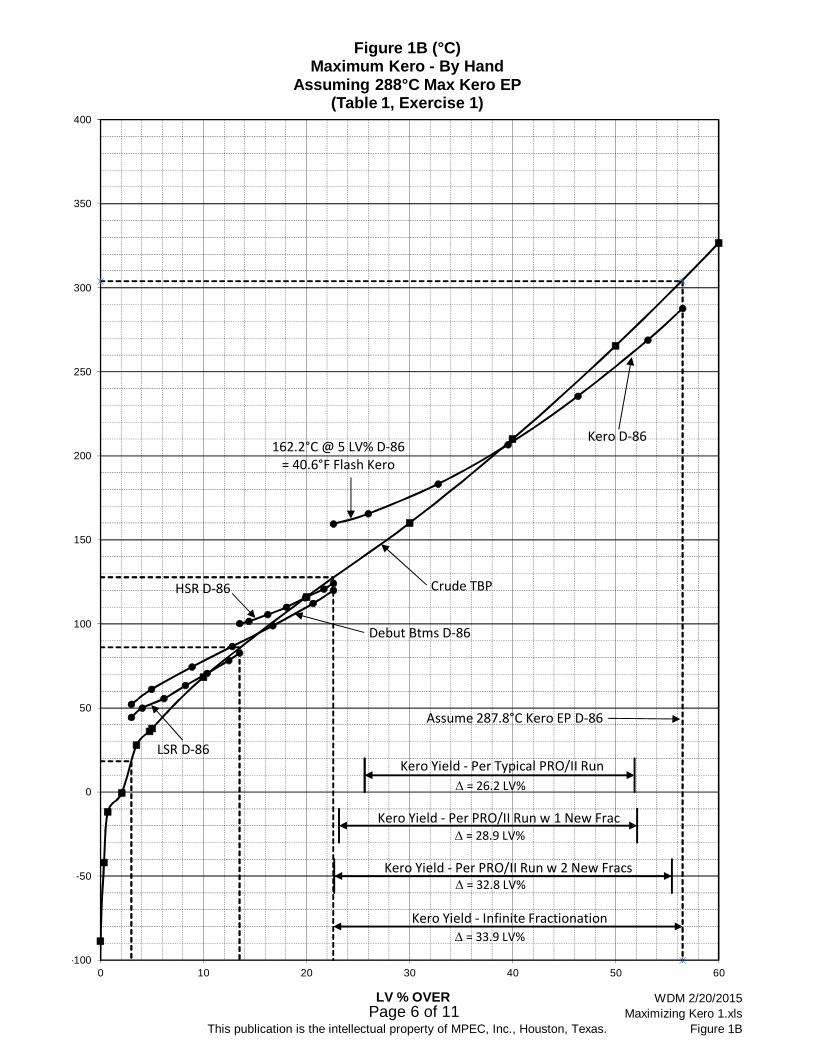
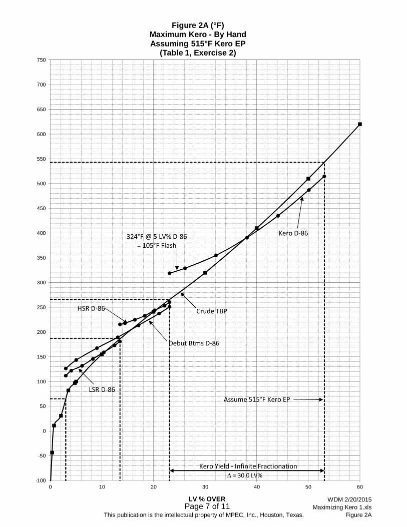
Table 1 and Figures 1A through 2B present two exercises of determining maximum theoretical kerosene recovery with infinite fractionation. Both exercises assume a front-end limiting kerosene flash point specification of 105°F. In Exercise 1 (at the top of Table 1, and graphed on Figures 1A in °F and 1B in °C), the limiting kerosene D-86 EP of 550°F was used, and in Exercise 2 (at the bottom of Table 1, and graphed on Tables 2A in °F and 2B in °C) a lighter limiting kerosene D-86 EP of 515°F was used.
Page 2 of 11 This publication is the intellectual property of MPEC, Inc., Houston, Texas
By infinite fractionation definition, all the product TBP’s fall directly on top of the crude TBP. Assuming starting and ending LV% kerosene cutpoints on crude, the D-86 distillation curve was then hand calculated from the TBP using the 1963 ASTM conversion method (which MPEC prefers). This was redone by trial-and-error until the resulting D-86 5% point was 324°F (consistent with a 105°F flash point by correlation), and the D-86 EP was the desired 550°F or 515°F. The cutpoint between LPG and LSR was set at 65°F, and the cutpoint between LSR and HSR naphtha was set at 187°F. The TBP’s of the LSR, HSR, and Debut Btms (LSR+HSR) were then also defined as equal to the crude TBP, and they were converted to D-86’s.
As seen in Exercise 1 of Table 1 and Figures 1A &1B for 550°F EP kerosene, the 90% D-86 point of the lightest possible Debut Btms utilizing infinite fractionation would be 234.0°F, and the kerosene cutpoints for this particular example light crude would be from 22.6 to 56.5 LV%, yielding 33.9 LV% on crude. As seen in Exercise 2 of Table 1 and Figures 2A & 2B, making the lighter 515°F endpoint kerosene decreases recovery greatly from the back-end, but only slightly from the front-end. In Exercise 2, the 90% D-86 point of the lightest possible Debut Btms utilizing infinite fractionation would be 237.5°F, and the kerosene cutpoints would be from 23.1 to 53.1 LV%, yielding 30.0 LV% of crude.
Typical Crude Column Maximizing Kerosene
Figure 3 summarizes a PRO/II run of a typical “good” Crude Unit operation to maximize kerosene with a 105°F flash and a 550°F D-86 EP, consistent with Exercise 1 above. Even though this operation probably has more theoretical stages and OH reflux than most crude columns, note that the 90% D-86 point for the Deb Btms (from the OH Naphtha) is 263°F, or 29°F higher than theoretically possible. Note too, that the dry kerosene yield is much lower than theoretical at only 26,185 BPSD from 100,000 BPSD of charge, for 26.2 LV% on crude (vs. 33.9 LV% theoretical). This yield is shown on Figures 1A & 1B as the “Kero Yield – Per Typical PRO/II Run“ line.
Maximizing Kerosene by Adding a Kerosene Fractionator
Figure 4 summarizes a PRO/II run of the same typical Crude Unit, but with a 12’ Ø Kerosene Fractionator replacing the 6.5’ Ø Kerosene Stripper. This does not recover all the theoretical kerosene, but it is a first-pass, not-yet-optimized attempt to put what is practical into perspective for recovering naphtha to kerosene without trying to recover diesel to kerosene. As seen, this recovers 28,940 BPSD of dry kerosene, or 28.9 LV% of crude. This yield is shown on Figures 1A & 1B as the “Kero Yield – Per PRO/II Run w 1 New Frac” line. To achieve this, heavy naphtha has been dropped down to the kerosene draw for much sharper fractionation OH in the Kerosene Fractionator. This recovers 2,500 BPSD of naphtha into kerosene. Holding the kerosene endpoint constant at 550°F, 223 BPSD of diesel is also moved to kerosene, as well. Holding the 640°F 90% point on diesel requires the loss of some diesel to AGO, but this loss is only 78 BPSD.
The total duty of the new Kerosene Fractionator is substantial at 59.9 MM BTU/Hr, but using 75% efficiency and $4/MM BTU, this only amounts to $2.7 MM/Yr. This can also be partially

Page 3 of 11 This publication is the intellectual property of MPEC, Inc., Houston, Texas
offset by integrating the new column’s OH condenser and reboiler into the Crude Unit’s exchanger system for crude preheat and product cooling. Eliminating the Kerosene Steam Stripper also saves 10,000 #/Hr of steam worth $0.4 MM/Yr at $5.0/M#. Making the lighter Crude Column OH has greatly increased offgas from the OH Receiver, but this gets reabsorbed by compressing it to 50 psig and recontacting it with the OH naphtha. Since this additional compression requires only 285 additional BHP, its incremental cost at 10¢/KWH is only $0.2 MM/Yr.
Maximizing Kerosene with an Additional Diesel Fractionator
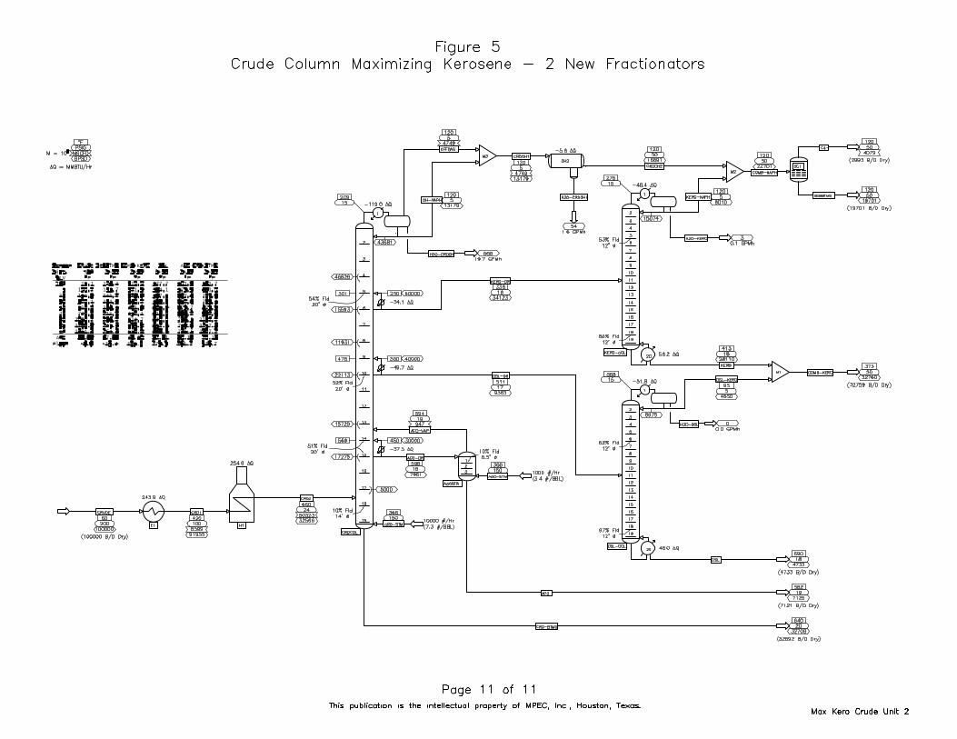
Figure 5 summarizes a PRO/II run of the same typical Crude Unit, but with 12’ Ø fractionators replacing both the 6.5’ Ø Kerosene and Diesel Side Strippers. This has still not recovered all the theoretical kerosene, but, again, it is only a first-pass, not-yet-optimized attempt to put what is practical into perspective. As seen, this recovers 32,759 BPSD of dry kerosene, or 32.8 LV% of crude. This yield is shown on Figures 1A & 1B as the “Kero Yield – Per PRO/II Run w 2 New Frac’s” line. To achieve this additional recovery, heavy kerosene has been dropped down to the diesel draw for much sharper fractionation OH in the Diesel Fractionator.
The total duty of the new Kerosene Fractionator and the Diesel Fractionator reboilers is substantial at 102.2 MM BTU/Hr, but using 75% efficiency and $4/MM BTU, this only amounts to $4.6 MM/Yr. This can also be partially offset by integrating the new column’s OH condensers and reboilers into the Crude Unit’s exchanger system for crude preheat and product cooling. Eliminating the Steam Strippers also saves 12,500 #/Hr of steam worth $0.5 MM/Yr at $5.0/M#.
When kerosene and diesel are evenly valued, the only purpose of the Diesel Fractionator is to recover diesel to kerosene so that more naphtha can be recovered to kerosene, and this option recovers 441 BPSD of additional naphtha as kerosene. However, Figure 5 shows that taking so much kerosene out of diesel, while maintaining the diesel D-86 90% point at 640°F, has greatly decreased diesel yield and increased the dry AGO yield by an additional 1,565 BPSD. It may be that diesel with a heavier 90% point than 640°F can still be made as viable product. For instance, if substantial kerosene is blended into the Refinery’s diesel product, then it is only the blended Refinery diesel product that must be maintained at the 90% point, substantially reducing this loss to AGO. If diesel is recovered in the Vacuum Unit, it may also be that AGO can be routed to the Vacuum Unit’s HVGO PA for better splitting between diesel and AGO than can be done in the Crude Column to further offset this loss.
If none of these heavier diesel options are viable, then the economics of the Diesel Fractionator will probably not merit its installation. Of course, optimization of any new fractionators will greatly depend on your particular crude TBP, Crude Unit configuration, product values, product specifications, product blending, and utility costs.

Table 1"Hand" Method for Maximum Possible Kerosene Yield
Exercise 1 - See Figures 1A & 1BCrude TBP Assume Max Kero D-86 LPG's LSR Naph Hvy Naph Kerosene
Example Light Crude EP of 550°F (288°C) LV% °F °C LV% °F °C LV% °F °C LV% °F °C(PRO/II Input) 0 65 18.3 0 187 86.1 0 262 127.8 0 579 303.9
LV% °C °F 3 65 18.3 13.5 187 86.1 22.6 262 127.8 56.5 579 303.90.00 -161.49 -258.68 3 -148 -100.0 13.5 -148 -100.0 22.6 -148 -100.0 56.5 -148 -100.00.01 -88.60 -127.480.35 -42.04 -43.670.72 -11.72 10.90 Convert LSR TBP to D-86 Per ASTM 1963 (By Hand) LV% on Convert Deb Btms TBP to D-86 Per ASTM 1963 (By Hand) LV% on 2.06 -0.50 31.10 LV% TBP °F TBP °F 50% D86 °F D-86 °F Crude TBP D-86 °C LV% TBP °F TBP °F 50% D86 °F D-86 °F Crude TBP D-86 °C3.50 27.84 82.12 0 65.0 25.00 10.0 112.0 3.00 44.4 0 65.0 35.00 16.0 126.0 3.00 52.24.75 36.07 96.93 10 90.0 23.00 10.0 122.0 4.05 50.0 10 100.0 43.00 24.0 142.0 4.96 61.15.00 37.78 100.00 30 113.0 24.00 14.0 132.0 6.15 55.6 30 143.0 37.00 22.0 166.0 8.88 74.4
10.00 68.33 155.00 50 137.0 9.00 146.0 8.25 63.3 50 180.0 8.00 188.0 12.80 86.720.00 116.11 241.00 70 157.5 20.50 13.0 159.0 10.35 70.6 70 213.0 33.00 22.0 210.0 16.72 98.930.00 160.00 320.00 90 177.5 20.00 14.0 173.0 12.45 78.3 90 245.5 32.50 24.0 234.0 20.64 112.240.00 210.00 410.00 100 187.0 9.50 8.0 181.0 13.50 82.8 100 262.0 16.50 14.0 248.0 22.60 120.050.00 265.56 510.0060.00 326.67 620.00 Convert HSR TBP to D-86 Per ASTM 1963 (By Hand) LV% on Convert Kero TBP to D-86 Per ASTM 1963 (By Hand) LV% on 70.00 393.33 740.00 LV% TBP °F TBP °F 50% D86 °F D-86 °F Crude TBP D-86 °C LV% TBP °F TBP °F 50% D86 °F D-86 °F Crude TBP D-86 °C80.00 465.56 870.00 0 187.0 7.00 2.5 212.5 13.50 100.3 0 262.0 26.00 11.0 319.0 22.60 159.490.00 565.56 1050.00 10 194.0 16.00 7.0 215.0 14.41 101.7 10 288.0 55.00 32.0 330.0 25.99 165.695.00 648.89 1200.00 30 210.0 14.00 8.0 222.0 16.23 105.6 30 343.0 61.00 42.0 362.0 32.77 183.398.00 732.22 1350.00 50 224.0 6.00 230.0 18.05 110.0 50 404.0 0.00 404.0 39.55 206.7
100.00 815.56 1500.00 70 241.0 17.00 10.0 240.0 19.87 115.6 70 471.0 67.00 52.0 456.0 46.33 235.6
90 255.0 14.00 9.5 249.5 21.69 120.8 90 541.0 70.00 60.0 516.0 53.11 268.9100 262.0 7.00 6.0 255.5 22.60 124.2 100 579.0 38.00 34.0 550.0 56.50 287.8
Graph PRO/II Kero Yield Ranges - 550°F EP
Typical Run: LV% °F °C Exercise 2 - See Figures 2A & 2BStart 25.642 60.00 20.00 Assume Lower Kero D-86 LPG's LSR Naph Hvy Naph Kerosene
Start 25.642 20.00 0.00 EP of 515°F (268°C) LV% °F °C LV% °F °C LV% °F °C LV% °F °CEnd 51.827 60.00 20.00 0 65 18.3 0 187 86.1 0 266 130.0 0 543 283.9End 51.827 20.00 0.00 3 65 18.3 13.5 187 86.1 23.1 266 130.0 53.1 543 283.9Start 25.642 40.00 10.00 3 -148 -100.0 13.5 -148 -100.0 23.1 -148 -100.0 53.1 -148 -100.0End 51.827 40.00 10.00
Max w 2 Frac: LV% °F °C Convert LSR TBP to D-86 Per ASTM 1963 (By Hand) LV% on Convert Deb Btms TBP to D-86 Per ASTM 1963 (By Hand) LV% on Start 22.694 -20.00 -40.00 LV% TBP °F TBP °F 50% D86 °F D-86 °F Crude TBP D-86 °C LV% TBP °F TBP °F 50% D86 °F D-86 °F Crude TBP D-86 °CStart 22.694 -60.00 -60.00 0 65.0 25.00 10.0 112.0 3.00 44.4 0 65.0 36.00 17.0 126.5 3.00 52.5End 55.453 -20.00 -40.00 10 90.0 23.00 10.0 122.0 4.05 50.0 10 101.0 44.00 24.0 143.5 5.01 61.9End 55.453 -60.00 -60.00 30 113.0 24.00 14.0 132.0 6.15 55.6 30 145.0 36.50 22.0 167.5 9.03 75.3Start 22.694 -40.00 -50.00 50 137.0 9.00 146.0 8.25 63.3 50 181.5 8.00 189.5 13.05 87.5End 55.453 -40.00 -50.00 70 157.5 20.50 13.0 159.0 10.35 70.6 70 217.0 35.50 24.0 213.5 17.07 100.8
90 177.5 20.00 14.0 173.0 12.45 78.3 90 249.5 32.50 24.0 237.5 21.09 114.2Max w 1 Frac: LV% °F °C 100 187.0 9.50 8.0 181.0 13.50 82.8 100 266.0 16.50 13.5 251.0 23.10 121.7
Start 23.142 20.00 -10.00Start 23.142 -20.00 -30.00 Convert HSR TBP to D-86 Per ASTM 1963 (By Hand) LV% on Convert Kero TBP to D-86 Per ASTM 1963 (By Hand) LV% on End 52.082 20.00 -10.00 LV% TBP °F TBP °F 50% D86 °F D-86 °F Crude TBP D-86 °C LV% TBP °F TBP °F 50% D86 °F D-86 °F Crude TBP D-86 °CEnd 52.082 -20.00 -30.00 0 187.0 7.00 2.5 215.5 13.50 101.9 0 266.0 23.50 10.0 319.0 23.10 159.4Start 23.142 0.00 -20.00 10 194.0 16.00 7.0 218.0 14.46 103.3 10 289.5 48.00 26.0 329.0 26.10 165.0End 52.082 0.00 -20.00 30 210.0 16.00 8.0 225.0 16.38 107.2 30 337.5 53.50 36.0 355.0 32.10 179.4
50 226.0 7.00 233.0 18.30 111.7 50 391.0 0.00 391.0 38.10 199.4Infinite Frac: LV% °F °C 70 244.0 18.00 11.0 244.0 20.22 117.8 70 449.0 58.00 44.0 435.0 44.10 223.9
Start 22.600 -80.00 -80.00 90 258.0 14.00 9.5 253.5 22.14 123.1 90 511.0 62.00 52.0 487.0 50.10 252.8End 56.500 -80.00 -80.00 100 266.0 8.00 7.0 260.5 23.10 126.9 100 543.0 32.00 28.0 515.0 53.10 268.3
Page 4 of 11This publication is the intellectual property of MPEC, Inc., Houston, Texas. WDM 2/20/2015 Maximizing Kero 1.xls - Table 1

Page 5 of 11This publication is the intellectual property of MPEC Inc., Houston, Texas.
WDM 2/20/2015 Maximizing Kero 1.xls
Figure 1A
-100
-50
0
50
100
150
200
250
300
350
400
450
500
550
600
650
700
750
0 10 20 30 40 50 60
LV % OVER
Figure 1A (°F)Maximum Kero - By Hand
Assuming 550°F Max Kero EP(Table 1, Exercise 1)
324°F @ 5 LV% D‐86= 105°F Flash
Assume 550°F Kero EP D‐86
LSR D‐86
HSR D‐86
Debut Btms D‐86
Kero Yield ‐ Per Typical PRO/II Run
Kero Yield ‐ Per PRO/II Run w 2 New Frac's
Crude TBP
Kero D‐86
Kero Yield ‐ Infinite Fractionation
= 26.2 LV%
= 33.9 LV%
= 32.8 LV%
Kero Yield ‐ Per PRO/II Run w 1 New Frac = 28.9 LV%
Page 6 of 11This publication is the intellectual property of MPEC, Inc., Houston, Texas.
WDM 2/20/2015 Maximizing Kero 1.xls
Figure 1B
-100
-50
0
50
100
150
200
250
300
350
400
0 10 20 30 40 50 60
LV % OVER
Figure 1B (°C)Maximum Kero - By Hand
Assuming 288°C Max Kero EP(Table 1, Exercise 1)
162.2°C @ 5 LV% D‐86= 40.6°F Flash Kero
HSR D‐86
Debut Btms D‐86
Crude TBP
LSR D‐86
Assume 287.8°C Kero EP D‐86
Kero Yield ‐ Per Typical PRO/II Run
Kero Yield ‐ Per PRO/II Run w 2 New Fracs
Kero D‐86
Kero Yield ‐ Infinite Fractionation
= 26.2 LV%
= 32.8 LV%
= 33.9 LV%
Kero Yield ‐ Per PRO/II Run w 1 New Frac = 28.9 LV%
Page 7 of 11This publication is the intellectual property of MPEC, Inc., Houston, Texas.
WDM 2/20/2015 Maximizing Kero 1.xls
Figure 2A
-100
-50
0
50
100
150
200
250
300
350
400
450
500
550
600
650
700
750
0 10 20 30 40 50 60
LV % OVER
Figure 2A (°F)Maximum Kero - By HandAssuming 515°F Kero EP
(Table 1, Exercise 2)
324°F @ 5 LV% D‐86= 105°F Flash
Assume 515°F Kero EP
LSR D‐86
HSR D‐86
Debut Btms D‐86
Crude TBP
Kero D‐86
Kero Yield ‐ Infinite Fractionation = 30.0 LV%

Page 8 of 11This publication is the intellectual property of MPEC, Inc., Houston, Texas.
WDM 2/20/2015 Maximizing Kero 1.xls
Figure 2B
-100
-50
0
50
100
150
200
250
300
350
400
0 10 20 30 40 50 60
LV % OVER
Figure 2B (°C)Maximum Kero - By HandAssuming 268°C Kero EP
(Table 1, Exercise 2)
162.2°C @ 5 LV% D‐86= 40.6°F Flash Kero
HSR D‐86
Debut Btms D‐86
Crude TBP
LSR D‐86
Assume Current Kero EP
Kero D‐86
= 30.0 LV%
Kero Yield ‐ Infinite Fractionation