a thermoeiastic transversely isotropic thick walled ... · pdf filea thermoeiastic...
TRANSCRIPT
NASA Technical Mernorandu_m 102320
A Thermoeiastic Transversely Isotropic
Thick Walled Cylinder/Disk
Application: An AnalyticalSolution and Study
S.M. Arnold
Lewis Research Center
Cleveland, Ohio ' _
October 1989
(NASA-TM-I023_O) A THERMOELASTIC
TRANSVERSELY IS_TROPIC THICK gALLED
CYLINOER/DISK APPLICATION: AN ANALYTICAL
SOLUTION AND STUDY (NASA) 46 p CSCL
N90-12950
20K Unclas
G3/3q 0240384
https://ntrs.nasa.gov/search.jsp?R=19900003634 2018-05-07T04:34:42+00:00Z
t
l
I
............... _ T---- -- --- _

A THERMOELASTIC TRANSVERSELY ISOTROPIC THICK WALLED CYLINDER/
DISK APPLICATION: AN ANALYTICAL SOLUTION AND STUDY
S.M. Arnold
National Aeronautics and Space AdministrationLewis Research Center
Cleveland, Ohio 44135
ABSTRACT
A continuum theory is utilized to represent the thermoelastic behavior of a thickwalled composite cylinder that can be idealized as transversely isotropic. A multiaxial
statement of the constitutive theory employed is presented, as well as, the out of the planeof isotropy, plane stress and plane strain reductions. The derived analytical solutionpresented is valid for a cylindrical tube or thin disk with a concentric hole, subjected tointernal and/or external pressure and a general radial temperature distribution. A specific
problem examined is that of a thick walled cylinder subjected to an internal and externalpressure loading and a linear radial temperature distribution. The results are expressed innondimensional form and the effects on the response behavior are examined for various
material properties, fiber orientation and types of loadings.
INTRODUCTION
Recently, a continuum theory was presented for representing the thermoelastic
behavior of unidirectional composites which can be idealized as a locally transverse
isotropic homogeneous continua [1]. Applicability of a continuum theory for predicting
deformations of composite (textured) materials depends relatively upon characteristic
structural dimensions, the severity of gradients (i.e. stress, temperature, etc.), and the
relative scale and periodicity of the material's internal structure.
tIere, application of this transversely isotropic theory is made to the plane strain
problem of a thick walled cylindrical tube subjected to internal and external pressure and a
radial temperature distribution. The corresponding problem of a thin disk (plane stress
case) with a concentric hole is also considered. Motivation for selecting the thick walled
cylinder problem for investigation was twofold. The first is that it provides a simple
structure that can be solved analytically, thereby supplying a benchmark problem for
structural analysis code verification. Secondly, the thrust chambers of reusable rocket
engines, notably the NASA Space Shuttle main engine, and tubular composite test
specimens may be geometrically idealized as such. This enables a qualitative examination
of the effect of fiber reinforcement on the stress, strain and deformation distributions.

The presentstudy will be confinedto examiningthe effectof material properties,
fiber orientation and type of loading (in a generalnon-dimensional setting) on the
thermoelasticbehaviorof a cylinder soasto developan intuition with regardto the effects
of transverseisotropy. In particular four typesof pressureloadings(i.e. interior only,
exterior lessthan interior, uniform and exterior greaterthan interior) and three types of
linear radial temperatureprofiles (i.e. inner surfacehotter than outer, uniform, and outer
surfacehotter than inner) will beexamined.
This study beginswith a brief descriptionof the thermoelastictransverselyisotropic
constitutive theory and its planestrain and planestresssimplification. Next the analytical
solution is presentedin generalform and then in a normalizedform for a specificlinear
radial temperaturedistribution. A limited parametric study is then presented.
CONSTITUTIVE EQUATIONS
Given a linear hyperetasticmaterial reinforcedby a singlefamily of fibers the stressand strain componentscanbe related through a normality structure utilizing a
complementaryenergyfunction fl(aij,didj,T), i.e.
Oil (1)eiJ = Oa..
1.1
Here aij denotes the components of (Cauchy) stress, eij the components of infinitesimal
strain and the symmetric tensor d.d. is formed by a self product of the unit vector di,1jwhich denotes the local fiber direction and T represents temperature.
As discussed in [1] the complementary energy function may be expressed as:
fl(_ij,didj) =AP 1 +BP2+CP3+DP4+EP 5
+ (FI I+HI4) AT (2)
where
2
P1 = I1
P22 2
=I2_i5+_1 (i4 _911+6ili4)4
2
2
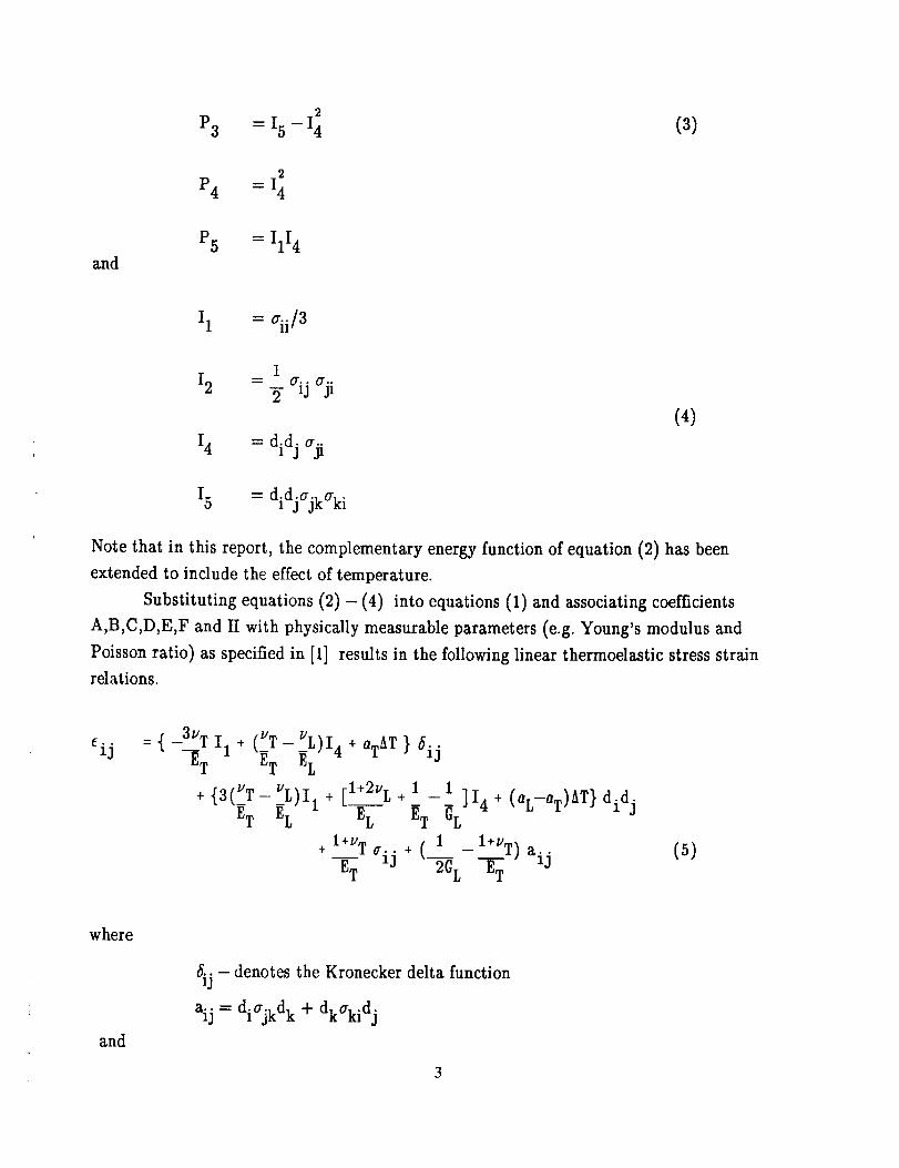
P3 = I5-I4 (3)
2
P4 = I4
and
P5 = IlI4
I 1 = ¢ii/3
112 =_ aij aji
2
14 = did j aji
(4)
15 = didjajkaki
Note that in this report, the complementary energy function of equation (2) has been
extended to include the effect of temperature.
Substituting equations (2) - (4) into equations (1) and associating coefficients
A,B,C,D,E,F and H with physically measurable parameters (e.g. Young's modulus and
Poisson ratio) as specified in [1] results in the following linear thermoelastic stress strain
relations.
_. °
13 : {-3__VTI1 + (_VT-_VL)I4 + aTAT ) 6ij
ET ET EL
+ {3(VT__VL)ll + [l+2vL +l _i ]14 + (aL_aT)AT) didj
gT EL EL GL
+ l+vT 1 l+VT)ET crij + ( - aijm 2GL ET
(5)
where
and
/iij - denotes the Kronecker delta function
aij = diajkd k + dkakid j
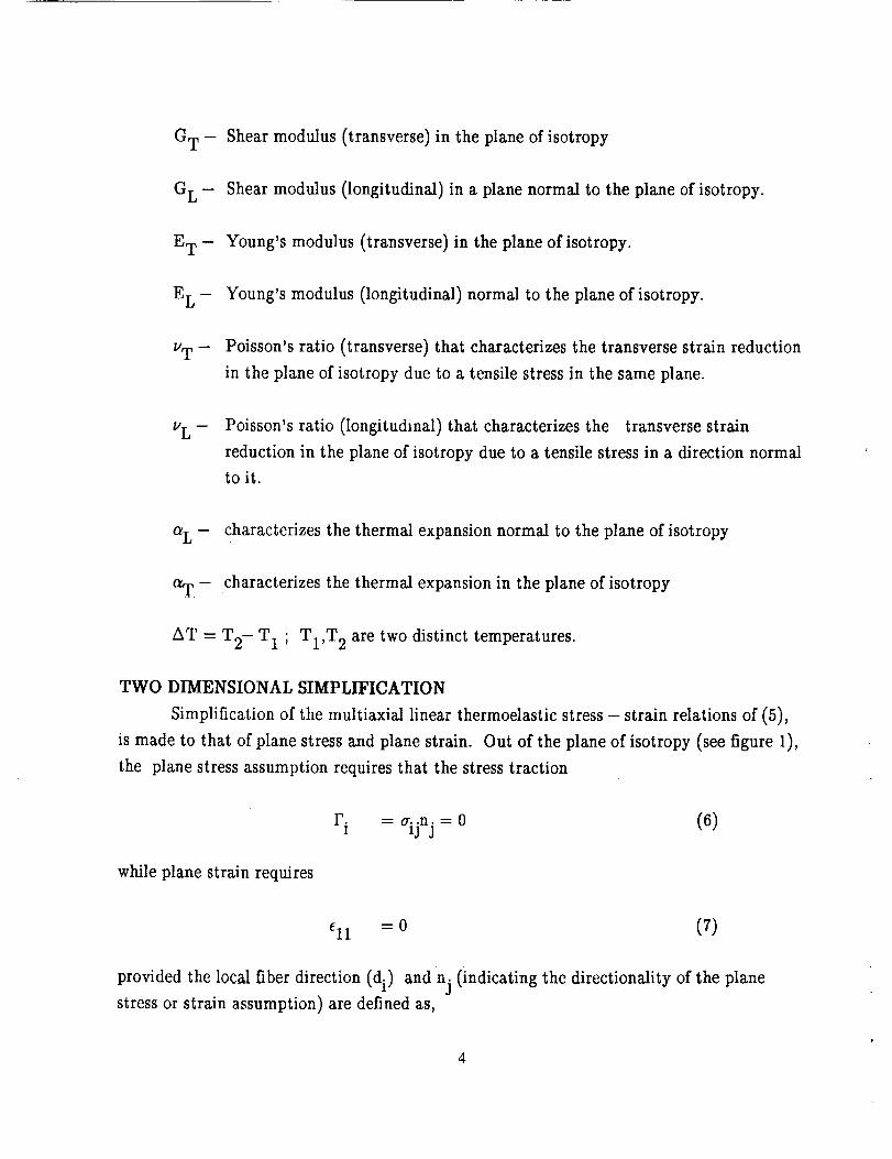
GT - Shear modulus (transverse) in the plane of isotropy
G L - Shear modulus (longitudinal) in a plane normal to the plane of isotropy.
E T " Young's modulus (transverse) in the plane of isotropy.
E L - Young's modulus (longitudinal) normal to the plane of isotropy.
v T - Poisson's ratio (transverse) that characterizes the transverse strain reduction
in the plane of isotropy due to a tensile stress in the same plane.
__Poisson's ratio (longitudinal) that characterizes the transverse strain
reduction in the plane of isotropy due to a tensile stress in a direction normal
to it.
a L - characterizes the thermal expansion normal to the plane of isotropy
o_r - characterizes the thermal expansion in the plane of isotropy
AT = T 2- T 1 ; T1,T 2 are two distinct temperatures.
TWO DIMENSIONAL SIMPLIFICATION
Simplification of the multiaxial linear thermoelastic stress - strain relations of (5),
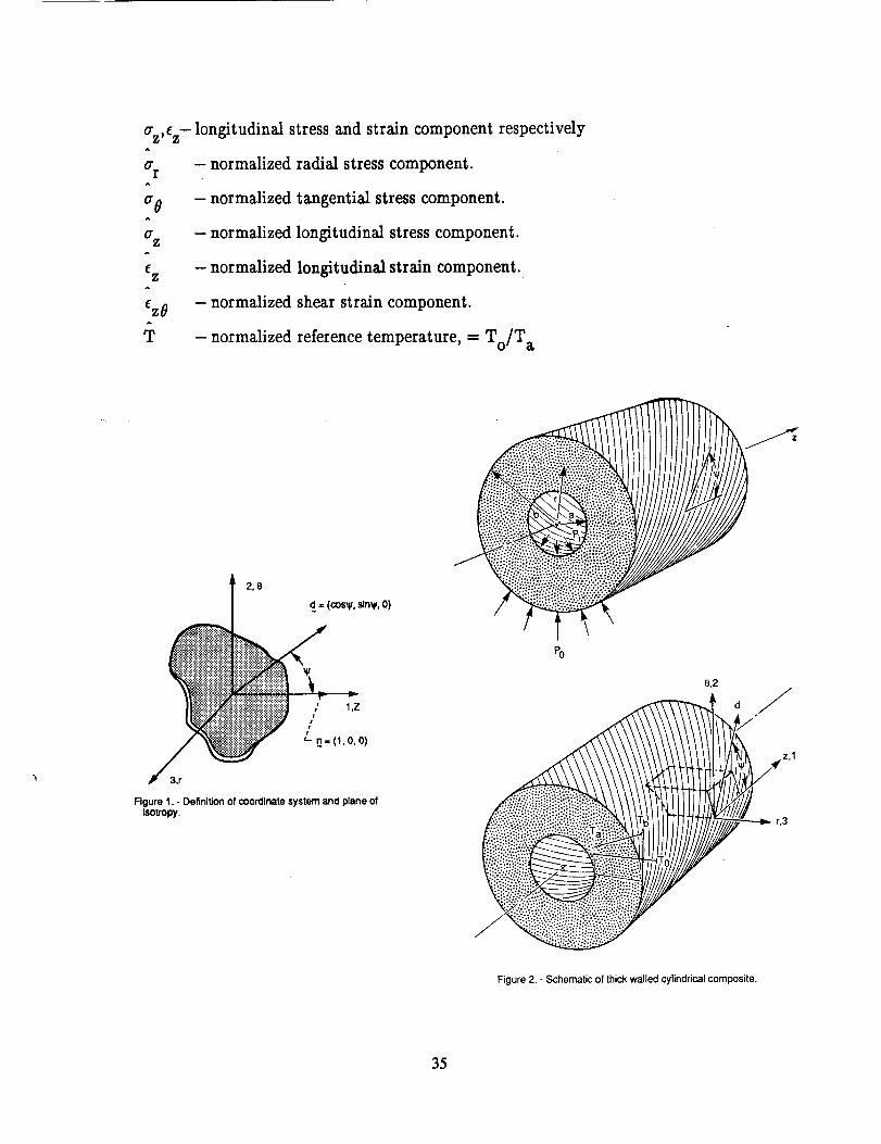
is made to that of plane stress and plane strain. Out of the plane of isotropy (see figure 1),
the plane stress assumption requires that the stress traction
while plane strain requires
r i = aijn j = 0 (6)
=0 (7)
provided the local fiber direction (di) andnj (indicating the directionality of the plane
stress or strain assumption) are defined as,
d1 = cos _ n 1 = 1
d 2 = sin _ n2 = 0
d3 = 0 n 3 = 0
(8)
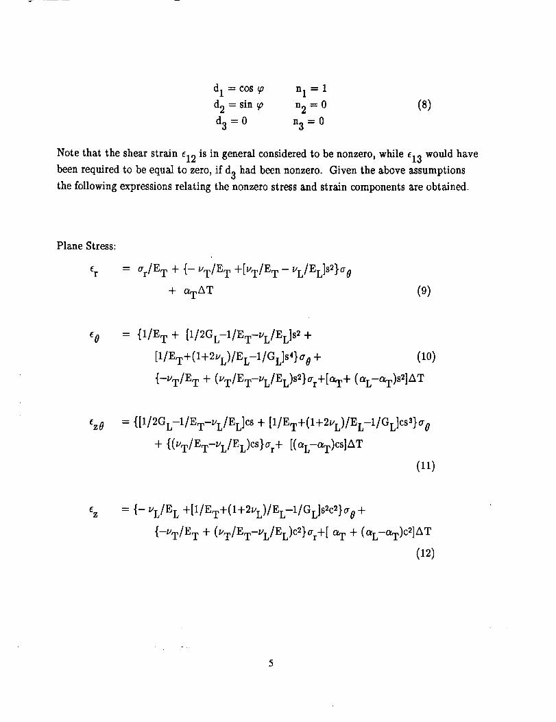
Note that the shear strain el2 is in general considered to be nonzero, while el3 would have
been required to be equal to zero, if d3 had been nonzero. Given the above assumptions
the following expressions relating the nonzero stress and strain components are obtained.
Plane Stress:
er = ar/E T + {-VT/E T +[VT/E T -VL/EL]S2}a O
+ _AT (9)
eo = {1/E T + [1/2GL-1/ET-VL/EL]S_ +
[1/ET+(I+2VL)/EL-1/GL]S4}a 0 + (10)
{-VT/E T + (VT/ET-VL/EL)S2}ar+[aT+ (aL-aT)S2]AT
ez0 = {[1/2GL-1/ET-VL/EL]CS+ [1/ET+(I+2VL)/EL-1/GL]CSS)a0
+ {(vw/Ew-VL/EL)CS}ar+[(aL-C_)cs]AW
(11)
Z = {- vL/EL+[1/ET+(I+2VL)/EL-1/GL]S2C2}a0 +
{-UT/ET + (VT/ET-VL/EL)C2)ar+[aT + (OlL-C_T)C2]AT
(12)
5

Plane Strain:
_r = ar(1/E T ---C2/A} + {-VT/E T +[VT/E T -VL/EL]S2
-CB/A)ao+ {a T ---CD/A} AT (13)
e0 = {1/E T -4- [1/2GL-1/ET-VL/EL]S2 -4-
[1/ET+(I+2uL)/EL-1/GL]S4 -B2/A }a 0
+ {-VT/E T + (VT/ET-VL/EL)S2-BC/A }ar+
[aT+ (aL-aT)s_- BD/A ]AT
(14)
ez0 = ([1/2GL-1/ET-VL/EL](1-B/A)cs +
[1/ET+( I + 2VL)/EL-1/GLI(Cs3 --(B / A )c3s) }a 0
+ {(VT/ET-VL/EL)CS ---C/A([1/2GL-1/ET-UL/EL]CS
+ [1/ET+(I+2vL)/EL-1/GL]C3S)}a r
+ [( aL-aT)cs -(D / A){[1/2GL-1/ET-VL/EL]CS
+[1/ET+(I+2vL)/EL-1/GL]C_S)}]AT
(15)
az = -(B/A)ao-(C/A)ar-(D/A)AT (16)
where A,B,C and D are defined in Appendix A and
sn = sinn_o
n = 1,2,3 and 4
cn = cosn .
ANALYTICAL SOLUTION
The problem under consideration is the solution of a thick walled circular cylinder
with end caps composed of a locally transversely isotropic material (unidirectional
6
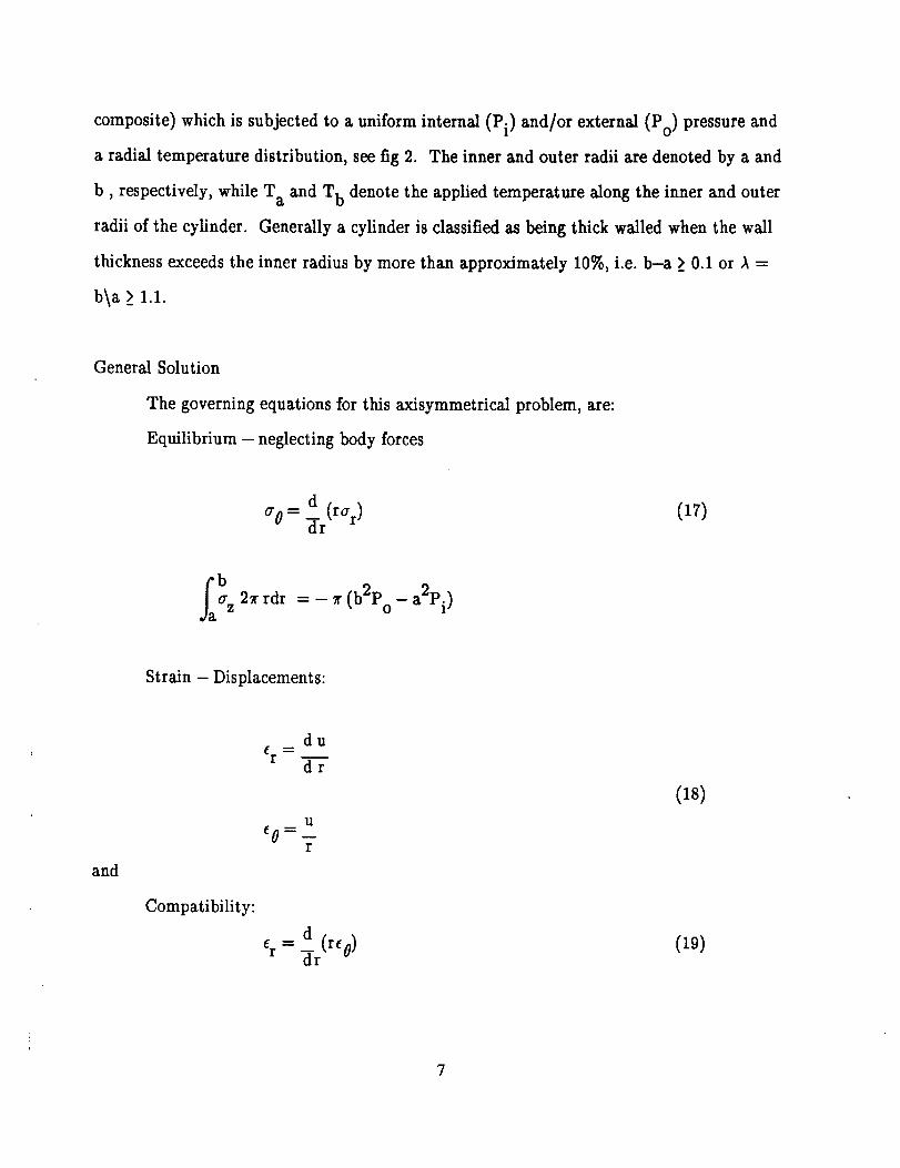
composite) which is subjected to a uniform internal (Pi) and/or external (Po) pressure and
a radial temperature distribution, see fig 2. The inner and outer radii are denoted by a and
b, respectively, while T a and T b denote the applied temperature along the inner and outer
radii of the cylinder. Generally a cylinder is classified as being thick walled when the wall
thickness exceeds the inner radius by more than approximately 10%, i.e. b-a > 0.1 or ,_ =
b\a __1.1.
General Solution
The governing equations for this axisymmetrical problem, are:
Equilibrium - neglecting body forces
aO= dr(rar ) (17)
fab a z 2_r rdr = - _r (b2Po - a2Pi )
Strain - Displacements:
and
Compatibility:
du
_r -- ndr
U
er = dr(reo)
(18)
(19)
7
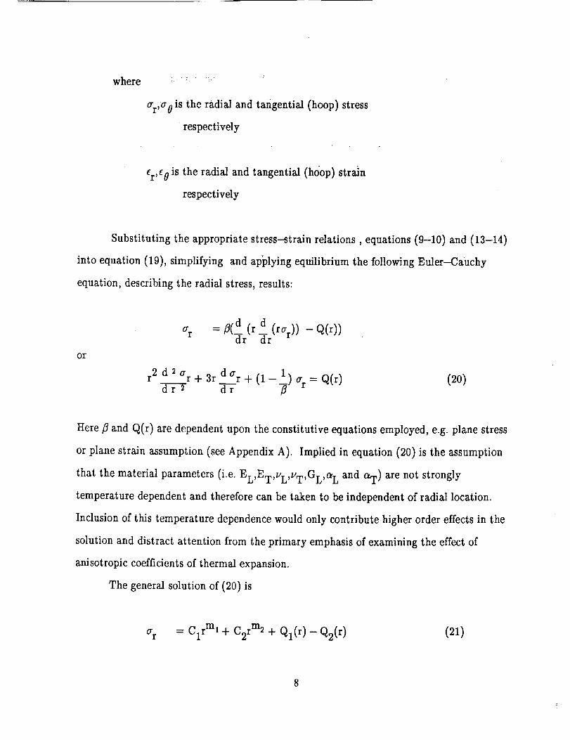
where
ar,a 0 is the radial and tangential (hoop) stress
respectively
er,e 0 is the radial and tangential (hoop) strain
respectively
Substituting the appropriate stress---strain relations, equations (9-10) and (13-14)
into equation (19), simplifying and ap_plying equilibrium the following Euler---Cauchy
equation, describing the radial stress, results:
Or
O"r
r2 d2ar+3r da r+(l_ 1) =d r 2 -_- -_ a r Q(r)
(20)
Here fl and Q(r) are dependent upon the constitutive equations employed, e.g. plane stress
or plane strain assumption (see Appendix A). Implied in equation (20) is the assumption
that the material parameters (i.e. EL,ET,VL,VT,GL,a L and aT) are not strongly
temperature dependent and therefore can be taken to be independent of radial location.
Inclusion of this temperature dependence would only contribute higher order effects in the
solution and distract attention from the primary emphasis of examining the effect of
anisotropic coefficients of thermal expansion.
The general solution of (20) is
ar = clrml + C2r m2 + Ql(r) - Q2(r) (21)
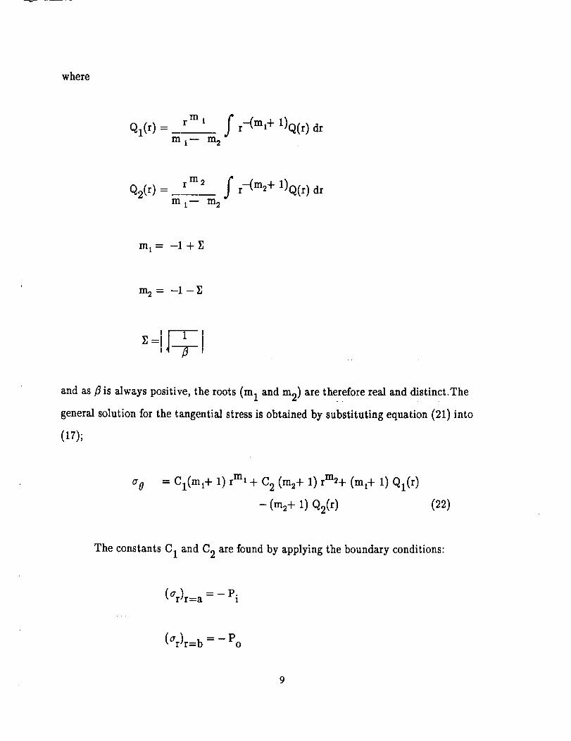
where
rm i f r-(ml% 1)Q(r) drQl(r) -m 1- m2
Q2(r) = rm2 fm 1- m2
r-(m2+ 1)Q(r) dr
m1= --1+ _]
m= = --1--
and as fl is always positive, the roots (m 1 and m2) are therefore real and distinct.The
general solution for the tangential stress is obtained by substituting equation (21) into
(17);
a o = Cl(ml+ 1) rml + C 2 (m2+ 1) rm2+ (ml+ 1) Ql(r)
-(m2+ 1) Q2(r) (22)
The constants C 1 and C 2 are found by applying the boundary conditions:
(ar)r=a = - Pi
(ar)r=b = - Po
9
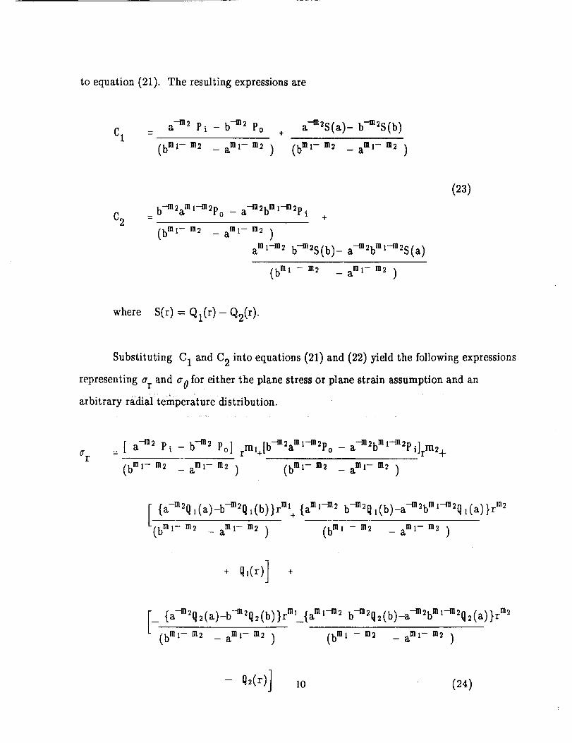
to equation (21). The resulting expressions are
a -m2 Pi - b -m2 Po a--m2S(a) - b-m2S(b)C1 = +
(bml- m2 _ amr m2 ) (bmr m2 _ amr m2 )
C2b-m 2am l--m 2p a-m 2bin _--m2p0 -- i
+
(b rot- m2 - am1- m2 )#
aml-m2 b-m2S(b)_ a-m_bmt-m_S(a)
(bml z m2 _ aml- m2 )
(23)
where S(r) = Ql(r)- Q2(r).
Substituting C 1 and C 2 into equations (21) and (22) yield the following expressions
representing a r and a 0 for either the plane stress or plane strain assumption and an
arbitrary radial:temperaturedistribution.
fir= [ a -m2 Pi - b--m2 Po] rm1+[b-m2aml-m2po
(bml- m2 _ aml- m2 ) (bmt- m2
_ a-m2b m l-m2p i]rm2+
ml- m2-a )
[ {a--m2(t,(a)_b-m2{tl(b)}rm, + {aml--m_ b--m2_{t{t,(b)_a____--m2_bm__il-__2{tl(a)}rm2
(bml- m2 _ aml- m2 ) (bml - m2 _ am i- m2 )
+ q,(r)] +
[__ {a-m2o2(a)-b-m2q2_!b!}rm_{ aml-m2 b-m2q2(b):a--m__22:'_-?_ 2q2(a )}r m2
(bml - m2 _ am1- m2 ) (bml - m2 _ am1- m2 )
(24)

qO(m1+ i)( a-m_ Pi -b -m2 Po} rml
÷
(bml-m_ _ am i- m2 )
(m_+l){b-m2am l-m_po _ a-m_bm l-m2p i}rm__l-
(bmwm_ _ amx -m2 )
(bml- m2 _ aml-m2 ) (bml -m2 _ aml- m2 )
+ q_(r)l(m,+ 1) +
_ {a-m_q_(a)-b-m2q_(b)}rml{am' -m_ b-m_q2(b)_a-m_bml-m2q_(a)}r m_
(bin,-m2 _ am, -m2 ) (b=' -m2 _aml -m, )
- q,(r)1 :1) (25)
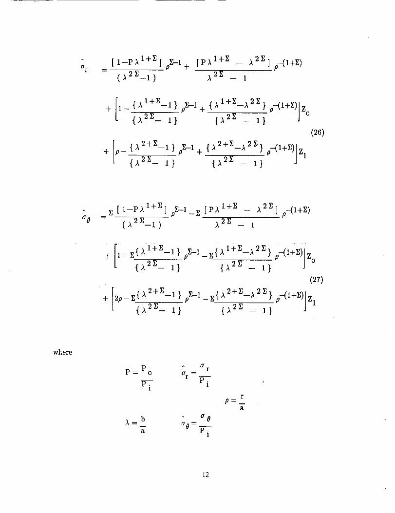
If a linear radial temperature distribution is assumed
AT=Ta-T o+(Tb- Ta) (r-a)-Cb - -aT
and the resulting radial and tangential stress are non-dimensionalized, then the following
expressions are obtained:
11
_v_ere
_ ,oZ.-1---.I )
[Pl I +Z
_ p-(1+z)
+/i_ {I 1+Z
P-(I+_)/Z
_,Z--I+ {_ 2+<2 *-(1+_)/zl (26)
"1)
f1
+_2p-Z{A 2+Z
--Z [Pl l +z
'°"(l+Z)/z 1
°0
I
p_T
a
12
Note £, Z ° and Z 1 are given in Appendix B for the plane stress and plane strain case.
Neglecting all temperature dependence, the above equations can be shown to agree with the
work of Lekhnitskii [2]
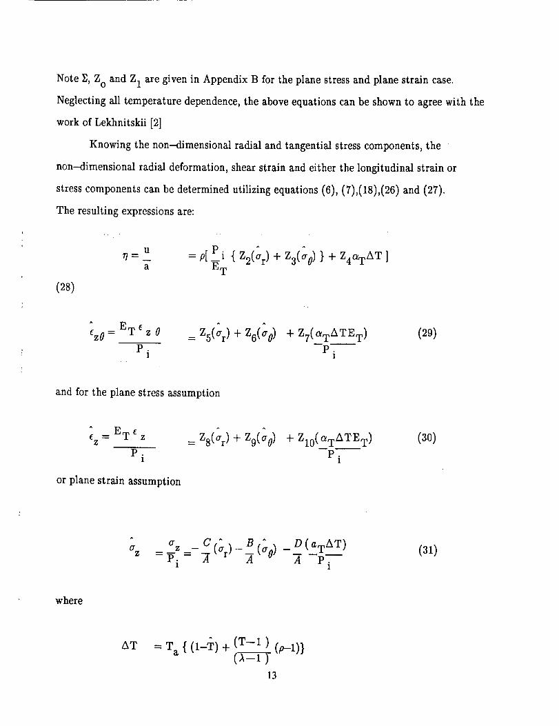
Knowing the non-dimensional radial and tangential stress components, the
non---dimensional radial deformation, shear strain and either the longitudinal strain or
stress components can be determined utilizing equations (6), (7),(18),(26) and (27).
The resulting expressions are:
(28)
UT] ----
a
^ ET eezO= z 0
P ,
1
= p[_P i { Z2(ar) + Z3(a0) } + Z4aTAT]
E T
^ ^
= Zs(_r)+ Zd_0) + Z7( aTATE T)
P.1
(29)
and for the plane stress assumption
^ E TE ---- 6ZZ
P.1
or plane strain assumption
^ ^
=zs(_r)+ z9(_o) + Z10(aTATE T)
p.I
(30)
0"Z %. _ c (<)_, (3o)
-Pi- A "A
_ D(aTAT)
A P.1
(31)
where
AT (T--1) (p -1)}= T a { (1-_?) + (_
13
and
T = Tb/T a
T = To/T a
and A,B, C,D, Z2,Z3,Z4,Z5,Z6,Z7,Z8,Z9,and Zl0 are defined in Appendix B.
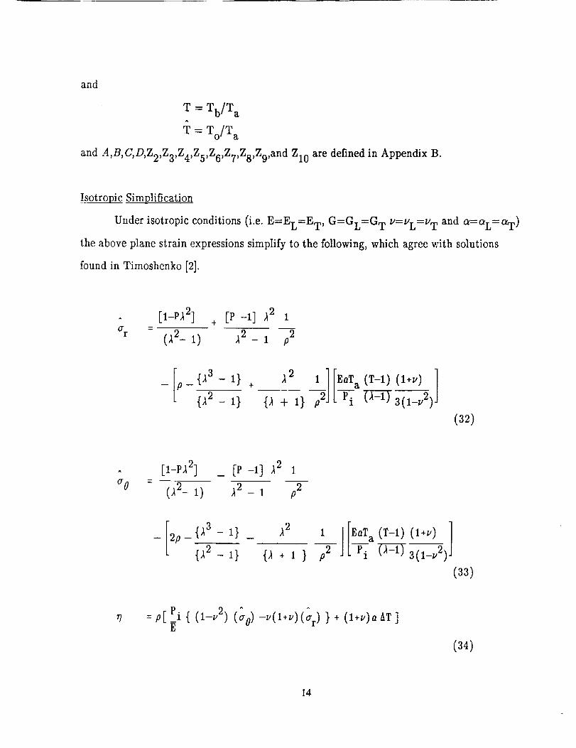
Isotropic
Under isotropic conditions (i.e. E=EL=ET, G=GL=G T V=VL=V T and a=aL=aT)
the above plane strain expressions simplify to the following, which agree with solutions
found in Timoshenko [2].
^ [__pa2] + [p __] a2
- (a2_ _) a2_ _ ;_
_ [;_ {_3_ I} +
L {_2 _}
,12
{_+ i}#2][Z_Ta (r-l) (I+.) l
(32)
a o
[l-P_l 2] _ [P-I] A2 1
(a2_ _) a2_ _ p2
F _ {_3 _ _}
L2_ i_2 i} _2 i ] [EoT_(T-i)(,+.)]
(33)
= p[ _Pi { (l-v 2) (ao) -v(l+v)(_r) } + (l+v)a AT ]E
(34)
14
^
ezO= 0 (35)
+ - (36)
and P,_,p,T and AT are defined as before.
DISCUSSION AND RESULTS
Comparing, in analytical form, the transversely isotropic solution, equations (26)
-(31), to their isotropic counterparts equations (32) -(36), the following general
observations can be made as to the significant role this special anisotropy plays.
1) The shear strain ez0 (eq. 29) is present for an arbitrary angle _o, however
when the material is isotropic or the preferred direction is along the axis of
symmetry (_=0 °) or perpendicular (_=90 °) no shear strain is computed.
2) The radial and tangential stress distribution is at most a function of (1/p 2)
and A2 for an isotropic material, whereas with an anisotropic material
dependence on p and _ is now a function of material properties and
angle of orientation.
3) an isotropic material the longitudinal stress (az) is independentIn of radial
location (p) and equal to a constant when only mechanical loads are present.
Conversely when the material is anisotropic a z is dependent upon material
properties, angle of orientation and p. A similar statement can be made
about the longitudinal strain (ez) when the plane stress assumption is
invoked.
15
4) Considering only thermal loading, no stress is developed under a uniform
temperature field if the material is isotropic. However stresses are developed
in an anisotropic material provided the angle of orientation is not parallel
with the axis of symmetry (_o=0°).
Note similar statements are applicable concerning items 1,2 and 4 when the plane stress
assumption is invoked.
To gain a better understanding of the role anisotropy plays with regard to the stress
distribution; various loading conditions, material parameters and fiber orientations will be
considered. The presentation will be divided into three parts, i) internal/external pressure
loading, ii) thermal loading and iii) thermomechanical loading. All results are presented in
non--dimensional form.
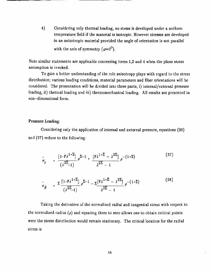
Pressure Loading:
Considering only the application of internal and external pressure, equations (26)
and (27) reduce to the following:
(7r
_ F(l÷r.)_2Z _ 1
(37)
^
(70F, [ I-P'_I*Z] pF-_--1- z[P2I+_]- _2_] p-(l+_)
1
(38)
Taking the derivative of the normalized radial and tangential stress with respect to
the normalized radius (p) and equating them to zero allows one to obtain critical points
were the stress distribution would remain stationary. The critical location for the radial
stress is
16

1
= 2z)]
and for the tangential stress
1
=Pcr (Y_r-1) (1-P,_ 1+_) j
For Pcr to be within the cylinder or disk it must be positive valued and be within
the limits 1<_.Pcr <- )_. Clearly no realistic stationary point is available for the tangential
stress. A realistic stationary point may, however exist for the radial stress distribution as
indicated in (39)depending upon the material parameters, fiber orientation, thickness and
pressure ratio.
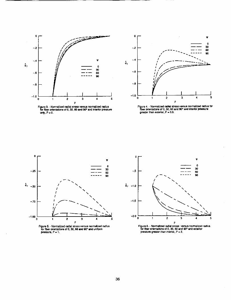
Calculations were performed to illustrate the above dependency on a transversely
isotropic material with the assumed base material parameters listed in Table 1, for four
types of pressure loadings, i.e.;
1) Interior pressure only, P= 0
2) Exterior pressure less than interior, P< 1
3) Equal interior and exterior pressure, P=I
4) Exterior pressure greater than interior, P>I
in figures 3 through 6, respectively. These figures show the effect fiber orientation, i.e. _=
0,30,60 and 90 °, has on the normalized radial stress distribution for a thick walled cylinder
(plane strain assumption), with ratio of outer to inner wall radius ()_) of 5.0.
Observe that when _=0 °, the tiberorientation is aligned parallel with the axis of
'symmetry or equivalently the material is isotropic, i.e. Z=I, thus we find from (39) that
Pcr = ®' therefore no stationary points exist within the cylinder or disk. Thus the
17
maximum/minimum radial stress occurs either at the inner or outer surface, see equation
(37);
and
depending upon the values of the applied pressures. This is consistent with well known
classical solutions [3,4].
For example in figures 3 (P=0) and 4 (P<I) the maximum stress occurs at the inner
surface, while in figure 5 (P=I) it is constant and in figure 6 (P>I) the maximum stress
occurs along the outer surface. Clearly the development of stationary points within the
cylinder is dependent upon orientation and loading. Case in point is observed in figure 4,
were for _o=60 and 90°the radial stress actually becomes less than the applied exterior
pressure, which utilizing isotropic intuition should be the minimum stress obtainable.
Conversely, the maximum stress continues to remain either at the interior or exterior
surface independent of orientation, as one might expect since the stress component is
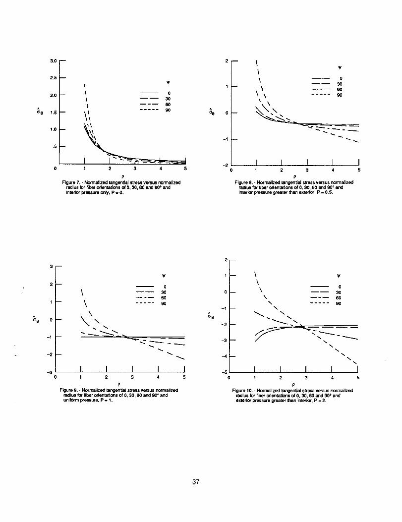
governed by boundary conditions, i.e. the type of loading. The corresponding tangential
stress distribution is shown in figures 7-10 respectively, for P=0, P<I, P=I and P>I and
as indicated by (40) no stationary points are observed regardless of fiber orientation.
Work with isotropic thick walled cylinders [4] has shown that when both internal
and external pressure act simultaneously the location of the maximum tangential stress, be
it along the inner or outer surfaces, is dependent upon both geometry and the ratio of
external to internal pressure. This conclusion is supported by the present work, figures
7-10, with the additional dependency of material property and fiber orientation due to the
anisotropy of the material. This is evident in the following equation which expresses the
18
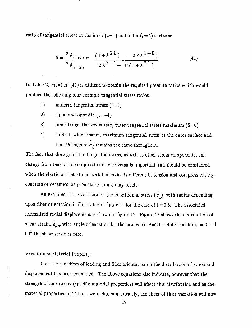
ratio of tangential stressat the inner (#=1) and outer (p=_) surfaces:
a0. (1+,_ 2P') _ 2p)_ l+y_)S = 1nner =
at?oute r 2,_ y_-I- p(l+)_ 2I])
(41)
In Table 2, equation (41) is utilized to obtain the required pressure ratios which would
produce the following four example tangential stress ratios;
1) uniform tangential stress (S=l)
2) equal and opposite (S=-l)
3) inner tangential stress zero, outer tangential stress maximum (S=0)
4) 0<S<I, which insures maximum tangential stress at the outer surface and
that the sign of a 0 remains the same throughout.
The fact that the sign of the tangential stress, as well as other stress components, can
change from tension to compression or vice versa is important and should be considered
when the elastic or inelastic material behavior is different in tension and compression, e.g.
concrete or ceramics, as premature failure may result.
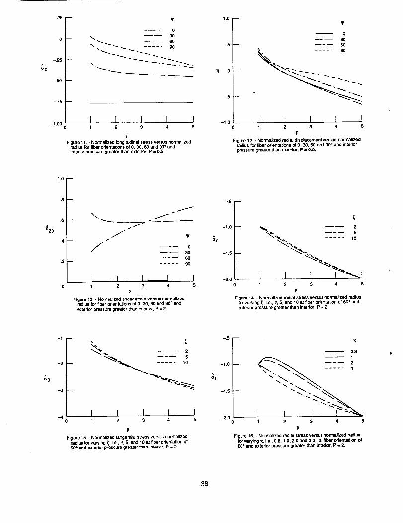
An example of the variation of the longitudinal stress (a) with radius depending
upon fiber orientation is illustrated in figure 11 for the case of P=0.5. The associated
normalized radial displacement is shown in figure 12. Figure 13 shows the distribution of
shear strain, ez0 , with angle orientation for the case when P=2.0. Note that for _o = 0 and
90 ° the shear strain is zero.
Variation of Material Property:
Thus far the effect of loading and fiber orientation on the distribution of stress and
displacement has been examined. The above equations also indicate, however that the
strength of anisotropy (specific material properties) will affect this distribution and as the
material properties in Table 1 were chosen arbitrarily, the effect of their variation will now
19
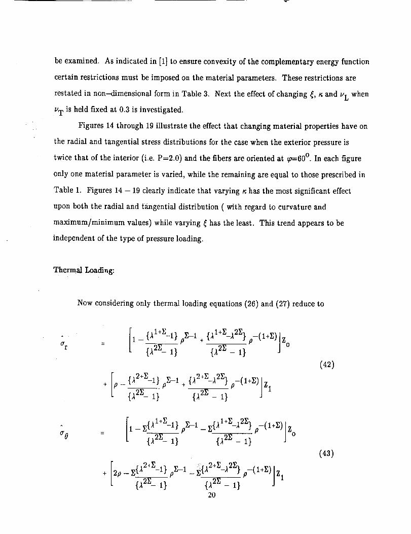
beexamined. As indicated in [1] to ensure convexity of the complementary energy function
certain restrictions must be imposed on the material parameters. These restrictions are
restated in non---dimensional form in Table 3. Next the effect of changing _, _; and u L when
uT is held fixed at 0.3 is investigated.
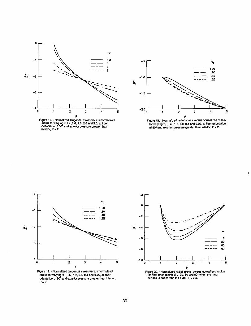
Figures 14 through 19 illustrate the effect that changing material properties have on
the radial and tangential stress distributions for the case when the exterior pressure is
twice that of the interior (i.e. P=2.0) and the fibers are oriented at _a=60 °. In each figure
only one material parameter is varied, while the remaining are equal to those prescribed in
Table 1. Figures 14 - 19 clearly indicate that varying _; has the most significant effect
upon both the radial and tangential distribution ( with regard to curvature and
maximum/minimum values) while varying _ has the least. This trend appears to be
independent of the type of pressure loading.
Thermal Loading:
Now considering only thermal loading equations (26) and (27) reduce to
ar = 1 {_2r__ 1}
^
a 0
+
+ p_(l+r )lz1
_, l+r..2r_}[1- Z{_l+_-l} pT_,--1 _ Zl,4 -,_ p-(i+r,)] Zo
2O
(42)
(43)
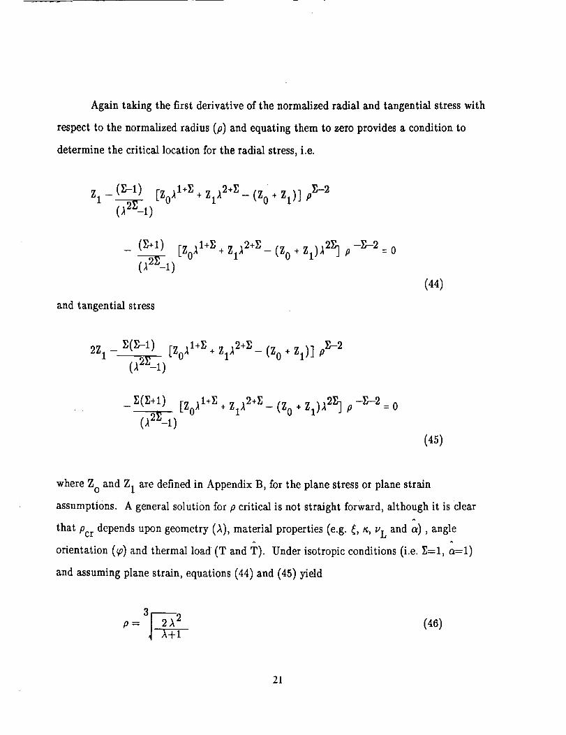
Again taking the first derivative of the normalized radial and tangential stress with
respect to the normalized radius (p) and equating them to zero provides a condition to
determine the critical location for the radial stress, i.e.
zl - (r,-1) [Zo_l+r,+Zl_2+__(Zo+zl)] pZ--2
and tangential stress
1+_ +zd2+s_(Zo+z_)_2z]p-Z-2 o
(44)
1+_ + Z1,12+$ - (Z 0 + Zl)] pTr-2
i+_ +zd2+r,_(Zo÷z_)?.z]p-r,-2 o
(45)
where Z° and Z 1 are defined in Appendix B, for the plane stress or plane strain
assumptions. A general solution for p critical is not straight forward, although it is clear
that Pcr depends upon geometry (A), material properties (e.g. _, to, u L and _), angle
orientation (_v) and thermal load (W and 'r). Under isotropic conditions (i.e. Z=I, a=l)
and assuming plane strain, equations (44) and (45) yield
P = 3/r 2 A2 (46)
21

.=3[ (47)
respectively. Clearly no stationary point exists for the tangential stress, as p would be
imaginary. The radial stress may, however have a stationary point depending of course
upon the ratio _.
Calculations were performed to investigate the above dependency for the
transversely isotropic base material of Table 1, when
1) inner surface is hotter than the outer surface (T<I)
2) uniform temperature field (T=I)
3) outer surface is hotter than the inner surface (T>I).
For simplicity the temperature at the inner surface (Ta) is assumed to be equal to the^
reference temperature (To) , i.e. T = 1, except for case 2 (T=I) as both Z 0 and Z 1 would^
be equal to zero and no temperature loading would exist if T = 1.
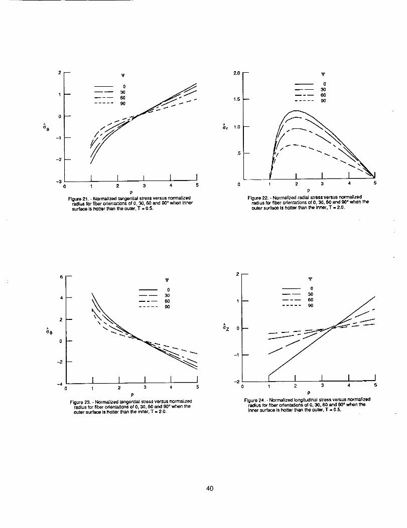
Figures 20 -23 show the radial and tangential stress distributions through the
thickness of the cylinder at 30 ° increments in fiber orientations, for thermal loadings of T
< 1 and T > 1 respectively. Clearly the sign for both the maximum radial and tangential
stress (be it tensile or compressive) is dictated by the type of loading (i.e. T <1 or T>I)^
for a fixed T. Also the location of the maximum radial stress is now angle and material
dependent sincc the radial stress at the inner and outer surface are zero. The maximum
tangential stress occurs at the inner surface independent of angle and thermal loading.
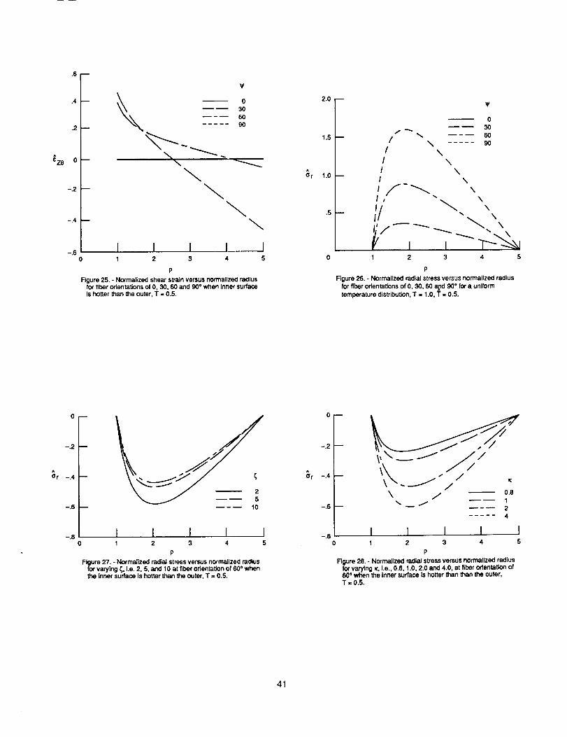
The variation with radius for a z and ez8 are given in figures 24 and 25 for load case
1 (T<I). As one would expect a z varies linearly with p at a 0 ° fiber orientation and the^
normalized shear strain (ez0) is zero. A non--zero shear strain and a nonlinear distribution^
of a z is observed for off-axis orientations and (as with pressure loadings) the magnitude is
highly dependent upon material properties, thickness ()_) and angle.
22

The radial stressdistribution producedfor a givenfiber orientation under auniform
temperature iT=l) distribution is shownin figure 26. No radial (or tangential) stressis^
calculated for a 0° orientation as one would expect since both a r and a 0 are in the plane of
isotropy. Note that the sign (tensile or compressive) of the stress (radial or tangential) is
dependent upon whether the applied thermal load is above (T<I) or below (_?>1) the^
reference temperature. In figure 26, T is equal to 0.5. It is important to realize that both
expansion and contraction could take place within the thickness of the cylinder if both T^
and T are less than or greater than one, but not equal.
Variation of Material Properties:
The effect of varying material property parameters, when the cylinder is subjected
to a thermal load is very similar to that shown for the pressure loadings. For example in
figures 27 and 28 the effect on the radial stress distribution of changing _, (i.e. _=2,5 and^
10) and _ (i.e. _; = 0.8,1.0,2.0 and 4.0) are shown respectively for the case when T=0.5, T
= 1.0, o_=0.5 and at a fiber angle of 60 °, see figure 20. In addition to varying these
mechanical material parameters, the coefficient of thermal expansion will play a significant
role in two ways.
The first is its effect on the sign of the stress; for example if o_=O_L/O_T>l (cf. figure^ ^ ^ ^
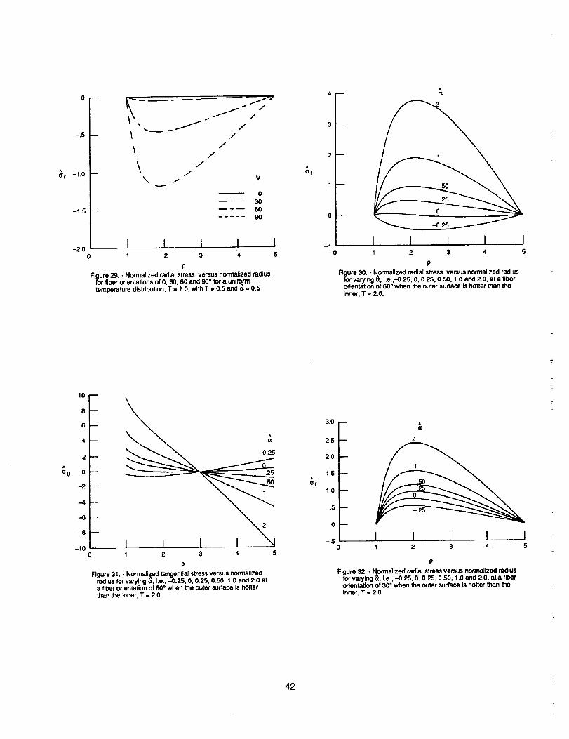
26 where o_=2.0 and 'r<l) a r is tensile whereas if oe<l (cf. figure 29 where oL=0.5 and T<I^
and T=I) o"r is compressive. The second is in the actual magnitude and how it affects the
magnitude of the various stress components as illustrated in figures 30 and 31 where arand^ ^
a 0 versus p are displayed respectively. For the case when T=2.0, T=I, _o= 60 ° and oe =^
-0.25,0.0,0.25,0.5,1.0 and 2.0. Figure 30 and 31 clearly indicate that as oe approaches zero
a minimum radial and tangential stress state is reached. This a value, which produces a
minimum stress state is not uniq_ as it is highly fiber orientation dependent. Examples of
this are shown in figures 32 and 33 for the identical case shown in figure 30 but with the
angle _ being changed to 30 and 90 ° respectively.
23
A
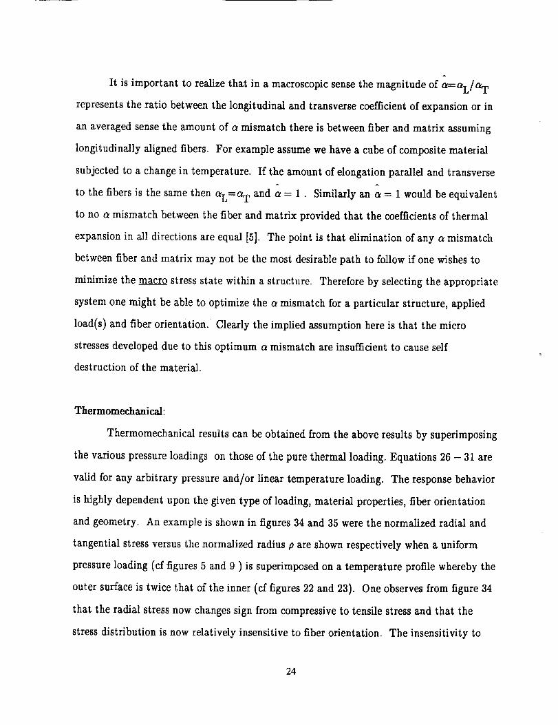
It is important to realize that in a macroscopic sense the magnitude of a=-aL/a T
represents the ratio between the longitudinal and transverse coefficient of expansion or in
an averaged sense the amount of a mismatch there is between fiber and matrix assuming
longitudinally aligned fibers. For example assume we have a cube of composite material
subjected to a change in temperature. If the amount of elongation parallel and transverse
to the fibers is the same then O_L=OLT and a = 1. Similarly an a = 1 would be equivalent
to no a mismatch between the fiber and matrix provided that the coefficients of thermal
expansion in all directions are equal [5]. The point is that elimination of any a mismatch
between fiber and matrix may not be the most desirable path to follow if one wishes to
minimize the macro stress state within a structure. Therefore by selecting the appropriate
system one might be able to optimize the a mismatch for a particular structure, applied
load(s) and fiber orientation. Clearly the implied assumption here is that the micro
stresses developed due to this optimum _ mismatch are insufficient to cause self
destruction of the material.
Thermomechanical:
Thermomechanical results can be obtained from the above results by superimposing
the various pressure loadings on those of the pure thermal loading. Equations 26 - 31 are
valid for any arbitrary pressure and/or linear temperature loading. The response behavior
is highly dependent upon the given type of loading, material properties, fiber orientation
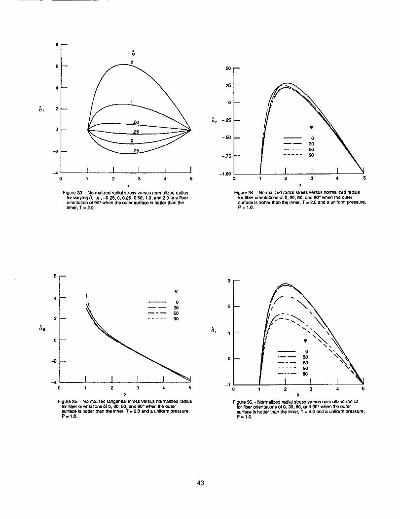
and geometry. An example is shown in figures 34 and 35 were the normalized radial and
tangential stress versus the normalized radius p are shown respectively when a uniform
pressure loading (cf figures 5 and 9 ) is superimposed on a temperature profile whereby the
outer surface is twice that of the inner (cf figures 22 and 23). One observes from figure 34
that the radial stress now changes sign from compressive to tensile stress and that the
stress distribution is now relatively insensitive to fiber orientation. The insensitivity to
24
orientation is merely a coincidence as clearly shown in figure 36 where the temperature at
the outer surface is now four times that of the inner.
CONCLUSIONS:
A continuum theory representing the thermoelastic behavior of unidirectional
composites has been applied to the problem of a thick walled cylindrical tube subjected to
internal and external pressure and a radial temperature distribution. The resulting
analytical solution was then specialized for a linear radial temperature distribution and was
expressed in non---dimensional form. A limited parametric study was conducted in which
four types of pressure loadings and three types of radial temperature profiles were
examined to develop intuition with regard to the effects of transverse isotropy.
This analytical solution provides a benchmark problem for structural analysis code
verification and may be employed to illustrate the stress, strain and deformation
distributions within a unidirectional tubular composite test specimen or the thrust
chambers of reusable rocket engines. The results clearly illustrate that the stress and strain
response is highly dependent upon geometry, fiber orientation, material properties and type
of loading. Finally it was illustrated that to minimize the macro stress or strain state
within this structure subjected to the given pressure and thermal loadings a non unique a
mismatch would be desired. This mismatch is highly dependent upon fiber orientation,
material property and geometry.
REFERENCES
1) Arnold, S.M., "A Transversely Isotropic Thermoelastic Theory", NASA
TM101302, Aug 1988.
2) Lekhnitskii, S.G., Theory of Elasticity of an Anisotropic Body, Holden-Day,
San Francisco,pp. 44,45 and 249-252, 1963.
25
3)
4)
5)
Timoshenko, S.P. and Goodier, J.N., Theory of Elasticity, McGraw-Hill,
New York, pp 441-451, 1970.
Ugural, A.C. and Fenster, S.K., Advanced Strength and Applied Elasticity,
Elsevier, New York, pp 246-253, 1975.
Hashin, Z., "Analysis of Composite Materials - A Survey", Jill. of Appl.
Mech., Vol 50, pp 481-505, 1983.
26

APPENDIX A
Material dependentparametersof the Euler---CauchyEquation.
Plane Stress(utilizing equations(6))
1 + ( 1 _ 2 _ 2_L)s2 +( 1 +(1+2vL)_ 1L)s4}_: ET{ ET gL _T EL ET EL
{](r) :-ET{ (aL-aT)s2 AT + (a T + (aL-aT)S 2) rd--drAT)
Plane strain ( utilizing equations (7))
_-{ 1 + ( _i _2 __2VL)s2+ ( _I + (l+2UL)_ I )s4 - B2 }
ET GL ET EL ET EL GL
t _ET ]
' ' dhTq(r) = _1/iT + _2 r_
dr
where
-[(aL-aT)S 2 + (C - B)D ]
A
1+
_T
1 2 2VL)s2 + ( 1 + (1+2VL)_ 1 )s4 B2
(GL ET EL ET _ UL -][ }
27

/32=
-[a T + (a L - aT)S 2 - BD ]
I-
1+
ET( 1 _ 2 _ 2VL)s2 + ( _1 +
UL ET EL ET
- _ - B2(l+2UL) 1 )s 4 }
EL GL _[
and
1 + ( 1 2 _2UL)c2
( ET GL ET EL
+ (_1 + (l+2v L)__I )c 4}
ET EL GL
= { vL_ + (_1 + (l+2VL)1 )s2c 2}
EL ET EL _L
= {-_T + (_VT-VL)c 2}
ET ET EL
= [a T+ (a L-a T)c 2]
AT --T(r) -T0
S n
C n
= sin n _o
= COS n _0
n = 2,4
28
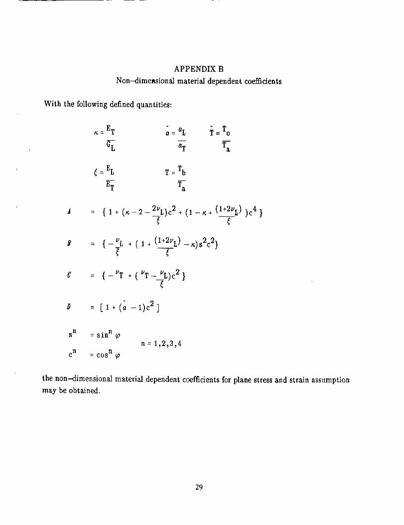
APPENDIX B
Non-dimetsional material dependentcoefficients
With the following definedquantities:
a ET ^ aL---- Q=
^
T = To
Ta
= EL T = Tb
ET Ta
A (l+2v L) c 4,[ 1 + (_-2-2VL)c2+__ (l-a+ ) )
{-_L +(I+ (I+2_L)-_)_2c2)
C
D
{-v T + (VT-V L)c 2}
[i+ (_- 1)c2]
sn = sin n _o
Cn = COS n _O
n : 1,2,3,4
the non---dimensional material dependent coefficients for plane stress and strain assumption
may be obtained.
29

Plane stress (utilizing equations (6))
/_ = {1
Z o
Z 1
Z2
Z3
Z4
Z5
Z6
Z7
Z8
Z9
I]2= 1//_
+ (_-2-2_L).J + (1 + (1+2_L)- _)s4 }
=-ETaTTa [ (a- 1)s 2 ] [ (3-T) -T ]
Pi( _ - 1 )
=-ETaTTa [1 +2(_- 1)s2 ] (T-I)
Pi(4Z- 1 ) _U
= (v T-VL)s 2-v T
T
=
= i+(_-i)s2
= (K_-I-_VL)cs + (i + (l+2VL) -_;)cs3
Zlo
=(Li)_s ",
= -v T + (vT- _L)c2
=-'L+(i+(i+ 2,L)__)s22
= 1+ (_-l)c 23O
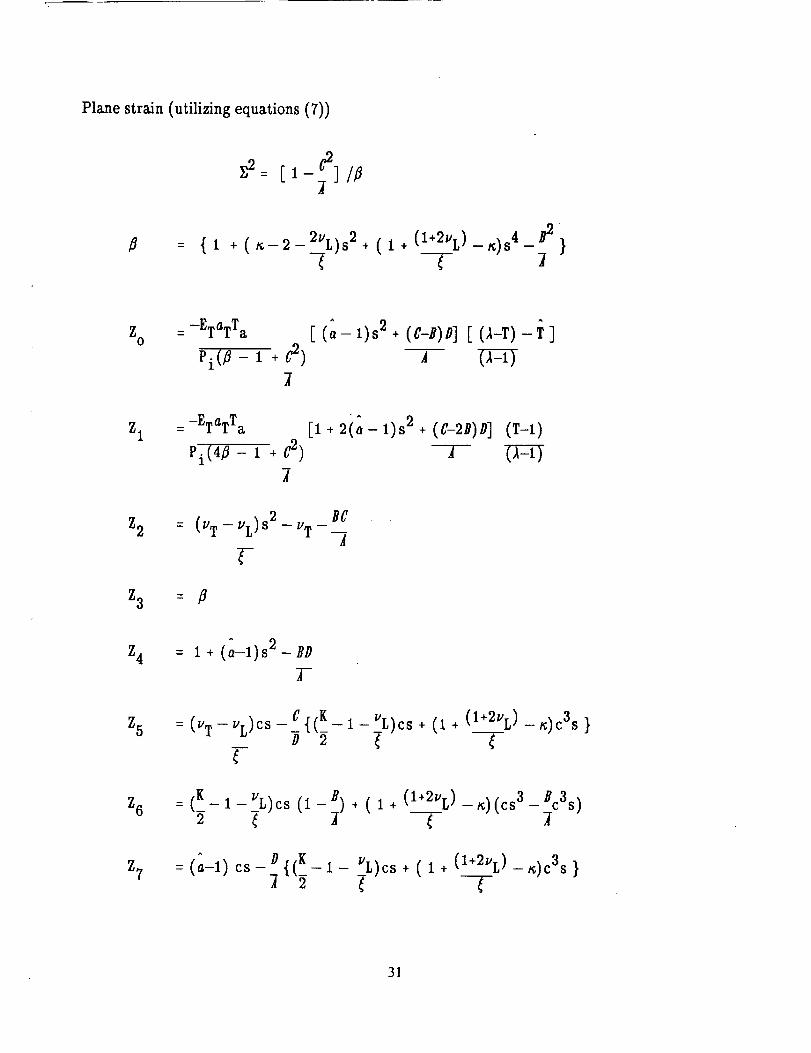
Plane strain (utilizing equations(7))
B {i +(_-2-2%)_2+(I+(I÷2"L)-_)_4__
Z0
= -ETaTTa
Pi(_ - i + C2)
^
[ (,,- I)s2+ (c-n)D][ (,_-T)-_ ]A
Z1= -ETaTT a
Pi(4_- I + C2)
[i +2ia-l)s2+ (C-2B)D](T-I)TZ:U
Z2 = (VT-VL)S2-UT BC--_
Z3 =
Z4 : i + ---(a-1)s2- BDT
Z5 : ("T - VL)CS - C ,[(K_D 2
T-
I-_L)cs + (I + (I+2VL)-_)c3s }
Z6 = (K-I-_UL)cs(l-B)+ (1+ (I+2UL)-_;)(cs3-Bc3s)
Z7: (a-l) cs-Di{(K2 I- __L)cs
+ ( 1 + (I+2UL)-_)c3s }
-7-
31

TABLE 1
Base Material Parameters
E T = 15000 ksi
% = 0.8v T = 0.3
aT = 3"0x10"-6a=0.5
TABLE 2
Required Pressure Ratio to Produce the Circumferential Stress Ratio
S = --1p
S-0p
S=I
O<S<l
p ___
<P<2,1y-'--1 - 1 - ,12y"
1 + j2Y__ 2jII+E
32
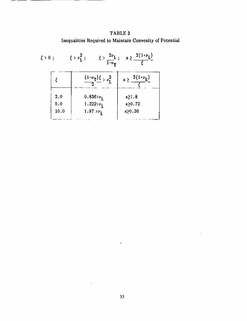
TABLE 3
Inequalities Required to Maintain Convexity of Potential
_>0; > v_ ; _> 2vI,; _;> 2(l+VL)
1-v T
(1-VT) _ > v[2
2.0 0.836>v L
5.0 1.322>v L
10.0 1.87 >v L
......... J ................
> 2(l+v L)
_1.8
_>0.72
_>0.36
33
NOMENCLATURE
fl - ComplementaryEnergy Function
di - Vector denotinglocal fiber direction
eij - total infinitestimal strain tensor
aij - Cauchy stress tensor
T - Temperature
Pk - Physical Invariants k=1,2,3,4,5
Ik - Invariants k=1,2,4,5
G T - Transverse shear modulus
G L - Longitudinal shear modulus
E T - Transverse Young's modulus
E L - Longitudinal Young's modulus
_'T - Transverse poisson's ratio
_'L -Longitudinal Poisson's ratio
a L - Longitudinal thermal expansion
a T - Transverse thermal expansion
a - normalized thermal expansion coefficient, aLia T
F. - Stress traction vector
_o - Angle between axes 1 and 2 or z and 0.
Pi - Internal pressure
Po - External pressure
P - Normalized pressure, i.e Pi/Po.
a -inner wall radius
b - outer wall radius
T a - temperature at inner wall
T b - temperature at outer wall
T - ratio of temperature of outer wall to that of inner.
._ - ratio of outer wall radius to that of inner.
u - radial displacement
77 -normalized radial displacement, =u/a
r - radial location
p -normalized radial location, = r/a
ar,e r- radial stress and strain component respectively.
_r0,e_--tangential stress and strain component respectively.
34
az,e z- longitudinal stress and strain component respectively^
a 0^
%
EZ
ez 0^
T
- normalized radial stress component.
- normalized tangential stress component.
- normalized longitudinal stress component.
- normalized longitudinal strain component.
- normalized shear strain component.
- normalized reference temperature, = To/T a
i _ _iii!_/llllllll//I/I///////J
2, e _ ' :!:':'i:'..::.'::::":_ ::':.::':':::'-.::.'.."..:"_:
(cos¥,sln¥,O)
======================= y
I,ZI__._ ,'
......i_ii:_.'L._.!:i.,.:ii:i:_:_:i::%"_.' /
-,_.,,.o.o,• 3,r
Rgure 1. -Definition of ooordlnate system and plane ofIsotropy.
Figure 2. - Schematic of thick walled cylindrical composite.
35
_.2 ,,__/
^ -.4 _- i/,_ f ¥
°' L !,/--.8
-1.o I I0 1 2 3 4 5
P
Figure 3.- NormaJlzed radlaJstress versus normalized racllusfor fiber orlenlalJons of O, 30, 60 and 90 ° and Intedor pressureone/.P-o.
-,2
-.4A
Or
-.6
-.8
-1.0
¥
0
m 30
- //__
i L i t i2 3 4 5
P
Figure 4. - Normalized radial stress versus r_orrnallzed radius forfiber oden;ations of O, 30, 60 and 90" and Interior wessure
greater than exterior, P - 0.5.
-.25
_r -.50
-.75
-1.000
03O
6O..... 90
I/ _,
I _--_ \\
1 2 3 4 5
P
Figure 5. - Normalized radial s_ess versus normalized racllusfor fiber orientations of O,30, 60 and 90 a and uniformpressure, P- 1.
Or
-.5
-1.0
-1.5 m
-2.00
¥
o3O
60
/_._. ..... 90
/ \
_ "
1 2 3 4 5
P
Figure 6. - Normalized radial stress versus normalized radiusfor fiber orientations of 0, 30, 60 and 90° and exteriorIxessure Greater than interior, P - 2.
36
_e
3,0 m
2.5
2.0
1.5
1.0
I ¥
I ot 3O
l 6O
\l l ..... 9o
I 2 3 4 5
P
Figure 7. - Normalized tangential stress versus normalizedradius for fiber odentatlons of O, 30, 60 and 90 ° andInterlor pressure only, P. O.
2 --
I --
0 --
-20
lo
3o\ 6o
\\ ..... 9o
I I I ,I1 2 3 4
P
Figure 8. - Normalized tangential s_'ess versus normalizedradius for fiber orientations of 0, 30, 60 and 90° andinterior pressure greater _ exterior. P - 0.5.
^
3 --
2 --
1 --
0 --
-2 --
-30
\\
\
\\
¥
03o
6o
I I I I I1 2 3 4 5
P
Figure 9. - Normalized tangential sVess versus normalizedradius for fiber odentetlons of 0, 30, 60 and 90o anduniform pressure, P = 1.
^
(;o
2 --
1 --
0 --
-3 --
-4 --
-5
¥\\
0\ 3o
\ 6o
% ..... 90\
%.
I I I I1 2 3 4
P
Figure 10. - Normalized tangential stress versus normalizedradius for fiber orlentatlons of 0, 30, 60 and 90 ° andexterior pressure greater than Interior, P - 2.
I
37
.25v/ 1.0
^
o z
-.25
-.50
-.75
0 m
m
-1.000
o
30
\, ---... ..... 90
I , I .... I I I1 2 3 4 5
P
Figure 11. - Normalized longitudinal stress versus normalizedradius for fiber orlenta_ons of 0, 30, 60 and 90 ° andInterior pressura greater than exterior, P = 0.5.
.5
"q 0
-.5
-1.0
03O
6O
..... 90
I I I ] I0 1 2 3 4 5
P
Figure 12. - Normalized radial displacement versus normalizedradius for fiber orien_Eions of 0, 30, 60 and 90° and |nterlorpressure greater than exterior, P - 0.5.
1.0
^
SZ@
.8 m
\ /
/i
/
7
¥
o
3060
90
I I I I1 2 3 4
P
Figure 13. - Normaffzed shear strain versus normalizedradius for fiber orientations of 0, 30, 60 and 90 ° andexterior pressure greater than Interior, P = 2.
^
Cr r
-1.0
-1.5
-2.00
- ..... ,!
1 2 3 4 5
P
Figure 14. - Normalized radial stress versus normalized radius
for varying _, I.e, 2, 5, and 10 at fiber orientation of 60" andexterior pressure greater than Interior, P = 2.
-1
-2
-3
-40
2-- 10
I 1 1 I1 2 3 4
P
Figure 15. - Normalized tangential stress versus normalizedradius for varying 4, I.e., 2, 5, and 10 at fiber orientation of60 ° and exterior pressure greater than Interior, P - 2.
_'r
-.5 m
-2.00
0.8
2
\ • ..... 3
I I I I" _--_11 2 3 4 5
P
Figure 16. - Normalized radial sVess versus normalized radiusfor varying _, I.e., 0.8, 1.0, 2.0 and 3.0, at fiber odentatlion of60 ° and exter/or pressure greater than intedor, P. 2.
38
_e
0 --
-1 --
-2 --
-3 --
-40
K
08
I I I I1 2 3 4
P
Figure 17. - Normalized tangenlJal stress versus normalizedradius for varying _ I.e.,O.8, 1.0, 2.0 and 3.0, at fiberorlentaUon of 60 ° and extedor pressure greater thanInlerlor, P = 2.
I5
Or
-.5
-1.0
-1.5 --
-2.00
_L
1.20
.80
.40
-- _ ..... +25
I 2 3 4 5
P
Figure 18. - Normalized radlal stress versus normalized radius
for varylng _oL, Le., 1.2, 0.8, 0.4 and 0.25, at fiber orientatlonof 600 and extedor pressure greater than interior, P - 2.
o6
0 --
-1
-2
-40
_L
I I I I II 2 3 4 5
Figure lg. - Normalized tangential stress versus normalized
radius for varying o L, I.e., 1.2, 0.8, 0.4 and 0.25, at fiberorientation of 60 ° and exterior pressure greater than Interior,P=2.
0
A
o r -.4
-.8
-1.0
3O
6O
I 1 I I I0 1 2 3 4 5
P
Figure 20. - Normalized radial stress versus nocmallzed radiusfor fiber orientations of 0, 30, 60 and 90 ° when the innersurface is hotter than the outer, T = 0.5.
39
^
a e
2
0
-30
¥
o
jl _,,r
jI I I 1 I1 2 3 4 5
P
Figure 2"_. - NormaJJzed tangental stress versus normaJJzedradius for fiber orientations of 0, 30, 60 and 90° when innersurface is hotter than the outer, T = 0.5.
^
2.0
1.5
1.0 --
.5 --
o30
6ow .... 90
1 2 3 4 5
P
Figure 22. - No:realized radial s_ress versus normatlzedradius for fiber orientations of 0, 30, 60 and 90 =when theouter surface is hotter than the Inner, T - 2.0,
^
o0
6
4
2
0
-2 --
-40
0
--- 6o
I 1 I I1 2 3 4
P
Figure 23. - Normalized tangential stress versus normalizedradius for fiber odenta_ons of O, 30, 60 and 90° when theouter surface is hotter than the inner, T = 2.0.
_Z
-2
0
3o
I I I I I1 2 3 4 5
P
Figure 24. - Normalized longitudinal sb'ess versus normalizedradius for fiber orientations of 0, 30, 60 and 6O* when theInner surface is hotter than the outer, T = 0.5.
4O
^
eZ0
.6 m
.4 m
0 m
-.2
-.4
o
3O
6o..... gO
\\
\\
I I I I0 1 2 3 4
P
Figure 25. - Normalized shear strain versus normalized radiusfor fiber orientations of 0, 30, 60 and 90 ° when inner surfaceis hotter than the outer, T = 0.5.
2.0
1.5
^
Or 1.0
f
//
III
\\
\
I1 2
¥
0
3o6o
9O
\
\
I3 4 5
Figure 26. - Normalized radial stress versus normalized radius
for fiber orientations of 0, 30, 60 a_d 90 ° for a uniformtemperature distribution, T = 1.0, T= 0.5.
A
Or
-.2
-.4
-.6
-.8
10
I I I I0 1 2 3 4
P
Figure 27. - Normalized radial stress versus normalized radiusfor varying _, i.e. 2, 5, and 10 at fiber orientation or 60° whenthe inner surface Is hotter than the outer, T = 0.5.
^
Or
0
--,2 m
-,4 m
-.8 m
-.80
\ / o.81
I [ I I II 2 3 4 5
P
Figure 28. - Normalized radial stress versus normalized radiusfor varying K, i.e., 0.8, 1.0, 2.0 and 4.0, at fiber orientation of60 ° when the inner surface Is hotter than than the outer,T = 0.5.
41
-,5
^
o r -I,0
-I.5
-2.00
_j-.J_//
/
\ j/
o3o60
..... 90
,I I I l1 2 3 4
P
Figure 29. - Normalized radial stress versus normalized radius
for fiber odenta_ons of O,30, 60 and 90 ° for a uniformtemperature distribution, T = 1.0, with T. 0.5 and c_= 0.5
^
or
4
3 w
2 w
1 w
0
-10
J
] J I I I1 2 3 4 5
P
Figure 30. - Normalized radialstress versus normalized radiusfor varying _, f,e,,-0.2S, O,0.25, 0.50, 1.0 and 2.0, at a fiberorientation of 60 ° when the outer surface Is hotter than theinner, T = 2.0.
^
o 0
10
8
6
4
2_
0
-2
-4
-6
-6
-100
3.02.5
-0.25 2.0
_ -50 _r
1.0
.5
0
1_ 1 -.51 2 3 4 5
P
Figure 31. - Normali_ed tangential stress versus normalizedradlu_ for varying a, I.e., -0.25, O, 0.25, 0.50, 1.0 and 2.0 ata fiber orientation of 60 ° when the outer surface Is hotterthan the inner, T - 2.0.
I I I I I1 2 3 4 5
P
Figure 32. - N.ormallzed radial stress versus normalized radiusfor vary/rig _, I.e., -0.25, O, 0.25, 0.50, 1,0 and 2.0, ata fiberorientation of 30 ° when the outer surface is hotter than theInner, T = 2.0
42
^
Or
8 --
6 m
4 --
2 --
0
-2
-4
2
I
50
I I I I1 2 3 4
P
Figure 33. - Normalized radial stress versus normalized radiusfor varying _, I.e., -0.25, O, 0.25, 0.50, 1.0, and 2.0 at a fiberorientation of 00" when the outer surface is hotter than theinner, T = 2.0.
^
Gr
.50--
0 --
-.25 --
-,50 --
-.Ts r--
-1.00,0
¥
2 3 4 5
P
Figure 34. - Normalized radial stress versus normalized radiusfor fiber odentations of 0, 30, 60, and 90° when the outersurface is hotter than the inner, T = 2.0 and a uniform pressure,P- 1.0.
^
oe
-2
-4
o_ _-:_-
1 2 3 4 5
P
Figure 35. - Normalized tangential stress versus normalized radiusfor fiber orientations of 0, 30, 60, and 90" when the outersurface is hotter than the inner, T = 2.0 and a uniform pressure,P,, 1.0.
Or
-1
m
- 80 '%'_
J I I I "_2 _ 4 5
P
Figure 36. - Normalized radial s_ess versus normalized radiusfor fiber orientations of 0, 30, 60, and 90 ° when the outersurface is hotter than the Inner, T - 4.0 and a uniform pressure,P= 1.0.
43

Report Documentation PageNational Aeronautics andSpace Administration
1. Report No,
NASA TM- 102320
2. Government Accession No.
4. Title and Subtitle
A Thermoelastic Transversely Isotropic Thick Walled Cylinder/Disk
Application: An Analytical Solution and Study
7, Author(s)
S.M. Arnold
9. Performing Organization Name and Address
National Aeronautics and Space AdministrationLewis Research Center
Cleveland, Ohio 44135-3191
112. Sponsoring Agency Name and Address
National Aeronautics and Space Administration
Washington, D.C. 20546-0001
3. Recipient's Catalog No.
5. Report Date
October 1989
6. Performing Organization Code
8. Performing Organization Report No.
E-5016
10. Work Unit No.
510-01-0A
11. Contract or Grant No.
13. Type of Report and Period Covered
Technical Memorandum
14. Sponsoring Agency Code
15. Supplementary Notes
16, Abstract
A continuum theory is utilized to represent the thermoelastic behavior of a thick walled composite cylinder that
can be idealized as transversely isotropic. A multiaxial statement of the constitutive theory employed is presented,as well as, the out of the plane of isotropy, plane stress and plane strain reductions. The derived analytical
solution presented is valid for a cylindrical tube or thin disk with a concentric hole, subjected to internal and/or
external pressure and a general radial temperature distribution. A specific problem examined is that of a thick
walled cylinder subjected to an internal and external pressure loading and a linear radial temperature distribution.
The results are express,_d in nondimensional form and the effects on the response behavior are examined for
various material properties, fiber orientation and types of ioadings.
17. Key Words (Suggested by Auth0r(s)) "*
Thermoelastic; Composites; Transverse isotropy;
Thick walled cylinder; Analytical solution
18. Distribution Statement
Unclassified- Un]imited
Subject Category 39
19. Security Classif. (of this report) 20. Security Classif, (of this page) 21. No of pages
Unclassified Unclassified 44
NASAFORM1626OCT88 *For sale by the National Technical Information Service, Springfield, Virginia 22161
22. Price*
A03