a thomson scattering diagnostic on the pegasus … d.j. schlossberg, 19 th htpd conference,...
TRANSCRIPT

Abstract
D.J. Schlossberg, 19th HTPD Conference, Monterey, CA May 2012
• Technological advances are exploited by a Thomson scattering diagnostic on the Pegasus Toroidal Experiment
– New diagnostic leverages high-energy pulsed laser, VPH diffraction gratings, ICCD cameras
– Pegasus is a spherical tokamak (A ≈ 1.2, BT,0 ≈ 0.1, Ip,max ≈ 0.2 MA) – Typically ne = 1018 - 5×10¹⁹ m-3; expected Te = 10 – 500 eV
• Photon source is a Nd:YAG Q-switched laser – Operated at first harmonic, 532 nm
– Pulse is characteristically 2 J, 7 ns FWHM, <10 Hz rep rate, diamin < 3 mm
• Beamline and viewing geometry optimized – 7 m long beamline, minimal turning mirrors, high F/# PCX focusing lens
– Collection area spans >70% of plasma radius, 1.4 cm radial resolution
• Diagnostic designed for moderate range of plasma conditions – Typically >4×10³ collection photons for ne > 0.5×10¹⁹ m-3, Te > 10 eV

Pegasus is a compact ultralow-A ST
D.J. Schlossberg, 19th HTPD Conference, Monterey, CA May 2012
High-stress Ohmic heating solenoid
Equilibrium Field Coils
Vacuum Vessel
Toroidal Field Coils
Ohmic Trim Coils Point-Source Helicity Injectors
Experimental Parameters Parameter A R(m) Ip (MA) IN (MA/m-T) RBt (T-m) κ shot (s) βt (%) PHHFW (MW)
Achieved 1.15 – 1.3 0.2 – 0.45
≤ .21 6 – 12 ≤ 0.06
1.4 – 3.7 ≤ 0.025
≤ 25 0.2
Goals 1.12 – 1.3 0.2 – 0.45
≤ 0.30 6 – 20 ≤ 0.1
1.4 – 3.7 ≤ 0.05 > 40 1.0
Major research thrusts include: • Non-inductive startup and sustainment • Tokamak physics in small aspect ratio:
- High-IN, high-β operating regimes - ELM-like edge MHD activity

Thomson scattering occurs when incident EM radiation excites free electrons
D.J. Schlossberg, 19th HTPD Conference, Monterey, CA May 2012
• Thomson scattering = scattering of EM radiation from free electrons
– Assumes ℎ𝜈 ≪ 𝑚𝑐2
– Here, assume incoherent scattering 𝑘𝑖𝑖𝑖𝜆𝐷 ≫ 1
• Small scattering cross-section requires large photon flux (ex. laser)
𝑑𝑑𝑑Ω𝑠
= 𝑟𝑒2 sin2 𝜙 c𝜖0 𝐸𝑖 2
• Scattered photon is Doppler shifted proportionally to electron’s velocity, along the line of sight
• Frequency bandwidth of the scattered light is proportional to Te
– Dispersion grating used to measure Δ𝜈 = 𝑐 Δ𝜆⁄
Beam steering mirror
Beam dump
Plasma
Scattered light
Nd:YAG laser
𝒗𝒆
𝜔𝑠 = 𝜔𝑖 + 𝒌 ⋅ 𝒗𝒆 = 𝜔𝑖 + 𝒌𝑠 − 𝒌𝑖 ⋅ 𝒗𝒆
𝜔𝑖 ,𝒌𝑖
Incident photon Free electron
Scattered photon
Classical electron radius ≈ 2.8×10⁻¹⁵ m
Permittivity ≈ 8.85×10⁻¹² F·m-1
Incident electric field
𝜙 = ∠ 𝐸𝑖 ,� �̂�

Pegasus Thomson Scattering Overview
D.J. Schlossberg, 19th HTPD Conference, Monterey, CA May 2012
0.5m
2.7m
Fully-enclosed optical table layout Nd:YAG laser
Beam dump enclosure with monitor camera
Turning mirror enclosure with monitor camera

Pegasus Thomson Scattering System, Cutaway Top View
D.J. Schlossberg, 19th HTPD Conference, Monterey, CA May 2012
3.4 m
2.3 m
Nd:YAG laser
Turning mirror & lens enclosure with monitor camera Collection optics
view
Beam dump Pegasus vacuum vessel

Laser specifications balanced between commercial availability and physics needs
• Identify tolerable limits due to physics needs and layout constraints
• Reliable, “turn-key” operation of laser required
– Nd:YAG used extensively for MPTS in plasmas
– Operate flash lamps at steady 10 Hz to obtain maximum stability
• Implement design with consideration for possible future upgrades:
– Additional spatial points – Multiple laser passes – Multiple time points per shot
Specification Value Determining factors
Output Energy ≥ 2000 mJ Scattered intensity fraction
Divergence ≤ 0.5 mrad Desired spatial resolution, component damage thresholds
Pointing stability ≤ 50 µrad Beam line
Pulse length ≥ 10 ns Availability at desired power
Repetition Rate ≥ 10 Hz Shot duration; availability
Jitter ≤ 500 ps Time resolution
Beam diameter 8 – 15 mm Availability
Polarization ratio ≥ 90% Scattering dependence
Energy stability ± 2 % Availability; repeatability; Intensity resolution
D.J. Schlossberg, APS-DPP 2011 Meeting, Salt Lake City, UT
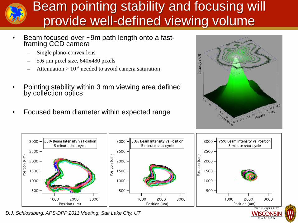
Beam pointing stability and focusing will provide well-defined viewing volume
• Beam focused over ~9m path length onto a fast-framing CCD camera
– Single plano-convex lens – 5.6 µm pixel size, 640x480 pixels – Attenuation > 10-6 needed to avoid camera saturation
• Pointing stability within 3 mm viewing area defined
by collection optics
• Focused beam diameter within expected range
D.J. Schlossberg, APS-DPP 2011 Meeting, Salt Lake City, UT
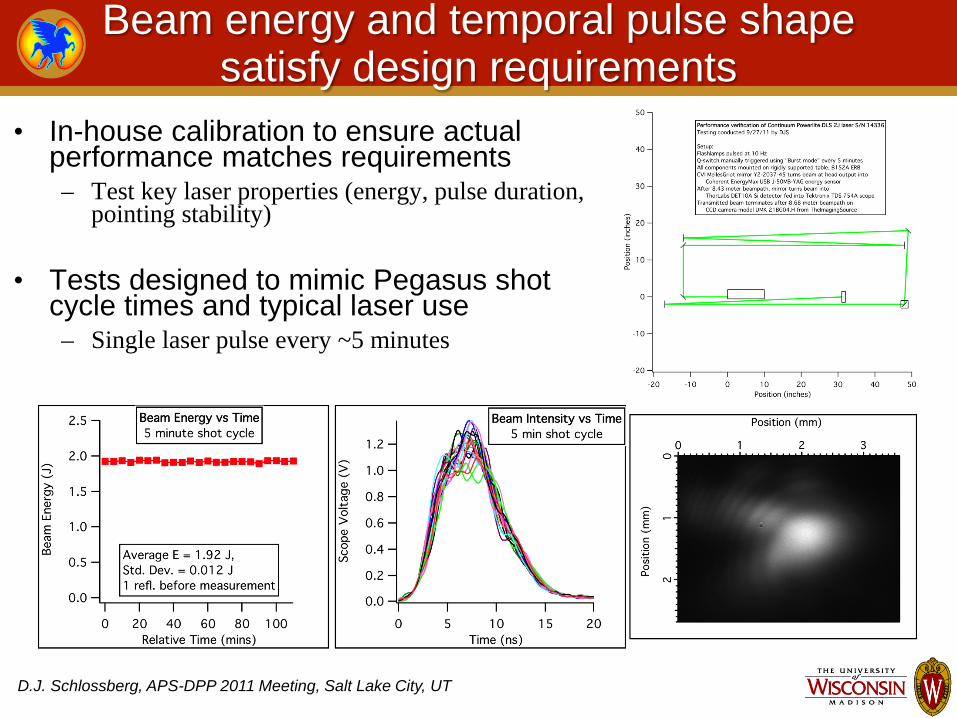
Beam energy and temporal pulse shape satisfy design requirements
• In-house calibration to ensure actual performance matches requirements – Test key laser properties (energy, pulse duration,
pointing stability)
• Tests designed to mimic Pegasus shot cycle times and typical laser use – Single laser pulse every ~5 minutes
D.J. Schlossberg, APS-DPP 2011 Meeting, Salt Lake City, UT

Full-power beam diameter matches design specification
• Burn paper used to measure beam diameter at or near full-power
– As beam is focused, unattenuated energy density becomes too large for burn paper
– Use OD(1) high-power dielectric attenuator to reduce energy
• Unfocused beam diameter ~10 mm • Diameter varies by <25% over expected plasma radius • Long-focal length lens allows convenient fine-tuning on
optical table
D.J. Schlossberg, APS-DPP 2011 Meeting, Salt Lake City, UT

Scattered intensities ~μWatts for typical Pegasus plasmas
D.J. Schlossberg, 19th HTPD Conference, Monterey, CA May 2012
• Preliminary calculations yield scattered intensities of ~4×10⁴ total photons, assuming: – incoherent, non-relativistic
scattering – 2J, 7 ns Nd:YAG laser pulse – solid angle of ~0.01 ster/channel
• Pegasus plasma durations are ~30 ms – Will only be able to measure one
laser pulse per plasma shot
𝐼𝑑𝑒𝑑 =𝐸𝑙𝑙𝑠𝑒𝑙𝐸𝑝𝑝𝑝𝑑𝑝𝑖
𝜎𝑛𝑒𝑙𝜉4𝜋
= 𝐸𝑙𝑙𝑠𝑒𝑙𝜆𝑙𝑙𝑠𝑒𝑙ℎ𝑐 𝜎𝑛𝑒𝑙
𝜉4𝜋
≈ 2.66 × 10¹¹ 𝑠2 𝑘𝑘⁄ 𝐸𝑙𝑙𝑠𝑒𝑙 ⋅ 𝜆𝑙𝑙𝑠𝑒𝑙 ⋅ 𝑛𝑒 ⋅ 𝑙 ⋅ 𝜉
Symbol: Inputs:Elaser Laser output energy (J) 2
λ i Incident laser wavelength, λm (m) 5.32E-07
ne Electron density (m-3) 1.00E+19l Length of beam for one channel (m) 0.014ξ Solid angle subtended by optics (ster) 9.23E-03
Pulse duration (s) 7.00E-09
Output:Ilaser Number of laser photons incident/pulse 5.35E+18
Idet Number of photons scattered/pulse 36582.10Joules incident at primary wavelength 1.37E-14Watts at primary wavelength 1.95E-06

0.00E+00
1.00E+14
2.00E+14
3.00E+14
4.00E+14
5.00E+14
6.00E+14
7.00E+14
8.00E+14
9.00E+14
464 484 504 524 544 564 584
Scat
tere
d Po
wer
(AU
)
Scattered Wavelength (nm)
Theoretical scattered power for 10 eV < Te < 500 eV
Incident Wavelength10 eV50 eV100 eV250 eV500 eVBin size = 60 nm
Spectral range 532 – 592 nm for Pegasus operating scenarios
D.J. Schlossberg, 19th HTPD Conference, Monterey, CA May 2012
• Pegasus plasmas expected to have 10 eV < Te < 500 eV
• Use high dispersion VPH grating for low temperatures:
– 532 nm < λinc < 562 nm
• Use low dispersion VPH grating for high temperatures:
– 532 nm < λinc < 592 nm
• Signal levels will likely dictate ∆λinc ≈ 4 nm and 8 nm in the low and high temperature cases, respectively
• Predictions assume 90° average scattering angle with ~10-2 solid angle – Relativistic effects evident in shift of central wavelength at Te > 500 eV
Based on: J. Sheffield, “The Incoherent Scattering of Radiation from a High Temperature Plasma”, Plasma Phys., 14, 783-791, 1972.

Custom Collection Optics Designed and Fabricated
D.J. Schlossberg, 19th HTPD Conference, Monterey, CA May 2012
• 4 element lens system with 134 mm dia. aperture stop
• 132 cm2 on-axis collection area with object distance ~80 cm
• Collection: ~F/6
• Imaging: ~F/1.75
• Able to view r/Rvessel = 0.16-0.84, collects over 63° < θscattering < 110°
• Mounted on a vibration-isolated stand, free-standing from vacuum vessel
• Fiber optic holders can be placed anywhere along lens’ image plane

Collection Lens System Characterized
D.J. Schlossberg, 19th HTPD Conference, Monterey, CA May 2012
• Laboratory testing shows ~50% contrast for all spatial locations at 2.25 line pairs/mm
– 1951 USAF resolution test chart used – In-vessel imaging area 3 mm x 14 mm
• Lens system is slightly anamorphic
– Horizontal magnification ~0.40 – Vertical magnification ~0.42
Collection Lens Resolution (Modulation Transfer Function)
Collection Lens Magnification • System designed by Wright Scientific, Inc. and modeled in ZEMAX

Initial System Designed for Expandability
D.J. Schlossberg, 19th HTPD Conference, Monterey, CA May 2012
• Inidividual channels correspond to close-packed fiber bundles – 1.5 cm radial resolution
• Initially, 4 data channels and 4
background monitors – Evaluate performance & plasma
conditions and reconfigure as needed
– Upon successful implementation, immediately begin expanding to 16 additional channels
• Scan array radially from shot-to-shot – Initially manual positioning – Expand to automated positioning
across curved collection optics focal plane

Novel spectrometer system employs VPH grating and ICCD camera
• Custom achromat entrance lens
• Custom Volume Phase Holographic (VPH) diffraction gratings
• Image Intensified CCD (ICCD) detector
– High quantum efficiency Gen 3 Intensifier
– Fast gating capability down to 1.2 ns
RCWA Theoretical VPH Grating Efficiency, 2971 l/mm
Diff
ract
ion
Eff
icie
ncy
(%)
0 10 20 30 40 50 60 70 80 90 100
525 530 535 540 545 550 555 560 565 570
Wavelength (nm)
Courtesy of J. Arns, Kaiser Optics Systems, Inc.
D.J. Schlossberg, 19th HTPD Conference, Monterey, CA May 2012

Synthetic data created in IGOR
D.J. Schlossberg, 19th HTPD Conference, Monterey, CA May 2012
• Based on Sheffield’s model/corrections for Thomson scattering: 1. Starts with exact results 2. Duplicates for each row in given channel 3. Adds photon noise from scattering 4. Adds estimated background signal from
plasma 5. Adds detector dark current + dark
current noise 6. Adds camera baseline offset 7. Add readout noise from detector
amplifiers 8. Rescales assuming data is optimized for
detector’s full dynamic range (16-bit)
Spatial Channels
Wavelength
𝑑𝑠𝑖 𝑅, 𝜆𝑠 𝑑𝜆𝑠𝑑Ω =𝑑𝑖𝑟02𝑑Ω𝑛𝑒𝐿𝑐
2𝜋1 2⁄ asin 𝜃 2⁄ 𝜆𝑖⋅ 1 −
72Δ𝜆𝜆𝑖
+𝑐2Δ𝜆3
4𝑎2𝜆𝑖3 sin2 𝜃 2⁄
× exp −𝑐2Δ𝜆2
4𝑎2𝜆𝑖2 sin2(𝜃 2)⁄⋅ 𝑑𝜆𝑠
where the incident power 𝑑𝑖 = 𝑖𝐸𝑖
2
8𝜋𝐴 and 𝑟0 = 𝑒2
𝑚𝑖02= 2.82 × 10⁻¹³𝑐𝑚
See: J. Sheffield, “The Incoherent Scattering of Radiation from a High Temperature Plasma”, Plasma Phys., 14, 783-791, 1972.
Synt
hetic
Imag
e

Initial data analysis routine begun
D.J. Schlossberg, 19th HTPD Conference, Monterey, CA May 2012
• Initial data routine coded to obtain temperatures: 1. Uses 1024x1024 image as input 2. Bins data in “spatial direction” 3. Bins data in “dispersion” direction 4. Applies Gaussian curve to obtain FWHM 5. Converts to temperature using exponential
coefficients from Sheffield

Several calibration methods under consideration
D.J. Schlossberg, 19th HTPD Conference, Monterey, CA May 2012
• Typical calibration methods span orders of magnitude in cross-section: – σRayleigh ≈ 10-28 cm2/sr – σRaman ≈ 10-31 cm2/sr – σThomson ≈ 10-33 cm2/sr
• Alternate methods include: – Comparison with existing Pegasus
diagnostics (ex. µwave interferometer)
– Vacuum-compatible calibrated source, actuated to move along beamline
Typical PEGASUS plasma density
NSTX Raman Calibration From LeBlanc, Rev. Sci. Instr. 79, 10E737 (2008)
Raman spectrum Polychromator spectral bins

Vacuum-compatible insertable calibration assembly designed
D.J. Schlossberg, 19th HTPD Conference, Monterey, CA May 2012
• Single assembly with 2 configurations: – Spatial Calibration: Brewster
angle window, reentrant tube, scatter-plate
– Spectral Calibration: Fiber optic vacuum feed-through, reentrant tube, fiber-coupled integrating sphere
• Could be use in addition to, or instead of, Raman/Rayleigh scattering

Bremsstrahlung emission a tolerable fraction of scattered signal
• Predicted Bremsstrahlung emission shows ~photons/nm collected
– Short collection time (8ns) – Moderate single channel viewing volume
(231 cm3)
• Actual Bremsstrahlung measured
with scanning spectrometer – Small peaks within Thomson collection
spectral range
• Choice of spectral collection region
avoids Dα and N2 lines
D.J. Schlossberg, APS-DPP 2011 Meeting, Salt Lake City, UT
Measured Bremsstrahlung Spectrum
560 580 520 540 Wavelength (nm)
Mea
sure
d In
tens
ity (A
U)
10 8 6 4 2 0
14 12
0
2
4
6
8
10
520 540 560 580
# of
pho
tons
Wavelength (nm)
Predicted Bremsstrahlung Emission* per 8 ns pulse from 231 cm3 scattering volume
*following Karzas and Latter, Astrophys. J. (Supplement) 6 1961, 167

Precision timing provided by tunable delays
D.J. Schlossberg, 19th HTPD Conference, Monterey, CA May 2012
• Sub-nanosecond synchronization necessary between components – User requests laser pulse at given time t0 during shot – Pegasus control code issues Timing Sequence Module (TSM) pulse at (t0 – tflash
lamps – tQ-switch) – Variable Sync Output on laser supply triggers camera acquisition
• Tuned to account for laser propagation time through beamline and electronics calculation time internal to camera
Pegasus Shot Clock
Requested MPTS Time
Start shot End shot TSM pulse
Q-Switch
Variable Sync Laser Output
±150 ns delay
Fast-gated camera shutter Variable camera delay
<8 ns
Flash Lamps (10 Hz)
Single laser pulse initiated by TSM pulse
150 µs
Slow CCD readout
Read out CCD after end of shot

Summary
D.J. Schlossberg, 19th HTPD Conference, Monterey, CA May 2012
• A new Thomson scattering diagnostic has been designed and is being implemented on the Pegasus Toroidal Experiment – 10 eV < Te < 500 eV, 1018 m-3 < ne < ~5×10¹⁹ m-3
• Nd:YAG laser, collection optics, beam dump & beam line have
been characterized and are ready for installation
• Spectrometer testing is nearly complete, and will be ready for implementation in the early summer – Uses Volume Phase Holographic (VPH) diffraction grating, and intensified
CCD (ICCD) camera
• Calibration procedures are under development, and in-situ
methods are being explored