a towing carriage for the university of … tow tank or towing basin is and what makes it better or...
TRANSCRIPT

A TOWING CARRIAGE FOR THE UNIVERSITY OF NEW HAMPSHIRE
TOWING AND WAVE MAKING BASIN
BY
LYNN DARNELL B.S., UNIVERSITY OF NEBRASKA, 1975
THESIS
Submitted to the University of New Hampshire in partial fulfillment of the requirements for the degree of
Master of Science
in
Ocean Engineering
December, 1996

This thesis has been examined and approved.
M. Robinson Swift
Thesis Director
Professor of Mechanical Engineering
Kenneth C. Baldwin
Associate Professor of Mechanical Engineering
~ .. Barbaros Celikkol
Professor of Mechanical Engineering
• Gerald Sedor
Instructor //-2.7-'1t
Date

DEDICATION
To my wife, Donna, for her unlimited
patience and her unwavering support.
•
iii

ACKNOWLEDGMENTS
In the course of this study I was given the opportunity to
visit numerous hydrodynamic test facilities throughout the
country. I wish to thank those people who gave so generously
of their time and knowledge while allowing me such complete
and candid access to their facilities.
I would also like to extend a special thanks to those
individuals who labored with me to make the towing carriage a
reality. Particularly, I would like to thank Paul Lavoie for
his contributions and the time he spent in reviewing and
critiquing virtually every aspect of the design and
construction phases of this study.
Finally, I would like to thank all of the faculty, staff and
students who contributed their time, effort and support
throughout this study.
•
iv

DEDICATION . . .
ACKNOWLEDGMENTS
LIST OF FIGURES
ABSTRACT . . . .
CHAPTER
I. INTRODUCTION
TABLE OF CONTENTS
Historic Perspective
Background Definitions
The UNH Center for Ocean Engr.
Objectives
Approach
II. DESIGN CONSTRAINTS AND SPECIFICATIONS
Anticipated Usage
Detailed Requirements of the
UNH Towing System . . .
v
•
iii
iv
viii
.. x
1
2
8
9
9
11
23

III. REVIEW OF EXISTING DESIGNS
Overview . . . . . . . . . 31
Site Visits to:
Mass. Institute of Tech. 33
Univ. of Rhode Island 40
Woods Hole Oceanographic Inst. 45
U.S. Coast Guard Academy 50
U.S. Naval Academy. . . 57
Naval Surface Warfare Center 62
Naval Undersea Warfare Center 67
Offshore Model Basin . 70
IV. DESIGN ALTERNATIVES FOR THE UNH TANK
Concept Alternatives for the Carriage 74
Concept Selection . . . . 90
Drive System Alternatives 91
Drive System Power Req. & Gear Ratios 97
Motor and Controller Alternatives .. 100
V. CARRIAGE DESIGN AND CONSTRUCTION
System Components .
Cross Tank Carriage Frame
104
104
Primary Rail or Dominant Siderail 110
Secondary or Passive Rail . 114
Dominant Rail Bearing Beam 121
vi

T
Wheels . . . . . . . . . . . . . 126
Cable Attachment and Cable Trough 128
The Cable Path, Including Idle Sheaves
and Tensioning 131
Cable Drive Sheave 131
Motor, Controller and Gearing 135
VI. OPERATIONAL TESTING
Speeds and Acceleration 137
Towing Force Capability 139
Analysis . . . . . . . 142
VI. DISCUSSION
Conclusions . . . . . . . . 146
Comparison to Similar Basins 152
Future Work . . . . . . . . . 156
References 162
Appendix 164
•
vii

LIST OF FIGURES
NUMBER TITLE PAGE
II-1 Force Applied to a Submerged Object in Tow 14
III-1 Side View of the MIT Monorail Carriage 35
III-2 End View of the MIT Monorail Carriage
Showing the Instrument Truck and Outrigger 36
III-3 Surface Object Test Fixture at MIT 38
III-4 Cable Drive Arrangement at USCGA 53
III-5 USCGA Surface Object Test Fixture 56
IV-1 Carriage Velocity vs Propulsion Force 99
V-1 Aluminum, Cross-Tank Carriage Frame 105
V-2 TOp View of the Carriage Frame 107
V-3 Side View of the Carriage Frame 108
V-4 Photo A of Model of Carriage Frame 109
V-5 Photo B of Model of Carriage Frame 109
V-6 Primary Rail Mount Assembly . 113
V-7 Secondary Rail Mount Assembly 118
V-8 Carriage Frame with Bearing Beam 121
V-9 End View of Bearing Beam, Rail & Wheels 123
Top View of Bearing Beam Wheel Assembly 124
• Side View of Bearing Beam Wheel Assembly 124
End View of Bearing Beam with Cable Grab 129
viii
J
V-13 Side View of Cable Grab & Cable . . . 130
V-14 Plot of TT vs a for Various Sheave Conditions . 133 ~
V-15 Required Tension Ratio for a Given Pretensioning 135
VlI-1 Comparison of Tow Tank Lengths 152
VII-2 Comparison of Tow Tank Widths 153
VII-3 Comparison of Tow Tank Depths 153
VII-4 Comparison of Tow Tank Cross Sections 154
VII-5 Comparison of Tow Tank Maximum Speeds 154
VII-6 Comparison of Tow Tank Drive Power 155
A-1 Submerged Object on a Forward Tether 166
A-2 Submerged Object on Stinger Mount . . 168
A-3 Submerged Object on Double Side Struts 171
A-4 Submerged Object at a Steep Angle of Attack 171
A-5 Simulated Bottom Object in Flow, Side View 175
A-6 Simulated Bottom Object in Flow, End View 175
A-7 Surface Tethered Object 177
A-8 Simulated Bottom Tethered Object, Side View 178
A-9 Simulated Bottom Tethered Object, End View 178
•
ix
ABSTRACT
A TOWING CARRIAGE FOR THE UNIVERSITY OF NEW HAMPSHIRE
TOWING AND WAVE MAKING BASIN
BY
LYNN DARNELL University of New Hampshire, December, 1996
This study covers the design, construction and initial testing
of.a towing carriage for a towing basin. The design has been
successfully incorporated into the 36 meter long towing and
wavemaking basin at the University of New Hampshire. A number
of similar, existing towing basins were visited to provide a
basis for the design with the objective of optimizing it. The
study includes a review of those facilities and a comparison
of the various carriage designs. A review of anticipated tow
tank usage is also included. The completed system is a cable
driven, dominant siderail design with a composite main rail
and a light weight, cross-tank carriage. The design and
construction were successfully validated by testing. The
7.5 kW drive system has a tested maximum speed of more than
7.0 mls with a towing force of more than 200~Newtons in its
low speed range.
x
CHAPTER I
INTRODUCTION
Historic Perspective
In 1898, the United states Navy constructed the first
experimental model basin in the United States. The basin was
constructed for testing models of war vessels and was designed
by a young officer who went on to become Admiral David W.
Taylor, world renowned for his achievements in Marine
Engineering. In the original basin that he designed and other
test facilities throughout the country, hydrodynamic testing
has continuously progressed for nearly a century. The field
of hydrodynamics has matured and expanded greatly beyond basic
testing of ship drag and seaworthiness. Studies of modern
control surfaces for submarines, low drag hull designs,
boundary effects on thrusters and even deployment of fishing
nets have been conducted in the laboratory using some form of
testing basin such as a tow tank. This study involves the
evaluation, design, construction and initial testing a towing
apparatus for a hydrodynamic testing basin at the University
of New Hampshire (UNH). •
1

Background and Definitions
A general discussion is appropriate to review the various
forms of hydrodynamic testing apparatus before examining any
specific design. Since some hydrodynamic testing is better
suited for test systems other than a tow tank, such as
cavitation testing of high speed propellers in a pressurized
flow tunnel, review of the special capabilities of other forms
of test apparatus helps to define what the tow tank does not
need for design capability. Readers who already have some
familiarity with hydrodynamic testing and its related
terminology may wish to skip this narrative. Others should
find this background discussion useful in clarifying what a
tow tank or towing basin is and what makes it better or worse
than other forms of test apparatus.
Tow Tank or Towing Basin -- A towing basin is used to measure
hydrodynamic characteristics and performance of objects or
systems moving through a fluid. According to Bishop, et, al.
(1982) the tow tank "is probably the most widely used of all
the test facilities". The basin is normally quite large
relative to the object being tested and long enough to allow
objects to be dragged a worthwhile distance through the water.
Since the objective is to drag, push, or otherwise propel a
unit under test (DDT) through the basin of fluid, towing
basins are invariably equipped with some sort of transport
mechanism specifically designed for towing such test objects.
2

The towing mechanism is referred to as a towing carriage in
this study. In addition to towing capability, many tow tanks
also incorporate wavemaking capability which can be run
separately or concurrently with towing experiments.
Other testing methods exist for making hydrodynamic
measurements to validate hydrodynamic performance. These
methods include water channels, water/wind tunnels, rotating
arm basins and what might be referred to as a vertical basin.
The following brief descriptions are intended to help clarify
the unique characteristics of each.
Water/Wind Channels and Tunnels -- Water channels and water
tunnels, also referred to as flume tanks, are a trough or tube
of continuously flowing water. A water channel is
distinguished from a water tunnel in that a water channel has
a free or open surface for testing, while a water tunnel is a
completely filled tube of water (no free surface). Because of
its confinement, water can be forced through a water tunnel at
higher velocities than a water channel and is more easily
pressurized for special experiments such as cavitation
testing. Testing for cavitation of propellers in pressurized,
high velocity flows is an important type of measurement, and •
systems capable of this type of testing ~re often referred to
as cavitation channels or tunnels. The size of a tow tank is
such that it is all but impossible to pressurize it for
3
'I

cavitation type testing. On the other hand, wavemaking
capability cannot be added to a water tunnel.
Wind tunnels are also used'for fluid dynamic testing.
Actually, the choice of fluid is somewhat arbitrary for many
fluid dynamic tests. Relative drag of automobile shapes can
be compared by testing in water and relative drag of submarine
hulls can be compared in wind tunnels (Hoerner, 1965). The
advantage of wind tunnels over towing basins is primarily that
of lower cost. Rather than circulating large amounts of water
through enormous conduits using large powerful motors, a wind
tunnel merely accelerates ambient air through an open tube,
requiring considerably less power. Cavitation, however,
cannot be measured in a wind tunnel and there is no such thing
as a wind channel.
The water channel most closely approximates the testing
capabilities of a tow tank and is often used as a primary
alternative to a tow tank. Water tunnels/channels have some
advantages because they are physically smaller and usually
cost less. Furthermore, hydrodynamic testing at high flow
rates can continue for an indefinite period of time. By
contrast, the useable test duration, at high transport rates, •
iS,quite brief in even the longest of towing basins.
4

Size is also a disadvantage to water channel/tunnels. Because
they are small, they do not generally accommodate models as
large as those tested in tow tanks. In hydrodynamic tests
which emulate open water conditions, the objects being tested
must be small enough to be placed in the testing cross section
without being in such close proximity to the walls that they
affect the fluid flow around the object. This is true in a
tow tank, but it is even more of a problem in water
channels/tunnels because of their flow profiles. All fluid
channels/tunnels inevitably have flow velocity profiles, which
vary from zero at the tank wall to maximum velocity at or near
the center of the channel/tunnel. This type of velocity
profile results in shear forces and potential vortices which
may not exist for the same test in a tpw tank or a large open
body of water. Such a problem was noted in the oil spill
containment barrier studies by Coyne (1995). Since the water
in a tow tank is generally not moving, an object moving
through the tow tank emulates a fixed object in a current with
all water particles moving at the same velocity. Towing
basins still have wall effects, but they are primarily
pressure deviations due to volume displacement by the object
under test and not shear effects due to a flow profile .
• Rotating Arm Basin -- A rotating arm basin performs tests
Similar to that of a tow tank, but instead of the object being
~oved linearly through a long straight tank, it is rotated
5

around a central point in a large and/or circular tank. Its
specialty is testing surface vehicle models in turning
maneuvers.
vertical Basin -- A key disadvantage of all of the previously
mentioned types of hydrodynamic testing is that the object
under test must somehow be propelled through the working
fluid, or attached to something that either holds it in the
flow or pushes it through the fluid, all of which disturbs the
flow. If the object is either weighted or buoyed and released
in a long vertical column of fluid,_the free motions of the
object and hull acoustics can be measured without the
interference of thrusters or support attachments.
Disadvantages of this method are cost, versatility, lack of
test unit accessibility during testing and dramatic ambient
pressure changes as the test unit progresses. Also, this
method is useable only on fully submerged objects.
Wave Making Basin -- Testing in a wave environment is a
different type of hydrodynamic testing than those previously
mentioned. A towing apparatus cannot emulate wave testing and
a wavemaker cannot test an object moving through water.
However, both types of testing may be run simultaneously, such •
as testing a model of a ship in forward motion as it travels
into waves. For this and other reasons, towing basins usually
have some form of wavemaking capability. Basins referred to
6

as wavemaking basins usually do not have towing capability,
however. Wavemaking basins vary widely in size shape and
configuration. They may be deep, shallow, or sloped like a
beach. Their wavemakers may create deep water waves, shallow
water waves, oblique waves, etc. A more detailed review of
waves and wave generators may be found in the study by
Washburn (1995). Wave basins are used to test the effects of
waves on ships, manmade structures, beach erosion, pollutant
dispersion etc.
•
7

The University of New Hampshire, center for Ocean Engineering
In November of 1994, the Center for Ocean Engineering at the
University of New Hampshire (UNH) opened the doors of a new
building with facilities dedicated to study and research in
the ocean engineering fields. The building's hydrodynamic
test facilities include a water channel and two large fresh
water basins. The water channel is 1.2 meters wide by
0.9 meters deep with a useable test section about 7.0 meters
long. For more information on the water channel refer to Doan
(1994) and Coyne (1995).
Of the two large fresh water basins, the larger is designed as
a general use deep water tank. The length, width and depth
are 18.3 x 12.2 x 6.1 meters (60 x 40 x 20 ft) respectively.
The second, longer basin is intended for use as a towing and
wave generation tank. Its respective dimensions are 36.6 x
3.7 x 3 meters (120 x 12 x 10 ft). This study focuses on the
investigation, design, construction and testing of the towing
system or carriage for the longer basin.
The tow tank, or towing basin, is supported by a water
distribution and filtration system which is separate from the
• larger basin. The tow tank has a wavemaker (water backed,
bottom hinged, hydraulically driven, flapper type) occupying
3.5 meters at~one end of the basin and a wave absorber
8
occupying 3.7 meters at the other end. Both the wavemaker and
wave absorber are described in detail in the study by Washburn
(1995). Prior to this study, no towing or propulsion system
was in place or designed for the tow tank.
Objectives
The objective of this study is to evaluate, design, implement
and test a towing mechanism or carriage for the towing basin.
The towing carriage is the mechanism or method by which
various objects under test are to be pushed, pulled or
otherwise thrust through the water in the basin.
Approach
Prior to pursuing the actual design, the expected usage of the
towing system was investigated, including what types of
testing might be expected, as well as how those tests may be
implemented. As part of this study, similar facilities within
~ the geographic region were visited and evaluated with respect
to each other, and with respect to the UNH facilities.
Infor~ation was gathered to define general design parameters,
such as maximum carriage velocity, maximum load and structural •
arrangement, in order to maximize the system's versatility.
From this information fundamental design specifications were
generated to provide a basis for evaluating a carriage design.
9

Basic carriage designs were postulated and reviewed, along
with various drive systems appropriate for the selected
carriage arrangement. Parameters taken into account in
selecting a basic carriage and drive system included cost,
safety and maintenance in the university environment,
modularity of subsystems, smoothness of operation, carriage
rigidity and strength, versatility, and design simplicity.
Having selected a basic carriage design, a detailed design was
developed and constructed. The detailed design and
construction proceeded concurrently. The subsystems were
designed and constructed as modular components. These modules
were then integrated. After completion of the design and
construction phase, the carriage and drive systems were tested
and re-evaluated to establish the actual system
specifications. A detailed description of the design and
construction follows.
•
10

I,
CHAPTER II
DESIGN CONSTRAINTS AND SPECIFICATIONS
Anticipated Usage
The most common types of tests in a tow tank would probably be
modeling and testing of the forward drag and stability
characteristics of a scale model of a surface vehicle or
submerged object. The UNH tow tank will be expected to handle
either of these tests as well as a variety of less foreseeable
types of tests. This section attempts to predict, categorize
and evaluate the types of tests which could be conducted using
the tow tank, and to assess their relative impact on the
carriage design.
Throughout the study the need arises to refer to positive
directions of axes, moments, forces and angles. For clarity
of discussion, the X-Y plane shall be parallel to the tank's
water surface with the positive direction of the X-axis
pointing towards the wavemaker and parallel to the tank's
length. The Y-axis shall be defined as horizontal and
transverse to the direction of carriage travel. The positive •
Z-axis shall be defined as perpendicular to the water surface
and pointing downward. A more thorough description and
definition of the positive directions of axes, moments,
11

forces, etc. may be found in Abkowitz (1969) and/or Humphreys
(1976) .
Examination of how the various experiments are fixtured during
testing helps to illuminate the various forces and motions
encountered by both the object under test and the carriage.
Exploration of these forces and motions helps to define how
the carriage must be designed to accommodate those tests. To
this end, fixturing requirements for the different types of
tests were explored and are summarized in the appendix. While
the general test categories explored and summarized could also
include some form of simultaneous wave testing, the scope of
this evaluation is limited to tow testing. System tolerance
to and measurement of wave effects is expected, but no effort
has been expended towards the investigation of wave generation
or its measurement. For assessment of impact on carriage
design, testing was broken into categories of submerged
objects (untethered), surface objects, bottom mounted objects
in a flow and various tethered objects. These testing
categories are analyzed in the following paragraphs.
Submerged Object Testing -- For purposes of this discussion, a
submerged object shall be defined as an object or vehicle •
'whose motions, and the forces applied to it, are independent
any reference to solid surroundings, including those forces
t might be applied through a tether. Examples of such
12

objects include submarines, fish, autonomous underwater
vehicles, etc. By so defining it, all submerged objects have
freedom of movement in all six degrees of freedom. Motions of
a submerged object are governed by hydrodynamic forces,
acceleration of inertia and gravitational forces. The
equations of motion for submerged objects are defined in
Abkowitz (1972) or Humphreys (1976). In the absence of
boundaries, equilibrium solutions to these equations of motion
do not generally determine absolute X, Y and yaw positions.
steady state solutions for pitch and roll position may exist
as a result of righting moment, and a Z-axis equilibrium
condition may exist in a fluid with a vertical density
gradient. All other test types are restrained to the surface
or other boundary or to a tether, and include these
restraining boundaries as part of their equilibrium forces.
studies of submerged objects tend to focus on measurement of
drag and lift forces, or hydrodynamic flow around that object
and its appendages or control surfaces. Actual free body
motions of a submerged object are of interest, but are not
generally tested directly in a tow tank. They are, instead,
predicted and modeled from measurements of the forces and
flows. To measure forces other than steady forward drag, the
• object or unit under test (UUT) is held fixed in all axes and
except the X-axis. Force measurement devices (e.g.,
blocks) are then used to observe the magnitude and
13

direction of the resulting forces. The appendix depicts
several methods by which this is accomplished. To observe
surrounding flow patterns, the object is similarly held while
injected dye, hydrogen bubbles, small neutrally buoyant
particles, strings protruding from its hull, or other
indicator allows the flow to be observed.
The UUT is normally held in a fixed position as far from any
tank boundary as possible. The object is therefore placed
close to the centerline of the tank during testing.
Positioning an object in the hydrodynamic center of the water
column in the 3.0 meter deep tank places it at least
1.5 meters from the carriage which rolls along the top of the
tank. As shown in Figure II-1 the major force acting on
1 COUNTERING FORCE ON CARRIAGE
CARRIAGE
RESULTING T COUNTERING FORCE ON C RI GE
1.5 IIIETERS SUPPORT STRUT --------..1 : '.
Figure II-1
UUT
DRAG 1 FORCE .... -----'---
FORWARD VEtOCllY
• Force Applied to a Submerged Object in Tow
14

r
the submerged object, the forward drag, is parallel to the
motion of the carriage at a distance of at least 1.5 meters.
The result is a large moment about the Y-axis or pitch torque.
Because of its depth, the pitch torque forces, from submerged
object testing in the UNH tank, are expected to be quite large
and will affect the carriage design. This pitch torque is
opposed by Z-axis forces over the length of the carriage. The
opposing Z-axis forces invariably come from the wheels or
bearings of the carriage rolling along the top of its rails.
The necessary downward forces may come from wheels/bearings
under its rails, or from the carriage's own weight. To
maximize the usable length of the basin, carriages are often
kept short along the X-axis. If the carriage is not long, the
distance between wheels/bearings is short, and the Z-axis
forces necessary to overcome the pitch torque become large.
If the downward forces are generated by the carriage's own
weight, the carriage mass must be sufficiently large to keep
it from tipping. However, a large carriage mass tends to
result in poor acceleration, thus shortening the useable test
zone and compromising the overall performance of the tank.
Modeling of submerged objects, which is usually necessary to
meet boundary constraints of a tank, requires increased speed.
A submerged object, which is subject only to frictional drag,
is modeled by keeping its Reynolds number (Re) constant
15
, !
, I I
, , , '
! I
,I

(Hoerner, 1965). Reynolds number is defined by the following
relationship:
Re = V ./. p = (2· V)(1I2)p
J.l J.l
(1 )
Where V is the forward velocity, / is the geometric length,
p and J.l are the density and viscosity of the working fluid,
respectively. Therefore, testing of a model half the length
(/12)of the original object requires that the model travel at
twice the speed (2·V) of the original to emulate its
performance.
other forces asserted on the carriage, as a result of forces
on the submerged object, will have less impact on the carriage
design. Lift (Z-axis) forces on the object are countered by
either wheel/bearings pushing against the rails, or by the
weight of the carriage. Large lift forces, such as those on
wings or control surfaces, can usually be directed arbitrarily
upwards or downwards as a result of the orientation of the
UUT, allowing the test set up to be optimized to the carriage.
Normally, submerged objects in a flow are inherently left
symmetrical, or close to it (fish, torpedoes,
~uu1l'larines). Any asymmetric forces on the object would make • ahead free body movement difficult. As a result, yaw
~orces from a submerged object are expected to be
gible with respect to the carriage design. X-axis
16
i:
i'
I

r I i
forces, as a result of forward drag, may be large as a result
of forward speeds, but other types of testing may produce
larger X-axis forces.
Surface Object Testing -- For purposes of this discussion,
surface objects shall be defined as free floating,
unrestrained, objects on the surface of water (e.g., boats and
barges, not tightly moored floats or large booms). Although
forces such as drag and lift can be measured on a surface
object, the parameters of interest are usually the movements
of the UUT as opposed to the forces on it. Such would be the
case for most seakeeping measurements. Instead of rigidly
holding the object and measuring the forces, the object is
allowed as much freedom of movement, in as many axes as is
possible or desired, and its movements are measured. Because
the~ are deliberately unrestrained, testing of surface obj~cts
(as described in the appendix) will generally apply to the
carriage only X-axis forces caused by drag of the object.
These forces may be large, but no larger than for other forms
of testing. The only forces applied to a surface object which
might affect the carriage design are cyclic forces caused by
testing during wavemaking. Although these forces may be
L ~ , !
• small, their effects could be significant if the cyclic forces I Occur at or near a resonant frequency inherent in the carriage
and drive system.
17

r ,
In those instances where a force is being measured on a
surface object, the drag force acting in a direction opposite
to the motion is usually the measurement being sought. Model
testing to determine this drag force is more complicated than
that of a submerged object. Viscous drag measurements are
handled in a manner similar to submerged model tests, but
surface objects are also subject to wavemaking effects. To
model wavemaking effects, the Froude number (Fn) is held
constant. Fn is defined as follows (Hoerner 1965):
V(l F =~= V2
n fi:t ~g.f (2 )
Gravity (g) being constant, if a model with half the original
geometric length I
(-) 2
is used, its velocity (V) must be
decreased by the square root of the decrease in length
(VH). From a testing standpoint this presents a challenge,
because the half size model must simultaneously go twice as
fast to model frictional flow effects and .707 times its
original speed to model wavemaking effects. This classic
• modeling problem is discussed in Principles of Naval
Architecture (1967). From the standpoint of carriage design,
18

however, the speed requirements are no more demanding than
those of submerged model testing.
Testing of Stationary Bottom Objects in a Flow -- The Center
for Ocean Engineering at UNH has been and will continue to be
involved in research which explores the forces and effects of
tidal flows in rivers and estuaries and on objects placed in
those flows. It is expected that the tow tank will be called
upon to examine the effects on some bottom mounted object in
that flow. An example of such a need can be found ,in a recent
publication by Bilgili (1993). In his study he used a
weighted tripod mount to attach a current meter to the bottom
of the Piscataqua River, so that current velocities could be
monitored throughout a tidal cycle. The obvious question is:
Did the stationary tripod affect the flow past the current
meter? The assessment was that the tripod mount did not
induce a significant error in tidal current measurement. That
accuracy might have been confirmed in a properly equipped and
instrumented tow tank.
Of importance to the carriage design, is that potentially
large pitch forces are generated in testing a bottom object in •
a flow, especially if fixtured as described in the appendix.
These large forces are the result of the UUT's drag force and
the distance between carriage and UUT, which may be more than
19

3.0 meters. Because UUTs may be emulating obstructions in a
flow (e.g., a structure on the bottom of a river) the objects
may have large drag coefficients. In addition, for the
platform to which the UUT is attached to effectively emulate a
bottom, stationary with respect to the object, the platform
must be large thereby creating an even larger combined drag.
Tethered Object Testing -- Tethered objects include objects
towed behind a boat on a cable (side scan sonar), bottom
anchored floats in a flow (marker buoys or more complicated
mooring systems), and arrays requiring two or more points of
attachments (fishing nets and oil containment barriers). In
all of these cases the only connection between the carriage
and the UUT is a tether. The fact that the carriage and UUT
are not rigidly coupled restricts most testing of tethered i
objects to tests which observe the motions of the object and
its tether. The only force which can be easily investigated
is tether tension, which is a composite of the forces due to
buoyancy, drag and lift.
From the standpoint of carriage design, testing of tethered ,: . ,
objects is the least demanding in terms of requirements for
smooth carriage motion and rigidity of the carriage against •
forces applied to it. Because of the size and large drag
coefficients of towed arrays (such as fishing nets and oil
containment barriers), this category of testing did produce
20
the highest predicted towing forces. In developing the design
requirements for the towing system, a towed oil containment
barrier dictated the maximum towing force requirement (as
discussed in Detailed Requirements) .
Calibration of Current meters -- Tow tanks are ideal
facilities for calibrating most current meters, and future
uses of the UNH facility are expected to include such
operations. Current meters are generally small enough that
hydrodynamic wall effects are not a problem in a tank as large
as the UNH tank. Also, they place no rigorous strength and
rigidity demands on the carriage as compared to other
categories of testing. This category does have a couple of
unique requirements which ultimately impact the carriage
design, however. Current meter calibration requires accurate
determination of forward carriage speed and a low
electromagnetic noise environment. Solid state (with no
impeller or moving parts) current meters, such as the S-4
current meters made by InterOcean Systems (1994), are
sensitive to electromagnetic noise. The S-4 meters measure
current by generating a magnetic field around the sensors and
detecting hydrodynamic flow by measuring the voltages
generated by the water borne ions passing through the field . •
These instruments are intended to be placed in open water,
where they would not normally be subject to stray
electromagnetic fields and currents. The impact of this
21
I; . ,Ii
I
il • Ii
! II ,
I
. . i

r application on the design of the carriage and drive system is
to require a minimum of such external noise. Magnetic ! fluctuations due to reinforcement steel in the tank wall
cannot be avoided, but dissimilar metals and poorly shielded •. !: I "
electronics or wiring can be avoided in the design. The need
for accurate forward carriage velocity can be met with proper
carriage instrumentation.
I ,1 I
, i
i!
•
22

Detailed Requirements of the UNH Towing System
The tow tank carriage, as stated earlier, will be called upon
to push, pull or otherwise move miscellaneous objects or
systems through the water while allowing for various
observations to be made or measurements to be taken. It may
also be called upon to hold such items stationary while waves
or other forces act upon the UUT. This section attempts to
itemize and, where possible, quantify the towing system's
requirements.
Carriage Propulsion Power -- The drive system shall be capable
of propelling the carriage, with a load, over a wide range of
forces and speeds. Of the known future tests to be run in the
tow tank, large oil barrier systems, as investigated by Coyne
(1995) and Swift et al. (1995,1996), produced the highest
anticipated drag force of 3100 Newtons (700 lbf). This
maximum estimated force was calculated at a speed of 1.3 mls
(2.5 knots). Excluding losses, drag force multiplied by
velocity is about 4.0 kilowatts (5.4 hp). The estimates of
speed and towing force were received directly from Professor
Swift in anticipation of further testing of the system .
• Another arbitrary load was approximated to be that of a
1.0 meter submerged sphere moved through the water at a
23

forward velocity (V) of 2.6 mls (5.0 knots). Powering
requirements are
P=O.5.p·CD ·A.V' (3)
Using a fresh water density (p) of 1.0 kg/m3 , a drag
coefficient (CD) of 0.47 (Hoerner, 1965), and a frontal area
(A) of.0.785 m2 , the resulting power requirement is 3.24 kW
(4.35 hp). Other speculative loads could also have been
calculated, but the two loads identified already dictated an
effective power delivered to the load of more than 4.0 kW
(5.4 hp). Most other considerations, including smaller
objects at faster speeds, did not indicate greater power
requirements. Hence, the design specification for the system
was established as a minimum of 4.0 kW.
Maximum No-Load Speed -- One of the most readily available
statistics on all of the tow tanks investigated was the
maximum speed. The effective length of the basin is reduced
by the length of a wavemaker at one end of the tank and .a wave
absorber at the other end. At high carriage velocities, these
factors, together with the need for acceleration and • deceleration zones, result in a significant reduction in its
useable length. To fulfill reasonable testing expectations
and to achieve capabilities at least comparable to other tow
24

tanks in the region, the maximum forward design speed was
established as a minimum of 2.6 mls (5.0 knots) and preferably
exceeding 5.2 mls (10 knots).
Bi-directional Towing Capability -- The towinglwave basin has
a wavemaker at one end and a wave absorber at the other.
Although wavemaking capability is not a direct part of this
study, consideration of such wavemaking during tow testing is
pertinent to the carriage design. An important consideration
is that of the towing carriage's ability to tow objects
towards or away from propagating waves. Towed objects,
especially towed surface objects, may exhibit significantly
different performance when towed into the waves, as opposed to
away from the waves. Because of this, the carriage and drive
system shall be capable of towing in either direction.
Maximum Towing Force The maximum towing force requirement
was clearly dictated by the oil barrier systems referenced in
the previous paragraph on power requirements. The design
maximum towing force was established as 3100 Newtons (700 lbf)
at speeds below 1.3 mls (2.5 knots).
• Maximum Pitch Torque -- The maximum Pitch torque requirement
results from either a submerged or a bottom mounted load, as
described in the appendix. A bottom mounted load is farthest
25

from the carriage, thus has the longest moment arm, but
submerged loads will probably be tested at significantly
higher velocities. To establish a realistic maximum pitch
torque, the one meter diameter submerged sphere used to
establish carriage drive power requirements was examined with
respect to applied pitch torque. Using the same 2.6 mls test
velocity (V) and other parameters used in calculating the
power requirements of the sphere, the drag (FD ) was found to
be
FD =0.5p·CD ,A.V2 =1,250 Newtons (280 lbf) (4 )
The basin of the tow tank is 3.0 meters deep, but is normally
filled to only 2.5 meters. The center of a sphere placed in
the 2.5 meter water column would be at a distance (d) of
1.8 meters from the top of the basin walls. The resulting
torque (T) applied to a carriage at that distance from the
test sphere is 2,250 Newton-meters (1660 ft-lbf). From this
the maximum pitch torque was established to be 2700 Newton
meters. The carriage shall withstand such forces without
damage or derailment.
Safety -- Of paramount importance to the overall design of the
towing carriage system is safety, both in constEuction and
operation of the system. The nature of the towing system of a
tow tank as large as the UNH tank is that it employs power and
26

moves masses of such magnitude as to be extremely dangerous if
not utilized with appropriate care. Injuries could result
from accidental entanglement, inadvertent leaning on rails
with the system active, electrical shock, snapping drive
cables or even drowning.
The building and the facilities within are under supervision,
but both are accessible at times when they are not supervised.
Also, because it is a university environment, regular
maintenance and inspections prior to each use cannot be
guaranteed. To insure that, in spite of the potential for
negligence and lack of maintenance, risk of serious injury is
kept to a minimum, all reasonable safety considerations should
be adopted throughout the design. For example, items such as
ground fault interruption (GFI) of electrical power, enclosed
drive cables, and minimally accessible rails shall be strongly
considered.
Versatility __ Because of the broad range of tests which can
be run in the tow tank and the inability to predict exactly
what tests will be run in the tank, versatility of the
carriage system must be maximized. All of the tests described
previously should be allowed for in the design of the towing
system, as well as allowing for easy modificati~n for tests
not predicted.
27

Ease of Use -- The system shall be user friendly. The towing
system and controls are not expected to have a dedicated
technician and will see intermittent levels of use over its
years of operational life. Much, if not most of its operation
will be conducted by first time users. As such, its overall
usefulness as a tow tank is dependent upon the ease with which
a first time user can set up, run a test and record accurate,
repeatable, verifiable, data synchronized with time, position,
or both as the resulting data requires. Although this
requirement is heavily dependent upon the instrumentation and
controls which are not addressed in this study, items such as
test unit attachment and maintenance shall be considered.
Minimal Maintenance -- The system shall not require rigorous
detailed maintenance or inspection on a weekly or even monthly
basis for safe reliable operation. Use of corrosion
resistant materials shall be maximized. Inspection and
maintenance shall be minimized and incorporated on a prior to
use checklist as opposed to a periodic schedule.
cost -- Cost shall be minimized wherever possible without
unduly compromising safety, performance and usability. Long •
term costs, such as maintenance, as well as short term costs
shall be considered when evaluating various design tradeoffs.
28

Instrumentation -~Although this study does not address the
actual implementation of the instrumentation or controls of
the carriage, the following capabilities are anticipated. At
a minimum, the carriage shall have time and distance
synchronous logging of the following:
Time continuously logged to the nearest 0.10 sec
position ~5.0 cm along the travel axis
Velocity ~0.05 mls updated every 0.10 meters
Water Height -- ~1.0 cm relative (for wave meas.)
Logging of these parameters shall be implemented in such a way
as to be synchronized with data from force blocks, pressure
transducers, angle potentiometers and other pertinent sensors
which might be utilized in hydrodynamic testing. If possible,
synchronous collection of at least one channel of video should
also be considered.
On Carriage Electrical Power -- For support of various
instrumentation, the carriage shall, at a minimum, have on
board electrical power in the form "of, 120, VAC at 60 Hz. This
electrical power is expected to be from onboard batteries
through a DC to ACconverter, so that the carriage has no
electrical umbilicals while in motion. Actual implementation
of an onboard power system is not addressed in this study .
•
Data Communication Link -- The carriage system shall have some
form of data communications link such that permanent, as well
29
" ,Ii
I
!

as add on, instrumentation can be actively linked to an off
carriage computer. The data link or links shall be
sufficiently broad band to handle all of the previously
mentioned data to be logged, as well as at least one channel
of simultaneous real time video. This communications link is
expected to be wireless, but its actual implementation is not
addressed in this study.
•
30

CHAPTER III
REVIEW OF EXISTING DESIGNS
Overview
To evaluate potential problem areas, critical areas of design
and alternative methods of tow tank implementation, several
similarly sized basins were visited and evaluated. The
facilities visited were:
MIT, Massachusetts Institute of Technology, in Mass.
URI, University of Rhode Island
WHO I , Woods Hole Oceanographic Institute in Mass.
USCGA, United states Coast Guard Academy in Conn.
USNA, The United states Naval Academy in Maryland
NSWC, Naval Surface Warfare Center, Carderock Div.
in Maryland
NUWC, Naval Undersea Warfare Center in Rhode Island
OMS, Offshore Model Basin in California
The basic specifications of each of the tanks, along with as
much objective and subjective information as possible, is
compiled in the ensuing report. All of the loc~tions visited
were openly supportive of my efforts to review their
respective facilities. In the spirit of that openness, the
31

information incorporated into the description of each is as
open and accurate as possible. Any opinions or editorial
comments comparing facilities and systems are included solely
for the purpose of identifying some of the thinking which led
to design criteria and decisions on the final layout of the
propulsion system for the UNH tank. Any statement which
overrates or demeans one of the facilities, in any way, is
strictly unintentional.
•
32
. J , . I , j
: j! , , ~
i I

Massachusetts Institute of Technology
Location: Cambridge, Massachusetts I , '
I
I, contact Person: Dave Barrot, Graduate Student
Phone: 617-253-4348
Basin size: Length: 33 meters (108 feet)
Width: 2.6 meters 8.5 feet)
Depth: 1.5 meters 5.0 feet)
Primary Function: Extensive research in hydrodynamics
and ~n educational lab for classes
such as naval architecture.
Maximum Tow Speed: 4.0 m/s (13 ft/s, 7.7 knots)
Wavemaker: Water backed, computer controlleq,
hydraulically driven, bottom hinged,
flapper type.
other Facilities:
Wave Basin 11 x 17 x 0.6 meters
• Cavitation Tunnel 0.5 m sq. x 1.2 m long
Water Channel 0.6 m square x 25 m long
Water Channel 0.38 x 0.5 m x 20 m long
33

The tow tank at the Massachusetts Institute of Technology
(MIT) is supervised by a faculty member, but operated and
maintained by the students. The tank is used extensively for
research of various types and also supports classroom studies
in naval architecture, etc. The tank is located in a basement
and is bordered on one side and one end by the building's
outside concrete walls. The other side is openly accessible
and a windowed wall is constructed on the remaining end. This
end wall separates the tow tank from a small room which houses
most of the extensive computer equipment and drive control
system for the carriage. Presumably, the wall is intended to
minimize humidity and chlorine contamination of the computer
room. The floor is slightly elevated in areas around the tank
allowing for easy access over the side wall. The top of the
accessible side wall is 1.2 meters above the raised floor.
The ceiling height presents some inconvenience because it is
low. Although a person can stand on the staging area on the
top of the tank, around the carriage, and over the wavemaker,
a tall individual cannot stand upright. The 1.5 meter depth
and 2.6 meter width of the tank dictates the use of relatively
small test models, thus access to the tank and overhead
clearance does not seem to be a serious problem. The 33 meter •
length of the tank was evidently dictated by choice rather
than limitations in the architecture of the building. Loss of
34

length to the wavemaker and wave absorber reduces useable
length to about 30 meters.
The most impressive and unique feature of the MIT tow tank is
the overhead monorail type towing carriage. The monorail
consists of a single 7.6 cm dia x 0.32 cm thick (3.0 in dia x
0.125 in) stainless steel pipe accurately suspended from a
heavy overhead beam running the length of the tank. The
carriage itself travels along the rail suspended on multiple
hard rubber roller skate wheels. The carriage is propelled by
a single, thin, high tensile strength steel strap from a
1.5kW (2 hpj servo motor at the computer room end of the
tank. Wheels located above and below the rail, as shown in
Figure 111-1, restrain the 1.8 meter long carriage in all but
the roll and travel (X) axes.
OVERHEAD I BEAM
3" STAINLESS STEEL PIPE RAIL
CARRIAGE
BOLTS HOLDING RAI,",
Figure III-l Side View of the MIT Monora·il Carriage
35

Z-axis movement and pitch movement are restricted by the
combined upper and lower wheels on the monorail. For most
double siderail systems, this is usually accomplished by the
weight of the carriage on the rails. since weight of the
carriage is not a necessity for restraining the unit under
test (UUT), the mass of the carriage is greatly reduced,
allowing for rapid acceleration of the UUT to a maximum
velocity of about 4.0 m/s with relatively small servomotor.
Roll movement is eliminated by an outrigger arm which rolls
along a second pipe or rail bolted to the side of the tank, as
shown in Figure 111-2.
Figure III-2
~ OVERHEAD
I BEAIIA TOW
"'l:::::J:" ...,..,. STRAP
INSTRUMENT TRUCK ON
CONCRETE SIDE WALL
\
WH ELS
OUTRIGGER ARM TO n THE SIDE RAIL I ~
IDLE WHEEL j SIDE RAIL
End View of the MIT Monorail Carriage
Showing the Instrument Truck and outrigger
• The overwhelming benefit of the overhead monorail design is
that it leaves the open side of the tank completely
36
• I

accessible, clear to lay equipment or paperwork on, and is
safe to lean on (or even lean over) during operation of the
tank. Observation capability on the accessible side of the
tank is further enhanced by an 8.5 meter long subsurface
viewing window. The viewing window was described by the users
as indispensable and has experienced no problems with regard
to leaks or maintenance.
Another benefit of the overhead monorail design is that it
permits the carriage to be propelled by a single steel strap
instead of two matched cables as in other designs. The use of
high tensile strength steel instead of normal cable steel
reduces the stretching, and therefore the springiness, of the
cable drive. The use of a thin steel strap instead of a cable
enables the very brittle steel to bend around the necessary
drive and idle pulleys at either end of the tank. The
overhead carriage also makes possible the ability to counter
the potentially large pitch torque applied to the carriage
without adding a large mass to the carriage. The ability to
counter such large pitch torques is increasingly important in
deeper tow tanks, such as the three meter deep UNH tank.
Standard fix turing for classroom testing of models of surface •
vehicles was observed. The observed fixturing permits freedom
of movement along the vertical axis and pitch angle, but
restricts all other degrees of freedom with respect to the
37

carriage, including roll. Freedom of vertical movement of the
UUT is accomplished by mounting the test object on a long
structural arm parallel to the X-axis (see Figure III-3), with
a bearing on the Y-axis where the fixture attaches to the
carriage. Another bearing is placed at the metacenter of the
UUT, which decouples the structural arm and allows freedom of
pitch movement in the UUT .
.... ________ ARM LENGTH L
CLBEARING
ON Y AXIS
CARRIAGE
STRUCTURAL --~ ARM
BEARING AT LONGITUDINAL METACENTER OF UUT
Figure 111-3 Surface Object Test Fixture at MIT
The advantage of this type of fixture (as opposed to that of
the linear bearing type fixture used at the USCGA) is the low
friction of vertical movement. The disadvantage is that any
movement in the vertical direction is coupled directly into
the X-axis in accordance with the following relationship:
M"'.1Z, (cosO-I) sinO
38
•
(5 )
Where AZis the vertical heave motion, 0 is the angle between
the structural arm and the X-axis and AX is the resulting
forward surge.
Maintenance of the tank is minimal. The rails are corrosion
free stainless steel pipe. The drive strap is semi-enclosed
for safety and no known maintenance has been required since
its installation about 15 years earlier. Good water clarity
is effectively maintained by a swimming pool type of
filtration system and good circulation of the filtered water.
Florescent lights are normally left on 24 hours a day with no
observable algae growth.
•
39

The University of Rhode Island
Location: Kingston, Rhode Island
contact Person: Larry Simoneau, Technician
Phone: 401-874-6242
Basin size: Length: 30.5 meters (100 feet)
(12 feet)
(6.0 feet)
Width: 3.7 meters
Depth: 1.8 meters
Primary Function: Undergraduate classroom instruction
and demonstration. Has been used
extensively in studies of fishing
net deployment.
Maximum Tow Speed: 1.5 mls (5.0 ft/s, 3.0 knots)
Wavemaker: Water backed, hydraulically driven,
bottom hinged, flapper type.
other Facilities:
Acoustic Basin: 3.7 x 7.3 x 3.7 meters •
40

The tow tank at the University of Rhode Island (URI) is housed
in a large room with a high ceiling, and is freely accessible
from all sides. The tank bottom extends below floor level so
that the top of the tank wall is about a meter above the
floor. The open water surface is easily accessible over the
siderails, and could be viewed from either side. Subsurface
viewing windows on one side of the tank allow a limited
underwater view at the halfway point along the tank. '
Consideration was given to the need for these windows to be
flush such that they did not disturb wavemaking. water
leakage around the windows necessitates some maintenance and
interferes somewhat with their usefulness. An elevated
platform over the tank allows additional viewing from above.
The towing carriage is a dual siderail design with an onboard
motor. Four, weight bearing, rubber drive wheels roll along
the top of the rails and four smaller wheels restrain the
carriage in the Y and Yaw axes by rolling along both inside
walls of the tank. The siderails are essentially an aluminum
U channel or C beam, 25 cm wide and 15 cm deep, placed upside
down atop the concrete walls. The standoff distance between
the top surface of the concrete wall and the rail is adjusted
using bolts which are periodically threaded through the beam •
on both sides of the rail. This provides an inexpensive but
effective method of leveling the top of the rail in both the "
'pitch and roll axes. As mentioned above, wheels which ,
I
41 i ~ I'
restrain the carriage in the Y-axis roll along the inside
surface of the rails, but no similar adjustability of the
inside rail face was observed.
3.8 cm solid steel axles, on both the front and rear pairs of
drive wheels, help to constrain the carriage motion parallel
to the tank rails by insuring that wheels on both sides of the
tank are turning at the same rate. Four wheel friction drive
is accomplished using a connecting drive belt between the two
axles. The four wheel drive system helps to reduce wheel
slippage during acceleration of the carriage. The carriage
deceleration capability is augmented with electric brakes.
These brakes provide an excellent method of stopping the
carriage in the event of motor failure. At tank maximum
forward velocity, the brakes might even extend the useable
tank length by shortening the required stop distance.
The towing carriage, which spans the tank, is 4.3 meters wide,
1.5 meters long and about 0.5 meters high. The main box frame
of the carriage is constructed of 30.5 x 7.6 cm (12 x 3 in)
aluminum C beams welded into a rectangle 4.3 x 1.5 meters.
The frame is suspended several inches above the rails by the
drive/support wheels. Five 10 x 10 cm (4 x 4 in) aluminum C •
beams make up the floor framework and welded aluminum plates
stiffen the carriage structure. A 3.7 kW (5 hpj electric
motor, mounted slightly off center of the carriage, provides
42

'I(
l' its propulsion. power for propulsion is supplied from one end
of the tank via a power line which is festooned on pulleys
hanging loosely from an overhead steel cable. A second,
similarly hung, signal line, extending from the other end of , '
the tank, travels along a second steel cable alongside the
tank. Since the power and signal lines extend from opposite
ill Ii ,
" ":"1
I ends of the tank, the carriage simultaneously folds up one
line while unfolding the other. Because the power and signal
conduits are completely separate, coupling of electromagnetic I
noise from the power cables into the signal lines is
minimized. Also, since one cable is folding up as the other
is unfolding, the cable drag on the carriage is more constant.
The maximum forward velocity of the carriage was stated as
being about 1.5 m/s. Although the size and construction of
the carriage makes it easy to fixture for testing, its overall
mass (estimated at about 400 kg) undoubtedly contributes to
its relatively low maximum speed. command velocity of the
carriage is controlled by adjusting a multiturn potentiometer
and ,its actual velocity is measured by timing its travel
between fixed points on the rails. Attempts to monitor
instantaneous velocity by measuring motor revolutions per •
second were reportedly of limited success because of wheel
slippage while accelerating/braking.
43

A bottom hinged wavemaker, actuated by a hydraulic piston,
occupies about 2.5 meters of one end of the tank, and a wave
absorber, consisting of three screens or hardware cloth like
meshes, occupies about 3.0 meters of the other end. This
leaves the useable tank length at about 25 meters. Uses of
the tank include extensive fishnet exploration, current meter
calibration, classroom measurements of waves, some drag
measurements, demonstrations, and some model surface vehicle
testing.
44

Woods Hole Oceanographic Institute
Location: Woods Hole, Massachusetts
contact Person: Al Hinton or Don Peters, Engr.
Phone: 508-548-1400 x2427
Basin size: Length: 21.3 meters (70 feet)
Width: 1.2 meters (4.0 feet)
Depth: 1.2 meters (4.0 feet)
Primary Function: Calibration of current meters and
submersible drag testing. Also
could be used as a flow channel.
Maximum Tow Speed: 1. 0 mls (3.3 ft/s, 1. 9 knots)
Wavemaker: None observed
•
45

The tow tank at the Woods Hole Oceanographic Institute (WHOI)
was recently reworked and restored to regular use. The tank,
which doubles as a water channel, is 21.3 meters in length and
1.2 meters in both width and depth. (The water channel
capability was not operational at the time.) Bordered on both
ends and one side by walls of the building, the entire tank is
elevated about one meter above the floor, and the remaining
side of the tank is made entirely of windows. As a result,
any submerged object being tested is clearly visible, and at
eye level, over the entire useable length of the tank. A
narrow concrete shelf along the accessible side of the tank
permits easy access over the wall of the tank. The very low
ceiling leaves only about 0.7 meters of clearance between the
tank rail and the beams on the ceiling. The slant of the
ceiling and the low profile of the carriage does permit plenty
of clearance for instrumentation, however.
The flat carriage, 2.0 meters long x 1.4 meters wide, is
propelled along two aluminum siderails by an onboard 0.33 kW
(0.25 hpj motor and drive system. The rectangular rails are
solid aluminum, 2.54 cm (1.0 in) wide and 3.8 cm (1.5 in)
high. The rails are held in place, above the wall of the
tank, by bolts threaded into the rail. Steel brackets, •
fastened directly to the concrete atop the wall of the tank,
hold the bolts upright and allow for adjustment of the rails
vertically (Z-axis) and laterally (Y-axis). The rails, which
46

exist from the original construction of the tank, were
reportedly sighted in and calibrated by a surveyor and have
remained sufficiently accurate since their original
calibration. Sections of the rail are connected with machined
square joints fastened together by two countersunk capscrews.
The joints are quite precise, but the polyurethane rubber
wheels deform sufficiently into the holes in the track left by
the countersunk bolts, so that their passage can be audibly
detected. This does not appear to affect the performance of
the carriage and, should they present problems, the holes
could easily be filled and smoothed.
! >
The carriage consists of a welded aluminum frame with a
plywood top which rolls along the siderails on four hard
rubber wheels. Weight of the carriage restricts the Z-axis
and pitch movement. Y-axis and yaw movement is restricted by
front and rear side wheels on the far siderail only. Solid
axles between both front and rear pairs of wheels also help
limit yaw and Y-axis movement and equalize drive forces, in a
manner similar to the URI carriage. The side wheels are given
no significant preloading to avoid any problems with the side
wheels climbing the rail. This climbing phenomenon is caused
by less than perfect alignment of the side wheels. If the •
wheels have sufficient preload, causing them to pinch the
rail, any misalignment of the wheels will tend to cause them
to roll up and off the rail in either the forward or reverse
47

direction of travel. Because they also use rubber wheels,
this problem of climbing or irregular friction loading might
also have existed with the MIT monorail, but no such problem
was reported. Steel wheels on oiled steel rails would have a
sufficiently low coefficient of friction that this phenomenon
would probably not occur.
Another identified problem with rubber wheels is that they
tend to deform and develop a flat spot if left under load in
the same position for an extended period of time. The problem
is elegantly overcome by incorporating easily actuated, stand-
off jacks built into the carriage itself. Steel wheels on
steel rails would not have this problem. The rubber wheels,
on the other hand, have some noise dampening and they have a
higher friction coefficient for rapid acceleration and
deceleration in friction drive systems.
120 VAC power and drive motor signals are communicated to the
carriage through a flat folded cable which follows the
carriage festooned from a low friction cable trough. A
stationary computer beside the tank commands the carriage
velocity and receives drive motor feedback information. This
closed loop system provides for a calibrated smooth ride at a •
constant velocity over most of the tank's length.
48

.1: I
I'il .l, I.
II: '
. 'I ,ii' . ,
I • I :'.
~. I" ! .
Use of the recently renovated tank is limited to calibration
of instruments, such as current meters, and testing the
hydrodynamics of small submerged objects. The tank is not
normally used for testing of surface type models and no wave
capability is incorporated.
•
49

The United states Coast Guard Academy
Location: New London, Connecticut
contact Person: CDR Dwight Hutchinson
Phone: 203-444-B444 xB525
Basin size: Length:
Width:
Depth:
39.6 meters
3.1 meters
1.B meters
(130 feet)
(10.0 feet)
( 6.0 feet)
Primary Function: Educational lab for naval arch. and
some research in hydrodynamics
Maximum Tow Speed: 2.5 m/s (B.2 ft/s, 4.B knots)
Wavemaker: Vertically driven wedge with mechanical
adjustment of height and frequency
other Facilities:
Water Channel 1.2 m wide, 0.6 m deep, by
3.7 m long •
50

The United states coast Guard Academy (USCGA) is an
undergraduate education and training facility for future
officers in the Coast Guard. The tow tank appears to be
ideally suited to the facility. Although some research has
been conducted using the tank, the prime function of the tank
is direct support of undergraduate engineering courses, such
as Naval Architecture. Models examined in the tank were
mostly surface vehicles and their control surfaces, as would
be expected since the USCG has no submarines. Thus the
1.8 meter depth is quite adequate for the size of the tank.
other facilities used for studies of hydrodynamics include a
large and versatile water channel. The channel nicely
augments the tow tank for studies of surface objects at high
velocities and submerged tests, such as propellers in high
velocity flow environments. The versatility of the flow
channel serves to lessen the need for exceptional speed and
versatility of the tow tank.
The tow tank is the specific system of interest to this study.
The towing carriage is about 2 meters long and spans the
3.1 meter wide tank. Its steel wheels roll along two steel
rails atop the concrete side walls of the tank at a maximum
speed of 2.5 m/s. The carriage itself is a convenient steel ,
platform strong enough for several people to work on. Test
apparatus can be lowered through and attached to the center of
the platform.
51

The steel rails are wiped down with an oiled cloth every week
to prevent rust. Expansion joints in the rails accommodate
any mismatch in thermal expansion between steel and concrete,
and the joints are diagonally cut to minimize the rail
imperfection. The rail is anchored to the tank wall with an
arrangement of wedges and bolts which allow for vertical (Z-
axis) and cross-tank (Y-axis) adjustment at regular intervals.
The USCGA tow tank carriage is propelled along the two
siderails using a pull-pull cable design powered by a 2.2 kW
(3 hpj motor. Each of the two steel cables runs in a
continuous loop from the towing carriage, to a free wheeling
sheave, back to a drive sheave, and returns to the other side
of the carriage (see Figure 111-4). With a cable on each side
of the carriage, and the drive sheaves connected on a solid
shaft, the test object can be driven in either the positive or
negative direction along the length of the tank. Because the
two cables are theoretically driven at the same velocity (both
drive sheaves are fixed to a solid shaft), the resulting
velocity is along the X-axis of the tank with theoretically no
torque applied about the Z-axis of the carriage. Wheels on
both sides of one rail restrict yaw and Y-axis movement of the •
carriage. The carriage is restricted from movement in the Z-
axis by the weight of the carriage and its cargo. Vertical
52

, I , I' , \
,"! i' I, '
confinement by weight on the rails also restricts pitch and
roll movement of the carriage.
DRIVE SHEAVE
CABLE
TOW CARRIAGE
RAIL
IDLE SHEAVE
Figure 111-4 Cable Drive Arrangement at USCGA
Instrumentation on the carriage was originally linked to
stationary equipment by a long looped cables similar to those
of MIT or URI. Problems with electrical noise in the cable
and carriage velocity noise caused by the irregular drag of
the cable on the carriage prompted a redesign of the data
collection system. The electrical cable was eliminated. The
data is now collected by a data logger which rides on the
carriage. The data logger and any other necessary
instrumentation is powered by an uninterruptable power source. •
Batteries in the power source are sufficient to supply the
instrumentation while the carriage is in motion and is kept
53
1, I
: ,
i i , i , i
I . II! II :1:
plugged in when the carriage is not moving. The added mass of
the uninterruptable power source is probably less than that of
the eliminated cable and operation of the system remains quite
simple. Prior to initiating carriage movement a "D" type
computer connector (probably RS232) and a small 120 VAC power
cable are unplugged from the carriage. After completion of
the test, both are reconnected and the data is subsequently
downloaded to a nearby computer.
The tank itself is a concrete structure bordered on both ends
and one side by the walls of the room in which it was built.
The tank bottom is at floor level and the room's ceiling is
sufficiently high to allow adequate headroom over the
carriage. A steel walkway, about 2 meters above the floor,
was constructed along the accessible side of the tank. The
walkway serves as an observation and maintenance platform.
This arrangement presents problems with both safety and
accessibility to the tank. By having a narrow observation
walkway in close proximity to an active rail, over which an
open drive cable is suspended, the observers cannot lean over
the rail for close observation of the UUT. They are also at
risk of injury if the cable should inadvertently snap. These
problems are not significant at the USCGA, because of the
highly disciplined environment. The cables and rails are well
cared for and the observers are carefully instructed about the
risk and are responsive to the instructions. In this
54
i ~ I
, , '

·"liJ ,I, ,
I, .1
11,1 ,
\,'
1
II Iii,
',I ' , I
I, I :i,
'I' ,
I!' I'! ii'
environment the risk is minimal. Unfortunately, with regard
to the UNH carriage and drive design, this type of careful
maintenance and discipline does not normally exist in a
typical university environment.
The tank has several underwater windows in the accessible side
below the observation walkway. The windows are considered to
be of limited value and prove instead to be a problem because
of cracking of the concrete around the windows. Since most
tests, at least for classroom use, are of surface vehicles,
the windows are not as desirable as they would be for testing
and research of subsurface phenomenon or devices.
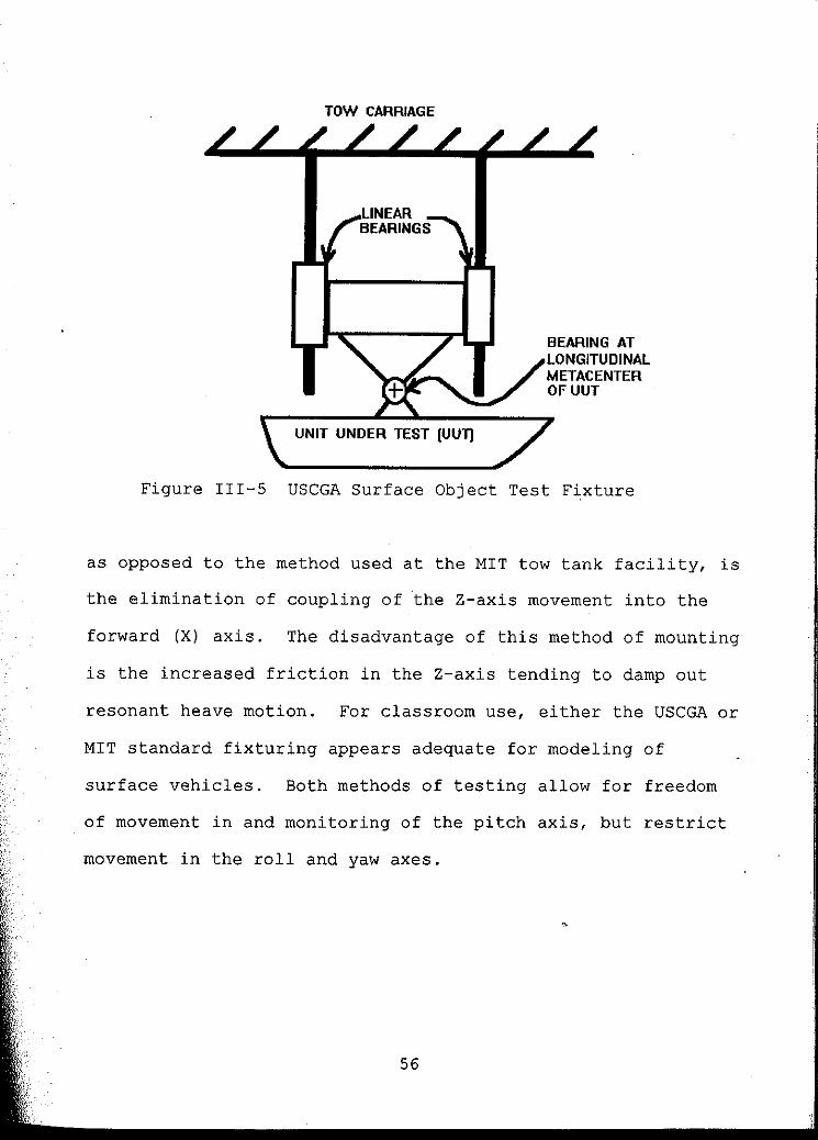
Testing surface objects requires the carriage to be fixed in
all degrees of freedom, except the travel axis, while allowing
the UUT full freedom of movement in and around certain other
axes. Any freedom of movement is then monitored with respect
to the carriage. The USCGA surface object test fixturing, for
classroom purposes, limits freedom of movement to the vertical
axis and pitch angle. This is in keeping with the fixturing,
for classroom use, observed at MIT. The USCGA method of
impiementation is a fixture with two vertical linear bearings
(pillow blocks) along the Z-axis, and a rotational bearing at
the test model's longitudinal metacenter to allow pitching
motion (see Figure III-5). The advantage of this arrangement,
55
TOW CARRIAGE
UNIT UNDER TEST (UUll
BEARING AT LONGITUDINAL METACENTER OFUUT
Figure 111-5 USCGA Surface Object Test Fixture
as opposed to the method used at the MIT tow tank facility, is
the elimination of coupling of the Z-axis movement into the
forward (X) axis. The disadvantage of this method of mounting
is the increased friction in the Z-axis tending to damp out
resonant heave motion. For classroom use, either the USCGA or
MIT standard fix turing appears adequate for modeling of
surface vehicles. Both methods of testing allow for freedom
of movement in and monitoring of the pitch axis, but restrict
movement in the roll and yaw axes.
56

The United States Naval Academy
Location: Anapolis, Maryland
Contact Person: Roger Compton
Phone: 410-293-6423
Small Basin size: Length:
width:
Depth:
36.6 meters
2.4 meters
1.5 meters
(120 feet)
(8.0 feet)
(5.0 feet)
Primary Function: Classroom demonstrations,
midshipmen projects and research.
Maximum Tow Speed: 4.3 mls (14 ft/s, 8.3 knots)
Wavemaker: Air backed, pneumatic dual flapper design.
Hinges on bottom and middle of flapper.
Other Facilities:
Large tow tank 115 x 8.5 x 4.9 meters
Coastal tank 16 x 15 x 0.5 meters
Ballast tank 7.3 x 5.2 x 1.1 meters
Water Tunnel 0.4 m square x 1.5 m long
57

The U.S. Navy is the largest purchaser, owner and operator of
ocean related vehicles and facilities in the United States.
The United States Naval Academy (USNA) is the Navy's education
and training facility for future officers who will procure,
operate and maintain their ships, submarines and facilities of
all kinds. As is logical for support of an organization of
its size and unique responsibility, the Naval Academy is
equipped with a world class hydrodynamics facility, designed
for education of its future officers as well as for evaluation
of and research related to their enormous fleet.
The Naval Academy Hydrodynamics Laboratory (NAHL) is equipped
with four basins and a water tunnel. The 0.4 x 0.4 meter
cross section, 1.5 meters long, high velocity, sealed, see-
through, water tunnel has the capability of observing an
active thruster (propeller) in a pressurized environment.
Internal pressures ranging from 0.2 to 1.4 atmospheres make
the tunnel ideal for observing cavitation effects on
propellers and hydrofoils. The two smaller tanks are not
equipped with towing systems. The smallest tank (7.3 x
5.2 m), referred to as the ballast tank, has a depth of
1:1 meters and is used primarily by students to study
displacement, righting moment, stability, etc. Referred to as •
the coastal tank, the L-shaped 16 x 15 meter wave tank has a
depth which varies from 0.15 to 0.6 meters, and is equipped
with wavemaking capabilities. As its name implies, the tank
58

is used to study coastal effects such as wave propagation and
coastal structures such as breakwaters, jetties, etc.
Only the two largest tanks are equipped with towing
mechanisms. Both of these tanks have wavemaking capability.
The largest tank is 115 meters long, 8.5 meters wide and
nearly 5 meters deep. The carriage is a dual siderail design
powered by a unique cable type drive. The drive cable's
unusual configuration insures the carriage's perpendicularity
to the carriage rails. The tow tank's enhancements include
two carriages, a dual flap wavemaker with programmable wave
profiles and a fiber optic cable link to the control room.
The system is even equipped with simulated wind capability and
is sufficient in size to test very large scale models of
surface vehicles.
The smaller tow tank is the tank of interest to this study,
because it is quite similar in size, capability and expected
usage to the proposed UNH tank. The 36.6 x 2.4 meter tow tank
is referred to in their informational literature as the
"workhorse of the laboratory facilities." The tank is
1.5 meters deep, has no subsurface viewing windows and is sunk
into the floor such that the top of the walls is roughly one
meter above the floor. This arrangement allows for excellent
viewing from above the tank and good accessibility to the
tank. A large classroom area faces this accessible side of
59

the tank. Because of the carriage design, which is
essentially an overhead monorail with an outrigger, this side
of the tank has no rail and as such is safe, completely
accessible and can even be leaned over during testing. Both
ends and the other side of the tank are somewhat less
accessible by a walkway around the tank. The main rail sets
on top of an I-beam, which is in turn supported from the floor
by heavy davits. The davits are located on the less
accessible side of the tank and are spaced about 3 meters
apart. The outrigger rail is mounted on top of the tank wall
on the less accessible side of the tank.
The carriage is relatively large when compared to the MIT
monorail carriage and rolls on roller bearings along a solid
2.5 em diameter steel or stainless steel top rail located
slightly off center and roughly two meters above the tank.
The top rail is held in place by regularly spaced fixtures
which allow the rail to be calibrated both vertically and
horizontally. The weight of the carriage is suspended on four
roller bearings, two forward and two aft, with each pair
arranged in an inverted vee configuration. These bearings
oppose downward forces on the carriage and work with the
outrigger to counter Y-axis and Yaw forces. Idle wheels
• rolling along the under side of the top flange of the overhead
I-beam keep the carriage from jumping the track by countering
any upward forces. The overhead bearings, coupled with the
60

underflange rollers, also appear to be capable of countering
substantial pitch torque. This arrangement, with its
relatively short carriage, does not appear sufficient to
handle the magnitude of pitch torque expected from the
relatively deep UNH tank, however.
The carriage is propelled by a single drive cable, powered by
a 5.6 kW (7.5 hpj DC motor and has a top speed of 4.3 m/s.
Instrumentation observed on the carriage includes an acoustic
unit to measure distance to the water surface (i.e. wave
height) and what appeared to be a standard fixture which
attaches to models of surface vehicles. The fixture allows
motion in both the pitch and yaw axis while measuring both.
Instrumentation on the carriage and power to the carriage is
connected to the control console through a festooned cable
which travels along a separate track, located above and behind
the carriage tracks. The wavemaker and associated software is /
similar to that of the larger wave tank, so testing done in
the smaller tow tank can be scaled up and duplicated in the
larger tank.
61

The Naval Surface Warfare Center, Carderock Div. (NSWC)
Location: Bethesda, Maryland
Contact Person: Tom Warring
Phone: 301-227-4465
Small Tow Tank:
Basin size: Length: 42.6 meters
3.0 meters
1.5 meters
(140 feet)
10 feet)
5.0 feet)
Width:
Depth:
Primary Function: Research and development.
Maximum Tow Speed: 3.1 m/s (10 ft/s, 6.0 knots)
Wavemaker: Inverted pneumatic chamber
other Facilities:
High Speed Basin 905 x 16 x 4.9 meters
Deep Water Basin 575 x 16 x 6.7 meters
Shallow Water Basin 363 x 16 x 3.0 meters
Seakeeping Basin 1l0x 73 x 6-11 meters
Rotating Arm Basin 79 (dia.)x 6.1 meters
Miniature Model Basin 12 x 0.61 x 0.61 meters
Three Water Tunnels
Three Water Channels
30, 61, & 91 cm square
various sizes
vertical Basin and other facilities off site.
•
62
I
The Naval Surface Warfare Center, Carderock Div. (formerly
known as David Taylor Model Basin) is the research,
development and testing arm of the U.S. Navy, and is the
evolved successor of the original hydrodynamic testing basin
mentioned in the historical section at the beginning of this
study. Along with its many other facilities, the Carderock
division houses the longest tow tank in the world, with a
length of 905 meters (2,968 ft), and a top speed of 36 mls
(70 knots). Their long list of facilities includes four
towing basins, one maneuvering and seakeeping basin, a
rotating arm basin, a miniature model basin, three water
tunnels, two water channels on site, several pressure tanks, a
366 meter (1200 ft) deep, natural, vertical basin nearby, a
large cavitation channel in Tennessee and fjord in Alaska for
"
acoustic testing.
What is of particular interest to this study is the 43 meter
long basin, which is similar in size and usage to that of the
UNH tank. Of more general interest to this study is the
various methods of implementing several tow tanks at the same
facility. To put this in a clearer context, NSWC is one of
the most extensive collection of hydrodynamic testing
capability in the world. From this fact one can presume that
if a tow tank or carriage system were implemented
ineffectively, that tank or system would either be reoutfitted
or simply taken out of service. Following this line of
63
, ,
,I' . 'I i
, ,

reasoning, the mere fact that NSWC has a tow tank of similar
size and capability to that of UNH, reinforces its projected
usefulness. Also, the fact that two of the tow tank carriages
were implemented with dominant siderail designs, supports the
viability of that carriage configuration. The three large
towing basins, along with the 43 meter long basin at the
Carderock Div. are reviewed.
The high speed towing basin was not personally observed. It
is 905 meters long and 6.4 meters wide, with a depth of
3.0 meters over one third of its length and 4.9 meters deep
over its remaining length. This tow tank is so long that
correction for the curvature of the earth was taken into
account in leveling its rails. The carriage is large enough
to carry passengers, computers and instrumentation. The
carriage has no umbilical, but receives power through brushes
from overhead cables in a manner similar to that of street
trolleys. The carriage is a basic dual siderail design,
rectangular, approximately symmetrical, and is powered by
dual, electric motor, friction drives.
The shallow water towing basin carriage was personally
observed and is reportedly identical to the deep water towing
basin carriage. The carriage is a dominant siderail type
design. The carriage is driven from an onboard control seat
and is large enough to carry numerous passengers and computers
64

with plenty of room for test equipment. Its shape is
asymmetrical with its weight primarily on the dominant rail.
To move its center of gravity closer to the dominant rail,
much of its heaviest equipment, including its electrohydraulic
pumps and hydraulic drive motors, is actually cantilevered
over the main rail. The large hydraulic motors power the
friction drive wheels on the dominant rail side only.
Perpendicularity of the carriage to the main rail is
maintained by side mounted guide wheels. The idle wheels on
the smaller secondary rail oppose downward vertical forces
only. The dominant rail is steel and is machined on the top
and the two side faces. The rail is fastened to a heavy steel
base plate which is in turn fastened to the concrete. The
rail is shimmed for vertical adjustment and lateral adjusters
attached to the bottom plate are positioned every 0.5 meter
and occasionally closer. The rails appeared clean and rust
free, and onlookers were cautioned not to touch the rails
because their fingerprints would cause rusting.
The 43 meter towing basin, which also was not personally
observed, might be described best as having characteristics
similar to that of an overhead monorail design. The carriage
is suspended from two, steel, accurately machined, H-beam,
• overhead rails. The rails are spaced a little more than a
meter apart and centered over the 3.0 meter wide basin. The
carriage is a square aluminum truss which rolls on rubber
65

faced steel wheels and is powered by twin 3.7 kWelectric
motors and friction drive. The wavemaker for the tank is an
inverted pneumatic chamber type and was the prototype after
which the wavemakers in the other tanks were modeled.
•
66

The Naval Undersea Warfare Center (NUWC)
Location: Newport, Rhode Island
Contact Person: Dick Philips
Phone: 401-841-6036
Basin size: Length: 18.3 meters
Width: 0.9 meters
Depth: 0.9 meters
(60 feet)
(3.0 feet)
(3.0 feet)
Primary Function: Research and development.
Maximum Tow Speed: 3.0 m/s (10 ft/s, 5.8 knots)
Wavemaker: None observed.
Other Facilities: Visitation was limited to the tow tank .
•
67

The Naval Undersea Warfare center is one of the U.S. Navy's
secure research and development centers. The Center houses
other facilities, however the tow tank was the only facility
observed. The tank itself was 18.3 meters long, with a cross
section of 0.9 meters square and is raised approximately one
meter above the floor. The elevated height affords excellent
visibility because the entire length of either wall is made up
of sheets of safety glass. Two Plexiglas bottom windows also
allow viewing from the bottom. The tank is somewhat unique in
that it is designed for, and usually filled with, salt water.
The 1.2 meter wide, 0.9 meter long, aluminum frame carriage
rolls along two 5.1 cm diameter round steel rails mounted atop
the two sidewalls of the tank. It rolls on four linear
bearings, often referred to as pillow blocks. Unlike rail
systems where the carriage wheels roll on top of the rails,
the linear bearings attach the carriage to the rails and
restrain it in all axes except for linear movement along the
X-axis. Test objects are either bolted to the aluminum frame
or attached with I-beam flange clamps made by Klinger
Scientific. The carriage has a minimum clearance of 14 cm
above the surface of the water.
The carriage is propelled by two 3.2 mID diameter steel cables.
The drive system is powered by a 1.1 kW motor with what
68
i ,I , !
I ~

. i
,
, I !
1,1
1
.1
., .
, !
:,1 '
appeared to be an open loop controller. A carriage
speedometer accurate to 0.1 ft/s (0.003 m/s) displayed the
actual carriage speed. Power, signal and one air pressure
tube were laced together and attached to the carriage by
festooning them from a cable track. Special test capabilities
included the use of particles and/or flouresene dye and lasers
to observe fluid flow.
•
69

!. I
!
i
••• 1
: I
The Offshore Model Basin (OMB)
Location: Escondido, California
Contact Person: Art Lynch
Phone: 619-737-8850
Basin size: Length: 90 meters ( 295 feet)
Width: 14.6 meters 48 feet)
Depth: 4.6 meters 15 feet)
Primary Function: Commercial research and development.
Maximum Tow Speed: 6.1 m/s (18 ft/s, 10.7 knots)
Wavemaker: Water backed, hydraulically driven,
bottom hinged, flapper type.
other Facilities:
Coastal/Hydraulic basin 17 x 49 x 0.6 meters
Salt water tunnel 0.6 meter dia. (under construction)
70

The towing basin at OMB is not particularly comparable to the
tank at UNH because of its size and location. However, having
had the opportunity to visit OMB, information gained from the
visit merits inclusion.
The basin itself is very large. According to their
literature, the basin is "the largest commercial towing and
seakeeping facility in North America". The top of the tank
walls are about a meter above the surrounding concrete floor
allowing for easy viewing over the walls. Windows in the tank
wall allow for viewing at and beneath the water's surface. A
5.8 meter square, 4.4 meter deep pit in the center of the
basin affords the possibility of viewing a test object from
below, as well as providing for deeper hydrostatic testing.
The tank had a wavemaker at one end and a sloping beach
covered with stainless steel shreds at the other.
The towing carriage is a rectangular truss which spans the
14.6 meter wide basin, but is only 3 to 4 meters long. The
carriage, loaded with its drive motors, walkways, fix turing
and instrumentation, has a reported total mass of about
4500 kg (10,000 lbm). Special fixturing on the bottom of the
carriage, referred to as a rotating subcarriage, allows a test
object to be rotated to any angle in the tank~s X-Y plane
without refixturing. Another fixturing mechanism allows for
71

.......... ----------------------
, . II· ~ II .
t . ,
II
!t
computer controlled, Z-axis and Y-axis planar motion of a test
object.
The carriage system is a classic double siderail design. The
carriage rolls on steel wheels on steel rails mounted on top
of each of the tank's concrete sidewalls. It is restrained
from movement in the Y-axis by steel wheels on both sides of
one rail, fore and aft of the carriage, with a separation of
about 5 meters. Because the carriage is essentially a long
narrow truss extending from the rail, the relatively closely
spaced guide wheels cannot, by themselves, control the
carriage's perpendicularity to the rail. Instead, the
perpendicularity is maintained by commanding the drive wheels
on either end of the carriage to turn at precisely the same
velocity. The guide wheels insure perpendicularity at start
up, and the drive wheel velocity control maintains that
perpendicularity as the carriage accelerates and travels the
length of the tank. Although the system was not operational
at the time of the visit, it reportedly works quite well.
The carriage is powered by dual, onboard, matched, 500 volt,
22 kW, DC motors. The steel to steel friction drive wheels
are geared to the motors by a cogged flat belt and pulley
system. A thin coating of rust was observed on both rails and
all of the steel wheels. A wire brush, mounted in front of
the drive wheels, served to clean any roughness from the rail
72

but did not polish the rail's surface. As explained, the thin
oxidation layer did not pose a maintenance problem, but did
increase the coefficient of friction to the steel drive wheel.
Without some oxidation, the wheels could slip during rapid
acceleration.
Electrical power and instrument signals are fed to and from
the carriage through long cables festooned along cable troughs
attached to the ceiling. The power and signal cables extend
from opposite ends of the tank and on separate cable tracks to
minimize electrical crosstalk. Low voltage signals from
instrumentation, such as strain gauges, are not pre-amplified
on the carriage. The signals are instead amplified in a
control room, over 140 cable meters away. The amplifiers
serve both as calibrating amplifiers and as signal
conditioners. Some signal conditioning to reject 60 Hz noise
is reportedly required.
The tank's facilities also include a second, independent, non
powered carriage assembly which rolls along a separate set of
floor mounted rails. The carriage structure straddles the
tank and the primary carriage. This structure also has a
rotating subcarriage with structural projections which extend
to the bottom of the tank. This carriage is evidently used to
moor objects while testing them in various sea states.
73

CHAPTER IV
DESIGN ALTERNATIVES FOR THE UNH TANK
Design Concept Alternatives for the Carriage
The following design concepts were considered for the carriage
system:
1. Dual Siderail, Cross-Tank Carriage
2. Overhead Monorail Carriage with Outrigger
3. Dominant Siderail with Lightweight Secondary Rail
The following sections describe the major aspects of these
concepts.
Dual Siderail, Cross-Tank Carriage -- The majority of tow tank
carriages in use in the United states today are dual siderail
designs. For purposes of discussion, dual siderail carriages
are more or less symmetrical about the X-Z plane. Their drive
systems are designed to drive each side of the carriage
equally, thereby sharing the load. Carriages of this type
generally have guide wheels, but they are not intended to
withstand large yaw torques applied to the rails. Of the •
facilities visited, USCGA, WHOI, URI, OMB and USNA (large
tank) all had this type of carriage design. The carriages in
this type of design are large, usually with a rectangular
74

CHAPTER IV
DESIGN ALTERNATIVES FOR THE UNH 'tANK
Design Concept Alternatives for the Carriage
The following design concepts were considered for the carriage
system:
1 . . Dual Siderail, Cross-Tank Carriage
2. Overhead Monorail Carriage with Outrigger
3. Dominant Siderail with Lightweight Secondary Rail
The following sections describe the major aspects of these
concepts.
Dual Siderail, Cross-Tank Carriage -- The mqjority of tow tank ,
carriages in use in the United States today are dual siderail
designs. For purposes of discussion, dual siderail carriages
are more or less symmetrical about the X-Z plane. Their drive
systems are designed to drive each side of the carriage
equally, thereby sharing the load. Carriages of this type
generally have guide wheels, but they are not intended to
withstand large yaw torques applied to the rails. Of the
facilities visited, USCGA, WHOI, URI, OMB and USNA (large
tank) all had this type of carriage design. The carriages in
this type of design are large, usually with a rectangular
74

structure and wide enough to span the tank. The carriages
normally roll along the top of matching rails mounted atop
each side of the tank. Propulsion of the carriage is usually
accomplished by pulling it with steel cables, or by using
onboard friction drive motors which use the carriage's own
weight for traction. Test objects are attached below the
carriage, usually on struts extending from the center of the
carriage, and are dragged along with the carriage as it rolls
atop the rails. The dominating design characteristic of this
type of carriage is that it is large. A carriage of this
design for the UNH tank would be more than 4 meters wide,
3 meters long and strong enough to safely support the weight
of at least four large adults at its midpoint since it would
be expected to serve as both a work platform and a bridge. As
a direct consequence of its size and strength, it must have
considerable mass, thus requiring heavy, durable rails on each . ~
side and a powerful drive system for even moderate towing
speeds.
Conventionally, rails mounted atop the &ides of the tank which
carry such a load are constructed of steel. URI, however, I successfully implemented such a system with rubber wheels I rolling along an aluminum track. In either case, the track
material presents a potential thermal expansion mismatch
between the track and the concrete wall. All such rails
observed had some type of expansion joints. These joints are
75
discontinuities in the rail which must be properly engineered
so as not to degrade the smooth rolling performance of the
carriage. To insure a smooth rolling platform, the rails must
be as close to perfectly level as can be achieved. This
usually requires some form of adjusters which allow for
recalibration to accommodate tank and building settling.
Because of the size, weight bearing capability and expansion
joints of these siderails, the rail mounting system is
typically complex. The machining requirements for the
fixturing could easily match or exceed the cost of the rails
themselves.
The shear mass of the dual siderail carriage does offer a
slight advantage in stability of holding a small UUT under
tow. The massive spanning structures have resonances at lower
frequencies than do lighter structures. The carriage thus
acts like a low pass filter, in that it would appear to a UUT
to be a stable or rigid mount at frequencies above the
carriages highest resonant frequency. Unfortunately, for
tests involving low frequencies (such as a large UUT on a long
support arm) resonance might still be a problem. Given the
cross section and depth of the UNH tank, low frequency
resonance is a potential concern, and structural rigidity may
prove more effective than shear mass for implementing a stable
platform. Also, if the carriage is strong and rigid enough,
mass can be arbitrarily added if needed.
76

r
Assuming compliance with stability requirements, the carriage
system must also remain rigid with respect to all forces
applied to it by the UUT and the power train. It must
maintain this rigidity while accurately moving along the
X-axis. Accuracy, in this case, refers to negligible Y-axis,
Z-axis, Roll, Pitch and Yaw motion while traveling along the
X-axis at a consistent and accurately monitored velocity. To
accomplish this, the carriage must oppose all applied forces
with minimal distortion of the carriage and without leavi~g
its rails. The carriage system must also withstand the
tremendous forces of an emergency stop or a jammed rail stop
without derailing or sustaining significant damage to itself
or to the supporting tank. The requirements for immunity to
damage and derailment and for structural rigidity tend to
increase carriage weight.
For testing of objects towed along the surface of the tank or
with less than a half meter, submersion, the largest force
applied to the carriage is along the X-axis. This force is
opposed through the drive system, which has generally proved
successful on dual siderail type designs. For submerged
object testing, the UUT must be suspended at some fixed
distance below the carriage while the UUT is propelled through
the water. Its movement through the water generates a drag
force, resulting in a substantial pitch torque. For example,
77

a 1.0 meter sphere towed in the center of the tanks water
column, about 1.7 meters below the carriage, at a forward
velocity of 2.6 m/sec (5.0 knots) would develop a drag force
of over 1300 Newtons with a resulting pitch torque of about
2200 N-m. In the dual siderail designs observed, the only
force opposing the pitch torque is the weight of the carriage
multiplied by its distance from the center of gravity to the
front wheels of the carriage. For a 2.0 meter long carriage,
the carriage needs a mass of 225 kg to keep from tipping due
to the applied pitch torque. The same object towed near the
bottom would nearly double the required mass. The large
required carriage mass is detrimental to top end performance
of the system.
Both vertical motion due to lifting forces on a UUT and pitch
forces described in the previous paragraph are countered using
the weight of the carriage. Roll forces, produced by forces
acting on the UUT along the y-axis at some distance below the
carriage, are also countered using weight of the carriage.
The roll forces tend riot to be a problem, however, because the
forces on the UUT perpendicular to the direction of travel
tend to be much smaller than the forward drag forces. Thus
the roll torques are much smaller than the pitch torques. In
addition, the carriage is usually wider than it is long (the
UNH carriage would have to be at least 4 meters wide), thus a
78
carriage of some fixed mass can typically handle more roll
torque than pitch torque without tipping.
In a double siderail design, yaw forces are kept low by
building symmetry into the drive system. Cable driven systems
are therefore usually driven by a cable on each side (such as
that of USCGA) while friction drive systems (such as that of
URI) attempt to match drive speed on both sides of the tank.
By doing this, yaw and y-axis forces acting on the carriage
are minimized under normal operating conditions. Remaining
yaw and y-axis forces are usually the result of asymmetrical
test objects or a UUT with a lifting surfaces. A lifting
surface deliberately mounted at an angle of attack will result
in forces on the UUT other than forward drag. Most tests
involving lifting surfaces, however, are not particularly
sensitive with regard to the direction of the lift and can be
mounted in an orientation which best suits the towing
carriage. Some test objects exhibiting large nonsymetrical
forces cannot be optimally reoriented. The test object likely
to apply the largest, asymmetrical force to the carriage in
the X-z plane, is a skewed boom configuration. To counter
these forces and to prevent the carriage from inadvertently
rolling off the track, some form of guide wheels are required.
The USCGA and WHOI carriages both use side mounted wheels, in
front and rear of the carriage, rolling along both sides of
one of the siderails. URI mounted wheels to roll along the
79
~I ,i ,I
,I I !
:1 , I I
i 1 1
I . I

inside of both rails. Placing the guide wheels on both sides
of one rail appears to be the better method. Calibrating the
thickness of one rail is significantly easier and more
accurate than calibrating the separation of both rails. Also,
in the event of a sudden stop due to collision or jamming of
one rail, racking of a carriage could cause large secondary
forces perpendicular to the tank walls in a system such as
that of URI. This could aggravate cracking of the tank walls,
especially in the weak area containing the side windows.
The primary design advantage of the dual siderail design is in
driving both sides of the carriage equally to keep the
carriage squarely aligned with the tracks. The large forces
along the X-axis are distributed equally into each side of the
symmetrical drive system. Such forces are therefore not
opposed as a yaw torque in either or both rails. Of all
carriage drive systems observed with dual siderail designs,
only the unique cable drive system on the large towing
carriage system at the USNA appeared completely successful.
All other systems ended up canceling mismatches in symmetry of
drives with the previously mentioned guide wheels keyed to the
sides of the rails. In effect, most dual siderail designs
acted somewhat like dominant siderail designs.
Should the dual siderail design have been selected as the
optimum configuration for the tank, -tentative conclusions
80

favored either a cable drive system, such as that at the USNA,
or dual, matched torque, friction drive. A dual, matched
torque, friction drive could be implemented using two
identical DC motors wired in series and connected to a single
controller. This configuration would still require guide
wheels, but forces along the X-axis should be equally
distributed between the two motors regardless of their speed.
No such implementation of the latter technique was ever
identified in the research.
Overhead Monorail Carriage with Outrigger -- An overhead
monorail carriage is basically a carriage which hangs from a
rail over the center of the tow tank. A true monorail
carriage would have limited applications because it could not
cancel applied roll forces. For this reason the observed
monorail type carriages have some form of outrigger which
cancels roll. The best example of such a carriage was
observed at MIT. The monorail design has several advantages
over the dual siderail system. First, and most important, it
is far safer than the dual siderail system. The active rail
(the rail with the drive system) is located over the
centerline of the tow tank where an operator or observer
cannot easily come in contact with it during normal operation.
Because the active' rail is located above the cent~r of the
tank, any drive cable or strap must also be located above the
center of the tank. In the event of failure, a snapped cable
81

above the center of the basin is less likely to cause injury
to observers along the sides of the tank.
The monorail carriage does require a second, passive (non
powered) rail to cancel roll forces, as described in the
evaluation of the MIT tow tank. This rail, however, sees much
smaller forces than the overhead rail or either rail of the
dual siderail design, and it may be placed in a safer position
such as along the inside of the tank wall. This is the case
with the MIT outrigger rail. Because of their overhead
monorail type carriages, both the MIT tow tank and the USNA
smaller tow tank have one side completely free of rails, which
is safe for observers to stand near and even lean on during
the operation of the carriage.
The monorail carriage offers the advantage of inherently
lighter weight, which also provides for added safety and
improved performance. The added safety comes from the fact
that the significantly reduoed moving mass results in less
energy to dissipate during an emergency stop or jam, or a
reduced stopping distance with the same emergency stop forces.
The improved performance, primarily in the test speed, results
from the reduced mass which is more easily accelerated. The
inherently lower mass of the monorail carriage comes as a
result of transferring the vertical structural support
requirements to a stationary overhead structure. In a dual
82
•
......
siderail design, forces from the DDT are imposed upon the
cross-tank carriage structure which in turn transfers those
forces, via the cross-tank structure's rigidity, to the rails.
The overhead monorail requires no such intermediate structure
between it and the rail.
The optimum location in the tank for testing various objects
is almost always along the centerline of the tank. The
combined forces of weight, lift and the potentially large
pitch forces must be opposed by some structure which transmits
these forces to the tank's concrete wall or the foundation of
the building housing the tank. The overhead monorail
structure rides along a stationary structure which transmits
the forces to the foundation. For a dual siderail design, the
cross-tank carriage serves as that structure. In a dual
siderail design, that structure must travel with the DDT. If
cable drive is used in a monorail design, cable tension forces
are opposed by compression of the overhead structure and drag
forces of the DDT along the X-axis. Hence, they are not
directly transmitted to the tank walls. Buoyancy, weight of I the DDT, any yaw torque, as well as the potentially large 1
pitch torques are almost entirely canceled within the overhead
support beam. The relatively small Y-axis forces are coupled
into the roll axis and they, along with any roll torque, are
opposed by the overhead beam and the roll rail (outrigger
rail). The largest instantaneous forces, emergency stop or
83

jamming forces, are transmitted through the overhead beam to
the support system and need not be dissipated in the tank 1
walls. The overhead structure may transmit the energy
absorbed from such a stop into the building foundation or
structure, or the tank walls if it is attached to those walls.
The forces transmitted to the overhead structure may be
redistributed over a larger area or into specific structural
attachments to absorb such shock forces.
An additional benefit of the overhead structure is that any
thermal expansion mismatch between the concrete walls of the
tank and the attached rail may be eliminated. The absence of
the need for expansion joints reduces the complexity of the
rail and mounting of the rail. It may also reduce cost and
difficulty of calibration of the rail.
All of the tow tanks observed sacrificed useable length of the
tank to accommodate wavemakers, wave absorbers and/or the
towing carriage length. Towing carriages, in most cases, were
kept short thus lowering the cost of the carriage and
increasing the usable length of the tank. The UNH tow tank is
constructed in a building with a high ceiling and substantial
clearance on all sides End clearance could be used to extend
the overhead carriage rail, which would allow for a longer
carriage without sacrificing useable tow tank length. An
overhead monorail placed more than two meters above the floor
84

could be extended well beyond the ends of the tank without
obstructing walkways or otherwise reducing useable floor
space. Allowing ·for a longer carriage significantly reduces
forces on the rail which result from pitch torque. With an
extended overhead rail, a longer carriage would not
necessarily reduce the useable length of the tank. Also, such
an extended carriage would still be much lighter than a cross
tank structural carriage.
One implementation of such a monorail design for the UNH tank
would be an overhead stainless steel pipe rail suspended from
a supporting beam with a second rail, for the carriages
outrigger, attached to the inside wall near the top of the
tank. This design would be quite similar to the MIT carriage
design described earlier. The supporting beam could be a 30 x
15 cm (12 x 6 in) steel box beam extending the full length of
the tow tank. Th~ box beam would in turn be supported by four
cross beams (I-beams) located at both ends and about
ten meters from either end of the tank. The approximate cost
of such a support structure and rails for this design was
estimated at about $8700, assuming assembly cost at 50% of the
cost of the steel. A comparable rough estimate of the cost of
constructing dual siderails was around $8100. Although the
cost of the steel construction and the steel rails themselves
was lower (about $4500), the cost of rail adjustment
assemblies to support and calibrate the stronger, heavier
85

rails was conservatively estimated at $6/meter, which brought
the overall cost up to the estimated $8100. Once the cost of
a larger structural carriage for the dual siderail design is
factored in, the cost for the overhead monorail system is
quite comparable and possibly lower. in cost than the dual
siderail design.
Disadvantages of the overhead monorail carriage design lie in
its obstruction of overhead clearance and potential
instabilities and resonances in the overhead structure. The
design considered above allpws for about twenty meters of
unsupported length of the overhead beam in the center section
o~ the tank. Thus the center 20 meters would be almost
unobstructed except for the beam. None-the-less, the overhead
beam still remains as an obvious obstruction.
Feasibility of the box beam structure was examined for beam
sag and deflection under carriage load. The findings were
that the 2.6 metric ton box beam could sag as much as 5.5 cm
in the center of the tank. This permanent sag could be
calibrated out by extending the rail calibration standoffs on
the rest of the rail. The potential for a 0.7 cm additional
sag as a result of a 100 kg carriage moving along the rail
could also be compensated by calibrating the rail with the
carriage located at each adjustment point as it is calibrated.
Resonant frequencies of the box beam structure, and the
86

potential instabilities of the carriage and UUT moving along
the beam under load, were not investigated in any depth.
Dominant Siderail With Lightweight Secondary Rail -- A third
design considered for the UNH tank, was a hybrid of the
overhead monorail and the dual siderail design. Although no
similar carriage design was identified during the research
phase, the design seemed to be a logical compromise between
the desire for the overhead clearance afforded by the dual
siderail design and the ability of the overhead monorail to
contend with the large pitch forces caused by submerged
objects towed in the relatively deep UNH tank. As
construction of the UNH carriage neared completion, however, a
similar carriage design was identified and observed at NSWC.
In the NSWC design a large, active, main rail sets atop one
side of the tank while a smaller passive rail, supports a
large outrigger which spans the entire width of the tank.
"Active rail" refers to the fact that drive power is applied
along this rail, whereas "passive rail" refers to a rail with
only free rolling wheels and no propulsion along this rail.
Wheels or bearings around the heavier main rail counter all
forces applied to the carriage except roll and a portion of
the vertical forces. Wheels or bearings on the secondary rail
act only in the vertical or Z direction.
87 J

Since the dominant siderail design still requires a rail on
each side of the tank, safety is not as good as the overhead
monorail design. However, since only one rail is driven, only
one side of the tank need have drive wheels or a cable which
could snap. Additionally, since only vertical forces are
imparted on the passive secondary rail, this rail may be
mounted on the inside wall below the top of the tank so that
at least one side is relatively safe for observers. The
observation side of a tank, with such a subtended rail, could
even be safely leaned on by observers during operation.
Safety would be assured as long as nothing was allowed to
extend beyond or hang over the inside wall of the tank.
The cross-tank structure for a dominant siderail design is not
necessarily symmetrical. In fact, the 9.3 m/s (18 knot)
carriage observed at the Carderock Division of NSWC actually
cantilevers some of the carriage's heavier onboard equipment
across the dominant rail to further reduce the forces on the
secondary rail. Since the secondary rail is only needed to
support a lightweight outrigger for canceling minimal roll and
lift forces, the cross-tank structure need not be as massive
as a symmetrical dual siderail design. with a lighter cross-
tank structure, the performance compromise between maximum
speed and c'arriage mass may be improved over that of the
conventional dual siderail design. The single siderail,
however, cannot quite match the performance of the overhead
, ' , 88
monorail. This degraded performance is further compromised by
the fact that since this carriage looks and acts similar to a
dual siderail carriage, it is usually expected to double as a
bridge and work platform. A potential engineering solution to
the tradeoff between the versatile work platform and the
degraded carriage performance would be to provide a detachable
bridge structure which could be quickly and easily removed and
replaced with a light weight outrigger for tests requiring
maximum speed. Depending on>the degree of accuracy which can
be calibrated into the main rail, the possibility exists that
the outrigger may even be eliminated in those tests which
result in little or no roll forces. Examples of such tests
include small models of surface vehicles and stable,
symmetrical, neutrally buoyant, submerged objects in proper
alignment with the main rail.
Countering of the various forces varies with the type of test
and fixturing used"but can be analyzed in a manner similar to
the previous carriage types. All X-axis forces, including the
shock of emergency stop or jamming, may be transmitted into
the massive siderail and are in turned distributed along the
tank wall. The smaller horizontal (Y-axis) forces are
countered directly from the main rail and vertical (Z-axis)
forces are coupled into the roll axis and opposed by both the
main rail and the roll rail. Pitch and yaw forces, however,
are handled differently than either of the previous designs.
89

Submerged objects suspended in the center of the tank, that
would have generated a large pitch torque only in the monorail
design, create both pitch and yaw moments. Interestingly, the
normal operating yaw torque is larger than that of the dual
siderail design. However, the emergency stop or jamming
forces would be smaller than those of the dual siderail design
because of the potentially lower mass of the carriage. In
either case, all pitch and yaw torques are transmitted to the
main rail which is intimately coupled to one wall of the tank.
To optimally incorporate this design into the UNH tank, the
main rail should be attached to the windowless side of the
tank to minimize potential damage or cracking in the concrete
walls from these forces.
concept Selection
Meetings were held and the various design concepts were
reviewed by fa,::ulty, staff and students of the center for
Ocean Engineering at UNH. Presentations favored a monorail
desigh similar to that of MIT for reasons of performance and
versatility. Concern was expressed, however, that many
experiments in the foreseeable future, like that of oil
containment barrier testing, would require one or two
passengers aboard the carriage to manually manipulate the unit
under test or its environment (such as manually dumping oil
spill simulation contaminants ahead of a containment barrier) .
90

Overhead structural requirements for the monorail made
designing it for safe passenger transport impractical. By
this default, the overhead monorail design was rejected.
At the time the decision on design concept was being rendered,
no dominant siderail design had been identified in the
research. Thus it was considered to be a higher risk design
than the more conventional dual siderail design. Observations
of stability problems in various existing dual siderail
designs, however, showed them to actually act more like
dominant siderail systems. A small model demonstrating its
feasibility, along with potential cost and safety advantages
of the dominant siderail design, eventually led to the
acceptance of the dominant siderail concept.
Drive System Alternatives
Much of the information for intelligent selection of a drive
system came ~rom first hand observations acquired as a result
of visits to the various towing facilities. Discussion of the
selection of a drive system is presented in this study as a
logical follow up to the selection of a carriage system. What
the reader must keep in mind is the interaction between drive
system, rail system, final carriage design, as well as
electrical power restrictions and design conflicts with an
ongoing wavemaker design and installation. Carriage, rail and
drive systems were interactively evaluated throughout the
91

design and construction phase, so the exact final drive design
was not solidified until the carriage was actually on its
rails.
Key engineering parameters considered in selecting the
fundamental drive design were load and speed requirements
identified in the initial system design specifications, cost,
safety, electromagnetic noise, ease of operation and
modularity for ease of modification. Key inputs resulting
from the various visitations were as follows:
Friction drive wheel slippage potential problem expressed by URI and OMB.
Corrosion of lubricated steel rails from fingerprints as a result of being touched expressed by USNA, USCGA and NSWC.
Very low maintenance, in spite of heavy use, was expressed by the operator at MIT. In fact, the statement was made that there had been no significant maintenance on the stainless steel tubular rails or the harrdened steel strap drive in the many years since their installation.
Potential electromagnetic noise problems, especially around 60 Hz, expressed by WHOI and OMB. Engineers at WHOI found particular problems with electromagnetic interference when trying to calibrate modern electromagnetic type ocean current meters, such as the S-4 models made by InterOcean Systems, Inc. Concerns were also expressed regarding electrical currents created by dissimilar metals in contact with the water.
Mechanical velocity noise, caused by the unfolding of various power and signal umbilicals, was expressed as a concern by MIT and USCGA. MIT minimized the noise by designing the .umbilicals with minimum mass and friction and tested to ascertain its impact on performance. The resulting velocity noise was confirmed, its frequency at speed identified and confirmed to be a non-problem in
92

most cases. The USCGA carriage had only signal cables but experienced enough problems and/or concerns to reoutfit the carriage with an onboard uninterruptable power supply and data logger. As a result, the carriage has no umbilicals during operation. Comments were quite positive regarding the success of this reconfiguration.
Safety concerns, about keeping observers clear of the operating towing carriages and especially clear of live drive cables (wire ropes), were expressed by most facilities. Notable exceptions were MIT and the smaller classroom facility at USNA, because of their inherently safe overhead monorail designs. Also by WHOI because of its size and limited access during operation.
Notable in all interviews was the immediate availability of information concerning basin shape (length, width, depth, windows, etc.) and maximum speed. "Brag speed", as I choose to refer to it, is the maximum speed achievable by the carriage with no reference to restrictions or loading. Horsepower and type of drive were also commonly available on request.
Most notably absent as available information was carriage weight. Weight or mass of the carriage is, important in ascertaining frequency response, acceleration time, system stability with a given load, etc. Maximum towing capacity, positioning accuracy and velocity accuracy were also unavailable in most cases.
Four fundamental drive designs were considered for the
selected dominant siderail design. Option one was a linear
induction motor running along the entire length of the
dominant rail. Option two was a geared (rack and pinion) or
cogged drive. Option three was a more conventional friction
drive. Option four was a cable, belt or strap drive.
The linear induction motor offered the possibility of very
smooth operation with a broad range of thrust and speed
capability. Linear induction drive is accomplished by placing
93

a linear induction field, similar to the fields of an
• induction AC motor, along the entire length of the drive rail.
A reactive element, similar to the rotor of the AC motor,
would be attached to the carriage and held at a small fixed
distance from the induction field by the same accurate rail
upon which the carriage rides. cost was not prohibitive but
was a definite disadvantage. Precision positioning
requirements between rail and linear motor armature, serious
concerns about corrosion of the motor's exposed ferrous core,
the potential for large amounts of ~lectromagnetic noise,
along with the high cost eliminated this option.
The second option was a geared or cogged type of drive.
Methods of implementation and approximate costs were reviewed
by investigating various aftermarket stair climbing systems
which convert existing or new construction stair cases for
handicap access. These systems had similar power and force
requirements, but maximum speed and smoothness of operation
needed to be addressed. The geared or cogged type of drive
was eliminated, however, mostly by comparison to the more
conventional friction drive. Any system which could be built
with a geared drive could be matched at a lower cost by a
similar configuration of friction drive which would not be
subject to gear noise. The elimination of slip guaranteed by
gear or cog teeth is desirable but not necessary.
94

Friction drive, the third option, is the type of drive system
used for the URI, WHOI, NSWC and OMB tow tanks. It appeared
to be reasonably simple to design and could be implemented at
a reasonable cost. The drive wheels, in most cases, roll
along the top of the rails and drive the carriage in much the
same way as the drive wheels of a car. The propulsion force
applied to the carriage is a result of torque applied to the
drive wheels and friction between the rails and the wheel. If
too much torque is applied to the wheels, however, the
friction force may be overcome resulting in wheel slippage.
Exactly how much of a problem wheel slippage would be is
unknown, but the problem might be overcome by having the drive
wheels pinch the rail instead of depending upon carriage
weight to provide the necessary force on the wheels to provide
sufficient traction for acceleration. The disadvantages of
the friction drive system involved the fact that the motor,
gearing system and probably the controller have to be onboard
the carriage. In addition, the carriage would have to be
further burdened with either a large power umbilical or a
heavy battery bank with sufficient energy to power the
carriage for several sequential runs. A heavy umbilical is
'undesirable for reasons of electromagnetic noise as well as
velocity noise as it unfolds and trails the carriage. Battery
power appeared reasonaQle if the carriage only operated a
limited number of cycles per day. Aside from the potential
hazards, batteries were perceived as a definite maintenance
95

burden and a potential source of frustration to the user who
may run out of batteries and lose valuable hours of testing
while waiting for them to charge. These disadvantages, plus
the potential for electromagnetic noise from the onboard motor
and controller, caused the final engineering decision to lean
in favor of a cable type drive.
A cable (wire rope) type drive was selected to be the optimum
choice. Options such as strap or belt drive were
investigated, but no ready source could be identified for that
type of drive so the search was discontinued. Standard wire
rope, along with associated sheaves and fixturing were found
to be readily available. The only additional weight imposed
on the carriage from such a system was basically the cable
itself. This type of drive proved to be modular and not
particularly dependent upon where the motor and gearing were
located. Since the cable carried no electrical power and the
motor could be located away from the carriage, electrical
noise was considered minimal. The identified disadvantages
were cable stretch, which could result in system resonance,
and the potential hazard of a snapping cable. System
resonance from the carriage on a taut cable with significant
wheel friction (mass on a spring with friction) appeared to
emulate a classic second order system and was not considered
to be a big problem. The hazards of cable snap were limited
because the chosen carriage system was a dominant siderail
96
,

design. With only one side driven, the single required drive
cable could be located opposite the viewing side of the tank
and enclosed over most, if not all, of its length. Note that,
at the time of this decision, a detailed cable drive design
had not yet been generated, however.
Drive System Power Requirements & Gear Ratios
Although the exact drive requirements of the towing carriage
are varied and unpredictable, most applications can be
accommodated provided that certain capabilities are met.
These capabilities include maximum velocity, ability to
control forward and reverse velocity and velocity profile,
sufficient torque to handle the maximum towing force required,
and total drive power requirements. In general, the greater
the towing power and maximum forward speed, the greater the
likelihood of covering all possible applications.
One solution is to take the maximum expected towing speed,
multiplied by the maximum expected towing force, to get the
maximum drive power requirements. From the carriage power
requirements examined previously, a maximum towing force of
3100 Newtons (700 lbf), with a desired maximum speed of
5.2 mls (10 knots) and a transmission efficiency of 60%, would
require a 27 kW (36 hpj motor. This overly simplistic
approach to the design, however, greatly exaggerates the
97

actual power requirements. Previous calculations showed that
the actual maximum power required, assuming 60% efficiency,
for any of the anticipated loads, was only about 6.7 kW
(8.9 hp). The simplistic implementation described is similar
to designing a heavy truck to accelerate up a steep hill in
the same gear that it travels at high speed on level road. By
allowing for some adjustability of gear ratio, a fixed drive
motor power can provide a much broader range of performance.
Figure IV-1 depicts the maximum carriage velocity versus
cable tension for 6.6, 7.S and 11 kW (7.S, 10 & IS hpj motors.
The graphs assume ideal drive ratios and a conservative 60%
efficiency. The points identified on the graph represent
loads and speeds identified in the design constraints. The
maximum towing force of 3100 Newtons at 1.3 mls and the
1.0 meter submerged sphere towed at 2.6 mls with a resulting
force of 12S0 Newtons both fall under the 7.S kW line, but
require different gear ratios to do so. The design conclusion
from this analysis was to construct the drive with a 7.S kW
(10 hpj motor and to allow for changeable gear ratios.
98
Zl!

9.0
8.0
7.0
" 6.0 .. ~ * 5.0 ::. .6 4.0 .~ " ~ 3.0
2.0
1.0
0.0 0 400
Figure IV-l
Forward Velocity vs Propulsion Force Assuming 60% Efficiency
800 1200 1600 2000 2400
Propulsion Force in Newtons
2800 3200
Carriage Velocity vs Propulsion Force
99

Motor and Controller Alternatives
Chronologically, the final decision of what type of motor and \ controller to use came very late in the design and
construction of the system. Some type of electric motor drive
was basically assumed to be the most appropriate choice and
thus only electric motors were considered. At the time of the
drive design, no other type of drive system had been observed.
Consequently, engineering tradeoffs and evaluations in this
study are confined to pulse width modulated (PWM) DC, inverter
type AC, and vector type AC motor and controller systems.
Having subsequently observed the smooth operation of the
impressive hydraulic motor driven carriage at NSWC, my
recommendation would be to at least review such a drive in
future applications.
PWM DC motor and controller is the conventional method of
controlling loads over a broad range of speeds with maximum
torque requirements at the lowest speeds. 3-phase AC power is
rectified to provide the necessary DC voltage to run the DC
motor and the controller simply chops or modulates it to
provide variable speed and torque from the motor. The recent
proliferation of low cost, reliable AC motor controllers,
coupled with the low cost and reliability of AC induction
motors, has resulted in AC motor/controllers which cost less
than DC motor/controllers and perform most of the same
functions. Since AC motor/controller combinations were found
100
14
'I.
·-i
I

adequate for the drive needs of the carriage system, DC motors
were eliminated for reasons of cost and availability.
Inverter type AC motor controllers basically apply a variable
frequency, three phase, effective sine wave to the AC motor.
The motor's rotational speed is dictated by that frequency.
For example, assuming minimal load, a three phase AC motor
designed to run at 1750 RPM when connected to standard 60 Hz
power will turn at 875 RPM if driven by 30 Hz power or 583 RPM
if driven by 20 Hz power. The inverter accomplishes the
variable frequency control by first rectifying the three phase
AC power, like the DC controller, then creating three phase AC
from the DC. Each of the three phases of AC is reconstructed
by modulating the DC voltage in a manner similar to but more
complicated than the DC controller. Logically, because of the
increased complexity, the AC controllers should be more
expensive than the DC controllers, but sheer proliferation of
their use has resulted in AC controllers marketed at a lower
cost than DC controllers.
Variable speed control of the AC motor, using the inverter, is
accomplished by applying a desired frequency to the motor.
With minimal load, the motor will turn at close to the,
proportional speed for that frequency. As the load on the
motor is increased, however, the speed of the motor will
decrease. The difference between the actual frequency applied
101

and the equivalent no load frequency that would result in the
actual motor speed is called the slip. The greater the torque
load applied to the motor, the greater the slip. The
important poiht about the slip is that the inverter controller
is an open loop system, thus for different loads the same
commanded frequency will result in different speeds. To
actually drive the carriage at a commanded velocity,
additional components to create a closed loop system are
necessary. The frequency applied to the motor must be
gradually increased until a velocity feedback sensor from the
carriage indicates that the carriage is at the correct speed.
This is not pointed out as a disadvantage to the AC
controller, since the DC motor/controller is subject to the
same problems, but merely for completeness in understanding
its limitations.
The third motor/controller combination is referred to as a
vector drive. The voltage and frequency applied to the motor
are produCed exactly as they are in the inverter type drive.
The difference is that the vector drive senses the phase angle
and slip of the motor and applies voltage to the motor at the
optimum magnitude and phase angle (vector) so as to achieve
the maximum motor torque at any commanded motor speed, even if
the motor is stalled. The inverter type drive cannot achieve
maximum torque if the slip is too large. This method is so
effective that a vector type AC motor/controller can now be
102 J

used in almost any application that a DC motor/controller can.
The only disadvantage to the vector drive system is that it
sells for about $2,000 more than an equivalent inverter type
drive and the improvements in performance do not justify the
increased cost.
The inverter drive was selected for the drive system because
of the cost advantage and its adequate performance.
103

CHAPTER V
CARRIAGE DESIGN AND CONSTRUCTION
System components
The carriage system, as built, is modular in its design. The
basic modules which make up the final design are:
The Cross-Tank Carriage Frame
The Primary Rail or Dominant Siderail
The Secondary or Passive Rail
The Dominant Rail Bearing Beam
Wheels
Cable Attachment and Cable Trough or Guard
The Cable Path, Including Idle Sheaves and
Tensioning
The Cable Drive Sheave
The Motor, Controller and Gearing
The actual design and implementation of each of the
subsystems, along with the reasoning for "its design, is
detailed in the ensuing pages.
Cross-Tank Carriage Frame
The carriage frame is designed to serve both as an attachment
point for test apparatus and as a cross-tank work bridge. As
stated earlier, the decision to adopt a cross-tank type
104
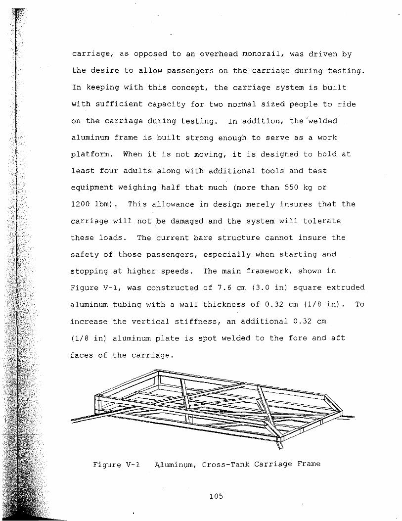
carriage, as opposed to an overhead monorail, was driven by
the desire to allow passengers on the carriage during testing.
In keeping with this concept, the carriage system is built
with sufficient capacity for two normal sized people to ride
on the carriage during testing. In addition, the/welded
aluminum frame is built strong enough to serve as a work
platform. When it is not moving, it is designed to hold at
least four adults along with additional tools and test
equipment weighing half that much (more than 550 kg or
1200 lbm). This allowance in design merely insures that the
carriage will not be damaged and the system will tolerate
these loads. The current bare structure cannot insure the
safety of those passengers, especially when starting and
stopping at higher speeds. The main framework, shown in
Figure V-1, was constructed of 7.6 cm (3.0 in) square extruded
aluminum tubing with a wall thickness of 0.32 cm (1/8 in). To
increase the vertical stiffness, an additional 0.32 cm
(1/8 in) aluminum plate is spot welded to the fore and aft
faces of the carriage.
Figure V-1 Aluminum, Cross-Tank Carriage Frame
105

In addition to weight bearing strength, the carriage needs
structural rigidity against forces applied to it by an object
in tow. Review of the predicted usage along with the various
fixturing schemes in the appendix identified the need for
certain hard points (stronger, more rigid places) on the
carriage. Tethered loads, such as the oil containment
barrier, were found to apply the highest forces along the
X-axis. These forces require frame stiffness only in the X-Y
plane so that its rectangular shape does not distort under
load. The frame is stiffened against such distortion by the
diagonal structural members shown in Figure V-2. Other loads,
especially large drag submerged loads, place more specialized
and demanding rigidity requirements on the carriage.
Fixturing of submerged loads is expected to be accomplished by
attaching the rod or strut holding the UUT to the frame by
some simple means. Simply bolting or clamping the uprights to
the frame's fore or aft face is probably the simplest
approach. This does, however, require a structure which is
very rigid to Z-axis and X-axis forces as well as large pitch
torques. Z-axis stiffness is insured by the face plate and
X-axis stiffness is accomplished by extending the diagonal
stiffening members (see Figure V-2) from the center of the
carriage's face plate where most such loads would be attached.
106

75
~--------------------~36,--------------------~
- 3' )< 3 1 ALUM] N UN
SQUARE rUB [NG
(ALL R[HA(N1NG FRAME)
'--H-------70,5>--------'
Figure V-2
L-__ O.l25' 1HICK ALUM1NUM PLATE, BOTH rACES
TOp View of the Carriage Frame
(Dimensions shown are in inches.)
The pitch torque stiffness is accomplished by extending those
same stiffening members from the top and bottom of the face
plates to converge at or near the wheel locations on the
opposite face as shown in Figure V-3. Finally, because of the
dominant siderail design, large yaw torques need to be spread
out on the dominant rail to minimize their resulting normal
forces on the rail. The large yaw torques result from large
X-axis loads at a distance of up to 1.8 meters (6.0 ft.) from
the rail. This is accomplished by extending the diagonal
107

bracing beyond the face plates of the carriage on the active
rail side. This can also be seen in Figure V-2. The
stiffening members in the final structure is a composite of
~-------------75~------------~
'-----'32.5' MAX~ Figure V-3
L 32S MAX~ Side View of the Carriage Frame
(Dimensions shown are in inches.)
the preceding stiffening schemes, as the off-angle view in the
earlier Figure V-1 depicts. These stiffeners are 1.5 cm (2.0
in) square, 0.32 cm (1/8 in) wall, aluminum tubing projected
through the rectangular frame structure. The frame is quite
complicated to view in three dimensions. To remedy the
problem, a model of the frame was created for conceptual
viewing and structural examination. When a vendor was
selected to build the frame, the model was delivered along
with the engineering drawings to simplify visual comprehension
of the structure. The model was reported as quite valuable to
the welders in this ,respect. Figures V-4 and v-s are
photographs of the model which may show the structure more
clearly than the previous figures.
108

109

The Primary Rail or Dominant Siderail
From a design standpoint, the dominant siderail held the
highest risk. The rail was not based on any proven design
because no similar system had been found. No similar systems
with square tubular rails or composite rails of any shape had
been observed. Steel, stainless steel, aluminum and
fiberglass materials were all considered for use as rails.
Steel was rejected for reasons of corrosion and potential
difficulty due to the forces required to correct any lack of
straightness in the rails. Stainless steel was judged too
expensive. Between aluminum and fiberglass, both were assumed
to be adequately corrosion resistant, and both were considered
soft enough to be subject to damage. The fiberglass, however,
was considered easier to repair if damage should occur and had
a coefficient of thermal expansion that was more closely
matched to that of the nominal coefficient for concrete. The
unproven, custom rail mount assemblies were designed and built
in house, thus there was also no history of their
effectiveness in calibrating and holding the rail in position.
Of the various modules that comprised the overall system, the
primary rail (including its mounting, assembly and
calibration) was the most expensive, most time consuming and
most dimensionallY critical. The main factor which mitigated
the design risk was the modularity of the overall system.
Should the fiberglass rail not measure up to expectations, it
110
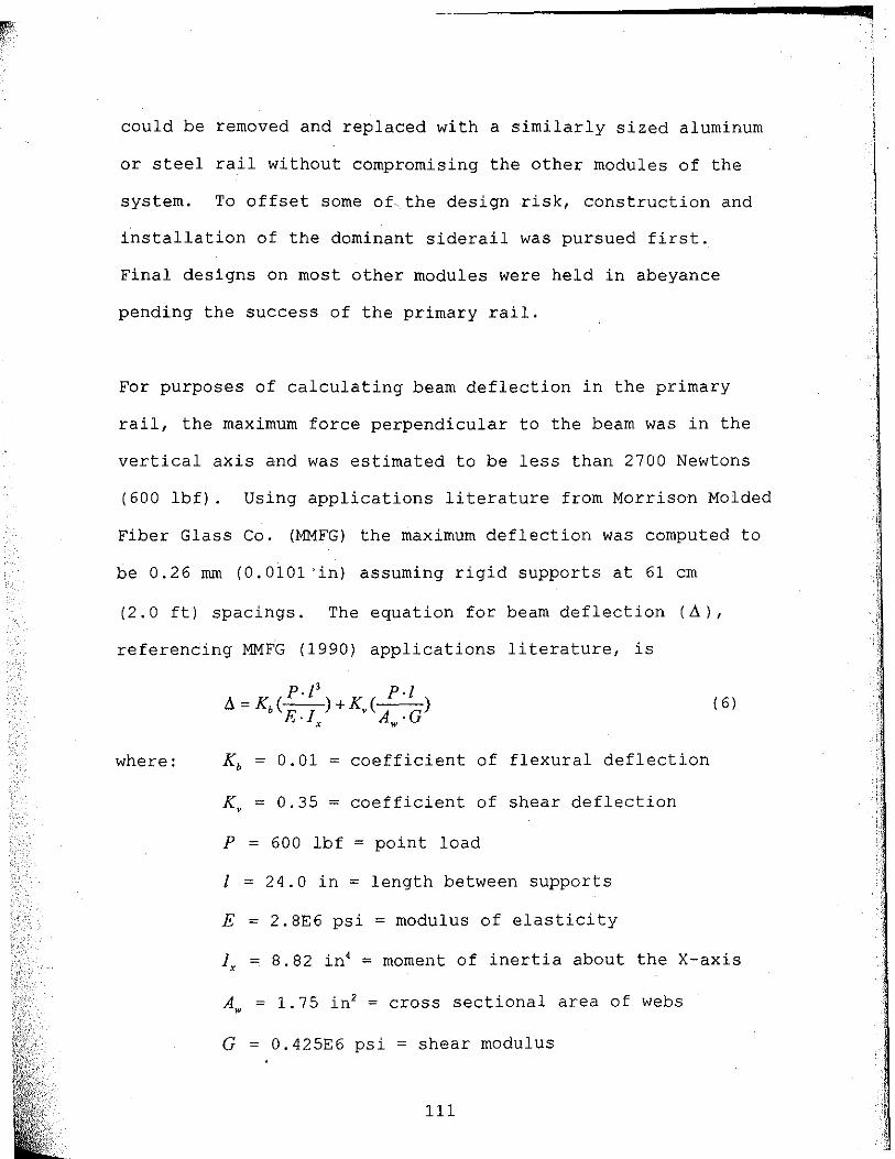
could be removed and replaced with a similarly sized aluminum
or steel rail without compromising the other modules of the
system. To offset some of,the design risk, construction and
i~stallation of the dominant siderail was pursued first.
Final designs on most other modules were held in abeyance
pending the success of the primary rail.
For purposes of calculating beam deflection in the primary
rail, the maximum force perpendicular to the beam was in the
vertical axis and was estimated to be less than 2700 Newtons
(600 lbf). Using applications literature from Morrison Molded
Fiber Glass Co. (MMFG) the maximum deflection was computed to
be 0.26 rom (0.0101 'in) assuming rigid supports at 61 cm
(2.0 ft) spacings. The equation for beam deflection (~),
referencing MMFG (1990) applications literature, is
~=K (P·I')+K ( P./) b E.I v A .G
x w
( 6)
where: Kb = 0.01 = coefficient of flexural deflection
Kv = 0.35 = coefficient of shear deflection
P = 600 1bf = point load
I = 24.0 in = length between supports
E = 2. 8E6 psi = modulus of elasticity
Ix = 8.82 in' = moment of inertia about the X-axis
A = 1.75 in2 = cross sectional area of webs w
G = O. 425E6 psi = shear modulus
111
q
t;.
" ,;

The EXTREN 525, 10.2 cm (4.0 in) square structural tubing was
purchased from Morrison Molded Fiber Glass Co. and shipped in
6.1 meter (20 ft) lengths. Because the tubing could not be
purchased in longer sections, the rail is subject to
discontinuities at its seams. All seams are supported by
extra wide seam plate supports instead of the usual narrow
rail mount assemblies. To make the critical center section
appear seamless, the ends of the rail are joined using a
biscuit joiner and fiberglass biscuits. The biscuits and the
carefully squared ends of the rails are glued together using
Sikadur 32 epoxy made by Sika Corp. The resulting joints are
surprisingly strong and, once sanded with fine sand paper,
they are nearly imperceptible to the touch.
The rail support assemblies are fastened to the top of the
concrete wall using stainless steel attachment studs. These
studs are set a minimum of 4 centimeters into the tank wall
and anchored into the concrete using Sikadur 32, two part
epoxy. Epoxy based anchors were used instead of compression
type anchors because of expressed concerns of weakening or
cracking the tank wall. To insure their integrity, a sample
anchor was tested. The sample anchor pulled out a conical
section of concrete at a pullout force of 13000 Newtons
(3000 lbf). All steps of the drilling, and placing of the 126
anchor studs were scrutinized using a surveyors transit and
112

spinning laser. The final placement accuracy was ~ 3 rom
(l/B in) in the tanks Y-axis and about the same vertically.
The dominant siderail mount assembly, with rail and cable
trough, is depicted in Figure V-6. The bottom plates were
grouted in place with A. H. Harris non-shrink construction
grout. The plates were simultaneously leveled with a simple
bubble level and calibrated in the Z-axis using the rotating
laser during grouting. The final accuracy of the bottom
plates was an error of less than ±.1. 6 rom (~1/16 in) over the
length of the rail. (These error measurements were verified
with a surveyors transit and are subject to its accuracy.)
The remaining error, within the ability of the transit to
discern, was reduced to +O.B rom (~1/32 in) by inserting shims.
-CABLE TROUGH
STOP PLATE-- I---PRIMARY RAIL
{fl1---ffi~~r=ll=r.==~~---TOP PLATE --------,---S HI M
~ ____ ~~~==~==~~~;;;;~=====BOTTOM PLATE ,.-- GROUT
III-----~,--SS ~ALL ANCHORS
---CONCRETE TANK ~ALL
Figure V-6 Primary Rail Mount Assembly
113

The fiberglass rail was attached to the top of the rail mount
assembly using blind threaded inserts, referred to as rivet
nuts. For added rail height the top and bottom plates of the
rail mount assembly were separated by a thick plastic shim.
The top assembly was fastened to the bottom plate by two cap
screws and Y-axis adjustment of the rail was accomplished by
sliding the top plate along slots through which the bolts
passed. Y-axis calibration was implemented to the limits of
what the transit could discern.
Secondary or Passive Rail
The overriding design constraint which drove the secondary
rail design was the self-imposed constraint of safety,
preferably passive safety, while still leaving the observation
side as accessible as possible. The top of the concrete tank
walls are 1.2 meters (4.0 ft.) above the floor with clearance
for easy access on all sides. The walls are the ideal height
to lay things on and to lean over while observing the tank.
The observation side of the tank (the side with windows) is
adjacent to the main walkway in a work area which is easily
accessible to the public. In this environment, an unguarded
rail on top of the wall has a high probability of causing some
sort of accident unless protected by fences or ,some other
means of keeping people away from the tank during testing.
The tow tanks observed at USNA and MIT served as excellent
examples of accessibility and safety. In both cases, because
114
of their overhead monorail type design, an observer could
actually sit on the side of the tank, with their legs dangling
in the water, during operation of the tank, with little risk
of an accident. By contrast, tow tanks with rails on top of
the walls were not safe to stand near during operation. A
story recounted by an operator of one such tank told of
rescuing an individual from the path of the oncoming carriage
because he was taking a picture and not paying attention to
the carriage. A personal observation at another facility was
that of watching an escort for a tour group move several
people from in front of an oncoming carriage in spite of the
warning buzzers and flashing .lights warning of its approach.
Just a few minutes earlier the escort had carefully explained
about the carriage and had pointed out the very clearly marked
stand clear zone.
Expensive acrylic shields (such as those around most hockey
rinks) were considered, but they would probably be at lea$t
partially removed for convenience during testing. Once
removed, shields might not get replaced immediately, if at
all. Shields or other access restricting devices would also
have compromised the versatility and accessibility of the
tank. •
A subtended secondary rail on the observation side of the tank
was found to be the optimum compromise. By placing the rail
115

such that the tops of the wheels on that rail fall a few
centimeters below the top of the tank, an observer may lean on
the tank wall and watch ongoing testing with minimal risk of
getting caught by the carriage or its wheels. By extending a
guard from the top of the tank over the wheels with a few
centimeters clearance, an observer may be so careless as to
grab the top of the tank with his fingers around the guard and
still suffer very little risk of injury. With the guard over
the wheels, -objects dangling over the tank wall are also less
likely to get entangled in the wheels.
The simplest implementation of the subtended rail would have
been to attach the rail directly to the concrete with anchor
bolts or some similar means. Concerns about compromising the
integrity of the tank wall by drilling it and implanting
anchors in the wall's face brought about the second overriding
design constraint of not drilling horizontally into the wall.
This constraint drove the complexity of the rail mounting
assembly. To facilitate placement of the passive rail inside
and below the top of the tank wall, a rail mounting assembly
was developed and constructed which anchored to the wall with
epoxied stainless steel anchor studs drilled into the top of
the tank wall. Stainless steel captive fasteners in the rail
mounting assembly allowed the rail to be attached in contact
with but not penetrating the inside wall of the tank.
116

Prior to attachment of the rail mount assembly, the top of the
tank wall was leveled. Before it was leveled the wall was
measured, using a surveyor's transit, and found to vary in
height by up to 3.2 cm (1.25 in.). A. H. Harris, non-shrink
construction grout, as used on the dominant rail mounts, and a
common floor leveling compound were both used successfully to
level the wall. The passive rail mounting assembly was
constructed of plywood for cost reasons. The plywood assembly
forms a cap over the top of the tank wall and the portion that
extends into the tank supports the subtended rail.
structural aluminum angle, 8.9 cm wide by 1.0 cm thick (3.5 in
wide by .38 in thick), was selected for the secondary rail.
Other rail shapes considered were round or rectangular
structural tubing. Round structural tubing was unnecessarily
difficult to mount and rectangular structural tubing was
rejected because it would have resulted in placing any
undercarriage wheels deeper in the tank than would be required
by a simple aluminum angle. Other materials were stainless
steel, which was too expensive and structural fiberglass which
proved to be too flexible because of its low modulus of
elasticity. A cross section of the final design for the rail
and rail mounting assembly is shown in Figure V-7. The
details of construction are described in the following
paragraphs.
117

3/4' X 3/4' HARDI.JODD STRIP-~
3/4' PL YI.JOOD
RAIL MOUNT PLATE
3.5" X 3.5" AL ANGLE
RAIL 3/8" THICK
SS BDLT~
5/8' PL YI.JODD FINISHED TOP
,-----3/4" PL YI.JOOD
SS CAPTIVE FASTENER
SPACER
,----ANCHOR STUDS
1/2" PL YI.JOOD
BOTTOM PLATE
-TANK I.JALL
Figure V-7 Secondary Rail Mount Assembly
After the wall was leveled, 7.6 cm long threaded stainless
steel rods were anchored into the wall at 1.2 meter spacings
using Sikadur 32 epoxy. The anchors extend 2.5 cm out of the
top of the wall. The 2.5 cm studs are long enough to allow
the first or bottom 1.3 cm layer of plywood to be bolted
down, but short enough that they do not extend above the next
1.9 cm layer of plywood, thereby allowing the top layer to be
attached over the studs. This scheme allows the top layer to
be clear of large bolts and bolt holes.
The first, 1.3 cm layer of exterior grade plywood was attached
to the inside plywood plate (see Figure V-7) using a 1.9 cm
square strip of mahogany, West System 105 epoxy and screws,
118

prior to either being attached to the tank wall. This method
of attachment provided more than adequate vertical shear
strength. The hardwood strip enhanced the strength of the
glued joint by greatly increasing the epoxied contact area on
both plywood plates and provided a place for the screws to be
inserted without compromising the laminations in the plywood.
Prior to attachment onto the tank wall, all layers of plywood
were painted. Because of its exposure to splash, the inside
plate was carefully covered with three coats of Palgard, two
part, epoxy coating from Pratt and Lambert, Inc. According to
their specificat~ons, this encapsulation method is tolerant to
complete submersion. Since it will see only occasional
splash, the inside plate should provide many years of service
without attention.
The bottom and second layer of plywood on the top of the wall
were painted with two coats of spar varnish. Before the
varnish had dried the second layer was attached to the bottom
plate with screws. By doing so, the two layers were glued
together over most of the length of the wall. Occasionally,
every six meters or so, the two layers were not glued together
to allow for easy removal if required.
119

The final layer of plywood and the outside trim board are non
structural. They were sanded, stained and painted with
several coats of polyurethane to produce a flat, smooth,
attractive finish which is sufficiently blemish free to be
used as a writing surface and is virtually impervious to water
damage. The top plate is secured to the bottom two layers
with brass screws and extends 4.5 cm past the mounting plate.
This extension of the top plate acts as a guard to keep the
fingers of negligent observers from dangerous contact with the
carriage wheels. As a useful finishing touch, a fiberglass
measuring tape was recessed and polyurethaned into the
finished top plate. The permanently attached metric measuring
tape, on the observation side of the tank is expected to be
routinely useful in setting up and documenting various
experiments in the tank.
The aluminum angle is held in place by stainless steel bolts
into captive fasteners in the mounting plate. The fasteners
are located every 0.61 meters and oversized holes drilled
through the aluminum angle allow for a small amount of
vertical calibration as the rail is being fastened to the
mounting plate. Tension in the bolts alone is not what holds
the rail in place, however. The largest force applied to the
rail assembly is vertical shear between the rail and the
mounting plate caused by the weight of the carriage and its
cargo. This shear is opposed by the friction between the rail
120

and the mounting plate, and the friction between these
surfaces has been greatly enhanced by a final coat of sand
filled epoxy paint in the contact area.
The Dominant Rail Bearing Beam
The dominant rail side of the carriage is attached to a
4.3 meter long beam, referred to in this study as the bearing
beam. The bearing beam rolls along the dominant rail on
wheels which are located on both ends of the beam. Figure V-8
depicts the bearing beam as it is attached to the cross-tank
carriage frame. Because of the nature of the dominant
r------3.7 METERS-------;
----'\lHEEL ASSEMBL Y
~--BEARING BEAM
4.0 M TERS
FRAME
---~IJHEEL ASSEMBLY
Figure V-8 Carriage Frame with Bearing Beam
siderail design, the yaw torques applied to the carriage can
be large. By design, these yaw torques are opposed only by Y-
121

axis forces applied to the wheels on the sides of the dominant
rail. To increase the carriages stability and rigidity with
respect to applied yaw torque and to minimize the Y-axis
forces applied to the rail, the wheels are located as far
apart as is reasonable. The 4.3 meter long bearing beam
permits the wheels to be separated by nearly 4 meters. With
the maximum towing force of 3100 Newtons applied to the
carriage along the centerline of the tank, 1.8 meters away,
the resulting yaw torque applied to the carriage is 5670
Newton-meters. with a wheel separation of 3.9 meters the
resulting force applied to the rail is only 1450 Newtons, less
than half the applied towing force. Figure V-9 is an end view
of the bearing beam showing wheels on all sides of the square /'
primary rail. Figure V-lO is a top view of the same wheel
assembly showing the inside and outside wheels in co-ntact with
the primary or main rail. Yaw torque and Y-axis forces are
opposed by the side mounted wheels while Z-axis loads and
pitch torque are opposed by the top wheels. The two bottom
wheels do not normally contact the rail unless the net forces
applied to the top wheels becomes negative. The side view of
the same wheel assembly in Figure V-II shows the top and
bottom wheels.
The inside wheels of the opposing wheels on the sides of the
rails are spring loaded. This was necessary to accommodate
122

TOP 'WHEEL--~
OUTSIDE 'WHEEL
RAIL MOUNT ASSY-----..
BEARING BEAM
PRIMARY RAIL
CABLE TROUGH
INSIDE 'WHEEL
UNDER RAIL 'WHEEL
.. TANK 'WALL
Figure V-9 End View of Bearing Beam, Rail & Wheels
123

OUTSIDE \O/HEEL
MAIN RAIL
TOP \.IHEEL
o
INSIDE \O/HEEL SPRING LOADED
UNDER RAIL \o/HEEL
CABLE TROUGH
Figure V-10 TOp View of Bearing Beam Wheel Assembly
TOP \O/HEEL
N RAIL
UNDER RAIL \O/HEEL
Figure V-11 Side View of Bearing Beam Wheel Assembly
124

the requirement of bi-directional towing capability. The
actual position of the carriage is keyed to the fixed wheels
on the top and outside of the bearing beam. Under load,
however, the forces on the trailing outside wheel can fall to
zero. When this happens the carriage position shifts by
rotating on the yaw axis until the inside trailing wheel comes
in contact with the rail. If the rail is exactly the same
thickness throughout its entire length and the wheels are
perfectly round, this yaw movement could be reduced to zero by
simply fixing both side wheels in contact with the rail
simultaneously. Unfortunately, if both wheels are fixed and
in contact with the rails, variations in the wheel and rail
dimensions cause deviations in the rolling friction along the
rail. Deviations in rolling friction result in unwanted
variations of carriage velo~ity.
Some of the tow tanks visited set the guide wheels with a very
small gap between them and the rails. When towed in one
direction, the carriage would lock its yaw rotation to the
forward outside wheel and the aft inside wheel. Traveling the
opposite direction, the opposite wheels keyed to the track.
This is essentially how the UNH carriage works, but its light
weight could allow the carriage to be rattled back and forth
between the sets of wheels. By spring loading both inside
wheels, the carriage travels with a constant load on its
inside wheels, in spite of dimensional variations in the rail
125

or wheels, until the spring force is exceeded. In addition to
the spring loading, the inside wheel assemblies· also have an
adjustable stop which limits its travel. When the spring
force is exceeded, the carriage shifts imperceptibly in the
yaw axis until the trailing inner .wheel reaches its travel
limit. The travel of the inner wheel can be fixed to less
than 2.0 millimeters resulting in a position variation in the
center of the carriage of less than 1.0 mm and a yaw angular
deviation of less than 0.0005 radians. Since the carriage is
fore/aft symmetrical,. it works equally well in both
directions.
In keeping with the overall modular nature of the design, the
carriage is attached to the bearing beam by nine bolts through
the frame into captive fasteners in the beam. The bearing
beam can be detached from the cross-tank structure and
operated with or without a replacement structure. All metals
used on the bearing beam, including the captive fasteners, are
either aluminum or stainless steel to minimize maintenance and
corrosion.
Wheels
12,7 cm (5 in) diameter, 5.1 cm (2.0 in) wide polyolefin
wheels with internal roller bearings were selected for the top
and side rollers in the bearing beam. The 5 x 2 inch
dimensions are relatively standard and this same size is
126

available in steel, stainless steel, hard and soft rubber,
neoprene, phenolic, nylon, polyurethane, and various
combinations of these materials, such as rubber on steel and
neoprene on phenolic. By selecting a standard size with so
many options, the wheels may be easily replaced with a more
suitable type if they are found to be less than ideal.
Polyolefin wheels are softer than fiberglass so they will not
be damaging to the fiberglass rail, yet they support up to
2900 Newtons (650 pounds) each. They are relatively
impervious to water and most chemicals, exhibit low rolling
resistance and, according to the sales literature, polyolefin
wheels "do not flat spot under load-. The hope is that if the
carriage is left standing for months, it will not develop flat
spots on its wheels causing it to roll irregularly along the
rail. The wheels on the passive secondary rail are also
polyolefin, but they are only 10.2 cm (4.0 in) in diameter.
Their smaller size allows for the subtended rail to be placed
closer to the top of the tank but their weight bearing
capability is reduced to 1800 Newtons (400 lbf). The small
3.8 cm (1.5 in) diameter neoprene wheels positioned underneath
the primary rail are expected to see only small loads, thus
their selection criteria was mostly for their ability to fit
in the space between the rail and the top of the tank.
127

Cable Attachment and Cable Trough
The bearing beam is propelled by a steel cable (wire rope)
which pulls it along the rail. Considering the length of the
cable and the loads applied to it, the cable could be quite
dangerous if it snaps. For sa~ety purposes the cable is
shielded over its entire length so that if it snaps it cannot
escape and injure bystanders. To facilitate enclosure while
at the same allowing the cable to be attached to the carriage,
a cable trough was fastened to the entire length of the
dominant rail. As shown in Figure V-12, the bearing beam is
attached to the cable through a slot in the top of the cable
trough by means of a cable attachment apparatus which will be
referred to as a cable grab. The cable is secured by
threading it through the cylinder on the cable grab and
subsequently attaching a stainless steel stop on the
galvanized steel cable using silver solder. The cable and
cable grab cylinder are then inserted into the trough and
bolted to the bearing beam as shown in Figure V-12. The
3.2 rom thick brace which holds the cylinder within the cable
trough passes through a 4.8 rom slot in the top of the cable
128

:::1--- TOP wHEEL r-f------1 {ATTACHMENT
LIi BOLTS
BEARING BEAM
e-- INSULATOR
". CABLE GRAB
[,=====::;!r~w-l+-ti=,-CABLE oQTM6QY RAIL _______ 1SJ1---1
'"' '1][ ""
V ;;;;::~II
ABLE TROUGH~ III II
INSIDE wHEEL ---j-+-
Figure V-12 End View of Bearing Beam with Cable Grab
trough. The slot in the trough is wide enough to allow for
the cable grab to pass through, but narrow enough that the
cable cannot escape without dissipating its energy. The sid~
view of the cable grab in Figure V-13 has the cable trough,
main rail and other clutter removed to more clearly show the
cable grab and the cable.
A final note about the cable grab is that it is electrically
insulated from the carriage. The fact that the carriage's
129
-

TOP \.IHEEL
CABLE GRAB
II III 1/
Figure V-13 Side View of Cable Grab & Cable
only electrical connection to earth ground is through the
cable was realized during the construction of the cable grab.
By placing nylon shoulder insulators on the attachment bolts
and a poly-vinyl-chloride (PVC) insulating spacer between the
cable grab attachment plate and the bearing beam, the carriage
was completely insulated from ground. The carriage can easily
be regrounded through the cable by electrically shorting
around or simply removing the nylon insulators. As an added
benefit, however, the carriage may alternatively be grounded
to the water in the vicinity of the UUT by means of its own
instrumentation, thereby creating the lowest possible ground
noise between the onboard instrumentation and the UUT in the
water. The carriage may also be left insulated from ground as
a safety precaution in some situations.
130

The Cable Path, Including Idle Sheaves and Tensioning
The cable is enclosed in a fiberglass cable trough as it
travels along the active rail. It returns along the bottom of
the tank wall through PVC plumbing pipe. At both ends of the
tank the cable travels through steel idle sheave assemblies
which reverse cable direction and allow for cable tensioning.
For cable inspection purposes, the faces of the sheave
assemblies are covered by a 3.2 rom thick clear polycarbonate
shield which is virtually shatterproof. The drive assembly is
located on the floor near the center of the tank.
Tensioning of the cable, as mentioned previously, is
accomplished in the idle sheave assemblies.. Once the cable
has been attached to the bearing beam, 16 centimeters of
coarse tensioning is available by moving the large idle
sheaves to their outer positions. An additional 5.2 cm of
finely adjustable tensioning is available by sliding the
smaller idle sheaves along their adjustment slots. Because of
the angle of the cable as it passes over .the smaller
adjustment sheave, the resulting cable tension is four to six
times the force required to slide it into position.
The Cable Drive Sheave
The cable drive sheave is actually a slightly modified V-belt
pulley. An unmodified pulley was found to be adequate for
most situations, however to achieve the maximum caDle tension
131

under less than ideal conditions, the normal 18 degree angle
of the vee groove needed to be decreased in a lathe. The less
than ideal conditions referred to are the result of wearing of
the cast iron sheave, creating a fine black iron powder which
lubricates the sheave much like graphite would. The
difference between a clean steelfcast iron interface with a
coefficient of friction of 0.4 (Handbook of Chemistry and
Physics, 1969) and a lubricited interface with a coefficient
of friction of around 0.1 accounts for slipping of the cable
at less than the required maximum tension.
The maximum theoretical tension applied to a cable around a
flat drum is governed by the equation
(7 )
where TT and T, are the tensions in the tight and slack sides
of the cable, f.J is the coefficient of friction and () is the
amount of contact around the drum in radians (Tribo10gy
Handbook, 1973). If the cable is placed in a vee grove the
equation becomes
p8 TT (-c-( )) _=e sma (8 ) T,
where a is the angle from normal to one side of the vee.
As stated previously, the cable is brought into contact with
the drive sheave for more than 75% of its circumference, so ()
132

is greater than 4.7 radians. TT Figure V-14 is a plot of Ts
versus a for a clean cast iron sheave (f.J = 0.4), a clean steel
sheave (f.J = 0.58) and either sheave with a moderate lubricant
such as graphi te ( f.J = 0.1) .
Cable Tension Ratio vs Vee Steepness
40
35 ~
'" ~ 30
0 25 :;:;
'" 0:: c:: 20 0 'iii c:: 15 II> l-II> :c 10 '" <..)
5
o
Vee Steepness (alpha) in Degrees
Figure V-14 TT Plot of vs a for Various Sheave Cohdi tions Ts
The drive force (Fe) applied to the carriage is the
difference between the cable tensions at both ends of the
carriage. ~ refers to the tight cable pulling the carriage
and Ts refers to the slack cable following the carriage. The
133
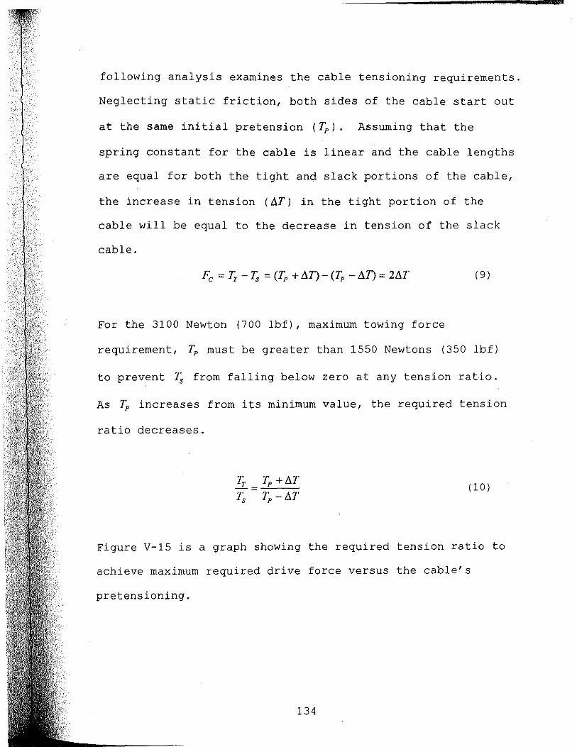
,
following analysis examines the cable tensioning requirements.
Neglecting static friction, both sides of the cable start out
at the same initial pretension (Tp ). Assuming that the
spring constant for the cable is linear and the cable lengths
are equal for both the tight and slack portions of the cable,
the increase in tension (aT) in the tight portion of the
cable will be equal to the decrease in tension of the slack
cable.
(9 )
For the 3100 Newton (700 lbf), maximum towing force
requirement, ~ must be greater than 1550 Newtons (350 lbf)
to prevent 1',; from falling below zero at any tension ratio.
As Tp increases from its minimum value, the required tension
ratio decreases.
'Fr Tp + aT -= Ts Tp - aT
(10)
Figure V-15 is a graph showing the required tension ratio to
achieve maximum required drive force versus the cable's
pretensioning.
134

35
~30 U)
~25 ~
,g20 I'll c::: 15 c: o 'ii510 c: {!!.5
o
Required Tension Ratio vs Cable Pretension to Achieve 3100 Newton Towing Force
1550 1650 1750 1850 1950 2050 2150 2250 2350 Cable Pretension in Newtons
Figure V-15 Required Tension Ratio for a Given Pretensioning
The preceding Figure V-14 shows that a cable tension ratio of
40/1 is easily achievable with an unmodified vee-belt pulley.
Figure V-15 shows that the pretensioning needs to be only 1650
Newtons to operate with that tension ratio. If the cable
becomes lubricated, however, the tension ratio falls below 5/1
for a standard pulley with a equal to 18 degrees. I f this
same partially lubricated pulley is modified to decrease a to
less than 12 degrees, only 1900 Newtons pretension is required
for the system to operate correctly.
Motor, Controller and Gearing
As discussed earlier, the ability to change gear ratios is
important for matching load requirements to the motor output
135

power and rotational speed. To implement this versatile
arrangement, an electric motor is connected to a gearbox via
pulleys and vee belts. The motor is a 10 hp, 208 volt,
1755 RPM, 3-phase AC motor, model A923A, made by U.S.
Electrical Motors. The gearbox is a Maxum, size 1, concentric
reducer, made by Dodge, with a fixed gear ratio of 3.406:1.
The cable drive sheave is attached to the output shaft of the
gearbox. Additional gear reductions of 4.8:1, 2:1 and 1:1 are
implemented though a selection of belts and pulleys. The
combination of pulleys and the gearbox result in net drive
reductions, from motor shaft to'cable drive sheave, of 16:1,
6.8:1 and 3.4:1. Using the maximum motor rotational speed of
1800 RPM and the 26 cm diameter of the cable drive sheave, the
maximum forward carriage speed is 1.5, 3.6 and 7.2 m/s (2.9,
7.0 and 14.0 knots) for the respective gear ratios. The
maximum towing force of 3100 Newtons is available only in the
lowest speed ratio.
The controller selected is a 230 VAC, inverter type, model
ID15H210-E, made by Baldor Electric Company. The adjustable
frequency command of the controller allows the carriage to be
driven either forward or reverse at any preprogrammed speed
between zero and the maximum forward carriage speed, in any of
the previously identified speed ranges.
136

CHAPTER VI
OPERATIONAL TESTING
Speeds and Acceleration
The completed towing carriage system was tested for maximum
speed and required acceleration distance, in all three speed
ranges. It was also tested for maximum towing force, at zero
forward velocity, in the lowest drive ratio. For purposes of
discussion, the ranges will be simply referred to as the high,
medium and low speed ranges. These ranges correspond to the
3.4:1, 6.8:1 and 16:1 drive ratio assemblages identified in
the previous chapter.
The forward velocity of the carriage was measured by timing
the passage of an attached flag through a photogate. The flag
was a piece of opaque gray PVC which was measured to be
35t±3~ inches long. This converts to 0.9048 meters + 0.1%.
The timers used were model ME-9215A photogate timers made by
Pasco, Inc. The six timers were individually identified by
their New Hampshire Technical Institute (NHTI) property tag
numbers 7267, 7268, 7270, 7271, 7274 and 7275.' Calibration of
the timers was checked by setting all of the timers side by
side over the shortest possible distance in the center section
137
. .

of the tank and comparing times. In three initial velocity
tests, all but one of the timers was found to agree with a
worst case error of less than 0.8%. A subsequent coarse
calibration check, by hand timing the carriage as it slowly
traversed a 10.0 meter span, also confirmed an error less than
1.0%. Readings from the unit NHTI# 7270 was consistently low
by about 2.6% of nominal, and was subsequently normalized to
reduce its error to less than 1.0%.
From data taken at a drive frequency of 60 HZi the measured
maximum carriage speed was 1.54, 3.70 and 7.12 m/s for the
respective low, medium and high speed ranges. The maximum
speeds were predicted, in the previous chapter, to be 1.5, 3.6
and 7.2 m/s respectively. Because of the crudeness with which
pulley ratios and drive sheave diameters could be measured,
correlation between predicted and actual speeds of this
accuracy is largely coincidental, however it does confirm the
general design predictions of maximum speed.
Acceleration was measured by placing the photogates at one
meter spacings from the carriage's start up position. the
carriage was considered fully accelerated when the times
recorded w~re within 10% of the times recorded on the farthest
two timers. Acceleration testing determined that the carriage
could reach 90% of its maximum speed in less than 1, 2 and
5 meters for the low, medium and high speed ranges
138

respectively. These measurements are not very precise and
little effort was expended in optimizing the programmed
acceleration time either. Actual minimum acceleration
distances are probably shorter, but in no case longer, than
those measured. Assuming that the carriage can decelerate in
a shorter distance than it accelerates, these measurements are
sufficient to confirm the nominal test length of the tank to
be at least 18 meters, even at high command velocities. The
nominal test length is the length of the tank during which the
carriage is capable of being at or close to the commanded
velocity.
Visual observations of the open loop carriage motion showed
some signs of damped oscillations at startup, especially in
the low speed range. The oscillations in velocity did not
appear to be a significant problem, though, and any
sensitivities that do exist should be minimized when the ideal
acceleration profile is incorporated or when a closed loop
control system can be implemented.
Towing Force Capability
The maximum towing force which could be applied to the
carriage from the drive train was limited by slippage of the
cable on the drive sheave. The towing system was tested for
maximum towing force at zero speed with the carriage
positioned near the center of the tank. The measurements of
139
&&

maximum towing force were taken by securing the carriage to
the stationary rail support blocks using ropes and linkages
connected to the carriage through a Model TC.S force
transducer made by T-Hydronics, Inc. The force block
amplifier and display was a Model 1601C, transducer indicator
made by Advanced Research and Eng., Inc. The instruments were
checked against an available scale and found to read about 3%
high. Measurements were attempted by commanding the drive
system to move slowly while the carriage was tied in place.
This resulted in transient forces which were much higher than
the actual slipping force. Measurements were subsequently
taken by manually turning the input of the drive transmission
and observing for signs of cable slippage on the drive sheave.
Initial measurements yielded maximum drive forces of about
1560 Newtons (350 lbf). Inspection of the drive sheave showed
significant wear and a powdery black residue (probably cast
iron worn from the sheave). The assumption was that the
residue lubricated the cable, causing the friction coefficient
to drop and the wear caused the vee groove angle (a) to
increase. The cable was cleaned and the sheave was replaced
by a sheave with a machined vee groove angle of approximately
12 degrees. The cable was then retensioned to approximately
4450 Newtons (1000 lbf) and the tests were rerun. The final
maximum towing force measurements were recorded to be 2255
140

Newtons (507 lbf), as per the instrumentation specified
previously.
The worst case predicted load of 3100 Newtons was calculated
at a forward velocity of 1.3 m/s (2.5 knots). Because towing
force for the test object increases with the square of the
velocity, the impact of the reduced towing force on that this
test load is subject to a reduction in the forward test
velocity of 15%.
Assessment of the predicted capability of the drive sheave
versus its actual performance indicate that factors outside
those accounted for in the belt friction equation were
affecting its performance. Quite possibly, nonlinear
stretching of the cable contributed to the error. Also, the
cable could have slipped for reasons unrelated to simple
friction, such as effects of high stress in the interface
between the cable and the cast iron sheave. Regardless,
improvements were seen from the initial tests with the
unmodified vee-belt pulley as a sheave, to the modified
steeper vee angle sheave. This, coupled with the closeness of
the current design to the final design goals, indicates that a
solution may be achieved by merely improving the drive sheave.
Possible changes in the drive sheave include using steel
instead of cast iron for a higher coefficient of friction and
less wear, a steeper vee groove, or a larger overall diameter
141

to increase the degrees of contact of the cable around the
sheave.
Analysis
The carriage system has been operated numerous times and has
already been used for two simple operational tests. One of
the operational tests was to verify the calibration of a
current meter and the other was to observe the low speed
performance of a small section of oil containment boom. The
following narrative is a collection of observations and
evaluations which.are valuable for establishing the success
and/or failure of the design, but are not normally measurable /
by objective means.
The carriage assembly, by itself, moves smoothly and easily on
the rails. The combined mass of the aluminum cross-tank
structure, the bearing beam and the wheels was measured during
construction to be 168 kg (370 Ibm). With the spring loaded
wheels set at zero preload, the carriage can easily be pushed
with one finger in spite of its weight. The cross-tank
structure has not yet been tested to its anticipated load of
four people with equipment while stationary and two people
during operation. It has on several occasions, however, had
two people climbing on it during test setup and a single
passenger during low speed testing. Judging from observations
142

during these events, no problems are expected in meeting the
anticipated design loads.
The cross-tank structure is designed to be a separate module,
quickly detachable from the bearing beam by removing nine
bolts. Detachment was required to correct a small amount of
distortion in the carriage structure. Detachment and
reattachment took less than an hour and required only one
person and the use of an overhead chain hoist.
Rigidity of the structure also appears adequate. No apparent
distortion of the frame was observed at any time during
testing, and most importantly, the face of the carr.iage seems
rigid enough to attach substantial pitch torque loads without
significant deflection. During testing, the ease with which
various test assemblies were attached to the face of the
carriage was quite satisfactory, although a center walkway on
the carriage would have been helpful. That center walkway was
anticipated in the design, but has not yet been installed.
The fiberglass primary rail system performs superbly. The
rail is impressively straight (~ 0.8 rom within the ability of
a transit to confirm). There is no discernible disturbance in
the smooth operation of the carriage as its wheels pass over
the seams in the calibrated center portion of the tank. The
cable grab through the narrow slot in the cable trough works
143

well in spite of the very tight tolerances. The acoustic
noise from the cable traveling throughout its entire path,
combined with the noise of the carriage wheels, is more than
anticipated, but adequately quiet for most applications.
The subtended secondary rail performed equally well. Its
safety aspects were well challenged during the current meter
calibration. As many as eight people, who were directly and
indirectly associated with the ongoing tests, were standing
near, laying things on and looking over the passive siderail
on the observation side of the tank during operation. Without
the subtended rail protecting the observers from their own
negligence, supervision of the testing would have been far
more difficult.
The finished wall cap was effective as a staging area for the
test assemblies, frequently used as a writing surface and
proved quite handy during testing. The embedded metric scale
proved invaluable in expediting testing and was effective for
use in positioning as well as in determining velocity in the
absence of dedicated instrumentation. In testing the
performance of the carriage itself, photogates were placed on
the finished surface according to position references from the
embedded tape. Velocity of the carriage was also checked by
timing the carriage between two points referenced from the
tape.
144

On the negative side, the cable drive system has more bounce
and at a lower frequency than is ideal. The unnecessarily
large mass of the vee-belt pulleys may be a prime contributor
to this problem. If so, reducing their mass may be desirable.
Also, a larger cable would help stiffen the system. Most
importantly, a properly implemented control system with the
proper ramp up and ramp down profiles would serve to minimize
this problem. Other minor disappointments included the
previously mentioned acoustic noise and the polyolefin wheels,
which are neither as quiet nor as free from flat spotting
under load as the sales literature indicated.
145

CHAPTER VII
DISCUSSION
Conclusions
The completed system works well and meets most of the
anticipated design requirements. The detailed breakdown is as
follows:
Carriage Propulsion Power -- With a 7.7 kW drive motor, the
system is capable of delivering more than the anticipated
4.0 kW propulsion power to the carriage in all drive ratios
tested. With a maximum drive force of 2255 Newtons, the drive
system cannot deliver 4.0 kW of drive power at speeds below
1.8 m/s.
Maximum No-Load Speed -- The top tested speed exceeds all
design requirements. The maximum measured velocity of the
carriage was 7.2 mis, nearly 40% greater than the desired
speed capability. The actual maximum speed is somewhat
higher. During testing, the motor was only driven to its
nominal frequency rating of 60 Hz. The motor is capable of
somewhat higher speeds for short periods of time, and has
already been driven at 80 Hz. With the available pulley
ratios, the system can easily exceed 7.7 .m/s (15 knots).
146

Without the cross-tank structure and with higher drive ratios
that speed could probably be doubled. Because of the
changeable drive ratio and the ability to detach most of the
carriage mass, the actual top speed of the carriage is limited
by its fail safe stops rather than by its drive system.
Bi-directional Towing Capability -- Towing capability of the
carriage was clearly demonstrated in both travel directions.
Measurements of velocity in both travel directions were equal
in both directions for a given velocity command, indicating
that the system towing capability is approximately
symmetrical.
Maximum Towing Force -- The maximum towing force measured was
2255 Newtons. The required maximum was 3100 Newtons. The
maximum towing force was not met. Problems with cable
slippage on the drive sheave resulted in the reduced drive
capability. Some possible improvements which could extend the
maximum towing force are discussed in the previous analysis
section.
Carriage Mass -- The final carriage mass was measured to be
168 kg (370 Ibm). The carriage was weighed dU'ring its final
integration with the system using the same Model TC.S force
transducer and Model 1601C transducer indicator used to
measure maximum towing force. The given measurement has been
147

corrected for the 3% transducer/indicator error. The cited
mass includes the cross-tank structure, the bearing beam and
all. wheels. This measurement does not include the mass of the
drive cable, center walkway or any instrumentation.
Maximum Pitch Torque -- No tests were run to measure the
actual pitch torque capability. Estimated pitch torque
capacity is well over the required capability, however.
The mass of the carriage is 168 kg, as cited previously. The
separation of wheels on the bearing beam is approximately
4.0 meters. This results in a pitch torque capability of
3,300 Newton-meters before the downward force on the rear
wheel drops to zero. In addition, an underrail wheel on the
bearing beam holds the rear wheel assembly to the rail
allowing for even higher pitch torques. The pitch torque
required for the submerged test load specified was only
2,250 Newton-meters.
Safety, Versatility and Ease of Use -- As discussed in the
preceding analysis, the system has already been put to several
uses. To whatever degree possible, the parameters of safety,
versatility and ease of use were demonstrated in those trials.
The final achievement of these parameters, however, is largely
dependent upon the incorporation of emergency stop shock
absorbers, a closed loop drive control, and other
148

instrumentation which did not fall within the scope of the
completion of this study.
With regard to work already completed, all reasonable design
concessions were made to insure the safety of system users as
well as casual onlookers. All reasonable design efforts were
extended to maximize versatility and ease of use. Ultimately,
however, these parameters can only be proven through years of
actual use.
Maintenance -- In keeping with the requirement for minimum
maintenance, wherever possible the system was constructed with
corrosion free components and constructed so as to minimize
maintenance. Sheaves and wheels were packed with synthetic
grease and are not expected to require further lubrication in
their operational lifetime. The Maxum gearbox is actually far
more rugged than is required for this application. It has
been filled with an appropriate lubricant and unless the
lubricant leaks out or is contaminated, no maintenance is
necessary. It is imperative, however, that all system
components be inspected prior to operation. Given below is a
suggested inspection/maintenance regimen to ensure that the
system is safe to operate. As usage of the system increases,
this regimen should be modified to reflect the knowledge
gained through experience.
149

Inspection/Maintenance Checklist
Rail System:
1. Inspect each rail for obstruction or damage
2. Wipe each rail clean.
3. Check for loose support bolts.
Drive system:
1. Inspect the pulleys for looseness or
misalignment, removing protective enclosure
as required.
2. Inspect belts for signs of fraying or slackness.
3. Replace enclosures if removed.
Cable System:
1. Inspect the cable for fraying. The cable may be
inspected by SLOWLY running the carriage from on
end of the tank to the other while viewing the
cable through the clear polycarbonate cover of
the idle sheave assemblies.
150

--------------------......... .. Cost -- The budgetary estimate for cost of construction was
$21,000. The actual cost of construction, excluding personal
time, was approximately $18,500. Work remaining, such as
emergency stops and the remaining electrical wiring may
account for some additional costs, but the overall budget was
met and the design decisions implemented were in keeping with
the intent of a cost effective towing carriage system.
151

Comparison to Similar Basins
Figures VII-1 through VII-6 compare the specifications of the
UNH tank with various other, similarly sized, basins. These
graphs show that the UNH tow tank is deeper, faster, has equal
or greater drive power and has a larger cross section than the
other tanks in the survey. In reviewing this data, however,
note that the large tanks at USNA and NSWC were excluded as
comparable to the UNH facility, because of their much greater
size. The large basins at either facility are superior in all
of these parameters, as would be expected.
45.0
40.0
cn 35 .O a:: ~30.0 w ::'25.0 z i:20.O f--~ 15.0 w ...J 10.0
5.0
0.0
Figure VII-1 Comparison of Tow Tank Lengths
152

4.0
3.5 en 3.0 0:: W I- 2.5 w ::;:
~ 2.0
J: 1.5 I-Cl
1.0 ~ 0.5
0.0 J: I- ~ 0 « « ~ z ~ :::> J:
C) Z :::> () en s: en :::> en
:::> z
Figure VII-2 Comparison of Tow Tank widths
3.5
3.0
(f)
ffi 2.5 I-w ::;: 2.0
~ 1.5 J: l-n.
1.0 w Cl
0.5
0.0 lNj MT NSV\C
Figure VII-3 Comparison of Tow Tank Depths
153

~ 12.0
« 10.0 W
I!:: «en ...JI!:: 8.0 «w 21-OW j::::;: 6.0 UW WI!:: en« 4.0 iZg 0 2.0 I!:: U
0.0 :z: l- ii: 15 c3 ~ U U 2 ~ ~ ~ :::J :::J :z: U en
~ en :::J en :::J 2 2 :::J
Figure VII-4 Comparison of Tow Tank Cross Sections
8.0 7.7
0 a 7.0 U W 6.0 !!? ~ 5.0 W I- 4.0 W ::;: 3.0 2 Ci 2.0 W ~ 1.0
en 0.0 :z: I- ir 15 « « U U 2 ~ :::J :z: (9 2 ~ ~ :::J
~ U en en :::J en :::J 2 2 :::J
Figure VII-5 Comparison of Tow Tank Maximum Speeds
154

8.0 en r: 7.0 « § 6.0
52 5.0
~ 4.0 0::
~ 3.0 o'~ a. 2.0
-~ 0:: 1.0
o 0.0 :r: z :J
Figure VII-6
(§ o en :J
« z en :J
Comparison of Tow Tank Drive Power
155

Future Work
The structural and drive portions of the tow tank carriage
were complete at the time of the writing of this thesis, but
much work still remains before the system is properly
functional and safe. The remaining work is beyond the
intended scope of this study. At present, the towing carriage
can be operated from the controller's programming keypad. The
keypad has forward, reverse and stop keys. The carriage can
be moved slowly into position using jog keys and can be
programmed to travel at various speeds by commanding the
inverter to drive the motor with an AC voltage of 2 to 60 Hz.
The speed at which the carriage travels, however, must be
externally measured. There is currently no position or
velocity sensing device associated with the carriage.
Furthermore, there is no closed loop control of the carriage
motion for stability or accuracy purposes. The following
paragraphs describe key function blocks and subsystems which
need to be incorporated to achieve the complete system
outlined in the design specifications.
Emergency stop Shock Absorbers -- To operate safely, some
means must exist to stop the carriage in the event that all
normal methods fail. The carriages at most of the facilities
visited had, at some point in their existence, been
inadvertently run past the normal limits of their rails,
156

hitting an obstruction and/or damaging the system. All
carriage systems had a limit switch of some sort to tell the
drive system to stop, but even well placed limit switches do
not guarantee that a collision with the end of the tank will
never happen.
For example, during testing with the highest speed range of
the UNH carriage, a trip switch was set near the center of the
tank. The trip switch did not command the motor to stop, but
simply turned the motor power off allowing the carriage to
coast to a stop. The carriage reached a speed of nearly
7.7m/sec (15 knots) before tripping the switch. From about
3 meters past the center of the tank, the carriage coasted the
entire remaining length tearing out two incidental
obstructions. The carriage continued past the obstructions to
the end of the rail and gently bounced off the idle sheave
assembly at the end of the rail. Fortunately, no damage
occurred to the system because all of the carriage's energy
had been dissipated by the time it gently bumped the end of
the rail. The information acquired from this incident,
however, dictates that trip switches would have to be placed
at or before the center of the tank to insure that the loaded
carriage would not impact the end of its rails. On the other
hand, trip switches placed at the center of the tank would
render the carriage useless in the critical center portion of
157
the tank. The alternative is to hit the stop switch instead
of the external trip switch.
The stop switch, on the Baldor controller, commands the motor
to an active stop by applying current to the fields of the
motor and dissipating the generated energy in the power lines
or in a resistor bank. Logically, then, stop switches could
be placed after the center of the tank and still stop the
loaded carriage in time. The stop switch is available in
certain modes of controller operation, and is remarkably
effective in bringing the carriage to a stop in about
6 meters, as long as everything operates as it is supposed to.
If the main circuit breaker trips, for instance, the motor
fields cannot be powered so the carriage would again be
allowed to coast. A more probable trip scenario would result
from the carriage hitting the stop switch and causing the
controller to trip itself off line because of the excessive
voltage feedback from the regenerating mode. The controller
is preprogrammed with a maximum safe line voltage. When the
controller detects that the limit has been exceeded, it
disconnects power from the motor leaving the system to coast
to a stop. During initial testing, this overvoltage
protection trip was observed in a benign situation.
To insure that the carriage comes to a safe stop in all
situations, a separate independent means of stopping the
158

carriage is required. The most reliable form of safely
stopping the carriage in all situations is some form of shock
absorber located at each end of the rails. Such absorbers c
were observed on several of the visited tow tanks. The shock
absorber could be implemented on the primary rail only and
could be built similar to those of a car or motorcycle, with a
spring to quickly absorb the carriage's energy and a valved
hydraulic piston to slowly dissipate the potential energy in
the spring. Efforts are currently underway to implement such
a system.
Closed Loop Control -- In keeping with the original design
objectives, the carriage controls should be simple to use and
usefully accurate. The intent of this design is to allow an
operator to command the carriage to travel at a particular
speed ( 3.0 meters per second or 5.0 knots) by simply typing
that speed and a few other bits of information into a
computer. Having done so, the carriage, on command, would
proceed in a stable manner, accurately, at that speed.
To complete this overall concept, a velocity feedback sensor,
a control computer and control software need to be added to
the system. The Baldor controller already allows for this and
several other modes of operation. The mode most likely to be
used permits control of the inverter's output frequency as a
function of an input voltage from another command device.
159

Implementation of the closed loop control would require
software which would detect the carriage's actual velocity,
and to increase or decrease the inverter's frequency to
minimize the difference between that and the command velocity.
Some control system analysis would be required to insure
stable acceleration and travel of the system. In addition,
various limit switches and detectors need to be fed back into
the command computer to insure that it can only be commanded
in a safe direction and that it cannot be commanded to travel,
unrestricted, to the ends of its rails.
On Carriage Instrumentation, Power and Communications Link
As outlined in the detailed specifications, the carriage
should be permanently instrumented with carriage position,
carriage velocity and water height (wave height) sensors. The
suggested accuracies of these devices are detailed in those.
specifications. Also, provisions should be made to easily
incorporate outputs from other instruments, such as strain
gauges, into the same data collection system.
The real time output of the position and velocity sensors,
along with any other control information, must then be
connected to an external control computer. All collected
data, along with at least one channel of video should also be
transmitted to an off carriage location in real time. For
best performance of the carriage, this should be implemented
160

without the use of a carriage umbilical. This could be
implemented through the use of a radio frequency or
laser/optical data communications link. Onboard electrical
power, required to operate the instrumentation, communications
link and any other electrical equipment added to the carriage.,
can be supplied from batteries and a 60 Hz inverter carried on
the carriage.
161

REFERENCES
Abkowitz, Martin A., 1969, Stability and Motion Control of Ocean Vehicles, The Massachusetts Institute of Technology Press, Cambridge, Massachusetts.
Barrott, Dave, 1994, Massachusetts Institute of Technology, Cambridge, Massachusetts, interview.
Bishop, R.E.D., & Clayton, B.R., 1982, Mechanics of Marine Vehicles, Gulf Publishing Co., Houston, Texas, 167-181 pp.
Bilgili, Ata, 1993, A Study of Bed-Load Sediment Transport in the Piscataqua River Navigation Channel, M.S. Thesis, University of New Hampshire, Durham, New Hampshire, 67-70 pp.
Coyne, Phillip Michael, 1995, Development of a Fast Current oil Containment Barrier, M.S. Thesis, University of New Hampshire, Durham, New Hampshire, 26 pp.
Compton, Roger, 1993, United States Naval Academy, Anapolis, Maryland, interview.
Doane, Christopher W., 1994, An Open-Channel Flume for the Study of Two-Dimensional Oil Containment Boom Models in Fast Current, M.S. Thesis, Univ. of New Hampshire, Durham, New Hampshire.
Handbook of Chemistry and Physics, 49th edition, 1964, editor Robert C. Weast, Chemical Rubber Company, Ohio.
Havelock, Sir Thomas, no date, The Collected Papers of Sir Thomas Havelock on Hydrodynamics, Office of Naval Research, Dept. of the Navy, ONR/ACR-103,609-610 pp.
Hinton, AI, & Peters, Don, 1994, Woods Hole Oceanographic Institute, Woods Hole, Massachusetts, interview.
Hoerner, Sighard F., 1965, Fluid Dynamic Drag, publish~d by author, Brick Town, New Jersey, 1-9, 3 7 pp.
Humphreys, D.E., 1976, Development of the Equations of Motion and Transfer Functions for Underwater Vehicles, NSCL 287-76.
162
"-,
-,; ,

Humphreys, D.E. and Smith, N.S., 1991, Hydrodynamics and Control of a Streamlined UUV Operating at 180-Degree Angle of Attack, ARAP Tech. Memo 91-11, ARAP Group, Titan Corp., Virginia.
Humphreys, D.E., 1993, ARAP Group, TITAN Corp, Bethesda, Maryland., interview.
Hutchinson, CDR Dwight, United.States Coast Guard Academy, New London, Connecticut, interview.
InterOcean Systems Inc., 1994, S4 Current Meter User's Manual, fourth edition, San Diego, California.
Lynch, Art, 1996, Offshore Model Basin, Escondido, California, interview.
Morrison Molded Fiber Glass Co., 1990, Design Manual for Fiberglass Structural Shapes, Bristol Verginia.
Phillips, Dick, 1995, Naval Undersea Warfare Center, Newport, Rhode Island, interview.
Principles of Naval Architecture, 1967, editor John P. Comstock, Society of Naval Architects and Marine Engineers, 292-338 pp.
Simoneau,· Larry, 1994, University of Rhode Island, Kingston, Rhode Island, interview.
Swift, M.R.~ Celikkol, B., & Coyne, P., 1995, "Development of a Rapid Current Containment Boom", Phase I report submitted to the U.S. Coast Guard, Volpe National Tran.sportation Systems Center, Cambridge, Massachusetts.
Swift, M.R., Coyne, P., Celikkol, B., & Doane, C.W., 1996, Oil Containment Performance of Submerged Plane Barriers", Journal of Marine Environment Engineering, Vol. 3, 47-61 pp.
Tribology Handbook, 1973, editor M. J. Neale, John Wiley & Sons, New York, A47 pp.
Warring, Thomas, 1996, Naval Surface Warfare Center, Carderock Div., Bethesda, Maryland, interview.
Washburn, Scott, 1996, A Wave Generator and Wave Absorber System for the University of New Hampshire Wave/Tow Tank, M.S. Thesis, University of New Hampshire, Durham, New Hampshire.
163

Appendix
Test Methods and Fixturing Requirements for Tow Tank Testing

Introduction
In the course of researching how to design and build the best
towing carriage for the UNH tow tank, numerous tests and test
fixtures were observed and discussed at the various facilities
visited. Although the choice of fixturing method and the
details of how various tests are fixtured are not necessarily
critical information in determining the best carriage design,
the information is quite valuable in clarifying how the system
might be used. This information might also prove valuable for
those readers who anticipate testing in this or some other tow
tank. Please note that, for the sake of brevity, throughout
this and other parts of the study the subject of testing may
be interchangeably referr~d to as an object or UUT (unit under
test) .
Measurement of Forward Drag of a Submerged Object
by Submerged Towing Tether
The simplest and probably the most common test of a submerged
object would be forward drag of that object at neutral
buoyancy. An effective method of conducting such a
measurement is to tow the object through the water by a nose
mounted tether. A simple fixture for implementing such a test
from an overhead carriage is shown in Figure A-I. Forward
drag force is determined by measuring the tension on the
tether at the velocity of the carriage.
165

Figure A-I
UUT
CARRIAGE
FORCE MEASUREMENT
BLOCK
HYDRODYNAMICALLY SHAPED STRUT -----~
TOW CAI3LE--------
FORWARD VElOCITY
Submerged Object on a Forward Tether
The simplicity of the setup makes this method of submerged
object drag testing valuable, but measurements are limited to
observation of flow and measurement of forward drag of
vehicles and objects which are neutrally buoyant and which
exhibit predominantly turbulent hydrodynamic flow patterns.
Tether tension cannot segregate buoyancy forces from drag
forces (ergo the neutral buoyancy requirement). Also, the
tether and strut preceding the UUT would interfere
significantly with flow around objects exhibiting laminar flow
characteristics. Examples of measurements achievable by this
method of fixturing include measurement of the force required
to tow a SCUBA diver through the water with various
outfitting, forward powering requirements of a typical
166

submersible vehicle, and the top forward speed of any of the
recent man-powered submarines. Measurement of laminar flow
hulls and measurement of forces other than those along the X
axis are examples of experiments which should not be fixtured
in this manner.
Measurement of Hydrodynamic Forces ana Submerged Object Using
a Stinger Support
The stinger support with force measurement blocks mounted
inside the object, as shown in Figure A-2, alleviates most of
the shortcomings associated with'the submerged towing tether.
This method of mounting the UUT to the towing carriage
theoretically fixes the position of the UUT in all degrees of
freedom with respect to the carriage and allows for
measurement of net forces applied to the UUT in all axes.
Placement of the force blocks inside the UUT separates
hydrodynamic forces on the support strut from those on the
UUT. The entire fixture can be tilted allowing the forces to
be measured with the UUT at a given angle of attack.
167

CARRIAGE ----
STINGER SUPPORT
FORCE MEASUREMENT BLOCKS
Figure A-2
FORWARD VELOCITY
Submerged Object on Stinger Mount
Stinger supports appear to be about the best method for
actually measuring laminar flow vehicles because forward
towing tethers and side struts disturb the total flow more
than stinger supports. Forward drag on such laminar flow
objects, however, tends to be so low that turbulent drag
associated with a cross sectional area as small as that of the
stinger can be significant in the overall measurement.
Discussions with Humphreys (1994), however, indicated that a
stinger large enough in diameter to rigidly support a
hydrodynamic test model, is also potentially large enough to
significantly affect the hydrodynamics of the vehicle.
168

.\
Measurement of Hydrodynamic Forces on a Submerged Object Using
Dual Side Struts
Hydrodynamic forces acting on a fast moving object can be
quite high in magnitude. As mentioned in the previous
paragraph, a stinger support, designed to provide rigid (non
resonant) support of a UUT, can interfere with some
measurements because it must be large in diameter. This is
especially true for a long UUT at a steep angle of attack
because of the long lever arm between the center of pressure
of the pitch and yaw hydrodynamic forces and the stinger
support. The double side strut fix turing shown in Figure A-3
has advantages for this type of testing. If the UUT is
rotated to a high pitch angle of attack, as shown in Figure
A-4, the large pitch forces are easily countered by
compression and tension of the two struts. This allows the
individual struts to be smaller than a single stinger support.
Note that the struts need to be small and hydrodynamically
shaped only in the boundary layer region around the UUT
because the force sensing blocks are again located inside the
UUT. Placing the force sensing blocks this way eliminates
strut drag from the measurement. Pitch rotation is arranged
such that the struts attach to the downstream or lee side of
the UUT to minimize the effects of the added turbulence caused
at the strut/UUT interface. Objects tested are often bodies
169

1 " l
1
I of revolution, thus at relatively high Reynolds nUmbers and
steep angles of attack they are so turbulent on the downstream
side that additional turbulence and drag caused by the support
struts is negligible.
Humphreys and Smith (1991) describe determination of forces
applied to an object at a steep angle of attack by computer
modeling with comparison to an actual model. Although the
study involved only computer models of such forces,
discussions with Humphreys (1993) included methods of
fixturing for such tests. At steep angles of attack,
Humphreys indicated that he preferred side strut fix turing
with the struts extending from the UUT on the highly turbulent
downstream s.ide of the model as shown in Figure A-4.
170

CARRIAGE
HYDRODYNAMICAU': .. _=::::::=:: SHAPED STRUTS ".
FORWARD VEtOCITY
Figure A-3 Submerged Object on Double Side Struts
HYDRODYNAMICALLY SHAPED STRUTS """,:::::::::::::::.._
DOWNSTREAM" -....:.---..... 'f TURBULENCE -
FORWARD VElOCITY
ANGLE OF ATTACK
Figure A-4 Submerged Object at a Steep Angle of Attack
171

l 'j
j
Measurement of Hydrodynamic Forces and Motions on a
Surface Vehicle or Object
Motions of a surface object differ from those of a submerged
object. Most obvious is the tendency of surface objects or
vehicles to exhibit violent pitch, roll and heave motions and
resonances. These motions come about because of an
underdamped equilibrium between buoyancy forces caused by Z-
axis (vertical) displacement and the acceleration of the
moving mass of the object. Resonant motions of a submerged
object are rarely of concern. One exception might be the
damped resonance in the roll axis of a cylindrical object,
such as a submarine. Even in this instance, however, the
motion is highly damped and more easily modeled than the
simple rocking of a surface boat.
To properly study the resonant motions of a surface object,
the object must be allowed complete freedom of movement in the
axes of concern. Any additional damping in the fix turing that
holds the surface object (i.e. bearing friction, etc.) can
significantly alter this resonant motion and thus reduce or
eliminate motions characteristic of that object. This is
contrary to submerged objects which are typically restrained
in all axes of motion during testing (see submerged object
fixturing). An ideal fixture for a surface object might be a
frictionless gimbal at the exact metacenter of the object
which is restrained in linear X-axis and Y-axis movement but
172

has complete frictionless freedom of heave, pitch, yaw and
roll movements. To date, no optimum method of achieving
frictionless freedom of motion in all stated axes has been
observed. Discussions within the preceding chapters of this
study evaluate those methods observed at MIT and USCGA which
have proven useful at their tow tank facilities (see Figures
111-3 and 111-5). Newer methods of motion measurement and
analysis include videotaping and three dimensional
computerized tracking of optical targets on the UUT. Video
taping or filming the UUT produces a frame by frame, time
sequenced record of the UUT's motions. The computerized
optical tracking method is implemented by placing optical
targets (small lights or light emitting diode~ are usually
used) on the UUT. Tracking of the targets in three
dimensional space is accomplished using a computer and three
orthogonally positioned video cameras. If the targets are
sufficiently brighter or otherwise distinguished from the UUT
and test area, the computer can establish and track their
position in all three axes.
2.3 Forces on a Stationary Bottom Object in a Flow
Figures A-5 and A-6 depict a method of fix turing which would
all'ow the tow tank to model stationary bottom objects in a
flow. An object fixtured in such a way simulates an object
fixed to a substrate in a surrounding flow of water, such as
an object on the bottom of a river. A major impact of the
173

fixturing shown in Figures A-S and A-6 is that it produces
large pitch moments on the overhead carriage. The drag of
large bottom mounted objects in high current flow, combined
with the drag of the traveling bottom platform, at some
distance from the carriage creates these large moments.
Arguably, anything that can be modeled on a bottom traveling
platform can also be modeled upside down on a surface
traveling platform, thus applying smaller forces to the
carriage. Proper modeling of an inverted bottom object on a
surface traveling platform would, however, require replacement
of net negative buoyancy with its equivalent positive buoyant
force throughout the model, thus complicating the process.
Furthermore, flow along a surface traveling platform would be
less restrained and slightly more prone to cavitation. These
complications tend to favor the consideration of an available
traveling bottom platform, but allowance for such tests places
rigorous design constraints on the overhead carriage to allow
for such forces.
174

b
SIMULATED
.CARRIAGE
HYDRODYNAMICAll Y,"",,=~ SHAPED STRUTS
BOTTOM OBJEC~T,--_-+ IN ·CURRENT-
FORWARD VElOCITY
Figure A-5 Simulated Bot.tom Object in Flow, Side View
CARRIAGE
HvDRODYNAMICAll Y Mt-------SHAPED STRUTS --------!.m
Figure A-6
SIMUlATED BOTTOM OBJECT~
IN· CURRENT 1 END VIEW (Forward Velocity
out of page)
Simulated Bottom Object in Flow, End View
175

Forces and Motions on Tethered Objects
The nature of investigations of tethered objects is expected
to be limited to measurement of drag forces, observation of
tether deployment and observation of stability and motion of
the tethered object. Fixturing requirements for tethered
objects is expected to fall into two main subcategorizes, a
submerged object towed on a cable or a bottom tethered .object
in a flow. The most easily fixtured simulation would be that
of a submerged object, such as a side-scan sonar, being towed
on a tether as shown in Figure A-7. Fixturing for a bottom
tethered object in a flow is slightly more complicated and
might be fixtured as in Figure A-8 & A-9, which depicts the
simulation of i:, surface buoy or instrument cluster anchored in
a current. Other examples of similar tethered objects include
towed linear acoustic arrays, multiple current meters on a
bottom moored cable or a moored fish-farm cage in ocean
currents.
176

CARRIAGE
FORCE MEASUREMENl
BLOCKS
TOW LAtllt-__ __
FORWARD VEtOCIlY
Figure A-7 Surface Tethered Object
177

TOW CABLE
SIMULATED TETHERED OBJECT
IN CURRENT
HYDRODYNAMICAll •..... :;:::~ SHAPED STRUTS -
FORWARD VEtOCITY
Figure A-8 Simulated Bottom Tethered Object, Side View
SUBMERGED TOW CABLE----
END VIEW (Forward Velocity
out of page)
SIMULATED TETHERED OBJECT
.... ,..--IN CURRENT .
HYDRODYNAMICALLY SHAPED STRUTS·
Figure A-9 Simulated Bottom Tethered Object in a Flow
178