a-track dcc - user guide - a-train systems · while every effort has been made to thoroughly test...
TRANSCRIPT

A-Track User Guide
User Guide
Version 4.3.2
© 2008-2014 JT Chamberlain
The copyright in this document is the property of JT Chamberlain, A-Train Systems February 2014

A-Track User Guide
Page 2 of 123 Version 4.3.2
CONTENTS
1 A-TRACK AND YOUR NCE DCC SYSTEM ...................................... 5 1.1 Principal Features of A-Track.............................................................. 5 1.2 Safeguarding Your DCC Decoder Configurations ................................. 7 1.3 Securing Power Pro Command Station & Handheld Cab Setups .......... 7 1.4 Additional Facilities ............................................................................ 8 1.5 Obtaining Your Copy of A-Track.......................................................... 9
2 GETTING STARTED .................................................................. 10 2.1 Starting the A-Track Program........................................................... 10 2.2 An Introductory Tutorial ................................................................... 18 2.3 Making a Quick Start......................................................................... 20
3 ITEMS AND ITEM LIST OPERATIONS....................................... 27 3.1 Accessing and Viewing Item Lists..................................................... 28 3.2 Item List Load and Save Options ...................................................... 33 3.3 Other File and Program Functions..................................................... 38 3.4 Editing - Undo, Redo, Find, and Selection ......................................... 39 3.5 Editing - Cut, Copy, and Paste........................................................... 41 3.6 Control - Allocation of Locomotive Items.......................................... 45 3.7 Control - Direct Operation of Locomotive Items................................ 47 3.8 Emergency Stop................................................................................ 50 3.9 Controlling Accessory Decoders........................................................ 52
4 ITEM OPERATIONS.................................................................. 56 4.1 Edit Configuration Variables Window................................................ 56 4.2 Speed and Speed Tables ................................................................... 61 4.3 Functions and Function Mapping....................................................... 67 4.4 Editing CV Values Directly................................................................. 67 4.5 Accessing Further CV Pages - Sound and Complex Functions ........... 69 4.6 Serial User Standard Interface (SUSI).............................................. 71 4.7 Transferring CV Values Between Items............................................. 72 4.8 Reading and Verifying CV Values ...................................................... 75 4.9 Programming CV Values ................................................................... 82 4.10 Defining and Assigning Locomotives to Consists .............................. 85 4.11 Accessories – Operation and Parameters.......................................... 86 4.12 Programming Accessory Decoders – Edit CVs Window...................... 94 4.13 Programming Accessory Decoders – Control Window....................... 99
5 USING MACROS TO CONTROL ACCESSORIES......................... 101
6 NCE POWER PRO COMMAND STATION & CAB OPERATIONS .. 102
7 REGISTRATION AND SUPPORT.............................................. 103 7.1 Registration and Activation ............................................................ 103 7.2 Key Points to Note about Registration / Activation ........................ 110 7.3 Obtaining Support and Reporting Problems.................................... 110 7.4 Suggestions or Proposals for Improvement.................................... 114

A-Track User Guide
Page 3 of 123 Version 4.3.2
8 A-TRACK MENUS - REFERENCE .............................................. 115 8.1 File.................................................................................................. 115 8.2 Edit ................................................................................................. 116 8.3 View ............................................................................................... 118 8.4 Item ............................................................................................... 121 8.5 Help ................................................................................................ 122 8.6 Pop-Up............................................................................................ 123
NCE, Power Cab, Smart Booster, Power Pro, PH Pro, ProCab, Cab04, Cab05, Cab06 and the NCE logo are trademarks of NCE Corporation, Copyright © 1994 - 2014

A-Track User Guide
Page 4 of 123 Version 4.3.2
DISCLAIMER
I hope you will like the A-Track for Windows program and enjoy using it as much as I have enjoyed creating the system, BUT . . .
While every effort has been made to thoroughly test and verify all functions incorporated into the A-Track for Windows application software when interfaced to the appropriate NCE hardware, please note that the software is supplied on an "as is" basis and without any warranty that it will perform faultlessly in your application. You use the A-Track for Windows application software and all associated hardware items at your own risk, and in accordance with the full terms of the end-user licence agreement which can be found in Chapter 13 of the A-Track Reference Manual.
The author and designer will not in any event be held liable for any improper operation of the A-Track for Windows program, or interference with any other equipment or software program, nor be held liable for any incidental or consequential damages of any sort arising out of its use.
Terry Chamberlain February, 2014
Acknowledgements
While all of the program code involved in the various parts of A-Track was written from scratch, using Visual Basic 6 (and some C), the author would like to acknowledge the inspiration provided by the work of the Java Model Railroad Interface (JMRI) group who showed what could be done when a PC is interfaced to commercial DCC equipment. Solving similar problems for yourself is made a lot easier by knowing that someone else has already found a solution – even if you do not understand exactly how they did it !
Thanks are especially due to Mark Gurries, of JMRI and formerly of the Silicon Valley Lines Model Railroad Club, who collected all of the publicly available NCE documentation together in his System Technical Manual, and continues to add to this data in his web pages. A-Track could not have advanced as far as it has done without this invaluable reference material.
The author would also like to thank the members of the Cochise and Western Model Railroad Club, and Charles Cole in particular, for their assistance in testing and using A-Track under real operating conditions - and for their patient support and help in ironing out the many bugs that cropped up during development.
NCE Corporation was not involved in the creation or development of A-Track.
A-Track User Guide
Page 5 of 123 Version 4.3.2
1 A-TRACK AND YOUR NCE DCC SYSTEM
This User Guide is intended to introduce you to the main features of A-Track, without going into too much detail. Please take the time to read at least this Introduction (Chapter 1) plus Chapter 2 (Getting Started) to help you get to grips with the program. Full details of all features can be found in the Reference Manual.
1.1 Principal Features of A-Track
A-Track for Windows (A-Track) is a powerful FREE extension to complement the facilities of your NCE Corporation Power Cab or Power Pro Digital Command Control system and to assist you in running your roster of locomotives on your model railroad. A-Track is a software application which runs, under Windows XP, Windows Vista, Windows 7, or Windows 8 on a standard Personal Computer (PC).
A-Track allows you to store full details of all of your locomotives, with all of their DCC configuration parameters, in a readily-accessible format on a personal computer – but without requiring you to be any kind of computer expert.
A-Track’s back-up copy of all of the data held within each DCC decoder fitted in the locomotives which make up your roster, safeguards all the hours of effort put in by you (or your Club’s DCC expert) in programming and configuration.
When linked to your NCE system, A-Track does not alter the way in which the NCE Command Station and Handheld Cabs operate, or are connected to the track and to each other, in any respect, so that you can continue to use them exactly as before – but with A-Track available to lend a powerful helping hand in the background.
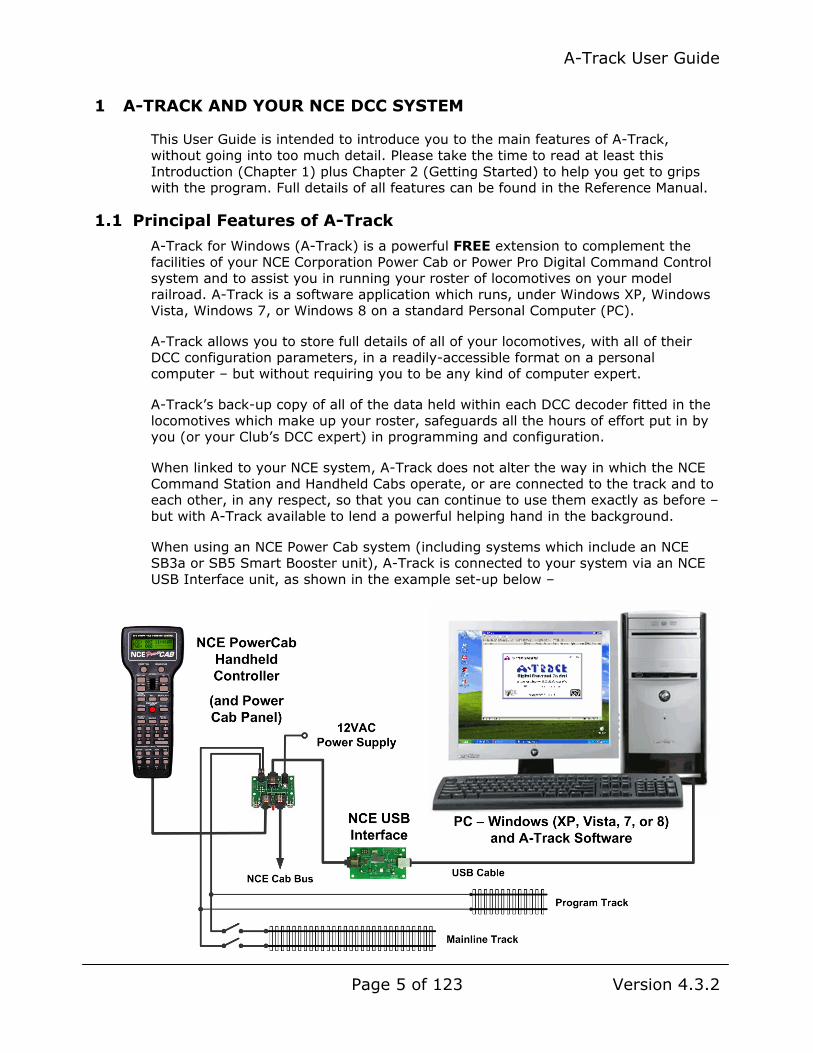
When using an NCE Power Cab system (including systems which include an NCE SB3a or SB5 Smart Booster unit), A-Track is connected to your system via an NCE USB Interface unit, as shown in the example set-up below –

A-Track User Guide
Page 6 of 123 Version 4.3.2
Alternatively, if you have an NCE Power Pro Command Station, you can connect A-Track to it via a standard Serial Port, if you have an older PC which is fitted with one, or via a USB Port and any readily-available USB-to-Serial (RS232) converter unit, as shown below –
When used with an NCE Power Pro system, as well as looking after the contents of your DCC decoders, A-Track will also let you monitor, set up, save, and restore the complete status and operational parameters of the NCE Command Station and all attached Handheld Controllers (Cabs) from your personal computer.
This gives you the ability to preserve and recall, at any time, the details of any particular operating session, including the assignment of specific locomotives to consists, and how these consists and other individual locomotives are allocated to each of your set of Cabs. Such a facility frees you from the task of having to set everything up from scratch at the start of a session, leaving you with more time to enjoy your model railroading.
Note, however, that neither the NCE Power Cab nor Smart Booster entry-level systems provide access to their internal status or parameters, so that A-Track is unable to offer Command Station or Handheld Cab back-up and restore facilities when linked to these systems.

A-Track User Guide
Page 7 of 123 Version 4.3.2
While A-Track will run quite happily as a background monitor of system operation when connected to your NCE Power Pro System, there is no requirement to run it continuously, leaving you free to start A-Track only at those times you wish to make use of its facilities. Keeping the PC connected, with A-Track inactive, will have no effect on the normal operation of your NCE equipment.
1.2 Safeguarding Your DCC Decoder Configurations
Using A-Track, you can read and save the status and parameters of each new locomotive decoder as delivered by the manufacturer. You will then be able to see the complete configuration details of the locomotive at a glance, on the PC screen, rather than only being able to check one parameter at a time by using a standard handheld Cab. A-Track can handle all types of decoders, including sound decoders, from all manufacturers who comply with National Model Railroad Association (NMRA) DCC standards. Currently, the system has been successfully tested with Digitrax, NCE, Lenz, SoundTraxx, QSI (Quantum), ESU (LokSound), Train Control Systems (TCS), Broadway Limited (Paragon 2), Model Rectifier, Bachmann, Hornby, and ZTC decoders.
A-Track gives you total control over decoder programming and locomotive tuning. You can make changes to the decoder parameters directly, without having to compute or type in complicated numerical values, then immediately try out the effects, and decide whether to keep the alterations or go back to the original values.
Being able to keep back-up copies of each decoder’s settings is especially valuable if you make an error in programming one or more parameters, and completely upset your careful tailoring of a locomotive’s performance and characteristics. A-Track will allow you to retrieve the previous decoder set-up and restore the locomotive to the state it was in before your inadvertent mistake.
Because A-Track lets you look at the decoder set-ups for several locomotives at the same time, and see the differences between them, it is relatively simple to tune the speed (and function) characteristics of these locomotives to run together in a consist. You can then run the locomotives individually, or together in the consist, on the track directly from the PC screen in order to check out the results, returning to the programming function if necessary to complete any fine tuning.
Whenever you purchase a new locomotive which is similar to one already in your roster, you can save a lot of programming time and effort by using A-Track to copy the decoder parameters from the configured locomotive to the new one – after making a back-up copy of the original settings in the new locomotive, of course (just in case !). Programming of the new locomotive is then reduced to giving it an appropriate description and a unique DCC address, together with any minor extra enhancements that you might want to make.
As well as handling locomotive decoders, A-Track also allows you to program and operate accessory (or stationary) decoders which are used primarily for the control of turnouts on your layout.
1.3 Securing Power Pro Command Station & Handheld Cab Setups
With NCE Power Pro systems, A-Track gives you full access to the Command Station, and hence the ability to display all of the key parameters stored in its internal memory on the PC screen. This allows you to perform Command Station

A-Track User Guide
Page 8 of 123 Version 4.3.2
and Handheld Cab setup directly from the computer, changing parameters to suit your immediate requirements, and to define and manipulate the composition of consists.
All parameters stored in the Command Station memory (System, Macros, Consists, and Cab Status) can be selectively saved (backed-up) to files on the PC’s hard disk, or on CD-R or a USB flash drive (memory stick), and then recalled at any future time to restore the Command Station and its attached Cabs to a state corresponding to a previously-recorded operating session.
The current size of hard disks, and the amount of RAM fitted, within a modern personal computer ensures that there is no practical limit to the number of different Command Station or Cab setups which can be saved to, or restored from, the computer’s permanent or removable storage.
1.4 Additional Facilities
Using A-Track you can look at, and compare, the major characteristics of any items of equipment on your roster to check, for example, that two locomotives have not been allocated the same DCC address – and thus avoid any future conflicts when attempting to operate them simultaneously on the same layout.
It is also possible to view complete groups of CVs together in a decoder, rather than only one CV at a time, to simplify complex set-up operations such as function re-mapping or the definition of speed tables.
A-Track allows all or part of the equipment roster to be saved to CD-R, to USB flash drive (memory stick), or to any other medium for safe-keeping, or for loading into another A-Track / NCE system elsewhere. Sets of CV values can be copied from one decoder to another, which can significantly reduce the time to program and set up a new locomotive added to your roster.
Programming of decoders can be performed directly from A-Track (through the NCE equipment) on either the Main Track (Operations Mode) or on a separate Program Track (Service Mode). Use of Service Mode on the Program Track allows the programmed values to be read back and verified as correct before releasing the locomotive under control on the Main Track.
Note that the NCE Power Pro has limited Program Track drive capabilities so that, particularly where sound decoders are fitted to your locomotives, it is strongly recommended that a programming track booster unit (such as the SoundTraxx PTB-100 or the DCC Specialities PowerPax) is inserted between the Command Station and the Program Track. Once fitted the unit can be left permanently connected for programming and verifying all types of decoders. A programming track booster unit is not generally required when using an NCE Power Cab which has a comparatively higher drive capability in Program mode.
Given the size of hard disks and the amount of RAM in a modern PC, A-Track can handle equipment roster lists stretching to hundreds (or even thousands) of equipment items. However, such large lists tend to be unwieldy to view and manipulate, so it is usually easier to compile shorter rosters – corresponding, for example, to an operating session – using the facilities available in A-Track.

A-Track User Guide
Page 9 of 123 Version 4.3.2
You can also use A-Track to define Macros which let you execute sets of turnout operations with a single action. Both NCE Power Pro and Power Cab systems support the definition and use of Macros, and A-Track gives you the capability to expand the rather limited Macro facilities of the Power Cab to equal those of Power Pro systems.
As well as its primary purpose of storing and manipulating the contents of DCC decoders, A-Track also allows you to control any selected locomotive on the Main Track directly from the PC, using the mouse and a ‘soft’ on-screen controller, by issuing DCC commands directly to the NCE Command Station.
Although this control function is really intended as a test facility, to check the results of programming a locomotive decoder, for example, you can call up and operate as many as eight ‘soft’ controllers on the screen simultaneously - if you think you possess the capability and dexterity to run eight locomotives simultaneously on the layout by yourself !
1.5 Obtaining Your Copy of A-Track
A-Track may be downloaded from the A-Train Systems website at –
http://www.a-train-systems.co.uk/getatrack.htm
- completely free of charge for your personal or club use. Support to resolve any problems which you may encounter in using A-Track is also available free through the website (see Section 7.3).
You can choose to download A-Track either as a simple executable Setup File together with the Reference Manual and/or User Guide and Installation Notes, or as a complete Installation Package (including Adobe Reader).
Click on the selected file to download, then select Save (not Run) to copy the file to a folder on your computer. In Windows XP the default location will be My Documents, or Downloads in Windows Vista, Windows 7, or Windows 8, although you can choose any other folder as a destination if you wish – but take note of where the file is saved so that you can locate it later for installation.
Once installed, you have the option of registering your copy of A-Track, also without any charge, as described in Section 9.1 of the Reference Manual. Registered users will have priority with regard to support and assistance in rectifying any problems which they come across.
If, after using A-Track, you think that it is of benefit to your model railroading activities, and would like to support future A-Track development and enhancements, then you are welcome to make a voluntary donation - but you will not be ‘nagged’ or pressured to do so.
Donations can be made safely and securely via PayPal, using any credit or debit card, even if you do not have a PayPal account of your own
Very Important : Please note that the term "completely free of charge" must not be confused with "free for you to exploit as you wish". A-Track is copyrighted software, and not a public domain product. You may not distribute or sell A-Track either alone or as part of any commercial item, as set out in detail in the terms of the A-Track licence in Chapter 13 of the A-Track Reference Manual.

A-Track User Guide
Page 10 of 123 Version 4.3.2
2 GETTING STARTED
To help you locate the information you need from this User Guide, if you use the electronic version (the .pdf file) in Adobe Reader, for example, you will find that all chapter and section headings are hyperlinked, so that you can jump to any part of the document from the Contents listing, shown by clicking on the bookmark icon, or via the View menu by going to Navigation Panels / Bookmarks.
In addition, you can also click on any reference in the text to another section of the User Guide, which will take you straight to that section. Click on the Back button to return to where you started. As an example, click on the reference to Section 7.3 (the number) to find out about obtaining help and support with any problems.
Note that, if you are planning to use a USB-to-Serial Converter or the NCE USB Interface unit to connect your PC to the NCE equipment, the associated driver software can be installed either before or after installation of the A-Track program, although both have to be correctly installed before the full functionality of A-Track will be available. However, in all cases, ensure that the driver software is installed before you connect the USB-to-Serial Converter or the NCE USB Interface unit to a USB port on your computer. Some guidance on the installation of the various varieties of driver software can be found in Chapter 11 of the Reference Manual.
Before starting installation of A-Track from the Full Installation Package, from a Distribution CD, or directly from the Setup File, ensure that no other applications are running on the PC, and that the active User has administrative rights (this is the normal status when the operating system is either Windows XP Home or Media Edition, in Windows Vista or Windows 7 Starter or Home Editions, and in Windows 8 Standard Edition, but you may need to log on as an Administrator when using Windows XP Professional Edition, Windows Vista and Windows 7 Business, Professional, or Ultimate Editions, or Windows 8 Professional or Enterprise Edition).
Just follow the on-screen prompts to complete the A-Track installation. If you encounter any problems, then full step-by-step instructions can be found in Chapter 3 of the Reference Manual.
Once the hardware and program are installed, A-Track can be run by any User - no aspect of A-Track operation requires administrator privileges.
2.1 Starting the A-Track Program
To launch A-Track double-click on the program icon ( ) on the Desktop. In Windows 8 a corresponding tile ( ) is placed on the Start Screen.
Throughout the User Guide, any reference to operation under Windows 8 applies equally to Windows 8.1.
In Windows versions other than Windows 8, you can also launch A-Track from the Start Menu by clicking on Start, then Programs (or All Programs, depending on your selected Start Menu format). Locate and move the mouse to the A-Track folder, and then click on the A-Track program as shown in the Windows XP screen-shot below, which also shows the A-Track Desktop icon.

A-Track User Guide
Page 11 of 123 Version 4.3.2
Note that, as well as an entry for the executable program, A-Track, the A-Track Start Menu folder also contains a link to the A-Track Help file. This file contains the full text of the A-Track Reference Manual and, as will be described later, can be accessed from anywhere within the A-Track program while it is running by using the normal Help menu, or by pressing the F1 key at any time.
In Windows 8 you can access the A-Track Help file from the Start Screen by a right-click on a blank area of the Start Screen, followed by a normal left-click on the ‘All apps’ option (or in Windows 8.1 click the All Apps button on the Start Screen), and then locating A-Track Help in the appropriate group of tiles –
Once you have started the program, by double-clicking the screen icon or tile ( ), or from the Start Menu, A-Track displays a start-up window in front of its main window, and then checks to see if an NCE Power Cab. Smart Booster, or Power Pro Command Station is connected to one of the PC’s Serial or USB ports (and powered-

A-Track User Guide
Page 12 of 123 Version 4.3.2
on). If no connection is detected, then you will see the window contents as displayed below –
The three indicators on the status bar (in the bottom righthand corner of the main A-Track window) are red to show that no NCE hardware unit is currently connected or operational.
Connecting an NCE Power Pro Command Station by plugging a suitable RS232 Serial cable or USB-to-Serial converter into the 9-pin Serial Port socket on the front panel of the Command Station, and the other end of the serial or USB cable into the appropriate PC port, will cause both the left- and rightmost indicators to turn green whenever the Command Station is switched on.
If a connection to the NCE Power Pro Command Station exists when A-Track is started, the program transfers the data representing the status of all Consists (sets of locomotives to be controlled as a single unit), as currently held in the Command Station, to the memory of the PC. Retrieval of the data block takes less than 10 seconds to complete, with progress displayed on the screen, as shown below. During the transfer period, you should not operate any of the NCE Handheld Controllers (Cabs) since there is a small risk that communications between A-Track and the Command Station can be disrupted.

A-Track User Guide
Page 13 of 123 Version 4.3.2
If you hover your mouse cursor over the status bar panels containing the NCE and COM indicators, pop-up labels will appear displaying, respectively, the Command Station Software Version, and which of your computer’s COM ports is currently being used by A-Track to connect to the Command Station, together with the bit (baud) rate at which the serial link is operating, as shown below –
You will also notice the display of a banner in the lower part of the start-up window inviting you to register (free) for full, priority support of A-Track. Registration is purely voluntary, and A-Track is fully functional in all respects after installation.
If you do choose to register your copy of A-Track, by following the simple steps described in Chapter 7, then, whenever you subsequently start A-Track, your name will be displayed in the start-up window instead of the registration invitation.
If an NCE Power Pro Command Station is not connected until after A-Track has completed its initialisation, loading of the Consist data block is postponed until the Command Station is plugged in, and powered on. Loading will then proceed as before (although it may take up to 10 seconds before the date transfer starts), with
A-Track User Guide
Page 14 of 123 Version 4.3.2
display of the progress bar in the centre of the A-Track window. Allow the data transfer to complete without interruption.
The third, middle indicator on the status bar, which is initially red, is used to show the progress of A-Track in acquiring the status of all NCE Handheld Cabs connected to the NCE Power Pro Command Station. After 15 seconds or so following retrieval of the Consist data, when A-Track has determined which Cabs have been connected to the Command Station, it will turn yellow, and eventually green when the full status of all connected Cabs has been retrieved. The time taken to complete this full scan is approximately 2 seconds per connected Cab. Note that the complete status for Cab Addresses 01 and 02 is always transferred to A-Track, whether or not Cabs with these addresses are actually connected, so that the minimum total scan period is about 20 seconds.
Thereafter, A-Track will check every 10 seconds, or so, that the NCE Command Station remains connected and powered on. If you are using a USB-to-Serial converter which is fitted with one or more LED indicators, then the indicators may flash to show the transfer of commands and responses.
You can update the displayed Cab allocation and status at any time by clicking the Refresh ( ) button on the A-Track toolbar or by clicking on View on the A-Track menu bar, followed by Refresh Item Allocation & Status. The current Cab allocation and status will be cleared from the Item List, with the middle indicator on the status bar returning to show red, then changing to yellow and eventually back to green when the full re-scan has been completed.
Connecting your computer (and A-Track) to an NCE Power Cab or Smart Booster, via an NCE USB Interface unit, will also result in both the left- and rightmost indicators turning green, assuming that the relevant NCE equipment is powered on.
However, when using an NCE Power Cab or Smart Booster as the Command Station, the third, middle indicator on the A-Track status bar will now be replaced by a small icon showing the type of connected unit reported by the NCE USB Interface, as shown below for an NCE Power Cab –

A-Track User Guide
Page 15 of 123 Version 4.3.2
Again, if you hover your mouse cursor over the status bar panels containing the NCE and COM indicators, pop-up labels will appear displaying, respectively, the NCE USB Interface Software Version, and which of your computer’s COM ports is currently being used by A-Track to connect to the Interface, together with the bit (baud) rate at which the serial link is operating, as shown below –
Note that the NCE USB Interface does not actually identify the type of NCE equipment to which it is connected, but simply reports the current setting of its four configuration jumper links. See the NCE USB Interface documentation for full details.
To ensure that A-Track will generate the correct set of commands when communicating with the NCE equipment, you should take care to set the NCE USB Interface configuration links so that their positions correspond to whatever type of NCE Command Station is connected to the other side of the NCE USB Interface. The position of the configuration links should only be changed when the NCE USB Interface unit is not powered, ie. disconnected from the Cab Bus (unplug the lead from the 6-pin RJ12 connector)
A-Track User Guide
Page 16 of 123 Version 4.3.2
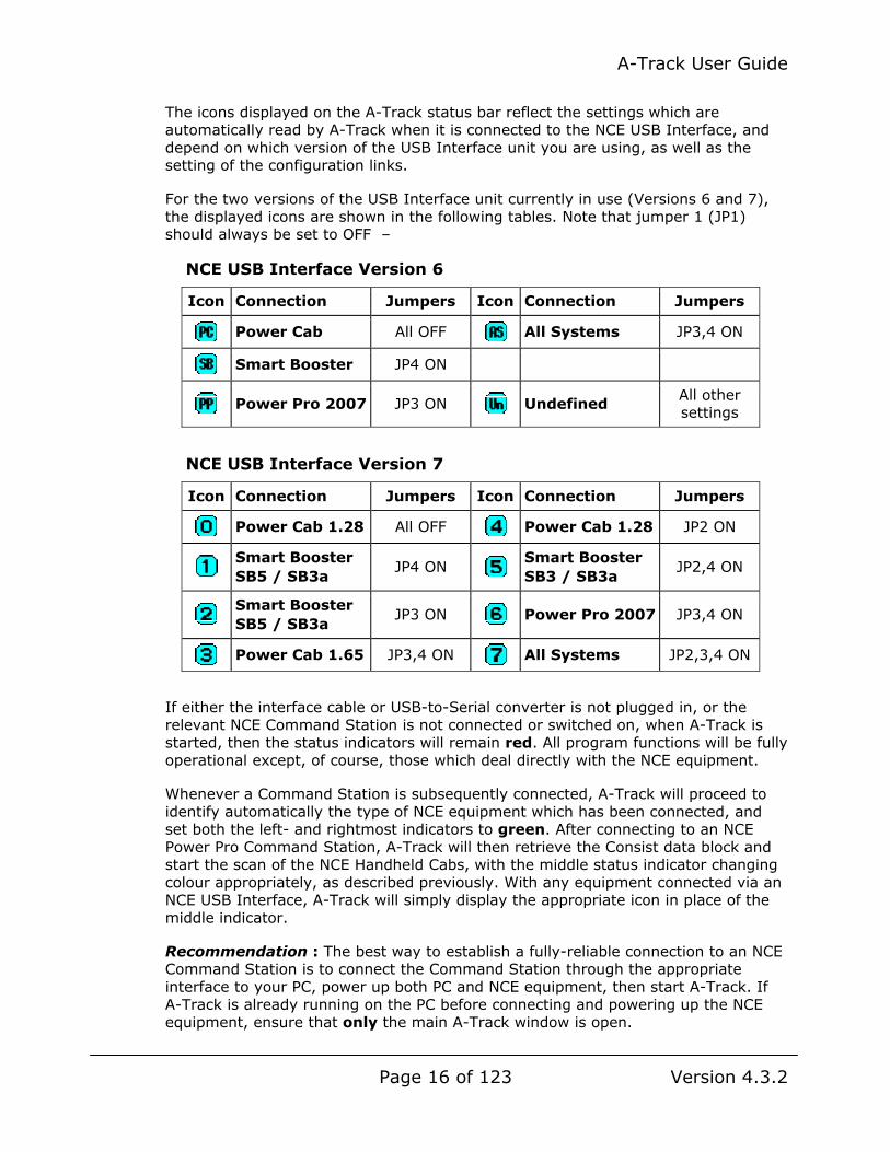
The icons displayed on the A-Track status bar reflect the settings which are automatically read by A-Track when it is connected to the NCE USB Interface, and depend on which version of the USB Interface unit you are using, as well as the setting of the configuration links.
For the two versions of the USB Interface unit currently in use (Versions 6 and 7), the displayed icons are shown in the following tables. Note that jumper 1 (JP1) should always be set to OFF –
NCE USB Interface Version 6
Icon Connection Jumpers Icon Connection Jumpers
Power Cab All OFF All Systems JP3,4 ON
Smart Booster JP4 ON
Power Pro 2007 JP3 ON Undefined All other settings
NCE USB Interface Version 7
Icon Connection Jumpers Icon Connection Jumpers
Power Cab 1.28 All OFF Power Cab 1.28 JP2 ON
Smart Booster SB5 / SB3a
JP4 ON Smart Booster SB3 / SB3a
JP2,4 ON
Smart Booster SB5 / SB3a
JP3 ON Power Pro 2007 JP3,4 ON
Power Cab 1.65 JP3,4 ON All Systems JP2,3,4 ON
If either the interface cable or USB-to-Serial converter is not plugged in, or the relevant NCE Command Station is not connected or switched on, when A-Track is started, then the status indicators will remain red. All program functions will be fully operational except, of course, those which deal directly with the NCE equipment.
Whenever a Command Station is subsequently connected, A-Track will proceed to identify automatically the type of NCE equipment which has been connected, and set both the left- and rightmost indicators to green. After connecting to an NCE Power Pro Command Station, A-Track will then retrieve the Consist data block and start the scan of the NCE Handheld Cabs, with the middle status indicator changing colour appropriately, as described previously. With any equipment connected via an NCE USB Interface, A-Track will simply display the appropriate icon in place of the middle indicator.
Recommendation : The best way to establish a fully-reliable connection to an NCE Command Station is to connect the Command Station through the appropriate interface to your PC, power up both PC and NCE equipment, then start A-Track. If A-Track is already running on the PC before connecting and powering up the NCE equipment, ensure that only the main A-Track window is open.

A-Track User Guide
Page 17 of 123 Version 4.3.2
Note that, once a connection has been established, if the NCE Command Station is disconnected or switched off, the leftmost indicator will change to yellow, returning to green when the unit is again operational. Note that A-Track may take up to 10 seconds to react to any change in the state of the Command Station.
If, on the other hand, the interface cable is disconnected from the PC, then both of the left- and rightmost indicators will change to yellow within 2 seconds, returning to green when the connection is re-established (and the Command Station is operational).
However, it is advisable that the Command Station is not deliberately disconnected from the PC Serial or USB port while the A-Track program is running, to avoid any possible data corruption, although such disconnection will not result in any physical damage to the unit.
If the switch-off, disconnection, or other communication error does occur at a critical time when data is being transferred to or from the Command Station, then the hardware or software may be left in a state from which an orderly recovery is not possible.
This is very likely to occur if the disruption occurs during the A-Track initialisation period, or if the equipment is re-connected very quickly after any disconnection. In such cases, first disconnect the serial or USB cable, then close down A-Track (see Section 3.3), and switch off the NCE Command Station. Allow around 20 seconds for the Command Station to power down fully, then switch it back on, reconnect the cable to the PC, and start the A-Track program again.
With an NCE Power Pro Command Station, the middle status indicator will revert to red after any disconnection, then subsequently show yellow and green after reconnection and completion of a full Handheld Cab status scan.

A-Track User Guide
Page 18 of 123 Version 4.3.2
2.2 An Introductory Tutorial
Once A-Track has completed its initialisation, the start-up window disappears and will be replaced by a Tutorial window which you can use to get a feel for the basic facilities provided by the A-Track program, including how to access the key menus and functions, and which will then guide you through the first steps in using A-Track with your own roster of locomotives.
The opening page of the Tutorial is shown below, with its straightforward controls. Having read the first page, click on the Next button to display the next page. Thereafter, you can return to a previous page by clicking the Back button, which will then be enabled. For your information, the number of the current page is displayed in the bottom righthand corner of the Tutorial window.
If you want further information about the topic described on any Tutorial page then a click on the More Info button will open another window showing the appropriate section from the full A-Track Help Topics (the contents of the Reference Manual).
You can stop viewing the Tutorial, and remove it from the screen, at any time by clicking on the Close Window button.
Although the Tutorial window is always displayed in front of the main A-Track window, you should drag it to one side, to leave the Tutorial window on the screen where you can see most of the main A-Track window as well the contents of the Tutorial (move the mouse pointer to the window title bar, where the text ‘Start-Up

A-Track User Guide
Page 19 of 123 Version 4.3.2
Tutorial’ is shown, hold down the left mouse button, and move the mouse to drag the window to where you want it to be, then release the mouse button).
As you step through the Tutorial, various A-Track functions and features will be demonstrated, with additional windows being opened as necessary. It is important to note that all of the main A-Track controls, and those in all of the demonstration windows, are fully operational when the Tutorial is running, especially if an NCE Command Station is connected and powered-on (as indicated here). Hence, you are free to explore further, at any time, any A-Track feature which is of interest to you – which is by far the best way to get to grips with A-Track. You cannot cause any damage to the program or its files by doing so.
However, note that, after branching off on your own from the Tutorial, and changing the state of the loaded A-Track data, it may not be possible for the Tutorial to continue on its intended course, when you click the Next or Back button. A message to this effect will be displayed, inviting you to click Close Window, after which you can, if you wish, restart the Tutorial by clicking on Help on the A-Track menu bar, followed by Start-Up Tutorial (See the menu details in Section 8.5).
The Start-Up Tutorial window will appear each time you start A-Track unless you click on the ‘Do not display at start-up’ checkbox in the bottom-left corner of the window. At any future time after you have done this, the Tutorial window can be displayed once more from the Help menu by selecting Start-Up Tutorial.
If you want to print out any page shown in the Tutorial window for reference, you can highlight the text by using the normal Windows procedure with the left mouse button, copy the highlighted text (hold down either Ctrl (Control) key, then press the C key), and paste it into any word processor.
A more comprehensive set of Help pages (the full text of the Reference Manual) can be viewed by clicking on Help / Help Topics on the A-Track menu bar, or on the
icon on the A-Track toolbar, or by pressing the F1 key on the keyboard at any time. Using the F1 key will open the Help Topic most appropriate to the current A-Track activity in progress.
As noted in Section 2.1, you can also access the Help pages directly (without running the A-Track program) from the Windows Start Menu, by clicking on Program Files, selecting A-Track, then clicking again on A-Track Help.
From the Windows 8 Start Screen, the link to the A-Track Help file is revealed by right-clicking on a blank area of the screen, then on the ‘All apps’ option, and then locating the Help entry in the A-Track group of tiles.

A-Track User Guide
Page 20 of 123 Version 4.3.2
2.3 Making a Quick Start
If you do not wish to work your way through the complete Tutorial, the final part, which takes you through your first practical steps in using A-Track, where you can collect details from selected locomotives in your roster, is detailed in this Section of the User Guide for your convenience.
It is assumed that you have gleaned enough from the Tutorial to understand that the details of each of your locomotives (or other pieces of equipment) in your roster will be held by A-Track as an Item, with a group of Items forming an Item List. Full details of Item Lists, and of Item List operation, are covered later in Chapter 3.
Ensure that your computer is connected to, and communicating with, an operational NCE Command Station – either a Power Cab or Power Pro system – with the status indicators in the bottom righthand corner of the A-Track window showing green, as described in Section 2.1 above.
Next, click on File on the Menu Bar, and then New, as shown below –
- which will create your first Item List, containing a single blank Item, that you can then use to collect full details of the first locomotive in your roster –
At this point you can, if you wish, click on Edit, and then on Insert Blank Item, to add further blank Items to match the number of locomotives you have. Alternatively, you can repeatedly click on the icon on the Toolbar to perform the same operation – or you can leave this step until later –

A-Track User Guide
Page 21 of 123 Version 4.3.2
Now, double-click on one of the blank Items in the Item List – which will open an Edit Configuration Variables window. You can refer, in due course, to Chapter 4 (Item Operations) in this User Guide for more information on the features and functions to be found in the Edit CVs window.
For the moment, press the F1 key on the PC keyboard –
A-Track User Guide
Page 22 of 123 Version 4.3.2
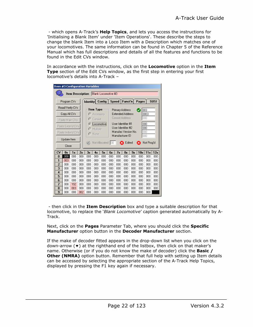
- which opens A-Track’s Help Topics, and lets you access the instructions for 'Initialising a Blank Item' under 'Item Operations'. These describe the steps to change the blank Item into a Loco Item with a Description which matches one of your locomotives. The same information can be found in Chapter 5 of the Reference Manual which has full descriptions and details of all the features and functions to be found in the Edit CVs window.
In accordance with the instructions, click on the Locomotive option in the Item Type section of the Edit CVs window, as the first step in entering your first locomotive’s details into A-Track –
- then click in the Item Description box and type a suitable description for that locomotive, to replace the ‘Blank Locomotive’ caption generated automatically by A-Track.
Next, click on the Pages Parameter Tab, where you should click the Specific Manufacturer option button in the Decoder Manufacturer section.
If the make of decoder fitted appears in the drop-down list when you click on the down-arrow ( ) at the righthand end of the listbox, then click on that maker’s name. Otherwise (or if you do not know the make of decoder) click the Basic / Other (NMRA) option button. Remember that full help with setting up Item details can be accessed by selecting the appropriate section of the A-Track Help Topics, displayed by pressing the F1 key again if necessary.

A-Track User Guide
Page 23 of 123 Version 4.3.2
Before adding any more details to your newly-created Loco Item, the safe way forward is to click the Update Item button to save the basic Item back to the Item List.
With the first initialised Item shown in the Item List, you can repeat the same steps with each of any other blank Items you added to the new Item List, by double- clicking on them to open their own Edit CVs window, and finally saving the updated Items back to the Item List.
At this point, before proceeding to the next stage of collecting each Item’s Configuration Variable values from the actual locomotives, it is a good idea to safeguard your initialised Item List, by saving it to a folder on your PC. To do this, click on File on the Menu Bar, followed by Save As, on the drop-down menu.
When the A-Track - Save Item List window appears, a suggested filename with today’s date is displayed (New-ItemList-11-May-13.itl in this example) – you are free to change it to whatever other format you prefer.
If you ran the Tutorial to the stage of loading the demonstration Item List, then the destination folder offered will be Documents / A-Track Item Lists (otherwise Documents or My Documents), but you can select any other folder if you wish. Click the down-arrow ( ) at the end of the Save In: listbox to view folders, as shown below for Windows XP, or select them from the folder list in the lefthand pane in Windows Vista, Windows 7, or Windows 8, or choose to create a new folder, into which to store the Item List (see Section 3.2) –

A-Track User Guide
Page 24 of 123 Version 4.3.2
Once you are satisfied with the choice of destination folder, and the filename, click Save to save your new Item List file to the selected folder (or Cancel to abandon the operation).
The next step is to again double-click on your just-initialised Item in the Item List to re-open its Edit CVs window.
Now, place your first locomotive on your programming track (or, if you are using a Power Cab and do not have a separate, switched programming track as shown in the connection diagram in Section 1.1), ensure that it is the ONLY locomotive on the main track). Note that, if your locomotive has a sound decoder, and you are using an NCE Power Pro system, then you will generally need to connect a programming booster unit (such as the SoundTraxx PTB-100 or DCC Specialities PowerPax) between the Power Pro and the programming track – a booster is not usually required with an NCE Power Cab system.
Click the Read/Verify CVs button in the Edit CVs window to display the Read/ Verify Configuration Variables panel where, for a first attempt at reading your locomotive decoder’s CV values, you should set the CV Range and Scope options to Current View and All CVs, and the Mode to Paged. While Direct Mode will read CV values more quickly, it is not always supported. Paged Mode is generally guaranteed to work but, the higher the CV’s programmed value, the longer it takes to determine the actual value of the CV from the decoder –

A-Track User Guide
Page 25 of 123 Version 4.3.2
When you have set the options, click Confirm to start the Read/Verify operation.
During the Read/Verify operation, the CV currently being accessed will be highlighted in red in the grid in the lower half of the Edit CVs window. Once the CV value held in the decoder has been determined, it will be displayed in the grid and highlighted in light green if the value read is the same as that held in the Item, or highlighted in pink if it differs from the Item’s stored value.
Wait patiently while the first 128 CV values are read from the decoder and displayed in the grid. If required, the whole operation can be stopped at any time by clicking the Cancel button, although you will have to wait for the current CV Paged Read operation to complete (up to 20 seconds).

A-Track User Guide
Page 26 of 123 Version 4.3.2
If you need further assistance with the Read/Verify operation, you can read the instructions in the Help Topic 'Item Operations - Reading and Verifying CV Values' (press the F1 key to open up Help again if you closed it down).
When the Read/Verify operation is complete click the Finish button in the Edit CVs window. If an error occurred because of a connection problem, correct it and restart the Read/Verify operation (this is fully explained in the Help Topic).
If all went well, you may now wish to read all of the decoder’s CVs by changing the CV Range option to All CV Blocks, and perhaps the Mode to Direct.
Click the Update Item button at any point to save the Item’s CV data back into the Item List and close the Edit CVs window. Repeat the operations as often as required to obtain the full set of CV values currently programmed into this locomotive’s decoder, then use File / Save As to save the updated Item List as your reference before making any of your own changes to the locomotive decoder’s CV settings.
Repeat this acquisition of CV Values for all of your locomotives, then again click File and Save As to save your Item List - which is now a record of the original setups of your locomotive roster, and which (if you keep it safe) will give you the ability to restore these settings should any later changes you make to CV values prove to be less than optimum.
There is no need to complete the recording of your locomotive roster’s decoder setups in a single session. You can close A-Track at any point by using the standard Windows Close button ( or ) in the top righthand corner of the window, or by clicking Exit from the File menu. If necessary, A-Track will prompt you to save any changes you have made to the Items or Item List before closing the program.
When you are ready to continue with A-Track, you can start the program again as explained previously in Section 2.1.
Alternatively, if you are intending to resume work with a saved Item List, you can simply locate the Item List file in the folder where you saved it, and then double-click on the file. This will open A-Track and load the Item List with a single action.

A-Track User Guide
Page 27 of 123 Version 4.3.2
3 ITEMS AND ITEM LIST OPERATIONS
A-Track operations are based completely around a list of ‘Items’. Each Item represents a real DCC decoder which can be programmed or controlled on the model railroad layout, using DCC commands issued via whichever type of NCE Command Station is connected to your computer. Items include each locomotive in your roster, each definition of a consist, ie. a set of several locomotives to be controlled as a single unit, and any accessories such as remotely-controlled turnouts or signals.
Groups of Items are collected together in an Item List. Each entry in the Item List contains a description of the Item with its key parameters, including the values of all of the Item’s decoder Configuration Variables (CVs), and the type of DCC decoder fitted in the Item. Specifying the type of decoder is most important where a sound decoder is fitted, since this affects the method which A-Track needs to use to program the Item CVs.
Once an Item List is constructed, the user can view and edit its composition, adding or removing Items as required, or selecting any individual Item in order to control it or to amend that Item’s operational parameters.
Item Lists can be stored on, and retrieved from, the PC’s hard disk (or any other type of storage medium which can be accessed by the PC) by the A-Track program. The key advantage of A-Track is that you can easily view the complete set-up of any Item’s decoder, compare it to other similar decoders, and perform complex settings, such as function re-mapping or defining speed tables, much more easily than trying to do so when you only have access to a single CV value in one decoder at a time.
You are also not totally reliant on the retention by the Command Station and individual decoders of your Item settings between operating sessions on the layout. Backups of your Item List files can be made easily on to removable media such as USB flash drives (memory sticks) or CD-R disks, and stored elsewhere for security. If any decoder has its settings corrupted for any reason, it is a matter of minutes to use A-Track and the appropriate stored Item List to re-program and restore the decoder to its previously programmed state.
It cannot be over-emphasised that you should always keep back-up copies of your Item Lists – at least in a separate folder on your PC’s hard disk and preferably in a physically-separate location. Then you will always be able to recover, not only from major disasters, but also from inadvertent editing errors made when using A-Track.
Although, in theory, given the size of hard disks and the amount of RAM in a modern PC, there is essentially no limit to the size of Item Lists which can be handled by A-Track, an upper limit of 32704 Items per Item List has been set in the software. This limit should be more than adequate to build Lists for all practical purposes – even in Clubs with very large locomotive rosters.
However, very large Lists tend to be unwieldy to view and manipulate, so it is usually more convenient, for day-to-day use, to compile shorter Item Lists – corresponding, for example, to an operating session. The Item List operations available in A-Track allow you to create these working Item Lists, either directly from a master List containing all of your defined Items, or from scratch, and to copy and move Items easily from one Item List to another.

A-Track User Guide
Page 28 of 123 Version 4.3.2
3.1 Accessing and Viewing Item Lists
To illustrate the features of A-Track, a couple of example Item Lists have been provided as part of the A-Track installation, (AT_Demo-Development_43-1.itl and Cochise&Western_100120.itl). Although these files have been installed into the folder C:\Program Files\A-Track\ItemLists, it is not a good idea to try to open either of the Item Lists directly from this system folder location because of file security restrictions which will be imposed by Windows Vista and above. Before proceeding, you should copy one or both of the Item Lists to a less restricted folder.
If you have run the introductory Tutorial, then one of these demonstration Item List files, namely AT_Demo-Development_43.itl, will have been copied to a subfolder, A-Track Item Lists, created within your main Documents (or My Documents) folder, and you are free to access it there. If the Tutorial has not been run, then you should create the same (or a similar) folder within Documents (or My Documents), or another part of your User area, and copy the required demonstration Item Lists to this location (an example of creating a new folder is shown in Section 3.2).
Although the Tutorial will guide you step-by-step through the basics of accessing Item Lists, you can, if you wish, investigate the process directly by moving the Tutorial window out of the way (or closing it entirely), then clicking on File on the Menu Bar of the main A-Track window to reveal the File menu, where you should click on Open, as shown below.
See Chapter 8 for itemised, detailed descriptions of the relevant File, Edit, View, and Item menu entries which cover most aspects of handling the Item List.
As with other standard Windows applications, you can also access the File menu by pressing Alt+F on the keyboard (hold down the left Alt key and then press the F key), followed by a press of the O key -
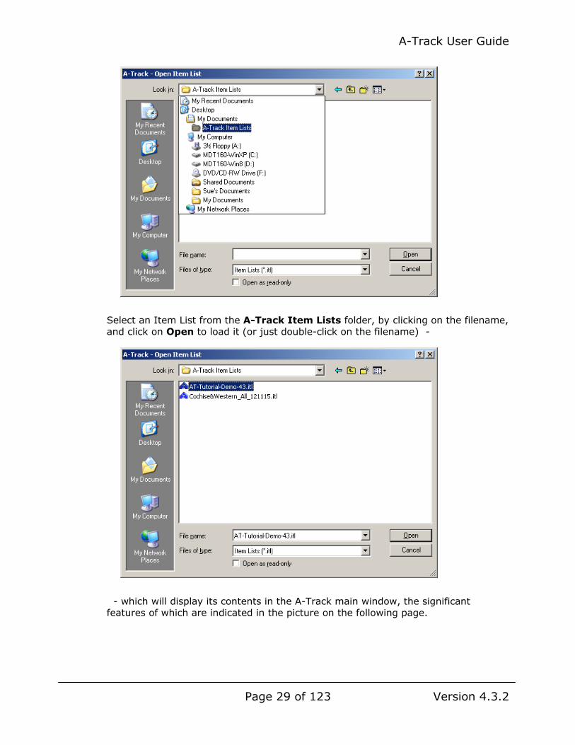
In the standard File Open window which then appears, locate the folder containing the copied Item List(s). If the folder is in your Documents area, then it should be immediately visible, and can be opened, by a double-click on the folder name, to reveal the copied Item List(s). Alternatively, if you have put them somewhere else, then drop down the folder list from the ‘Look in’ listbox in Windows XP, or shown in the lefthand pane in Windows Vista, 7, or 8, and then progressively select folders and subfolders until you reach the required Item List folder (A-Track Item Lists here), which is then opened with a double-click –
A-Track User Guide
Page 29 of 123 Version 4.3.2
Select an Item List from the A-Track Item Lists folder, by clicking on the filename, and click on Open to load it (or just double-click on the filename) -
- which will display its contents in the A-Track main window, the significant features of which are indicated in the picture on the following page.

A-Track User Guide
Page 30 of 123 Version 4.3.2
Be aware that, whenever an Item List is loaded, and you are connected to an NCE Power Pro Command Station (but not to an NCE Power Cab or Smart Booster), a fresh scan of the status of connected NCE Handheld Cabs is launched, so that the middle connection status indicator will first show red, before eventually turning yellow, then green when the scan is complete –
Note that, as an alternative to first opening the A-Track program, and then opening the Item List with which you want to work, you can simply locate the Item List file in the folder where you saved it, and then double-click on the filename. This will immediately open A-Track and load the Item List with a single action.

A-Track User Guide
Page 31 of 123 Version 4.3.2
If A-Track is already loaded, then the Item List which is double-clicked will replace any Item List which is currently open in A-Track. You will be prompted to save any changes which might have been made to the currently-open Item list before it is replaced.
Once an Item List is loaded, the pathname of the Item List file is displayed on the Status Bar at the foot of the A-track window, as shown above. If, for any reason, the Status Bar is not visible, then open the View menu (see below) and check that the Status Bar entry is ticked – if not, then click on the entry to tick it and hence activate and display the Status Bar.
A-Track records the folder location of the most-recently-opened Item List so that, the next time you click Open on the File menu, A-Track will take you directly to this folder.
By default, A-Track displays a Details view of the Item List where each row shows a description and key parameters for each Item in the List. There are alternative views available which show less detail, and may be useful when trying to find a particular Item in a long Item List. Click on the View menu to access the available options -
When using the alternative views (Large Icons, Small Icons, and List, as shown below), the Arrange Icons sub-menu is employed to select the sort order of the displayed Items. Click on one of the sub-menu options (such as by Primary Address) to sort the Item List using this Item parameter. Clicking the same sub-menu option again will re-sort the Items in the opposite sense, ie. the List will change from ascending order to descending order, or vice versa.
In the Details view you can sort the Items simply by clicking on the heading text at the top of each column for the categories shown. Having clicked on a column header, clicking again on the same header will reverse the Item sort order.
A-Track will arrange all subsequently loaded Item Lists using the View settings you select until you pick a different view. You can change the width of each column in the Details view to suit your own preferences – use the standard Windows technique

A-Track User Guide
Page 32 of 123 Version 4.3.2
of clicking on, and then dragging, the boundary between each column header to the left or right as required.
Note that the following icons are used to identify different types of Items –
Of those View menu options not covered so far, Toolbar simply enables display of the row of command icons located immediately below the Menu Bar (each icon corresponds to a selected option from one of the A-Track menus). Clicking Toolbar will disable display of the icons, removing the tick beside the option. Click again to re-enable display of the Toolbar.
Show Checked Items only displays those Items where the checkbox to the left of the Item has been clicked to show a tick. It is useful when selecting a subset of Items from a long List in order to check whether all required Items have been marked. Click the option again to re-enable display of the complete Item List.
Consist Status – Item List / Cmnd Stn allows you to review all of the consists currently defined in the Item List and an NCE Power Pro Command Station, if connected. Full details are covered in Section 5.12 of the Reference Manual.
Consist Status – View Backup File is only relevant if you have backed up Consist data from an NCE Power Pro Command Station to a file stored on your computer. If so, you can then review all of the consists held in the file with those currently in the Item List. Full details are covered in Sections 5.12 and 7.3 of the Reference Manual.
Refresh Item Allocation & Status or the Refresh ( ) button on the A-Track toolbar allows you to update the displayed Cab allocation and status.
In the standard A-Track installation, automatic status updates of the NCE Cabs attached to the Command Station are disabled by default. However, you can update the displayed Cab allocation and status at any time by clicking the Refresh ( ) button on the A-Track toolbar or by clicking on View on the A-Track menu bar, followed by Refresh Item Allocation & Status.
When you use the View menu option, you will be asked whether you wish the periodic scan of attached NCE Cabs to resume –
Locomotive
Multiple – Lead Loco (Loco assigned to a Consist)
Consist (Group of Locos)
Multiple – Mid Loco
Accessory (Turnouts or Signals) Multiple – Rear Loco

A-Track User Guide
Page 33 of 123 Version 4.3.2
Click Yes to enable future automatic scans of NCE Cab status, or No to leave the scans disabled. Leaving scans disabled is preferred if you want to adjust the setup of the NCE Power Pro Command Station or Cabs, or change Consist or Macro settings without being interrupted periodically. Further details of the way in which the NCE System Status data is handled can be found in Chapter 7 of the Reference Manual.
A tick mark next to the Refresh Item Allocation & Status option on the View menu will be displayed to indicate that periodic scans of attached NCE Cabs are enabled. In this state, every 6 minutes, A-Track will automatically re-scan the status of the NCE Cabs attached to the Command Station. The current Cab allocation and status will be cleared from the Item List, with the middle indictor on the status bar returning to show red, then changing to yellow and eventually back to green when the full re-scan has been completed.
Your choice of whether to enable or disable periodic scans of attached NCE Cabs is saved by A-Track and will be applied each time the program is started.
Note that, regardless of the setting of the automatic status update option, the Cab allocation and status will be updated each time a new Item List is loaded, or when changes are made through A-Track to the allocation of Items to attached Cabs (See Section 3.6).
3.2 Item List Load and Save Options
As introduced in the preceding section, all Item List Load and Save operations can be performed using the functions available from the File menu, some of which have alternative access via keyboard shortcuts and/or toolbar icons (see Section 8.1 for full details). As an example, you can click the icon on the Toolbar to load (Open) an Item List, or press Ctrl+O on the keyboard (hold down either Ctrl (Control) key and then press the O key) to perform the same operation.
Once an Item List has been opened, its filename is added to the Most Recently Used (MRU) list on the File menu as shown below. Up to eight filenames can be displayed in the list – when you open the ninth distinct Item List then the oldest filename is dropped from the list to make way for that of the latest Item List.

A-Track User Guide
Page 34 of 123 Version 4.3.2
Once an Item List appears in the File menu MRU list, you can open this Item List at any subsequent time simply by clicking on its filename in the MRU list, without having to go through the standard File Open window.
As well as opening an existing Item List, you can use the File menu to generate a completely new List by clicking on New (or the icon on the Toolbar, or by pressing Ctrl+N on the keyboard), which creates an Item List containing a single Blank Item. If an Item List is already loaded and has been changed in any way, then you are asked whether you wish to save the current Item List before it is replaced with the new List –
Having generated a single Blank Item, the next thing to do is to change it into a valid DCC Item having an Item Type of Locomotive, Consist, or Accessory. You should also give the Item a unique Description and Address. The sequence of operations to perform these actions has already been introduced in Section 2.3, and is covered in more detail in Section 5.2 of the Reference Manual.
When you have finished adding to the Item List, or editing individual Items (see Chapter 4), you can save the finished Item List to disk by clicking Save As on the File menu (or the icon on the Toolbar, or by pressing Ctrl+S on the keyboard), to open the standard File Save window, as shown for Windows XP below –

A-Track User Guide
Page 35 of 123 Version 4.3.2
A-Track opens the folder from which the last Item List was opened (or your main Documents or My Documents folder if no Item Lists have yet been opened), and generates a default filename, which includes today’s date, as shown.
If you wish to save the Item List under a different filename, click in the File name textbox to highlight its contents, then simply type the new filename to replace the displayed filename. Click Save to save the Item List under the given filename, which will have a file extension of .itl added to identify to Windows that the file is an A-Track Item List.
Note, however, that if you have chosen to save the edited Item List under a filename which is the same as that of a file already in the selected folder, then Windows will display a warning –
- and it is your choice on how you wish to proceed – click Yes to replace (overwrite) the file with a new version, or No to return to the Save Item List window where you can either rename the file, or select a different folder in which to save it (or abandon the whole Save As operation).
Rather than save a complete Item List to a file, A-Track also offers the capability to save only selected Items from the List. To choose the Items to save to a file, click to tick the checkbox located to the left of each Item which you wish to include, then click on Save Checked on the File menu (or the icon on the Toolbar).

A-Track User Guide
Page 36 of 123 Version 4.3.2
In the File Save window which then opens, type an appropriate filename for the reduced Item list, and click Save. You could, of course, just use the existing filename but by doing so you will overwrite the existing Item List and permanently lose all of those Items which were NOT checked – so make very sure that you really want to eliminate them.
If you maintain a number of separate small Item Lists stored on disk, then you can use A-Track to amalgamate them into a single large Item List, perhaps for archiving or back-up purposes. Do this by clicking on Open Merge on the File menu (or use the icon on the Toolbar, or press Ctrl+M on the keyboard) after you have opened the first Item List in A-Track. This will display the standard File Open window, just as for Open (see Section 3.1 and above), to allow you to select a second Item List. Opening this Item List will add its Items to the end of the first Item List.
While merged Item Lists have the same structure and format as any other Item List, and can be stored with the same .itl file extension, you may like to treat them as a master or reference List, or Item Archive. For convenience, A-Track provides the facility to use a different file extension, .ita, for any large, or merged, Item List that you wish to treat as an Item Archive.
After you have created a merged Item List or Archive you can add further Item Lists to it at any time using Open Merge, or extract smaller Item Lists from it by using the Save Checked option.
While there is nothing to stop you saving your merged file (under a different filename, of course) in the same folder as your other Item Lists, it is a good idea to create a separate folder to hold such merged Lists especially if they are to be regarded as Archives. Start by opening the File menu, and clicking on Save As.
If using Windows XP, in the Save Item List dialog window which opens, locate a suitable parent folder (such as My Documents) using the drop-down Save in: listbox –

A-Track User Guide
Page 37 of 123 Version 4.3.2
Double-click on the parent folder to open it, then use the Create New Folder button on the File Save window toolbar, as shown below. Type in a suitable name for the new folder, click Open to open it, then click again on the same button (now labelled Save) to save the Item List using either the suggested filename based on today’s date, Merged-ItemList-16-May-13 here, or one which is more meaningful to yourself, together with the .ita extension, selected from the Save as type: drop-down listbox –
A-Track User Guide
Page 38 of 123 Version 4.3.2
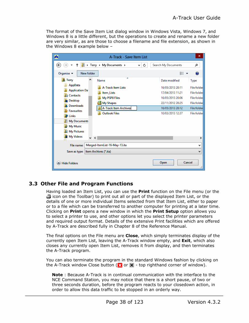
The format of the Save Item List dialog window in Windows Vista, Windows 7, and Windows 8 is a little different, but the operations to create and rename a new folder are very similar, as are those to choose a filename and file extension, as shown in the Windows 8 example below –
3.3 Other File and Program Functions
Having loaded an Item List, you can use the Print function on the File menu (or the icon on the Toolbar) to print out all or part of the displayed Item List, or the
details of one or more individual Items selected from that Item List, either to paper or to a file which can be transferred to another computer for printing at a later time. Clicking on Print opens a new window in which the Print Setup option allows you to select a printer to use, and other options let you select the printer parameters and required output format. Details of the extensive Print facilities which are offered by A-Track are described fully in Chapter 8 of the Reference Manual.
The final options on the File menu are Close, which simply terminates display of the currently open Item List, leaving the A-Track window empty, and Exit, which also closes any currently open Item List, removes it from display, and then terminates the A-Track program.
You can also terminate the program in the standard Windows fashion by clicking on the A-Track window Close button ( or - top righthand corner of window).
Note : Because A-Track is in continual communication with the interface to the NCE Command Station, you may notice that there is a short pause, of two or three seconds duration, before the program reacts to your closedown action, in order to allow this data traffic to be stopped in an orderly way.
A-Track User Guide
Page 39 of 123 Version 4.3.2
With any of the terminate options, if the Item List has been changed in any way, you are asked whether you wish to save the current Item List before it is closed -
Selecting Yes allows you to save the changed Item List under your choice of filename, clicking No will immediately close the Item List and cause any changes to be discarded (permanently lost), while Cancel will abandon the Close or Exit process and return you to A-Track with the current Item List still displayed intact.
3.4 Editing - Undo, Redo, Find, and Selection
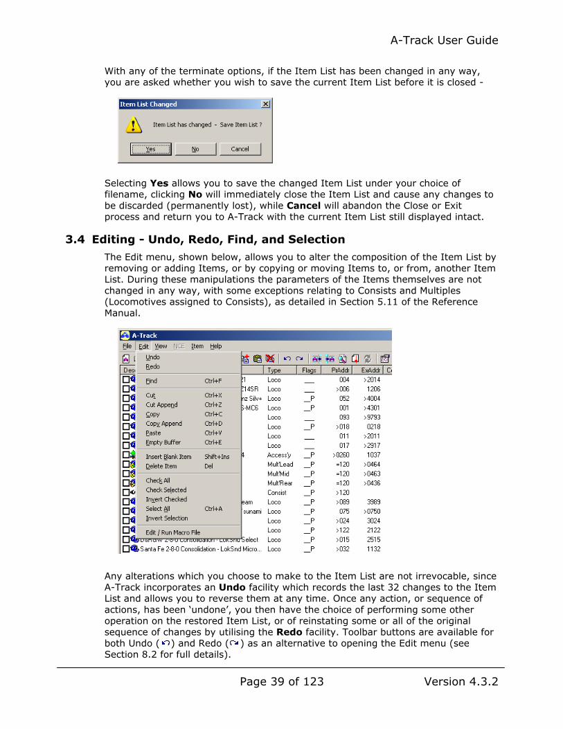
The Edit menu, shown below, allows you to alter the composition of the Item List by removing or adding Items, or by copying or moving Items to, or from, another Item List. During these manipulations the parameters of the Items themselves are not changed in any way, with some exceptions relating to Consists and Multiples (Locomotives assigned to Consists), as detailed in Section 5.11 of the Reference Manual.
Any alterations which you choose to make to the Item List are not irrevocable, since A-Track incorporates an Undo facility which records the last 32 changes to the Item List and allows you to reverse them at any time. Once any action, or sequence of actions, has been ‘undone’, you then have the choice of performing some other operation on the restored Item List, or of reinstating some or all of the original sequence of changes by utilising the Redo facility. Toolbar buttons are available for both Undo ( ) and Redo ( ) as an alternative to opening the Edit menu (see Section 8.2 for full details).

A-Track User Guide
Page 40 of 123 Version 4.3.2
As well as restoring the structure of the whole Item List, you can also employ the Undo function to reverse any changes that you have made to the parameters or Configuration Variables of individual Items through the facilities described later in Chapter 4. If, immediately after making alterations to an Item’s parameters and evaluating its new characteristics on the track, you want to return the Item to its original state, then simply click Undo on the Edit menu, or the Undo icon on the toolbar. The edits made to the Item’s parameters will then be ‘undone’, assuming that you have not made any other changes to the Item List in the meantime – if so, you will have to undo these subsequent changes before the desired Item is restored (and then make the subsequent changes to the Item List again, if necessary).
Note carefully, however, that restoring an Item’s CVs to their original value in the Item List does not change the corresponding values in the real, physical DCC decoder in your locomotive or accessory. To do that, you will have to program (or re-program) the restored values into the actual decoder on the track, as explained in detail in Section 4.9.
The next function on the Edit menu, Find (also available through the icon on the Toolbar) acts as an aid which allows you, particularly when dealing with large Item Lists, to search the complete Item List for particular Items. Click to display the Find Item window, then simply type any combination of letters or numbers that you believe are in the Description or Address (Primary or Extended) of the required Item(s) - your text will replace the prompt in the textbox –
Select whether to search Item Descriptions or Addresses, or both (but selecting none will disable the Find operation), choose to search either Upwards (from the currently-selected Item towards the beginning of the Item List) or Downwards (from the current Item towards the end of the Item List), then click the Find button.
The first Item found whose Description or Address contains the entered search characters will then be highlighted in the Item List. Note, however, that if the currently highlighted Item matches the search criterion, then the Item highlight will not move – and you may think, incorrectly, that the Find operation has failed.
Click the Next button, as shown in the example below, to continue the search for the next Item (if any) which contains your search characters, or Close or Finish to terminate the Find operation, leaving the last found Item highlighted. If no further matching Items are found, then only the Finish button will be enabled to quit the operation (this will also be the case where no matching Items at all are located).

A-Track User Guide
Page 41 of 123 Version 4.3.2
If you wish, you can move the Find Item window out of the way, so that it does not obscure any of the Item List details, by clicking on its title bar, holding down the left mouse button, and dragging the window to a convenient part of the screen. The Find Item window will remain on the screen, in front of the main A-Track window, until you click on the Close or Finish button, and does not interfere with any other A-Track or Item operations. Hence, having found a matching Item, you can examine its parameters in detail (see Section 4.1) to check if it is the Item you require, before resuming the search of the Item List.
At any point in using the Find Item function you can change any of the search parameters, or click on any Item in the Item List to define a new starting point for a revised search. After any such changes, click Next to restart the Find operation. Note that you can also do this by simply pressing the Enter/Return key – although be aware that, when the Finish button becomes active at the end of a search, the Enter/Return key will, instead, close the Find Item window.
3.5 Editing - Cut, Copy, and Paste
To facilitate copying and moving Items between Item Lists, A-Track incorporates a private storage area known as the Copy Buffer. Copies of selected Items are moved into, and taken from, the Copy Buffer by using the Cut, Copy, and Paste operations on the Edit menu.
To select an Item which is to be the target of one of these Edit operations, click on it – the whole Item row is then highlighted. To select a group of Items, click on the first Item in the group, hold down either Shift ( ) key, and click on the last Item in the group. Single Items can be added to a selected group (which may just be one other selected Item) by clicking on the Item to be added while either Ctrl (Control) key is held down. Conversely, clicking on a selected Item while holding down either Ctrl key will deselect that Item and remove its highlighting.
Once one or more Items have been selected, you can use either Cut or Copy to place copies of the selected Items in the Copy Buffer.
Note that, when any Edit CVs window is open, the whole Edit menu is disabled, together with the Delete Item, Cut, Cut Append, and Copy Append entries on the Pop-Up menu, and all of the relevant Toolbar icons. Hence, if you are unable to access the Item List Edit features, check first that all Edit CVs windows have been closed.
Cut (the icon on the Toolbar) removes the selected Items from the Item List, ie. it moves the Items to the Buffer, where the moved Items replace any previous contents of the Copy Buffer. Copy ( ), on the other hand leaves the Items in the

A-Track User Guide
Page 42 of 123 Version 4.3.2
Item list, ie. it simply copies the Items, although the copied Items still replace any previous contents of the Copy Buffer.
If you wish to add selected Items, or copies of the selected Items, to the Items which are already in the Copy Buffer, then use either Cut Append ( ) or Copy Append ( ). These operations work in essentially the same way as Cut and Copy, respectively, but the Items moved or copied are added to any previous contents of the Copy Buffer, instead of replacing or overwriting them. This allows you to select the Items you wish to copy or transfer in several stages rather than attempting to perform the operation in a single step.
When you have all of the required Items in the Copy Buffer, you then use Paste ( ) to place all of the copied Items back into an Item List. The copied Items are added to the end of the current Item List file being displayed by A-Track unless you have chosen to sort the Item list by one of the Item parameters, in which case they will be inserted at an appropriate position in the List determined by the sort order. This can cause you to lose track of some of the copied Items when pasting in a sizeable group of Items, so that you are recommended to sort the Item List by File Order (either via the View / Arrange Items menu, or the icon on the Toolbar) before (or after) executing the Paste operation. The pasted Items can then all be found together at the end (bottom) of the List.
If you Paste the Items back into the same Item List as they were taken from, then you will have a set of duplicated Items. While this is perfectly allowable (and A-Track treats such duplicates as different Items even though their parameters are identical) it can lead to problems subsequently, when you are never going to be sure which duplicate Item is the one to be edited or controlled. Hence, the recommendation is to change at least the Address of each duplicate Item immediately – and preferably their Descriptions also – to eliminate any confusion.
Creating duplicate Items is a useful shortcut when you are adding a new Item to your roster which is very similar to one that you already have there, and can save a lot of time in setting up all of the Configuration Variables (CVs) and other parameters for the new Item.
Important Note : When using Cut, Copy, and Paste operations on Items which are either Consists or Multiples (Locomotives assigned to a Consist) you need to be aware that the links within and between such Items require them to be handled in a special way. See Section 4.5 of the Reference Manual (or the Help Topic on ‘Editing - Cut, Copy, and Paste’) for full details.
If you make a mistake when using Cut, Copy, or Paste remember that you can easily put the Item List back to the state it was in previously by using the Undo function described in Section 3.4 – always bearing in mind that Undo only records the last 32 Edit actions performed on the Item List (although each Edit action can include any number of Items).
With a selected set of Items in the Copy Buffer, you can transfer them to either another existing Item List, or you can create a new Item List to hold them. Do this either by clicking on File / Open to open an existing List, or on File / New to create a new Item List with one Blank Item, and in either case saving the current Item List if necessary, when prompted.

A-Track User Guide
Page 43 of 123 Version 4.3.2
The contents of the Copy Buffer are then added to the newly-displayed Item List by clicking Paste. A typical sequence of actions is shown below for the case of a completely new Item List.
First, select and Copy (or Cut) a set of Items –
Next, close the Item List (using File/Close), dealing appropriately with any prompt to save the List if it has been changed, then open a new List with one Blank Item (using File/New), and click Paste -
- to add the copied (or cut) Items from the Copy Buffer to the new Item List -
The Blank Item can either be converted into a valid Item in its own right (see Section 2.3, or Section 5.2 of the Reference Manual)), or simply removed by using either Delete from the Edit menu, or the button on the Toolbar, or just by pressing the Delete key on the keyboard, with the Blank Item highlighted (as above).
Important : using the Delete operation does not copy any deleted Items to the Copy Buffer, although you can restore such Items using Undo if they were deleted in error.
Note, however, that if you Delete a Consist, then any assigned Multiples are also deleted, but immediately converted to Locomotives, and then pasted back into the Item List.
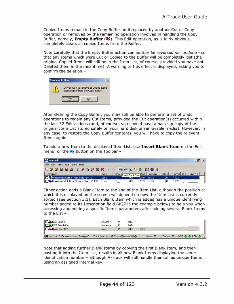
A-Track User Guide
Page 44 of 123 Version 4.3.2
Copied Items remain in the Copy Buffer until replaced by another Cut or Copy operation or removed by the remaining operation involved in handling the Copy Buffer, namely, Empty Buffer ( ). This Edit operation, as is fairly obvious, completely clears all copied Items from the Buffer.
Note carefully that the Empty Buffer action can neither be reversed nor undone - so that any Items which were Cut or Copied to the Buffer will be completely lost (the original Copied Items will still be in the Item List, of course, provided you have not Deleted them in the meantime). A warning to this effect is displayed, asking you to confirm the deletion –
After clearing the Copy Buffer, you may still be able to perform a set of Undo operations to regain any Cut Items, provided the Cut operation(s) occurred within the last 32 Edit actions (and, of course, you should have a back-up copy of the original Item List stored safely on your hard disk or removable media). However, in any case, to restore the Copy Buffer contents, you will have to copy the relevant Items again.
To add a new Item to the displayed Item List, use Insert Blank Item on the Edit menu, or the button on the Toolbar –
Either action adds a Blank Item to the end of the Item List, although the position at which it is displayed on the screen will depend on how the Item List is currently sorted (see Section 3.1). Each Blank Item which is added has a unique identifying number added to its Description field (#27 in the example below) to help you when accessing and editing a specific Item’s parameters after adding several Blank Items to the List –
Note that adding further Blank Items by copying the first Blank Item, and then pasting it into the Item List, results in all new Blank Items displaying the same identification number – although A-Track will still handle them all as unique Items using an assigned internal key.
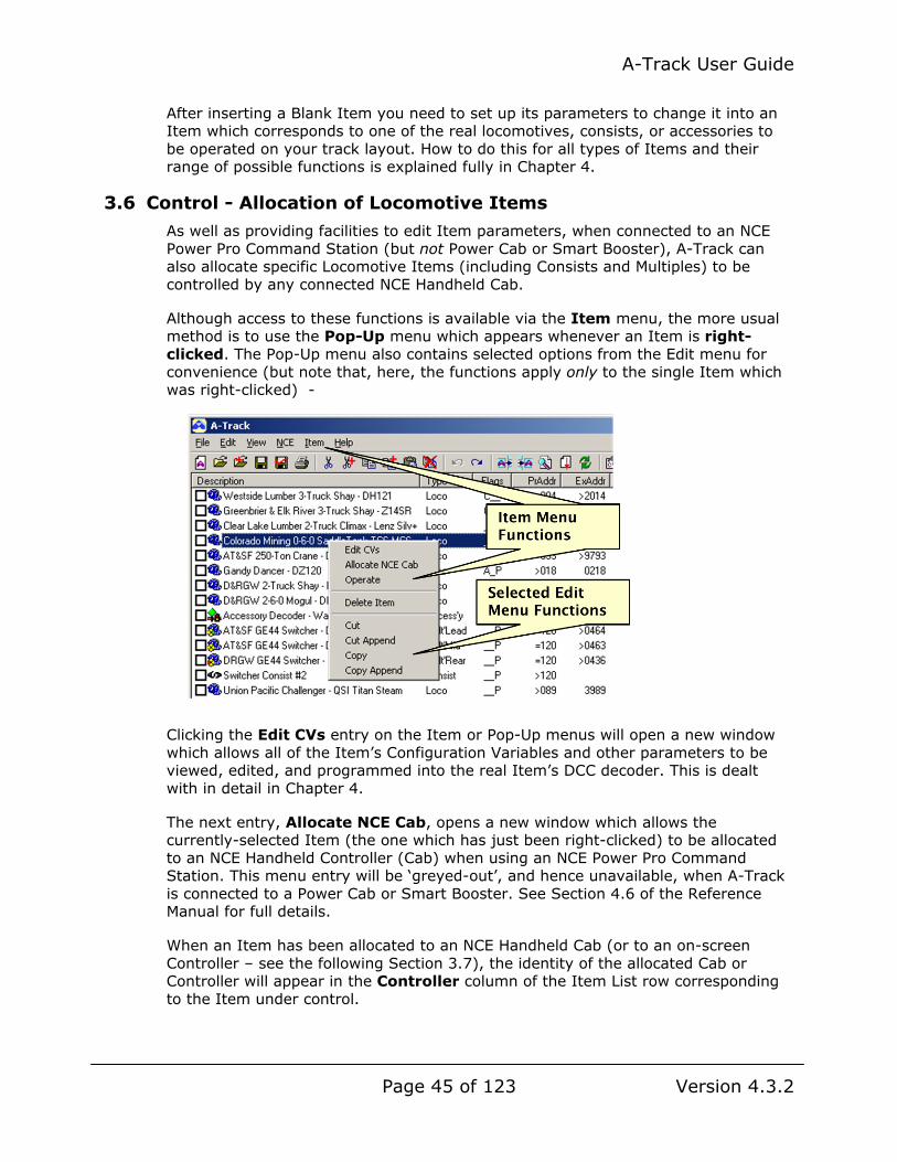
A-Track User Guide
Page 45 of 123 Version 4.3.2
After inserting a Blank Item you need to set up its parameters to change it into an Item which corresponds to one of the real locomotives, consists, or accessories to be operated on your track layout. How to do this for all types of Items and their range of possible functions is explained fully in Chapter 4.
3.6 Control - Allocation of Locomotive Items
As well as providing facilities to edit Item parameters, when connected to an NCE Power Pro Command Station (but not Power Cab or Smart Booster), A-Track can also allocate specific Locomotive Items (including Consists and Multiples) to be controlled by any connected NCE Handheld Cab.
Although access to these functions is available via the Item menu, the more usual method is to use the Pop-Up menu which appears whenever an Item is right-clicked. The Pop-Up menu also contains selected options from the Edit menu for convenience (but note that, here, the functions apply only to the single Item which was right-clicked) -
Clicking the Edit CVs entry on the Item or Pop-Up menus will open a new window which allows all of the Item’s Configuration Variables and other parameters to be viewed, edited, and programmed into the real Item’s DCC decoder. This is dealt with in detail in Chapter 4.
The next entry, Allocate NCE Cab, opens a new window which allows the currently-selected Item (the one which has just been right-clicked) to be allocated to an NCE Handheld Controller (Cab) when using an NCE Power Pro Command Station. This menu entry will be ‘greyed-out’, and hence unavailable, when A-Track is connected to a Power Cab or Smart Booster. See Section 4.6 of the Reference Manual for full details.
When an Item has been allocated to an NCE Handheld Cab (or to an on-screen Controller – see the following Section 3.7), the identity of the allocated Cab or Controller will appear in the Controller column of the Item List row corresponding to the Item under control.
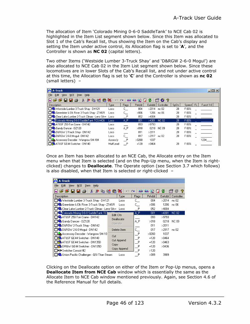
A-Track User Guide
Page 46 of 123 Version 4.3.2
The allocation of Item ‘Colorado Mining 0-6-0 SaddleTank’ to NCE Cab 02 is highlighted in the Item List segment shown below. Since this Item was allocated to Slot 1 of the Cab’s Recall list, thus showing the Item on the Cab’s display and setting the Item under active control, its Allocation flag is set to ‘A’, and the Controller is shown as NC 02 (capital letters).
Two other Items (‘Westside Lumber 3-Truck Shay’ and ‘D&RGW 2-6-0 Mogul’) are also allocated to NCE Cab 02 in the Item List segment shown below. Since these locomotives are in lower Slots of the Cab’s Recall list, and not under active control at this time, the Allocation flag is set to ‘C’ and the Controller is shown as nc 02 (small letters) –
Once an Item has been allocated to an NCE Cab, the Allocate entry on the Item menu when that Item is selected (and on the Pop-Up menu, when the Item is right-clicked) changes to Deallocate. The Operate option (see Section 3.7 which follows) is also disabled, when that Item is selected or right-clicked –
Clicking on the Deallocate option on either of the Item or Pop-Up menus, opens a Deallocate Item from NCE Cab window which is essentially the same as the Allocate Item to NCE Cab window mentioned previously. Again, see Section 4.6 of the Reference Manual for full details.
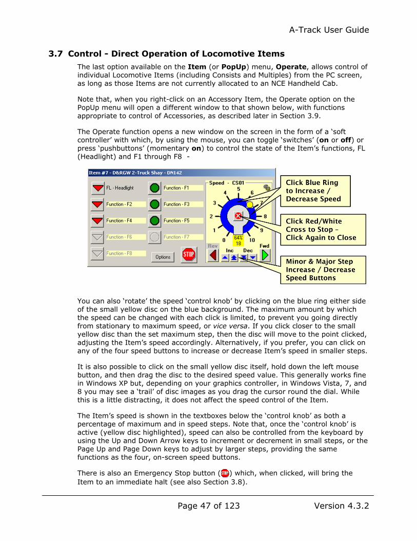
A-Track User Guide
Page 47 of 123 Version 4.3.2
3.7 Control - Direct Operation of Locomotive Items
The last option available on the Item (or PopUp) menu, Operate, allows control of individual Locomotive Items (including Consists and Multiples) from the PC screen, as long as those Items are not currently allocated to an NCE Handheld Cab.
Note that, when you right-click on an Accessory Item, the Operate option on the PopUp menu will open a different window to that shown below, with functions appropriate to control of Accessories, as described later in Section 3.9.
The Operate function opens a new window on the screen in the form of a ‘soft controller’ with which, by using the mouse, you can toggle ‘switches’ (on or off) or press ‘pushbuttons’ (momentary on) to control the state of the Item’s functions, FL (Headlight) and F1 through F8 -
You can also ‘rotate’ the speed ‘control knob’ by clicking on the blue ring either side of the small yellow disc on the blue background. The maximum amount by which the speed can be changed with each click is limited, to prevent you going directly from stationary to maximum speed, or vice versa. If you click closer to the small yellow disc than the set maximum step, then the disc will move to the point clicked, adjusting the Item’s speed accordingly. Alternatively, if you prefer, you can click on any of the four speed buttons to increase or decrease Item’s speed in smaller steps.
It is also possible to click on the small yellow disc itself, hold down the left mouse button, and then drag the disc to the desired speed value. This generally works fine in Windows XP but, depending on your graphics controller, in Windows Vista, 7, and 8 you may see a ‘trail’ of disc images as you drag the cursor round the dial. While this is a little distracting, it does not affect the speed control of the Item.
The Item’s speed is shown in the textboxes below the ‘control knob’ as both a percentage of maximum and in speed steps. Note that, once the ‘control knob’ is active (yellow disc highlighted), speed can also be controlled from the keyboard by using the Up and Down Arrow keys to increment or decrement in small steps, or the Page Up and Page Down keys to adjust by larger steps, providing the same functions as the four, on-screen speed buttons.
There is also an Emergency Stop button ( ) which, when clicked, will bring the Item to an immediate halt (see also Section 3.8).

A-Track User Guide
Page 48 of 123 Version 4.3.2
Direction ‘switches’ are provided to change the Item’s direction of travel from Forward to Reverse, or vice versa.
As well as altering the state of an Item function, by clicking on a ‘toggle switch’ or ‘pushbutton’ you also get visual feedback that the action has been recognised, as shown below -
The behaviour of the function ‘switches’ and the speed ‘control knob’ can be programmed to suit the requirements of the Item and your personal preferences. To adjust the settings, first Stop the Item by clicking on the red/white cross ( ) in the centre of the speed ‘control knob’, then click on the Options button. If you click Options without first stopping the Item, then you will receive a warning –
- click Yes to continue, or No to abandon the action.
With the Item stopped, the Operate window changes to reveal the options which are available for you to customise –
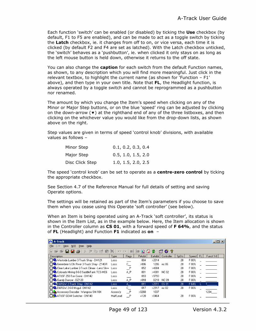
A-Track User Guide
Page 49 of 123 Version 4.3.2
Each function ‘switch’ can be enabled (or disabled) by ticking the Use checkbox (by default, F1 to F5 are enabled), and can be made to act as a toggle switch by ticking the Latch checkbox, ie. it changes from off to on, or vice versa, each time it is clicked (by default F2 and F4 are set as latched). With the Latch checkbox unticked, the ‘switch’ behaves as a ‘pushbutton’, ie. when clicked it only stays on as long as the left mouse button is held down, otherwise it returns to the off state.
You can also change the caption for each switch from the default Function names, as shown, to any description which you will find more meaningful. Just click in the relevant textbox, to highlight the current name (as shown for ‘Function – F1’ above), and then type in your own title. Note that FL, the Headlight function, is always operated by a toggle switch and cannot be reprogrammed as a pushbutton nor renamed.
The amount by which you change the Item’s speed when clicking on any of the Minor or Major Step buttons, or on the blue ‘speed’ ring can be adjusted by clicking on the down-arrow ( ) at the righthand end of any of the three listboxes, and then clicking on the whichever value you would like from the drop-down lists, as shown above on the right.
Step values are given in terms of speed ‘control knob’ divisions, with available values as follows –
Minor Step 0.1, 0.2, 0.3, 0.4
Major Step 0.5, 1.0, 1.5, 2.0
Disc Click Step 1.0, 1.5, 2.0, 2.5
The speed ‘control knob’ can be set to operate as a centre-zero control by ticking the appropriate checkbox.
See Section 4.7 of the Reference Manual for full details of setting and saving Operate options.
The settings will be retained as part of the Item’s parameters if you choose to save them when you cease using this Operate ‘soft controller’ (see below).
When an Item is being operated using an A-Track ‘soft controller’, its status is shown in the Item List, as in the example below. Here, the Item allocation is shown in the Controller column as CS 01, with a forward speed of F 64%, and the status of FL (Headlight) and Function F1 indicated as on –

A-Track User Guide
Page 50 of 123 Version 4.3.2
To exit from the Operate function, first switch all functions off, then stop the Item either by using the on-screen or keyboard controls to reduce its speed to zero or by clicking the red/white cross ( ) in the centre of the control knob. A further click on the red/white cross will then close the Operate window – with a prompt to save the control settings within the Item, if they have been changed -
Two final points to note in connection with the control of Items directly from A-Track are that, firstly, while any Item is being operated from the screen, you cannot change or edit the Item List. All relevant File menu options, such as New, Open, and Close, and the complete Edit menu, are disabled until you cease direct Item control and close all Operate windows.
Secondly, if you attempt to close the complete A-Track program while Items are still under the control of a ‘soft controller’, then a warning will be displayed –
Clicking Cancel will return you to A-Track, with the opportunity to stop and deallocate the Items still under control, or you can click OK to force an immediate stop and disconnect of all Items. The latter operation is performed by issuing an Emergency Stop via the NCE Command Station, followed (only if you are using an NCE Power Pro system) by a short disconnection of mainline track power, before the A-Track program is finally closed.
3.8 Emergency Stop
The last control in the Operate window, which was not dealt with in the previous section, is the Emergency Stop button which, when clicked, activates an Emergency Stop of the Item under control, cancels all active function ‘switches’, and sets the speed ‘control knob’ to zero. A Stop icon ( ) replaces the normal Active indicator ( ) in the top-righthand corner of the Operate window, as shown below –

A-Track User Guide
Page 51 of 123 Version 4.3.2
Any subsequent click on a function ‘switch’ or ‘pushbutton’, or movement of the speed ‘control knob’ will cancel the Emergency Stop of the Item, and remove the Stop icon.
However, a second click on the Operate window Stop button of the stopped Item will apply an Emergency Stop to all Items currently on the mainline track, by sending a continuous set of Emergency Stop All commands for a period of about 4 seconds.
Note : An Emergency Stop can also be generated from any of the NCE Cabs which are currently connected to the NCE Cab Bus, but A-Track is not aware that such an Emergency Stop has been activated, and normal track operation can then only be resumed from the activating NCE Cab
If you are connected to an NCE Power Pro Command Station, generating an Emergency Stop from A-Track sends an advisory message ‘AT-E’STP’ to the LCD display of all attached NCE ProCabs, to make all operators aware of what has happened, together with a warning message displayed on the PC screen –
Clicking on Resume cancels the Emergency Stop of all Items, although each Item will remain stationary on the track until a new speed command is sent from the Controller to which that Item is allocated.
Note that Items under the control of an NCE Cab can be restarted as soon as the string of Emergency Stop All commands finishes, and without the Resume button being clicked, although it would be sensible to check on why an Emergency Stop was activated before continuing with track operations. The A-Track advisory message can be removed from the LCD display of any NCE ProCab by pressing the Cab’s ENTER key.
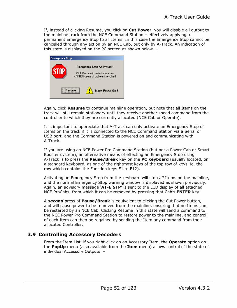
A-Track User Guide
Page 52 of 123 Version 4.3.2
If, instead of clicking Resume, you click on Cut Power, you will disable all output to the mainline track from the NCE Command Station – effectively applying a permanent Emergency Stop to all Items. In this case the Emergency Stop cannot be cancelled through any action by an NCE Cab, but only by A-Track. An indication of this state is displayed on the PC screen as shown below –
Again, click Resume to continue mainline operation, but note that all Items on the track will still remain stationary until they receive another speed command from the controller to which they are currently allocated (NCE Cab or Operate).
It is important to appreciate that A-Track can only activate an Emergency Stop of Items on the track if it is connected to the NCE Command Station via a Serial or USB port, and the Command Station is powered on and communicating with A-Track.
If you are using an NCE Power Pro Command Station (but not a Power Cab or Smart Booster system), an alternative means of effecting an Emergency Stop using A-Track is to press the Pause/Break key on the PC keyboard (usually located, on a standard keyboard, as one of the rightmost keys of the top row of keys, ie. the row which contains the Function keys F1 to F12).
Activating an Emergency Stop from the keyboard will stop all Items on the mainline, and the normal Emergency Stop warning window is displayed as shown previously. Again, an advisory message ‘AT-E’STP’ is sent to the LCD display of all attached NCE ProCabs, from which it can be removed by pressing that Cab’s ENTER key.
A second press of Pause/Break is equivalent to clicking the Cut Power button, and will cause power to be removed from the mainline, ensuring that no Items can be restarted by an NCE Cab. Clicking Resume in this state will send a command to the NCE Power Pro Command Station to restore power to the mainline, and control of each Item can then be regained by sending the Item any command from their allocated Controller.
3.9 Controlling Accessory Decoders
From the Item List, if you right-click on an Accessory Item, the Operate option on the PopUp menu (also available from the Item menu) allows control of the state of individual Accessory Outputs –

A-Track User Guide
Page 53 of 123 Version 4.3.2
Clicking Operate opens a new window on the screen in the form of a ‘soft controller’, similar to that described in Section 3.7 for Locomotive Items, which, by use of the mouse to click the relevant buttons, lets you issue commands to switch the state of the Accessory Outputs, together with some additional functions –
The example above shows the controls for an NCE Switch-8 accessory decoder with eight Outputs, opened as Controller CS01. Each Output has a customisable label (set by default to be ‘Output 1’ through ‘Output 8’), a note of its assigned address (0129 through 0136 in this case), and two buttons to switch the state of the Output.
It is assumed that accessory decoders will be applied to operate turnouts, so the green button ( or ) will set the turnout to the Normal (Straight) position, and the red button ( or ) will set the turnout to the Route (Reverse or Thrown) position.
One button will be in a ‘bright’ state ( or ) to indicate the direction of the last command sent to the turnout, while the other button will be set to the ‘dark’ state ( or ). Hence, in the example above, Outputs 2, 4, 5, and 7 are set to Route, while Outputs 1, 3, 6, and 8 are in the Normal state.
These states can be seen in the Function column of the Item List in Details view, where an Output set to Normal will be shown as ‘0’, and one set to Route will have the Output number displayed –

A-Track User Guide
Page 54 of 123 Version 4.3.2
Accessory Items which represent decoders with less than eight Outputs will only have status numbers shown for those Outputs which exist, with the other, unused Function columns displaying an underscore (_) symbol, as shown above.
The NCE Power Pro Command Station maintains a record of the last command sent to all turnout addresses from either A-Track or any Handheld Cab. This data is loaded by A-Track from the Command Station (at the same time as Consist data) each time the program is started. All turnout status data is also reloaded each time an Accessory ‘soft controller’ is opened by clicking Operate (not just the data for the turnouts associated with that Item).
Hence, as soon as an Item List is loaded, the Output status relevant to each Accessory Item will be displayed in the Function column of the Details view. If no command has ever been sent to a particular address, then the turnout is assumed, by the NCE Power Pro system, to be in the Route (Reverse or Thrown) position.
However, turnout status data is not available from an NCE Power Cab system, so in this case the Item List Function column in an Item List will only show status due to commands sent from A-Track, and subsequently saved within the Accessory Items in the Item List.
Note that the status data from either source relates only to the issued turnout commands, and does not necessarily align with the actual turnout position, which, for example, may have been altered manually at some time. Automatic, real-time monitoring of actual turnout positions is beyond the capabilities of all standard Command Stations, and would require substantial extra equipment to be installed on the layout.
The Output command buttons of the Operate ‘soft controller’ make no reference, therefore, to the status data when generating turnout commands. Clicking the green button ( or ) always sends a Normal (Straight) command, and a click on the red button ( or ) will always send a Route (Thrown) command to the turnout, via the Command Station (Power Cab or Power Pro).
To help you identify which turnout is which on the layout, without having to commit the table of assigned addresses to memory, you can attach your own label to each Accessory Output.
Returning to the example of the NCE Switch-8 accessory decoder above, click on the Options button to display the available facilities for customisation. You can change the caption for each Output from the default simple numbering, as shown, to any description which you will find more meaningful. Just click in the relevant textbox, to highlight the current name (such as ‘Output 1’ above), and then type in your own text for each caption required –

A-Track User Guide
Page 55 of 123 Version 4.3.2
In addition, if not all of the Outputs are currently used to operate turnouts on the layout, you can disable the unused Outputs by clicking to remove the tick in the associated Use checkbox, as shown above for Outputs 6, 7, and 8.
See Sections 5.14 and 5.16 of the Reference manual for full details of setting and saving Accessory Operate options.

A-Track User Guide
Page 56 of 123 Version 4.3.2
4 ITEM OPERATIONS
The characteristics of each Item in the Item List are set primarily by the values of the Configuration Variables (CVs) which are programmed into the real DCC decoder fitted within the locomotive or accessory corresponding to the Item.
You can obtain access, to set and modify the Item’s CVs, together with the various other parameters which provide a full Item definition, through either the Item or Pop-Up menus as explained in Section 3.6 (refer also to Chapter 8 for descriptions of all menu operations).
4.1 Edit Configuration Variables Window
Click on Edit CVs in either menu, or on the icon on the toolbar, or simply double-click on the Item itself in the Item List to open the Edit Configuration Variables window for the selected Item -
Note that you can open Edit CVs windows for as many Items as you wish at the same time, and work with any selected window, including the main A-Track window, while all Edit CVs windows remain on the screen. The windows can be minimised to the Task Bar, to reduce screen clutter, if required. If you have several Edit CVs windows open then, in order to see them all on the screen at the same time, make sure that the main A-Track window is not maximised – otherwise you will only see one Edit CVs window displayed on the screen (in front of the maximised A-Track window) at a time.

A-Track User Guide
Page 57 of 123 Version 4.3.2
An Edit CVs window has four distinct areas, each containing some information or parameters relating to the corresponding Item -
• Item Description - a piece of descriptive text about the Item - this can be anything you wish, up to a maximum length of 64 characters
• Parameter Tabs - a collection of tabs or pages each dealing with a set of related Item CVs or other parameters
• Action Buttons - to invoke functions related to editing CVs, transferring them between Items and DCC decoders, and saving the results back to the Item List
• CV Values - a grid showing the value held in the Item for each Configuration Variable. A CV value can lie between 000 and 255, although valid values for specific CVs can be restricted to a smaller range by the NMRA standards or by the decoder manufacturer. When opened initially, as above, the grid shows CV01 to CV128, but other ranges of CV values can be displayed when required (see Section 4.5).
When you pause the mouse cursor over any CV value in the grid, a pop-up label describing the function (if any) allocated to that CV will be displayed, as shown in the example below, where the cursor is over CV01 which holds the Item’s Primary Address –
The Edit CVs window opens showing the Item Description and the contents of the Identity Parameter Tab, as shown on the previous page. This Tab displays the Type of Item (Locomotive, in this case), and allows you to set or change the Item’s Primary and Extended Addresses (or Consist Address if the Item is a Consist or Multiple), and to enter your own values for the User Identifiers if required.
The Item Type and Primary Address, at least, must be defined before the Item becomes usable (and it is always advisable to enter a sensible Item Description, possibly with details of the fitted decoder and, in a club roster, the owner’s name or initials, before proceeding). See Section 5.1 of the Reference Manual for further details regarding Item parameters.
Besides an identifying Address, the other key parameter which must be defined before using the Item with a real decoder is the Decoder Configuration, held in Configuration Variable CV29, whose current settings can be found under the Configuration Tab.
Click on Config to reveal the tab’s contents, as shown below for a Locomotive (or Multiple) Item –

A-Track User Guide
Page 58 of 123 Version 4.3.2
You can enter the basic settings required for CV29 simply by clicking on the group of checkboxes shown under Basic Operation, which will select (tick) the required set of options for this Item. More complex configuration parameters can be accessed by selecting one of the other sets listed under Parameters (Automatic Stop, Bi-Directional Communications, or Alternate Power Source) and then selecting from the new group of checkboxes which will be displayed instead of the Basic Operation set.
For an Accessory Item, the format of the Config Tab has fewer options, as shown in the example on the left –
The basic Parameters, as defined in the NMRA DCC Standards, are simpler, with the only other configuration options allowing you to select which of the four pairs of Auxiliary inputs will operate the corresponding pair of Accessory outputs, and the time for which each pair of outputs will stay in the ‘On’ state following receipt of an activating command to the relevant Output Address (shown highlighted with a light yellow background)
Although the NMRA Standards generally assume that Accessory decoders (like those for Locomotives) will have their address, at least, programmed on a separate Program Track, most manufacturers now produce Accessory decoders which are designed to have their addresses, and any other parameters, programmed directly

A-Track User Guide
Page 59 of 123 Version 4.3.2
from the Mainline Track in conjunction with switch or special wiring settings on the decoder itself.
When you set up an Item to represent one of these modern Accessories, you should click to tick the checkbox in the Programming area labelled Manuf Specific (Program on Main Track). If this is an Accessory decoder manufactured by NCE, then tick the NCE Decoder checkbox as well. A third Parameter Tab labelled Addrs will then be displayed, and will allow you to allocate up to eight Output Addresses to the Accessory, together with several other options, as shown below for an NCE Switch-It –
Further details of how to set up addresses and parameters for Accessory Items, and then program the relevant values into the actual decoder, can be found in Sections 4.11 and 4.12.
The Edit CVs window for a Consist Item does not use any Tabs other than Identity and Config, since the detailed parameters for the Consist’s constituent Locomotives (referred to as Multiples) are stored in the Multiple Items themselves.
The Consist Config Tab shows you, in a drop-down list, which Locomotives are currently assigned to this Consist, together with controls to alter the Locomotive assignments to suit your requirements. Note, however, that a Consist Item does not possess any real Configuration Variables of its own, and that you cannot directly edit any of the values shown in the CV Value Grid –

A-Track User Guide
Page 60 of 123 Version 4.3.2
By selecting any of the assigned Locomotives listed under the Config Tab, and then clicking the Edit Loco button, you can open a new Edit CVs window displaying the parameters of the selected locomotive. If you open Edit CVs windows for all of the assigned locomotives then you can check that all of their individual parameters are consistent with each other.
In particular, ensure, under the Speed Parameter Tab, that each Locomotive uses the same Speed Step Precision (14, 28, or 128) and that their speed characteristics are matched. Matching speed characteristics, so that each locomotive runs at the same track speed for any given speed controller setting may require implementation and tailoring of one of the Speed Tables for each locomotive individually (even if they are nominally the same model from the same manufacturer). See Section 4.2 for details of Speed Table settings, and Section 4.10 for full details of how Consists are constructed and handled.
Feel free to explore all of the options available in the Edit CVs window and experiment with changing the various CV options. You cannot do any damage to the Item’s actual stored values because, in the Edit CVs window, you are only working with a temporary copy of each Item’s parameters.
As soon as you make any change to the Item’s parameters or CV values, the Update Item Action Button will be enabled, as shown above.
When the Update Item button is clicked, all edits will be transferred immediately to the Item in the Item List, replacing all previous parameter values. Even then, after updating an Item’s parameters, the Item List Undo option is still available to return the Item to its former state and, if all else fails, you can choose not to save the altered Item List when you close the A-Track program, leaving you (hopefully) with a safely-stored copy of the original Item List.

A-Track User Guide
Page 61 of 123 Version 4.3.2
Alternatively, when you click on the Close Action Button, after making any changes to the Item’s parameters, you will be presented with a set of options either to transfer the changed values to the Item proper in the Item List (Yes), or to ignore all changes (No), leaving the Item in its original state, or to return to the Edit CVs window in its current state (Cancel), allowing you to continue with editing –
If no changes have been made to the Item’s parameters, clicking Close simply closes the Edit CVs window.
4.2 Speed and Speed Tables
For Locomotive Items, click on the Speed Parameter Tab to access the set of Item parameters associated with the locomotive’s Speed characteristics. This Tab is not enabled for Consists or Accessories.
Set the Step Precision you wish to use to control the locomotive – 14, 28, or 128 speed steps – but check the manufacturer’s documentation to ensure that your selection is supported by the fitted decoder. The 14-Step option is really provided only for compatibility with very old decoders, and all modern decoders will normally operate under 28- or 128-Step control.

A-Track User Guide
Page 62 of 123 Version 4.3.2
Note that the choice of 14 or 28 speed steps is reflected in the Configuration Basic Operation setting held in CV29 (Bit1). Choosing 128 speed steps does not affect any CV values directly – it only determines the type of speed command which will be generated by A-Track when using the Item Operate option, and sent to the locomotive. Selection between 28- or 128-Step commands when using an NCE Handheld Cab for Item control is made by pressing the 28/128 button on the Cab.
The Adjustment Parameters deal with the locomotive’s momentum, ie. how it behaves when starting and stopping. If you are unsure of the most appropriate values to use, then you should refer to the manufacturer’s recommendations. Simply click in the textbox relating to a selected Adjustment Parameter, type in the recommended value, and press the Enter/Return key. The value will be transferred to the corresponding CV, where it will be displayed, and highlighted (in pink), in the CV Value Grid.
A-Track allows you to set up the two Speed Tables defined in the NMRA DCC standards, a simple 3-Step Table and a more comprehensive 28-Step Table. These tables are used to set the response of the locomotive to the speed commands from the Controller (Cab), in order to give an appropriate locomotive top speed, together with accurate control at low and/or high speed.
The Full 28-Step Speed Table is only effective when the ‘Use Speed Table’ option is selected (ticked) in the Basic Operation section on the Config Tab page. The 3-Step Speed Table is used in all other circumstances.
Clicking on the Simple 3-Step button shows you, graphically, the current table values, referred to as VStart, VMid, and VHigh, together with some control buttons on the left, as shown below. The vertical axis represents the relative speed corresponding to each step – 000 is stationary and 255 represents maximum (100%) speed (full track voltage applied to the locomotive motor) –

A-Track User Guide
Page 63 of 123 Version 4.3.2
Although you can use the Linear, Log, and Exp buttons on the left to set values for the 3-Step Table, they are more commonly used to assist in setting up the 28-Step Table. See Section 5.3 of the Reference Manual for full details of their actions.
Clicking the Zero button, as is fairly obvious, will set all of the VStart, VMid, and VHigh values to their default state of zero (000), where they will have no effect on the speed characteristics of the decoder (and the Locomotive).
The normal way of setting the 3-Step Table, is simply to click within one of the three white columns on the graph, near to the desired value for Vstart, Vmid, or Vhigh. When you press down on the left mouse button, the relevant red marker will change colour to green then, when you release the mouse button, the marker will move to the position of the mouse cursor. Alternatively, you can click on one of the red markers, changing its colour to green, hold down the left mouse button, and drag the marker upwards to the required value.
Note that dragging a marker generally works fine in Windows XP but, depending on your graphics controller, in Windows Vista, 7, and 8 you may see a ‘trail’ of marker images as you drag the selected marker up or down. While this is a little distracting, it does not affect the final position of the marker, or the corresponding speed value.
Either clicking or dragging, you will find that the markers are constrained to move only vertically, and to stay within the limits of the vertical scale. When the mouse button is released, the current value of the associated table entry will be shown in the yellow textbox located next to the bottom left corner of the graphical area –
You may find that it is quite difficult to set accurate values using the mouse but, once you have clicked in the graph area to set any Speed Step marker, or dragged the marker to set an approximate value (so the marker is green), the Speed Table

A-Track User Guide
Page 64 of 123 Version 4.3.2
value can then be incremented or decremented by 1 unit at a time by using the Up and Down Arrow keys. The Page Up and Page Down keys will respectively increment or decrement a selected Speed Table value by 16 units at a time.
If you set the value of any Speed Step incorrectly, then a press of the Esc (Escape) key, while the marker is green, will return that Speed Step to the value currently held in the relevant CV (ie. return it to the value shown when you first displayed the Speed Table).
Once you are happy with all three values, click Save Table to transfer the values to the corresponding CVs – or click Cancel to discard any changes, and quit this particular operation. If you elect to Save the values, then any changes made are reflected in the appropriate CV values in the grid, and highlighted in pink.
As you can see in the example below, the value of Vstart (13) is stored in CV02, VMid (82) in CV06, and lastly VHigh (206) in CV05 –
Alternatively, clicking on the Full 28-Step button will reveal a similar graphical area showing the currently-held, user-defined Speed Table values (if any) as a speed curve, such as that shown below –

A-Track User Guide
Page 65 of 123 Version 4.3.2
The horizontal axis represents Speed Steps (the commanded speed from the controller) and the vertical axis represents the relative speed corresponding to each Step – 000 is stationary and 255 is maximum (100%) speed.
Rather than set up a Speed Table from scratch in a new Locomotive Item, if you have one already defined for a similar locomotive, then you can first display that locomotive’s Speed Table as above, in its own Edit CVs window, and click on the small Copy button ( ) to the left of the graphical area.
Next, open up the Edit CVs window for the new Locomotive Item, click on the Speed Tab and select Full 28-Step to reveal a blank Speed Table (or at least one you are about to replace). Click on the small Paste button ( ) to insert the copied Speed Table into the new Item, where you can make any adjustments as described later in this Section.
If you do not have an existing 28-Step Speed Table to copy, but have already set up the simple 3-Step Speed Table, then you can use the entered 3-Step values to generate a basic 28-Step version by clicking the small 3-St button –
A-Track simply copies the values of VStart, VMid, and VHigh to Speed Steps 1, 14, and 28, and adjusts the values of the intervening speed steps to lie on straight lines between them.
An even simpler Speed Table is generated by clicking Linear, which produces a straight-line speed ‘curve’ between the current values of Speed Steps 1 and 28, either taken from the 3-Step Table as above, or by clicking in the relevant column for Speed Steps 1 and 28, or by dragging the markers, to set them to the values
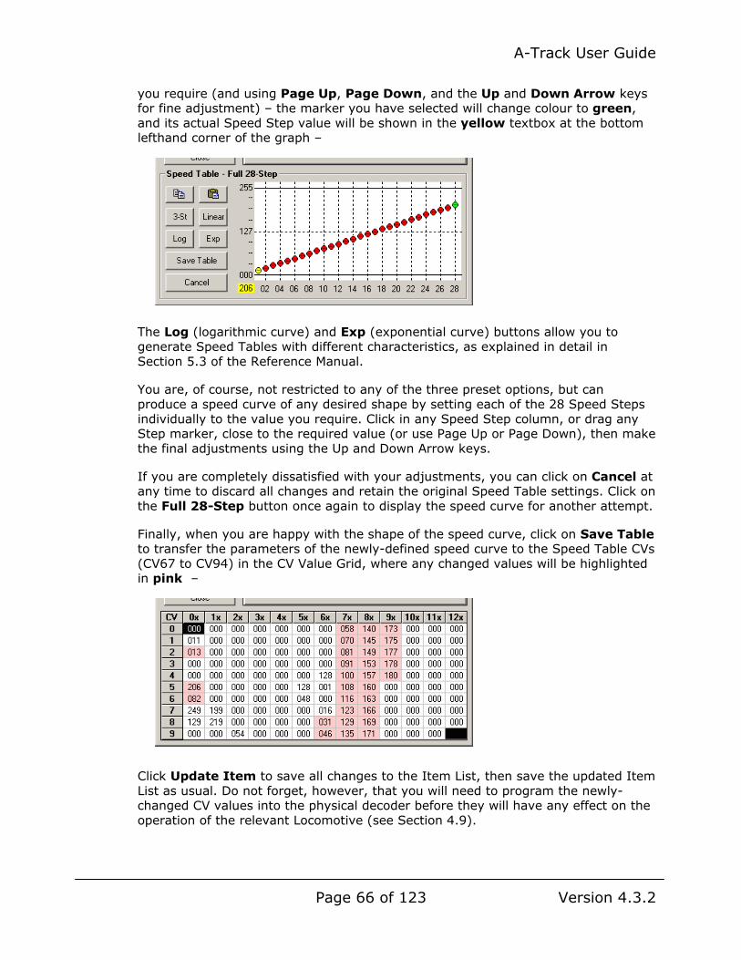
A-Track User Guide
Page 66 of 123 Version 4.3.2
you require (and using Page Up, Page Down, and the Up and Down Arrow keys for fine adjustment) – the marker you have selected will change colour to green, and its actual Speed Step value will be shown in the yellow textbox at the bottom lefthand corner of the graph –
The Log (logarithmic curve) and Exp (exponential curve) buttons allow you to generate Speed Tables with different characteristics, as explained in detail in Section 5.3 of the Reference Manual.
You are, of course, not restricted to any of the three preset options, but can produce a speed curve of any desired shape by setting each of the 28 Speed Steps individually to the value you require. Click in any Speed Step column, or drag any Step marker, close to the required value (or use Page Up or Page Down), then make the final adjustments using the Up and Down Arrow keys.
If you are completely dissatisfied with your adjustments, you can click on Cancel at any time to discard all changes and retain the original Speed Table settings. Click on the Full 28-Step button once again to display the speed curve for another attempt.
Finally, when you are happy with the shape of the speed curve, click on Save Table to transfer the parameters of the newly-defined speed curve to the Speed Table CVs (CV67 to CV94) in the CV Value Grid, where any changed values will be highlighted in pink –
Click Update Item to save all changes to the Item List, then save the updated Item List as usual. Do not forget, however, that you will need to program the newly-changed CV values into the physical decoder before they will have any effect on the operation of the relevant Locomotive (see Section 4.9).

A-Track User Guide
Page 67 of 123 Version 4.3.2
4.3 Functions and Function Mapping
For Locomotive Items, click on the Funct’n Parameter Tab to access the set of Item parameters associated with Functions. This Tab is not enabled for Consists or Accessories.
See Section 5.4 of the Reference Manual for further details.
4.4 Editing CV Values Directly
You can edit any of the CVs in the CV Value Grid, including these NMRA- and manufacturer-specific CVs, by right-clicking on the relevant cell in the CV Value Grid to bring up the Configuration Variable Value page in the Parameter Tabs area of the window as shown in the example below.
This page shows the number of the selected CV with its Description (as also shown on the pop-up label next to the CV location), and its current value listed in decimal, hexadecimal and binary (bits). To change the value of the CV simply click in either of the Dec or Hex textboxes and type in a new value. The value shown in the other (unclicked) textbox is updated automatically to match the entered number –
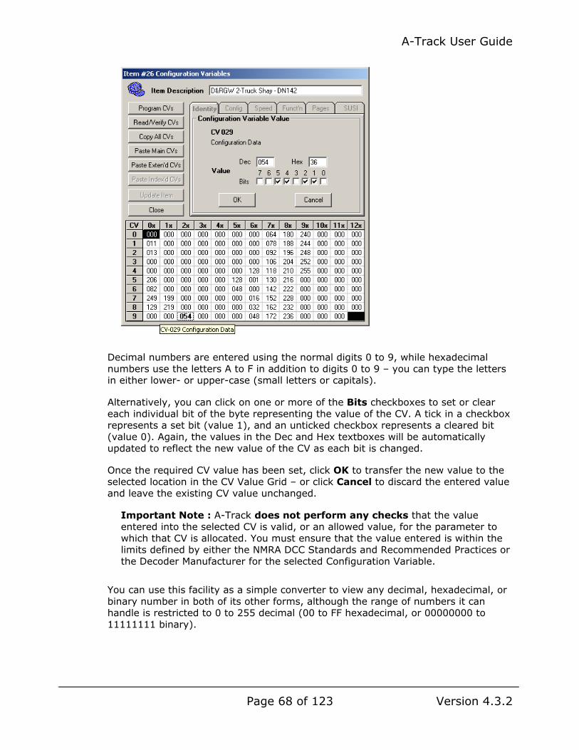
A-Track User Guide
Page 68 of 123 Version 4.3.2
Decimal numbers are entered using the normal digits 0 to 9, while hexadecimal numbers use the letters A to F in addition to digits 0 to 9 – you can type the letters in either lower- or upper-case (small letters or capitals).
Alternatively, you can click on one or more of the Bits checkboxes to set or clear each individual bit of the byte representing the value of the CV. A tick in a checkbox represents a set bit (value 1), and an unticked checkbox represents a cleared bit (value 0). Again, the values in the Dec and Hex textboxes will be automatically updated to reflect the new value of the CV as each bit is changed.
Once the required CV value has been set, click OK to transfer the new value to the selected location in the CV Value Grid – or click Cancel to discard the entered value and leave the existing CV value unchanged.
Important Note : A-Track does not perform any checks that the value entered into the selected CV is valid, or an allowed value, for the parameter to which that CV is allocated. You must ensure that the value entered is within the limits defined by either the NMRA DCC Standards and Recommended Practices or the Decoder Manufacturer for the selected Configuration Variable.
You can use this facility as a simple converter to view any decimal, hexadecimal, or binary number in both of its other forms, although the range of numbers it can handle is restricted to 0 to 255 decimal (00 to FF hexadecimal, or 00000000 to 11111111 binary).

A-Track User Guide
Page 69 of 123 Version 4.3.2
4.5 Accessing Further CV Pages - Sound and Complex Functions
For Locomotive Items, click on the Pages Parameter Tab to access the additional pages of CVs associated with decoders which provide Sound and Complex Function features. This Tab is not enabled for Consists or Accessories.
An additional panel opens, extending the normal Edit CVs window to the right, as shown below. One or more CV Description Tabs will be displayed in the righthand panel, with each Tab containing a list of CVs, arranged alphabetically, relating to the type of DCC Decoder selected in the Decoder Manufacturer section of the Pages Parameter Tab. The Basic CV Description Tab will always be shown, regardless of the decoder type selected, with a list of all of the CVs defined in the NMRA DCC Standards and Recommended Practices.
When first accessing the Pages Parameter Tab, as part of the initial setup of a new Item, as described in Section 2.3, your first action is to select the type of decoder fitted to the Item, since this will determine the number and content of the CV Description Tabs which will be displayed. The simplest case is where the manufacturer of the fitted decoder appears in the list which can be shown by clicking on the Specific Manufacturer option button, and then on the down-arrow ( ) at the righthand end of the listbox below the option button –
In the example above, selecting Digitrax as the decoder manufacturer results in the addition of Config and Sound CV Description Tabs which will contain lists of all those CVs used by Digitrax to control specific features provided in their range of decoders. The Config Tab covers parameters such as lighting effects and the control of momentum and acceleration, while the Sound Tab (obviously) covers the selection of specific sound effects and their relative volumes.

A-Track User Guide
Page 70 of 123 Version 4.3.2
A left click on the name of any CV in a Description Tab will immediately highlight the relevant CV in the CV Value grid, and display its value in the Parameter Tab area, ready for editing if required, as described previously in Section 4.4.
Clicking on ‘Configuration Data’ on the Basic tab, for example, will highlight CV29 and show details of its present value (054) as shown below. To display any another CV Value simply click on its description in the list under the Basic (or any other) Tab, or click Cancel to return to the normal set of Parameter Tabs –
All decoders which provide sound effects, with the exception of those made by MRC, use CVs beyond the NMRA basic range of CV01 to CV128. As defined in the NMRA Standards, the wider range of CVs is divided into pages, each containing 256 CV values, and A-Track further divides each page of CVs into two blocks of 128 CVs each.
Selection of the block to be shown in the CV Value grid is made by clicking the appropriate option button in the View CV Block section of the Pages Tab, with the Lo button showing the lower half of the page, and the Hi button the upper half. Confirmation of which Block is currently on display is indicated by a number in the top left corner of the grid, 000 for the low block of the first CV page, and 128 for the high block, as shown below –

A-Track User Guide
Page 71 of 123 Version 4.3.2
Where the selected Decoder Manufacturer, such as Digitrax or SoundTraxx, does not use any CV greater than CV256, only the Base Page will be enabled in the Access CV Page section, as shown above. However, for decoders which use larger numbers of CVs, the next Extended Page (CV257 to CV512) may also be enabled. A-Track will again display the contents of the Extended Page in two Blocks, the low block (CV257-CV384) indicated by having 256 in the top left corner, and the high block (CV385-CV512) with 384.
Two CV Pages, however, are not sufficient to accommodate the most recent generation of sound decoders from ESU (LokSound), for example, which employ over 600 distinct CVs. In this case, the CVs are accessed using an Indexed Addressing scheme defined by the NMRA. Rather than continue the upward numering of CVs, each additional page of 256 CVs retains the addresses of the Extended page (CV257-CV512) but is identified uniquely by an additional Index value of 1, 2, 3, etc. An Index value of 0 identifies the “real” Extended Page.
The Page Index is set by loading appropriate values to CV31 and CV32, but this is taken care of automatically by A-Track, so that you do not need to be concerned about such details when setting up and programming your locomotive sound decoders.
Full details of how sound decoders using Indexed Pages, from ESU (LokSound) and QSI Solutions (Quantum), are handled can be found in Section 5.6 of the Reference Manual.
4.6 Serial User Standard Interface (SUSI)
SUSI is an interface for adding a slave or secondary decoder to the primary DCC decoder, proposed by the German company Dietz Modellbahntechnik. It is intended to support sound and complex function decoders, and has been provisionally incorporated in the NMRA DCC standards, where it is allocated the use of CV897 to CV1024, inclusive.
However, A-Track does not provide any further operational support for SUSI-equipped decoders, and will not do so until use of SUSI becomes more widespread.
For further details on the SUSI specification see the relevant section of the NMRA DCC standards and the referenced supporting documentation.

A-Track User Guide
Page 72 of 123 Version 4.3.2
4.7 Transferring CV Values Between Items
When initialising the CVs for a new Item added to your roster, it can save a lot of time if you copy the current values from a similar existing Item (and generally with the same make, if not necessarily the same model, of decoder). Then, instead of having to set every single value from scratch, you should only need to alter a small set of key values, including (normally) the Primary and Extended Addresses.
Open an Edit CVs window for the Item which contains the set of CVs you wish to copy, then simply click on Copy All CVs to transfer all CV values to the CV Copy Buffer, a private area of memory within A-Track –
As soon as the copy is complete, the Paste Main CVs and Paste Exten’d CVs buttons will be enabled. If the Item you are copying is set up to use Indexed CV Pages, as is the case in the example above, then the Paste Index’d CVs button will also be enabled.
You can leave this Edit CVs window on the screen if you wish, when proceeding to the next stage, but it is probably safest to Close it now to avoid any mistakes when transferring the copied CVs into another Item.
Next, open the Edit CVs window for the Item which is to receive the copied CVs. This can be either an existing Item or, more usually, a new Blank Item which has just been created. If you have not already done so, carry out the basic initialisation of the Item (by setting its Type – as Locomotive, for example – and entering a Description), then reading in, and safely saving, a copy of the current decoder CV settings (just in case of any unfortunate accidents) as described in Section 2.3.
Now, before you change the recipient Item’s Primary and Extended Addresses, click on Paste Main CVs in the Edit CVs window of that Item –

A-Track User Guide
Page 73 of 123 Version 4.3.2
This action copies the values of CV1 to CV256 from the CV Copy Buffer into CV1 to CV256 of the new Item. The contents of the CV Copy Buffer are retained until replaced by a further Copy All CVs action, so the values can be copied to as many further Items as you wish.
While it is reasonably safe to copy the Main (Base) CV Page into an Item with any type of decoder, the Page still contains a large number of manufacturer-specific CVs as well as the standard NMRA-defined CVs, and you may experience some unusual responses if you copy such values into a decoder from a different manufacturer. It is highly recommended that you restrict copying to between Items which will be fitted with the same make, and preferably model, of decoder.
The same caution applies if you click Paste Exten’d CVs, which will copy the buffered values of CV257 to CV512 into the new Item, together with the Block of CVs specific to SUSI CVs, namely CV897 to CV1024. Having the SUSI CV values loaded into the A-Track Item will not cause any problems with decoders which do not support SUSI, since this range of CVs will only be transferred to a decoder if you select and Program them explicitly (see Section 4.9).
Returning to our example, you will note that, in the new Item, because we have not yet selected the Decoder Manufacturer, the Paste Index’d CVs button is currently disabled, even though the Indexed CV Pages were copied from the original Item.
Click on the Pages Parameter Tab, click on the Specific Manufacturer option button, and select ESU LokSound from the drop-down list as the Decoder Manufacturer (the same as the original source Item). If you now select one of the enabled Index Pages, and then click Paste Index’d CVs, you can see the copied Index Pages being transferred to the new Item –
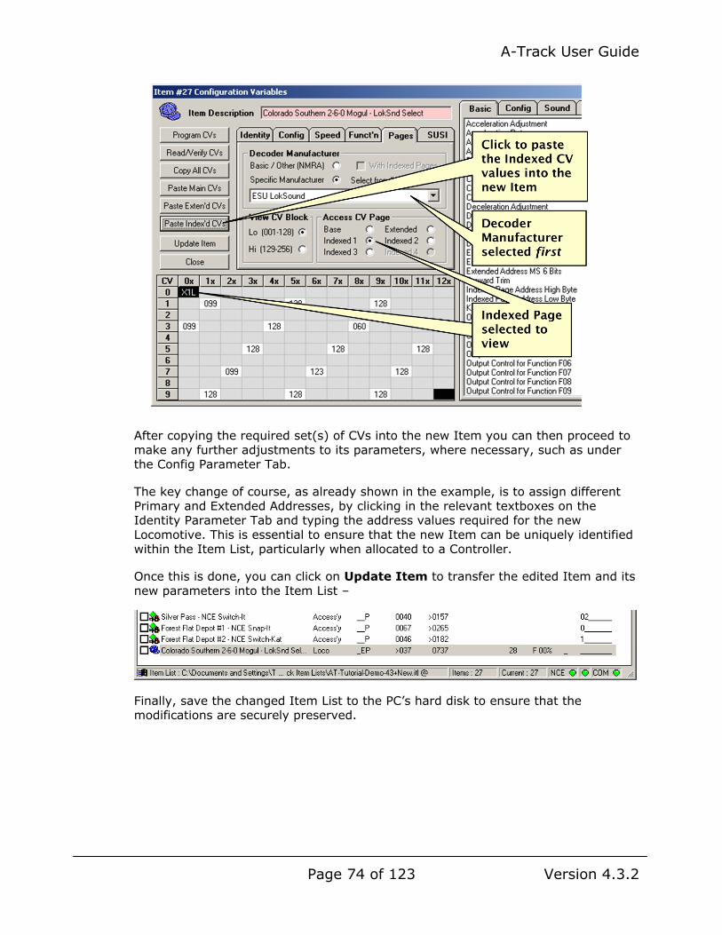
A-Track User Guide
Page 74 of 123 Version 4.3.2
After copying the required set(s) of CVs into the new Item you can then proceed to make any further adjustments to its parameters, where necessary, such as under the Config Parameter Tab.
The key change of course, as already shown in the example, is to assign different Primary and Extended Addresses, by clicking in the relevant textboxes on the Identity Parameter Tab and typing the address values required for the new Locomotive. This is essential to ensure that the new Item can be uniquely identified within the Item List, particularly when allocated to a Controller.
Once this is done, you can click on Update Item to transfer the edited Item and its new parameters into the Item List –
Finally, save the changed Item List to the PC’s hard disk to ensure that the modifications are securely preserved.

A-Track User Guide
Page 75 of 123 Version 4.3.2
4.8 Reading and Verifying CV Values
With the Program Track connected to the appropriate output from the NCE Command Station (Power Cab or Power Pro), placing a physical item (Locomotive) on the Track will allow you to read the current values of all, or of a selected subset, of the locomotive’s DCC decoder Configuration Variables. Only a single locomotive should be present on the Program Track at any one time for correct Read/Verify operations.
This facility is used either to verify that new values programmed into the decoder have been received correctly, or, with a newly-acquired locomotive and/or decoder, to transfer the manufacturer’s factory-set CV values (or the parameters programmed into the decoder using some other equipment, such as an NCE Handheld Cab) from the decoder to the corresponding A-Track Item in the Item List.
The latter operation is one you should always perform with a newly-acquired piece of DCC equipment, so that you know where you are starting from – and have a defined state you can get back to – before altering any of the decoder’s CV values.
Note that, while using A-Track to read and verify a decoder’s CVs, you should not simultaneously attempt to perform a similar operation using an NCE Handheld Cab, or you are likely to confuse the NCE Command Station.
Bear in mind also that, while the Program Track is active, the Mainline Track cannot be used. With the NCE Power Cab, which has only a single power output to connect to both Tracks, a switch to isolate the Mainline Track during Read / Verify and Program operations is recommended, as suggested in the connection diagram in Section 1.1. If you use the Mainline Track for Read/Verify (or Program) operations with an NCE Power Cab, ensure that no other locomotive is present on the track at that time. When using an NCE Power Pro Command Station, power is removed from the Mainline Track when the Program Track is operational.
Now double-click on the Item in the A-Track Item List that is intended to correspond to the locomotive on the Program Track (see Section 2.3). An Edit CVs window opens, displaying the current values of the Item’s first 128 CVs in the CV Value Grid occupying the lower half of the window.
Before proceeding further, you need to refine the overall group of CVs to be accessed by the Read/Verify operation. The CV Range options allow you to select either only the Current View, ie. the block of 128 CVs presently shown in the CV Value grid, or All CV Blocks, ie. the full complement of all CV Pages defined in the Item (with the exception of the SUSI block). Note that if you want to access a specific block of CVs other than that currently on view, then you will have to display that block from the Pages Parameter Tab before clicking the Read/Verify CVs Action Button – an example will be shown later.
Within the selected CV Range, you can then choose a CV Scope, by clicking on the appropriate option button, of either All CVs or only those which are Selected, ie. are highlighted.
To select a subset of the CVs currently displayed in the CV Value Grid of the Edit CVs window, click on the first CV to be selected, hold down either Shift ( ) key, then click on the last CV in the group. The group of CVs, from the first to the last selected, will be highlighted with a yellow background. Note that selection is done
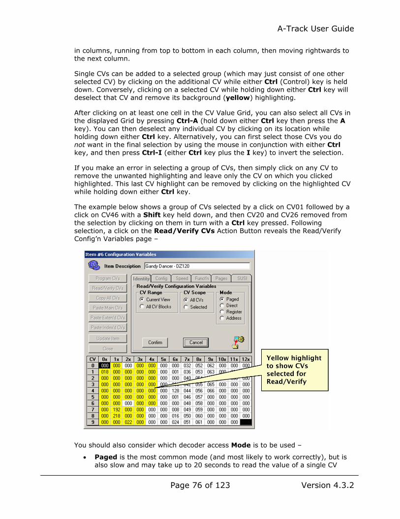
A-Track User Guide
Page 76 of 123 Version 4.3.2
in columns, running from top to bottom in each column, then moving rightwards to the next column.
Single CVs can be added to a selected group (which may just consist of one other selected CV) by clicking on the additional CV while either Ctrl (Control) key is held down. Conversely, clicking on a selected CV while holding down either Ctrl key will deselect that CV and remove its background (yellow) highlighting.
After clicking on at least one cell in the CV Value Grid, you can also select all CVs in the displayed Grid by pressing Ctrl-A (hold down either Ctrl key then press the A key). You can then deselect any individual CV by clicking on its location while holding down either Ctrl key. Alternatively, you can first select those CVs you do not want in the final selection by using the mouse in conjunction with either Ctrl key, and then press Ctrl-I (either Ctrl key plus the I key) to invert the selection.
If you make an error in selecting a group of CVs, then simply click on any CV to remove the unwanted highlighting and leave only the CV on which you clicked highlighted. This last CV highlight can be removed by clicking on the highlighted CV while holding down either Ctrl key.
The example below shows a group of CVs selected by a click on CV01 followed by a click on CV46 with a Shift key held down, and then CV20 and CV26 removed from the selection by clicking on them in turn with a Ctrl key pressed. Following selection, a click on the Read/Verify CVs Action Button reveals the Read/Verify Config’n Variables page –
You should also consider which decoder access Mode is to be used –
• Paged is the most common mode (and most likely to work correctly), but is also slow and may take up to 20 seconds to read the value of a single CV

A-Track User Guide
Page 77 of 123 Version 4.3.2
(Note that the NMRA term ‘Paged’ used here is completely unrelated to the CV Pages defined for the NMRA Indexed Addressing scheme)
• Direct is much faster, but is not supported by all decoders
• Register is similar to Paged, but only reads a very small subset of seven CVs, consisting of CV1 to CV4, CV7, CV8, and CV29
• Address is a legacy mode which only allows you to read the value of CV1
Click to select the required Mode, or leave it at the default setting of Paged.
For a first example of the Read/Verify operation, assume that no CVs are selected, CVRange and CV Scope are left at the default settings, and that Register Mode has been selected, then click Confirm to start the Read/Verify operation.
During the Read/Verify operation, the CV currently being accessed will be highlighted in red. Once the CV value held in the decoder has been determined, it will be displayed in the grid and highlighted in light green if the value read is the same as that held in the Item, or highlighted in pink if it differs from the Item’s stored value.
A typical display for a Register Mode Read/Verify operation in progress is shown below. Note the animated ‘egg timer’ icon being shown to indicate a currently active operation, and that all buttons other than Cancel are ‘greyed-out’ to prevent any interference with the Read/Verify process. Clicking Cancel will stop the Read/Verify operation eventually – in Paged or Register Modes this can take up to 20 seconds (regardless of how many times you click the Cancel button) – but the value read from the currently accessed CV cannot then be relied upon to be correct.

A-Track User Guide
Page 78 of 123 Version 4.3.2
Once the Read/Verify operation has been completed, a message is displayed to indicate the result -
Click Finish to complete the Read/Verify operation. All highlighting of CVs will be removed except for those CVs where the value read from the decoder differs from that currently held in the Item. Such CVs will retain their pink highlight. Any CVs which were highlighted (yellow) before starting Read/Verify, but not accessed during the operation, will also retain their highlight.
If the Read/Verify operation fails for any reason then the value of the CV which could not be determined is set at zero, and indicated as a failure by ‘striking-through’ the digits (000).
Failure to complete the requested Read/Verify operation can be due to several causes –
• The Program Track is not properly connected to the NCE Command Station
• The locomotive is not in good contact with the Program Track, or the decoder wiring/connection is defective
• The decoder does not support the selected access Mode (particularly Direct)
• A sound decoder is fitted and is overloading the Program Track drive capability of a standard NCE Power Pro Command Station – a programming booster unit (such as the SoundTraxx PTB-100 or DCC Specialities PowerPax) requires to be inserted between the Command Station and the Program Track – such a unit is not generally required when using an NCE Power Cab
• The decoder does not support the use of specific CVs and does not respond to Read/Verify commands when these CVs are accessed. This is a ‘feature’ of QSI Quantum sound decoders, for example, and, once you know which CVs are

A-Track User Guide
Page 79 of 123 Version 4.3.2
unsupported, you can omit these CVs from your selection in order to speed up the overall Read/Verify operation.
The Read/Verify operation continues with the next CV following any failure.
However, when an unexpected failure does occur (or for any other reason) you can stop the operation by clicking the Cancel button although, as noted previously, this can take up to 20 seconds in Paged or Register Modes (regardless of how many times you click the Cancel button).
In the example shown below, with a selected range of CV15 to CV35, Read/Verify has failed to read the values of CV27 and CV28, and has been halted by the user in the course of reading CV32 (for which the value shown may be incorrect), leaving the remainder of the selection (CV33-CV35) unread –
You can carry on with the Read/Verify operation from the next selected CV by clicking on Continue, when the Read/Verify operation will restart at CV33, continuing up to CV35. Click Finish to terminate the Read/Verify operation.
Following a failure of the Read/Verify operation, and after checking all of the Program Track electrical connections, and the contact between the locomotive and the track – in case the failure was due to some temporary condition – you can repeat the operation.
Either individually select each of the CVs where Read/Verify failed, and is indicated by ‘strikethrough’, or select any one and then press Ctrl-L (hold down either Ctrl (Control) key then press the L key), which will select all CVs marked by ‘strikethrough’, and then retry the Read/Verify operation with the CV Scope set at the Selected option.

A-Track User Guide
Page 80 of 123 Version 4.3.2
Where a sound, or other, decoder uses CVs beyond the Base Lo Block that is normally displayed in the Edit CVs CV Value grid, you can select a CV Range of All CV Blocks for Read/Verify. Irrespective of the selected CV Scope (All CVs or Selected) A-Track will then proceed to step progressively through every (selected) CV value in each CV Block allocated to the Item.
Note, however, that this extensive Read/Verify operation will take an appreciable amount of time. In the case of ESU LokSound decoders, for example, the full operation will take around 20 to 30 minutes to complete when using Direct Mode, where each CV read requires 1 to 2 seconds. If you choose to use Paged Mode instead, the operation will potentially occupy several hours.
Although Read/Verify of QSI Quantum decoders takes up to 4 seconds per CV Value, because of the overhead of setting the Primary and Secondary Indexes before reading each value, the overall time to access all CV Pages in Direct Mode will only be around 35 minutes, because of the lesser number of CVs to access. Again, in Paged Mode, the operation will need several hours to complete.
Unfortunately, the NCE Power Pro Command Station (and its Serial Interface, in particular) was never designed to be used continuously for such extended periods, and it is highly likely that it will lock up at some stage, even when used in conjunction with a programming booster unit. This is usually indicated by a sequence of failed CV reads followed by one or both of the left- and rightmost Status Bar indicators changing to yellow.
In such cases, cancel the Read/Verify operation, then switch off the NCE Power Pro Command Station. Allow around 20 seconds for the Command Station to power down fully, then switch it back on – when A-Track should re-establish the connection. Only in exceptional circumstances should it be necessary to restart the A-Track program itself.
The NCE Power Cab is much more robust in this respect, and can usually be relied upon to complete even the most extended Read/Verify operation.
However, the recommended way of using A-Track for Read/Verify operations (and for Program operations, as described in the following Section 4.9) is to handle a single CV Block at a time.
Hence, before starting the Read/Verify operation, click on the Pages Parameter Tab, and select the Block of interest using the Access CV Page and View CV Block options –

A-Track User Guide
Page 81 of 123 Version 4.3.2
Ensure the locomotive is on the Program Track, then click the Read/Verify CVs Action Button and wait for the operation to complete.
When all available or selected CVs have been read, exit the final Read/Verify operation by clicking Finish, then click Update Item to save the values retrieved from the decoder to the Item in the Item List. Finally, save the complete (changed) Item List to secure the information.
This back-up philosophy ensures that you have an accurate record of the contents of the Item’s decoder stored within the A-Track Item List, and should be regarded as an essential operation to record the original state of a newly-acquired locomotive decoder before you begin to make any changes or ‘improvements’.
As explained previously, do this by first creating a new Locomotive Item (see Section 2.3) and giving it a suitable Description. Leave the assigned Addresses at their default values, click the Pages Parameter Tab to select the appropriate Decoder Manufacturer and set the correct number of Extended and Indexed CV Pages.
After clicking the Read/Verify CVs Action Button, if you are using an NCE Power Cab it is probably safe to select All CV Blocks and All CVs, and leave A-Track to proceed. However, with an NCE Power Pro system, the safer strategy is to follow the recommendation of selecting and operating on only the single Block in view at a time.
Select Direct Mode to give the fastest Read/Verify operation, if you know that the new decoder supports it, otherwise leave the Mode at Paged, then click Confirm and proceed as described in the previous paragraphs.

A-Track User Guide
Page 82 of 123 Version 4.3.2
4.9 Programming CV Values
Having set up, or changed, the required values of all or some of the CVs for an Item (such as the Primary or Extended Address), the next step, after saving a copy back to the Item List, is to transfer the new CV values to the actual DCC decoder. This can be done either on the Program Track (Service Mode programming) or on the Mainline Track (Operations Mode programming).
Operations Mode programming is useful to ‘fine-tune’ selected decoder parameters when a locomotive, for example, is running on the Mainline, having set up the majority of CV values for the decoder on the Program Track. However, unless you are using a sound decoder with verbal read-out of CV values, you cannot use Operations Mode to read back the programmed value and confirm that it has been set correctly.
Note that not all decoders (especially older models) support Operations Mode programming commands.
Be aware, also, that some decoders which do support Operations Mode programming will still not allow you to change Address values via Operations Mode (since the current decoder Address has to be included in the command to update a decoder CV value on the Mainline). In such cases, Address changes will have to be programmed on the Program Track.
After opening up an Edit CVs window for the Item corresponding to the decoder to be programmed, the method of selecting which CVs to Program is the same as that used for the Read/Verify operation in Section 4.8 above, and the same decoder access Modes are available.
As before, the recommended way of using A-Track for Program operations is to handle a single CV Block at a time, particularly when using an NCE Power Pro Command Station. Hence, particularly when accessing a decoder with Extended or Indexed CV Pages, before starting the Program operation, click on the Pages Parameter Tab, and select the Block of interest using the Access CV Page and View CV Block options.
With the locomotive to be programmed located on the appropriate Track (and the only locomotive present if using the Program Track and Service Mode), click on the Program CVs Action Button to show the Program options page.
In addition to options to program All or Selected CVs, you can also choose to program only those CVs whose value has been Changed, ie. those currently highlighted in pink. Note that whenever a changed CV is selected, its highlight will become orange (rather than pink or yellow).
Click Confirm to start the Program operation.
In the example below, programming of the decoder is set to be on the Program Track, in Paged Mode, of the Selected CVs from CV01 up to CV29 (yellow). CV05 and CV06 are currently shown as changed as well as being selected (orange). CV01 through CV03 have already been programmed successfully, so are now shown with a light green background, while CV04, which is currently being programmed into the decoder, is highlighted in red –

A-Track User Guide
Page 83 of 123 Version 4.3.2
When programming of all selected CVs is completed, they should all be highlighted in light green –

A-Track User Guide
Page 84 of 123 Version 4.3.2
Note, however, that this, even together with the displayed message "Programming Completed Successfully", does not necessarily signify that the Program operation transferred the correct value to each of the highlighted CVs.
Acknowledgements that the decoder has accepted the value being programmed are only generated on the Program Track (when using Service Mode programming), but even here it is allowable, under NMRA Recommended Practices, for the Command Station to proceed to program the next CV regardless of whether any acknowledgement was received from the decoder.
No acknowledgements are generated by the decoder when it is sent Operations Mode programming commands on the Mainline Track (although some decoders will still power the locomotive motor on for a brief period to show that a programming command was received).
The only reliable way to check that the decoder programming has been successful is to perform a subsequent Read/Verify operation on the Program Track.
Once the Program operation has completed fully, click Finish to close the process and return to display the previous Parameter Tab.
Programming on the Mainline Track is performed in exactly the same way as on the Program Track but, before clicking the Confirm button to start the operation, click the checkbox labelled Program on Main Track to place a tick in it. This will disable the Program Track access Modes.
The example below shows the Operations Mode programming of the decoder’s Speed Table (CV67 to CV94) which has just been set up under the Speed Parameter Tab, so that the CVs are highlighted in pink, but which has then had the programming operation interrupted –

A-Track User Guide
Page 85 of 123 Version 4.3.2
As with Read/Verify, clicking Cancel at any time will stop the Program operation as soon as possible, displaying the appropriate status message, as shown in the result above.
From this point you can resume the Program operation from the next selected CV by clicking Continue, but note that the state of the decoder CV at which you stopped, in this case CV84, is indeterminate – it may or may not have been programmed with the Item CV value – so you may have check it later via Read/Verify, then use another Program operation to set its value correctly, if required. Alternatively, you can terminate all programming by clicking on Finish.
Although the Program operation itself does not change any of the Item’s CV data stored in the Item List, it does clear the Not Programmed (P) flag in the copy of the Item’s parameters held within the Edit CVs window, as soon as you click on the Finish button, to indicate that the Item CVs have been transferred to a decoder and, if you click Close rather than Update Item, you will be prompted to save the changed Item parameters to the Item List.
However, if any CV values were changed immediately prior to programming, and have not yet been transferred to the Item, you should definitely click Update Item at the end of the Program process to transfer the updated values to the Item entry in the Item List.
4.10 Defining and Assigning Locomotives to Consists
A Consist is a defined group of locomotives which are controlled as a single entity using a single unique address given to the Consist. Technically, as far as the NMRA DCC Standards & Recommended Practices are concerned, this is known as an Advanced Consist, and is the only form of Consist which is handled by A-Track.
Consists can be defined independently by either type of NCE System, using the commands available through the NCE Handheld Cabs, and by the A-Track program. A-Track allows the definitions of Consists to be transferred to and from an NCE Power Pro System so that, by letting you see the exact composition of each Consist, you will be able to resolve any conflicting Consist definitions which might exist between the two systems. As described in Section 2.1, A-Track loads the addresses of all defined Consists from an NCE Power Pro System as soon as it is connected to the Command Station. This facility is not available when operating with an NCE Power Cab (or Smart Booster) System.
Note, however, that as far as control of a specific Consist is concerned, the definition of its constituent locomotives currently held in either type of NCE Command Station takes precedence over any Consist with the same address currently defined in the A-Track Item List.
From an A-Track point of view, a Consist is essentially just another Item, but one which has a very restricted set of parameters, made up of a Description, a Type, an Address, and a list of Locomotives which have been designated as belonging to this Consist. Although a Consist does use some Configuration Variables for its own internal storage, you cannot edit any of these CVs directly.

A-Track User Guide
Page 86 of 123 Version 4.3.2
When a Locomotive Item is assigned to a Consist, that Loco’s Address is added to the Consist’s assignment list, the Type of the assigned Item is changed from Locomotive to Multiple, and the Consist Address is stored in CV19 of the Locomotive (now Multiple) Item. You can continue to edit, read/verify, and program the remaining CVs of a Multiple Item in exactly the same way as you can those of an independent Locomotive Item.
See Sections 5.11, 5.12, and 5.13 of the Reference Manual for further details of defining, activating, and controlling Consists.
4.11 Accessories – Operation and Parameters
As introduced in Section 4.1, Items in A-Track can also hold the parameters of decoders designed to operate model railroad layout accessories such as turnout and signal controllers. At present, there are not many signal controllers on the market, so support in A-Track is currently directed towards DCC decoders intended to drive a variety of turnout motors. Although A-Track will handle accessory decoders from a range of suppliers, including Digitrax and Lenz, specific features are implemented to support the range of accessory decoders produced by NCE Corporation.
For an Accessory Item held in an A-Track Item List, the format of the Identity Parameter Tab contains the same information as any other Item, as shown below. A new Blank Item is initialised as an Accessory by clicking on the Accessory option under Item Type, and then entering a suitable Description, possibly describing the function or location of the Accessory on the layout, followed by a Decoder Address, in the appropriate textboxes –

A-Track User Guide
Page 87 of 123 Version 4.3.2
In the original definition for the format of Accessory Decoder parameters in the NMRA DCC Standards and Recommended Practices, valid Accessory Decoder Addresses range from 1 to 511. Each Accessory Decoder is assumed to have four pairs of Outputs which can be switched ‘On’ or ‘Off’, ie. when one output of an output pair is ‘On’, the other is ‘Off’, and vice versa.
Each Output pair is assigned an address, based on the allocated Decoder Address, which you can use to send a command, from a Handheld Controller, for example, to change the state of that Output pair. As can be seen in the Outputs 1 – 4 Address + Time On area in the view of the Config Parameter Tab shown in the example below, the address of Output #4 (1040) is calculated by multiplying the Decoder Address (0260) by 4, and then subtracting 1, 2, or 3 from this value to obtain the addresses of Outputs #3, #2. and #1, respectively –
As can be seen above, each Output Address value has an associated textbox (to its right) where you can set the period for which either output of each pair will stay in the ‘On’ state following receipt of an activating command. The value to be entered into a Time On textbox for a given output duration is set by the decoder manufacturer (commonly as units of 0.1 second).
In addition, you can select which of the decoder’s Auxiliary Inputs, connected to external pushbuttons, for example, will operate the corresponding Accessory Output when activated, by clicking to tick the appropriate checkbox in the Auxiliary Input Activation area.
Although the NMRA DCC Standards and Recommended Practices generally assume that accessory decoders (like those for locomotives) will have their Address, at least, programmed on a separate Program Track, this is not always practical where a particular decoder is likely to be wired directly (and permanently) to both the

A-Track User Guide
Page 88 of 123 Version 4.3.2
Mainline Track and to the turnout motors or other accessories which it is intended to control, and to be located near to the accessories rather than to a Program Track.
Hence, original-style accessory decoders such as the Wangrow SM-104 shown in the example above, or the similar Digitrax DS54, are now regarded as obsolete, and most manufacturers now produce accessory decoders which are designed to have their Addresses, and any other parameters, programmed directly from the Mainline Track in conjunction with switch settings on, or special temporary wired connections to, the decoder itself.
Also, instead of having a fixed set of four output pairs, linked to a common Address, a range of accessory decoder types are now produced by several manufacturers with between 1 and 8 output pairs, together with the facility to allocate separate, independent Addresses to each output pair.
Hence, when you set up an Item to represent one of these modern accessory decoders, you should click to tick the checkbox labelled Manuf Specific (Program on Main Track) in the Programming area. This will automatically set Output Addressing mode, and then disable the checkbox so that the mode cannot be deselected by accident.
When the Manuf Specific checkbox is ticked, a third Parameter Tab labelled Addrs will be displayed , and will allow you to allocate up to eight addresses to the Accessory Item, together with several other options, as shown below for a new Item in the process of being set up –
Note that the Decoder Address for this new Item has been set to the default value of 0001 and that, for consistency with the NMRA DCC Recommended Practices, the set of Output Addresses directly associated with that Address (0001 to 0004), are

A-Track User Guide
Page 89 of 123 Version 4.3.2
shown by A-Track on the Config Parameter Tab, as above. Note, however, that these Addresses will not necessarily correspond to the actual Output Addresses finally allocated to the decoder using the programming mechanisms defined by the decoder manufacturer.
Clicking on the Addrs Parameter Tab allows you to enter addresses for up to eight individual decoder output pairs. When setting up a new Item, as in this case, your first action should be to select the number of output pairs provided by the particular decoder associated with this Item, by clicking on the down-arrow ( ) at the end of the Number of Outputs listbox and then clicking on the appropriate number in the drop-down list (4 for a Digitrax DS44 Accessory decoder) –
This action will enable the corresponding number of Output Address textboxes, and will fill them with sequential Output Address values calculated from the current Decoder Address (0001 here) as entered on the Identity Parameter Tab –
You can now enter the set of Output Addresses that you want for the Item into the enabled textboxes, in accordance with any rules or limitations set out by the

A-Track User Guide
Page 90 of 123 Version 4.3.2
manufacturer of the target decoder ie. as a group of sequential values, or as several independent addresses.
Valid Output Addresses must lie between 0001 and 2044, so that, if you enter a value outside this range, an error message will be displayed –
- and the entered value will be reset to 0001.
If you wish to set all of the enabled Output Addresses to a set of sequential values without entering each address individually, then you should click to tick the Sequential Addresses checkbox. Now enter any one of the required address values into the appropriate Output textbox and press the Enter/Return key. All of the other enabled Output textboxes will then be filled with the required addresses, as shown in the example below. If any of the address values would exceed 2044, then an error message similar to that above will be displayed, and the complete set of sequential addresses will be adjusted to bring them all within the allowed range.
Note that, if you have already entered one of the required sequential addresses without having ticked the Sequential Addresses checkbox, simply click on the checkbox to tick it now, then click on the entered address to highlight it, followed by a press of the Enter/Return key –
Although most manufacturers of accessory decoders do not make any reference to CV values as far as addresses are concerned, A-Track will display the currently selected Output Address as the Accessory Address on the Identity Parameter Tab, and will use its value to update the Decoder Address in CV01 (to 023 here), together with the related group of “Output Addresses” on the Config Parameter Tab, as shown below, in order to maintain consistency, as far as possible, with the NMRA DCC Recommended Practices. Note that these updates within the Item have

A-Track User Guide
Page 91 of 123 Version 4.3.2
no effect on the way the real accessory decoder is handled by A-Track, using the specific programming and operating mechanisms defined by the particular decoder manufacturer (see the following Section 4.12 on programming accessory decoders).
Returning to the initial setup of a new Accessory Item, if the target decoder is an accessory decoder manufactured by NCE Corporation, then, as well as ticking the Manuf Specific checkbox in the Programming area, you should also tick the (now enabled) NCE Decoder checkbox. As before, this action will enable display of the Addrs Parameter Tab but, when you click on the Addrs Tab and select the Number of Outputs as 1 from the drop-down list, only three of the eight Output Address textboxes will be shown, together with two enabled sets of additional options –

A-Track User Guide
Page 92 of 123 Version 4.3.2
The NCE Timing parameters apply only to NCE Snap-It or Switch-Kat accessory decoders, which have only a single Output Address. Hence, if you set the Number of Outputs to any value other than 1, the NCE Timing area will be removed, with the Output Address – Sel area expanding to show all eight Output Address textboxes again.
The number (and type) of options available in the NCE Options area depends on the type of NCE accessory decoder which is, in turn, set by the number of outputs selected. A-Track assumes that if a single output is selected then the decoder is either an NCE Snap-It or Switch-Kat, if two outputs then it is an NCE Switch-It, and if eight outputs then it is an NCE Switch-8, as shown in the examples below. If any other number of outputs is selected, then A-Track assumes that the NCE Decoder checkbox was ticked in error, and the NCE Options are disabled.
Note that some of the NCE Options apply to individual outputs (such as Rev Output Polarity for an NCE Switch-8), whereas others apply to the whole decoder (such as No Legacy Ops Prog for an NCE Switch-It), and, hence, remain in force whichever

A-Track User Guide
Page 93 of 123 Version 4.3.2
Output Address is selected as active. You should refer to the relevant NCE technical documentation for each decoder type for full details of how each applicable option affects operation of the decoder.
Unlike other manufacturers, NCE Corporation makes use of Configuration Variables, in the range of CV545 to CV556 (shown in the CV Grid as CV33 to CV44), to hold the operating parameters of their range of accessory decoders. CV515 (CV03) is also used to hold the Output On-Time for the Switch-Kat single-output decoder.
Note, however, that it is not possible to read back any of the set values of these CVs by connecting the decoder to the Program Track and using Read/Verify. The NCE accessory decoder CVs can only be programmed using Operations Mode (Program on Main Track) when connected to the Mainline Track, as covered in the following Sections 4.12 and 4.13.
When the setup of your new Accessory is completed, you should, as usual, click Update Item to save the Accessory back to the Item List. If you click Close, you will be prompted to either save or discard the edited Item before the Edit CVs window is closed.
The display of an Accessory’s key parameters in the Item List is a little different to those of Locomotive Items, as shown in the example below –
The Decoder Address of the Accessory is shown in the Primary Address column, with the currently selected Output Address shown in the Extended Address column. Accessories using Manufacturer Specific programming are identified by placing a ‘>’ symbol in front of the Output Address, whereas older style decoders using NMRA standard addressing will have the ‘>’ symbol preceding the Decoder Address.
The rightmost Function 1-8 column is used to show the state of each Accessory Output which resulted from the last issued command. If you are using an NCE Power Pro Command Station, then this Output data is obtained from the Command Station, so reflects commands sent from both A-Track and Handheld Cabs. However, such data is not available from an NCE Power Cab system, so the column only shows data sent from A-Track and saved within the Accessory Items in the Item List. See the Section 3.9 on Accessory control for further details regarding the monitoring of Output states, and Section 5.14 of the Reference Manual for further information on the set up of Accessory decoders.

A-Track User Guide
Page 94 of 123 Version 4.3.2
4.12 Programming Accessory Decoders – Edit CVs Window
All available modern accessory decoders which are designed to operate turnouts can have the address of each of their outputs programmed remotely via the Mainline Track. The usual method of doing this is to send an ‘Operate Turnout’ command from the Command Station to the required output address, while the accessory decoder is configured in programming mode.
The configuration method required to do this is specific to each manufacturer, where techniques include the use of switches mounted on the decoder, temporarily-fitted wire links or push-on jumpers, or additional temporary connections from the decoder to the Mainline Track while programming takes place.
Addresses selected for Accessory Items defined in an A-Track Item List, together with some additional parameters, can be programmed into the corresponding decoder, once the decoder is connected to the Mainline Track, in either of two ways, one via the Edit CVs window, as covered in the rest of this section, and the other by issuing Accessory operating commands, which is described in Section 4.13.
For the first method, double-click on the Item to open the Edit CVs window, then click on the Addrs Parameter Tab. Select the Output Address to be programmed by clicking on the relevant Sel option button (Output 3 in the example below), then click the Program Accessory button –
A prompt will appear, reminding you to configure the relevant accessory decoder (connected to the Mainline Track) ready for programming –

A-Track User Guide
Page 95 of 123 Version 4.3.2
When the decoder is correctly set up, click OK to proceed, and to display the Program CVs page with all of the necessary options pre-selected. The Decoder Address CVs are highlighted in yellow, to indicate programming of an address, although the actual value programmed will be that of the selected Output Address –
In this case, for a Digitrax DS44, the decoder’s White wire is temporarily connected to one of the Mainline Track rails to enable programming of the Output Address(es). For this, or any other type of accessory decoder, refer to the supplied manufacturer’s documentation for full details of the required configuration.
Click Confirm to issue an ‘Operate Turnout’ command using the selected address. The operation will be confirmed visually by the normal Programming sequence described in Section 4.9 where CV01 is first highlighted in red, and should end with both CV01 and CV09 highlighted in light green, together with display of a confirmation message –
Click Finish to return to display of the Addrs Parameter Tab.

A-Track User Guide
Page 96 of 123 Version 4.3.2
Where the Accessory Item represents an NCE decoder, as shown in the example on the left, additional decoder parameters can be programmed via the Mainline Track using Operations Mode.
In this example, Output Address 1 (0156) has been selected for programming, together with the required state of the available options in the NCE Options section of the Addrs Tab.
Here, the relevant Configuration Variables have been updated to reflect the selections, so are highlighted in pink, although this would not be the case if no changes had been made in the Edit CVs window after it had been opened.
Programming of the additional NCE decoder parameters should, of course, only be done after programming the NCE decoder Output Address, as described in the previous paragraphs, but is then initiated, as before, by clicking on the Program Accessory button to open the Program CVs page –
Clicking on the NCE Options button in the Access’y Scope area will then highlight the parameter values in the CV Grid in yellow (or orange, in this case, since the CVs were already marked as ‘changed’ with a pink highlight).
If you do not want to program all of the NCE Options at this time, you can remove the yellow or orange highlight from those you want to leave as they are, by holding down either Ctrl (Control) key on your keyboard and then clicking on the relevant cell in the CV Grid.

A-Track User Guide
Page 97 of 123 Version 4.3.2
If you make a mistake, you can restore the highlight by simply clicking on the CV cell again while continuing to hold down a Ctrl key. To assist selection of the correct CV, descriptions of each CV will pop up when you hover the mouse cursor over each cell in the CV Grid –
When you are satisfied, click Confirm to proceed, where progress will be indicated with the normal red and light green highlighting –
Completion of programming is signalled by the normal ‘success’ message –
Click the Finish button to return to the Addrs Parameter Tab.

A-Track User Guide
Page 98 of 123 Version 4.3.2
Note that when programming an Accessory’s address or parameters there is no feedback from the Mainline Track to positively confirm whether the operation has been successful or not. The only way to verify the outcome is to operate the Accessory using a Handheld Cab, or via the A-Track Operate facility described in Section 3.9.
If you use NCE Snap-It or Switch-Kat acccessory decoders, there are some additional timing parameters which can be programmed. These NCE Timing parameters are displayed next to the other NCE Options on the Addrs Parameter Tab, where you can enter the value or values you require in the relevant textbox (having checked the decoder documentation for the allowable range of values) –
After you click Program Accessory, and have answered OK to the normal request to configure the decoder for programming, when you click on the NCE Options button on the Program CVs page, a further message will be displayed –
Clicking Yes will select the relevant NCE Timing CVs in the CV Grid in addition to the other NCE Options CVs by highlighting them in yellow (or orange), whereas clicking No will leave the selection at the NCE Options only –
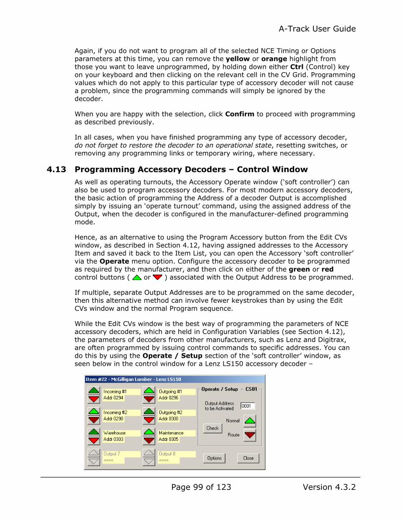
A-Track User Guide
Page 99 of 123 Version 4.3.2
Again, if you do not want to program all of the selected NCE Timing or Options parameters at this time, you can remove the yellow or orange highlight from those you want to leave unprogrammed, by holding down either Ctrl (Control) key on your keyboard and then clicking on the relevant cell in the CV Grid. Programming values which do not apply to this particular type of accessory decoder will not cause a problem, since the programming commands will simply be ignored by the decoder.
When you are happy with the selection, click Confirm to proceed with programming as described previously.
In all cases, when you have finished programming any type of accessory decoder, do not forget to restore the decoder to an operational state, resetting switches, or removing any programming links or temporary wiring, where necessary.
4.13 Programming Accessory Decoders – Control Window
As well as operating turnouts, the Accessory Operate window (‘soft controller’) can also be used to program accessory decoders. For most modern accessory decoders, the basic action of programming the Address of a decoder Output is accomplished simply by issuing an ‘operate turnout’ command, using the assigned address of the Output, when the decoder is configured in the manufacturer-defined programming mode.
Hence, as an alternative to using the Program Accessory button from the Edit CVs window, as described in Section 4.12, having assigned addresses to the Accessory Item and saved it back to the Item List, you can open the Accessory ‘soft controller’ via the Operate menu option. Configure the accessory decoder to be programmed as required by the manufacturer, and then click on either of the green or red control buttons ( or ) associated with the Output Address to be programmed.
If multiple, separate Output Addresses are to be programmed on the same decoder, then this alternative method can involve fewer keystrokes than by using the Edit CVs window and the normal Program sequence.
While the Edit CVs window is the best way of programming the parameters of NCE accessory decoders, which are held in Configuration Variables (see Section 4.12), the parameters of decoders from other manufacturers, such as Lenz and Digitrax, are often programmed by issuing control commands to specific addresses. You can do this by using the Operate / Setup section of the ‘soft controller’ window, as seen below in the control window for a Lenz LS150 accessory decoder –

A-Track User Guide
Page 100 of 123 Version 4.3.2
Using the LS150 decoder’s pushbutton and indicator LED to set the decoder into programming mode, following the manufacturer’s instructions, the address of each of the six Outputs is programmed into the decoder, in sequence, by clicking either of the green or red control buttons ( or ) appropriate to that address. Following the transfer of each address, the next step in the decoder’s programming sequence is to set the ‘On’ duration of each Output.
The method of doing this is to send a control command to an Accessory address, the value of which represents the required duration. Acceptable values are in the range of 1 to 100, with each unit equating to 0.1 second. So, if we require the Output to be ‘On’ for 4 seconds when activated, we send a turnout command to Accessory address 0040 by typing this address into the Output Address textbox in the Operate / Setup area, as shown below, and then clicking either the Normal or the Route control button below the textbox –
The process is repeated as necessary to set the decoder parameters to the required values. Note that, if we actually have a turnout with address 0040 on the layout, then it will also respond to the set parameter command by moving in the appropriate direction, although this will not affect the transfer of the duration value to the LS150 decoder.
In addition to issuing programming or setup commands to the decoder directly associated with the Accessory Item ‘soft controller’, the controls of the Operate / Setup area can be used to program the address of any other suitable decoder on your layout. Simply enter the required address into the Output Address textbox, configure the target decoder for programming in accordance with the manufacturer’s instructions, and click either the Normal or Route control button to program that address into the decoder.
You can also check the last-commanded state of any turnout on your layout by entering its address to the Output Address textbox, and then clicking the Check button.
Either the Normal or the Route button will then be displayed in its ‘bright’ state ( or ) to show the current turnout status, with the other button in its ‘dark’ state ( or ). Clicking Check does not issue any turnout command, nor alter the recorded turnout status in either A-Track or a connected NCE Power Pro Command Station.

A-Track User Guide
Page 101 of 123 Version 4.3.2
5 USING MACROS TO CONTROL ACCESSORIES
A Macro is a predefined command which, when sent to the Mainline track via the Command Station (a process called ‘running’ or ‘executing’ the macro), allows each of a selected group of turnouts to be set to a specified position in a single operation, instead of you having to send individual commands to each turnout. This assumes, of course, that each turnout is driven from an Output of an accessory decoder, with an assigned address so that it can repond to DCC commands.
Each Macro consists of a list or set of Accessory (turnout) commands which, when using a standard NCE system without the assistance of A-Track, are defined using an NCE Handheld Cab, and stored within an NCE Command Station. Refer to the NCE Power Cab or Power Pro System Reference Manuals for further information.
The NCE Power Cab system allows you to define and store up to 15 Macros, each consisting of up to 8 turnout commands, whereas the NCE Power Pro system provides for the storage of up to 256 defined Macros, each consisting of up to 10 turnout commands.
If you need to operate a group of more than 8 or 10 turnouts in a single operation (in a large, complex switching yard, for example) then you can link or ‘chain’ two or more Macros together, by using the last entry in one Macro as a pointer to the next Macro to be executed.
When used with an NCE Power Pro system, A-Track allows you to download, view, and edit the composition of all defined Macros, to delete Macros or create new ones as required, and then to restore the edited set of Macros to the Command Station. You can also save a backup copy of the stored Macros to your computer’s hard disk or removable storage, and restore any saved set of Macros to the Command Station.
A-Track provides the facilities to review and edit any saved set of Macros, independently of the Command Station, and also to add a description or label to identify each of the defined Macros, helping you to remember the turnout switching operation associated with each Macro. After your edits are complete, you can then either save the updated Macros back to disk, or load the revised set to an NCE Power Pro Command Station.
The NCE Power Cab system, via the NCE USB Interface unit, does not give you access to its stored Macros, so you cannot save these internally-stored Macros to, nor restore them from, your computer’s hard disk, and are unable to review and edit them from A-Track.
However, you can use the A-Track Macro facilities as a fully-operational alternative, to provide your NCE Power Cab system with the ability to define, edit, back-up, and run as many as 256 Macros, each consisting of up to 10 turnout commands, just like an NCE Power Pro system. The only disadvantage, in this case, is that you will not be able to execute these Macros from the Power Cab itself, but only from the A-Track screen.
See Chapter 6 of the Reference Manual for full details of how to create, edit and run Macros using A-Track with either type of NCE system.

A-Track User Guide
Page 102 of 123 Version 4.3.2
6 NCE POWER PRO COMMAND STATION & CAB OPERATIONS
As well as helping you to manage and maintain your roster of DCC locomotives and accessories, A-Track provides a number of facilities to assist you in the configuration and handling of the NCE Power Pro System equipment, together with its associated stored data and parameters. These facilities are not available to NCE Power Cab or Smart Booster Systems.
Using A-Track, not only can you see all of your operational settings in the Command Station at a glance, but you can also save all of these settings to files on the hard disk of your computer – from which you can restore them to the Command Station at any time. This also applies to the parameters and locomotive allocations associated with each Handheld Cab, and to your defined sets of Consists and Macros.
Access to these facilities is available via the NCE menu, which is only enabled when an NCE Power Pro Command Station is connected to A-Track, and operational –
The first section of the menu allows you to select one of four sections of the NCE Command Station memory and to copy its contents to a backup file on the PC. Any of these backup files can then be used in the future, via the second set of menu options, to restore the corresponding section of Command Station memory to the state it was in when originally saved to the file.
You can save as many different variants of your settings, allocations, and assignments (corresponding to different operating sessions, for example) as you like, and A-Track allows you to swap them in and out of the Command Station from the attached PC at any time. You are, of course, not restricted to keeping these data files only on the PC’s hard disk, but can just as easily write them to a USB flash drive (memory stick), or to CD or DVD for secure, permanent storage.
The last two options on the NCE menu will give you an immediate view of how the Command Station and Handheld Cabs are currently configured, and then allow you to adjust any of these settings to your own preferences.
See Chapter 7 of the Reference Manual for full details of how to handle the setup, backup, and restoration of your NCE Power Pro system.

A-Track User Guide
Page 103 of 123 Version 4.3.2
7 REGISTRATION AND SUPPORT
A-Track is supplied for you to use free of charge, and support to fix any problems you may encounter when using A-Track will also be provided without charge. However, a great deal of time and effort has gone into the development of A-Track so that, if only to get some feedback that this effort has not been wasted, you are invited to register your copy (or copies) of A-Track.
Registration has the benefit that registered users will receive priority in resolving any problems they report, or in attending to their requests for support.
When A-Track is initially installed it is fully functional, with no restrictions placed on any of its facilities, and it will continue to operate in this way whether you choose to register or not. After installation, when you run A-Track, the initial window (as described previously in Section 2.1) will display an invitation to register for free priority support, as shown below, and this notice will continue to be displayed each time you start the program –
7.1 Registration and Activation
If you wish to register A-Track, then click on Help on the menu bar and select Register / Activate from the drop-down menu –
Clicking on Register / Activate will open a window displaying a basic set of instuctions on how to proceed with registration and activation, together with two textboxes in which to enter a First and Last Name under which this copy of A-Track will be registered.

A-Track User Guide
Page 104 of 123 Version 4.3.2
Also displayed in the Register / Activate window is information relating to the Version of A-Track which is running, the Serial Number generated when you installed A-Track, details of the version and build of Windows installed on this computer, and the type and software version of the NCE System to which you last connected.
If the computer on which A-Track is running has an active connection to the Internet then you can proceed immediately to register your copy of the program.
Enter the first and last names that you wish to use for registration in the appropriate textbox. The names can be your own, or you can use the name of your club, for example, but each name must contain a minimum of 3 characters, and a maximum of 20 characters. Any combination of characters can be entered except for an ampersand (&) which will be replaced with a ‘+’ symbol.
Once both textboxes contain an acceptable name, the Register Online button will be enabled, as shown below –
If you do not wish to proceed with registration at this time, then you can click Close to remove the window. The two entered names will be saved and re-displayed next time you open the Register / Activate window. Otherwise click Register Online to connect to the Internet and to the Registration page of the A-Train Systems website.
A-Track will copy your entered First and Last Names, together with the full set of information displayed in the Register / Activate window above, to the webpage, as shown below –

A-Track User Guide
Page 105 of 123 Version 4.3.2
Enter your e-mail address in each of the two textboxes below the displayed Serial Number, taking care to type the address correctly, and then enter the six characters shown in the box with the multi-coloured backgound into the final Security Code textbox. The characters are selected from the numerals 0 to 9, and the uppercase letters A to F.

A-Track User Guide
Page 106 of 123 Version 4.3.2
Finally, click the Register button to complete registration. Your entries will be checked for validity, and error messages will be displayed on the page if any entry is judged to be incorrect or inconsistent. If this occurs, simply correct the erroneous text, enter the new security code which will be displayed, and click Register again.
Once all entries are accepted, an Activation Key code will be generated and sent to the e-mail address which you provided, followed by an acknowledgement message as shown below. Note that A-Train Systems will never disclose your e-mail address to any other person or organisation, and will only use the address to send you the activation code, and occasionally to let you know if A-Track software updates are available.
Although the A-Track program and its on-going support are provided to you completely without charge, if you have found A-Track to be useful and a benefit in pursuing your model railroading activities, then you might like to consider making a donation to assist in the cost of maintaining the website and the equipment used to develop the software further.
You can donate any sum you wish, in a completely safe and secure manner, by clicking the Donate button shown above. This will connect you to the PayPal secure website where you can use any credit or debit card to make your donation, even if you do not have a PayPal account of your own. Any amount you choose to contribute will be gratefully received.
If the computer on which you run A-Track is not connected to the Internet, then you can register A-Track manually by going to the Registration webpage at http://www.a-train-systems.co.uk/register.php from any computer which does have

A-Track User Guide
Page 107 of 123 Version 4.3.2
an Internet connection. Carefully enter your First and Last Names (each name mucontain a minimum of 3 characters, and a maximum of 20 characters), together with the installed program Serial Number, as displayed in the Register / Activate window (130807W8E9F53 in the example), complete the type of Windows and NCSystem you are using, as far as you can (Build and NCE Software Version
st
E can be
left blank), and click the Register button to receive your Activation Key.
Alternatively, you can register your copy of A-Track by sending an e-mail to [email protected] with your First and Last names together with the Serial Number and the other data. In this case, every effort will be made to return an Activation Key to you within 48 hours.
bsite with your registration details will look similar to the example shown below – The automated e-mail message sent from the we
Once you obtain the e-mail containing the Activation Key, open the Register /Activate window once more (unless it is still open from when you started the Registration process). Check that the names you submitted for registration are displayed correctly in the First Name and Last Name text
boxes, then enter the supplied activation code into the Activation Key textbox.
cannot be confused with the numbers ‘1’ and ‘0’ (which may appear). Letters can be
The Activation Key code consists of six groups of five characters (letters and numbers) separated by dashes. The letters ‘I’ and ‘O’ are not used so that they

A-Track User Guide
Page 108 of 123 Version 4.3.2
typed in either lower or upper case, and there is no need to type the separating dashes – they will be inserted automatically as you enter the characters of the Key.
Take care to enter the Activation Key accurately since even a single error will not be accepted. The safest way to enter the Activation Key (and the First and Last Names, if necessary) is to copy the value(s) from the text of the e-mail you receive, and then paste the copied text into the relevant textbox. When the registration information has been entered, the Activate button will be enabled, and should be clicked to complete the process –
Assuming that the entered names and Activation Key are correct, the program status will be updated to Activated, with a confirmation of success message displayed below the Activation Key textbox –
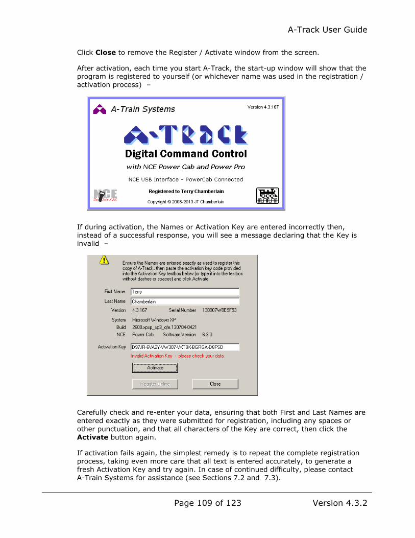
A-Track User Guide
Page 109 of 123 Version 4.3.2
Click Close to remove the Register / Activate window from the screen.
After activation, each time you start A-Track, the start-up window will show that the program is registered to yourself (or whichever name was used in the registration / activation process) –
If during activation, the Names or Activation Key are entered incorrectly then, instead of a successful response, you will see a message declaring that the Key is invalid –
Carefully check and re-enter your data, ensuring that both First and Last Names are entered exactly as they were submitted for registration, including any spaces or other punctuation, and that all characters of the Key are correct, then click the Activate button again.
If activation fails again, the simplest remedy is to repeat the complete registration process, taking even more care that all text is entered accurately, to generate a fresh Activation Key and try again. In case of continued difficulty, please contact A-Train Systems for assistance (see Sections 7.2 and 7.3).

A-Track User Guide
Page 110 of 123 Version 4.3.2
7.2 Key Points to Note about Registration / Activation
While you are free to install as many copies of A-Track on different computers as you wish without charge, each installation will generate a unique serial number and will require to be separately registered and activated.
Once an A-Track installation is registered, the details are locked, and you cannot change the name of the Registered User nor the value of the Activation Key. If this creates a problem at any time in the future, then contact A-Train Systems for assistance (see below).
After registering A-Track on a particular computer, if you uninstall A-Track and then subsequently re-install the program, details of your registration / activation are retained in the Windows Registry so that the new installation of A-Track will still be registered. This will also be the case if you install a later, updated version of A-Track, although it is possible that some future major revision of the software may require re-registration.
However, if you perform any major upgrade or re-installation of software on your machine, particularly if you upgrade the Windows operating system, it is possible that the A-Track registration / activation information will be lost in the process. In this case, simply repeat the registration process to obtain a new activation key.
If you encounter any unusual difficulties regarding A-Track registration (or any other aspect of the program) then you should contact A-Train Systems either by submitting a Support Request, as described in the following Section 7.3, or through the Contact page on the website. You can also get in touch via e-mail by sending a message to [email protected].
7.3 Obtaining Support and Reporting Problems
Although every effort has been made to test A-Track as fully as possible, and to make the program as resilient as possible, it is impracticable to predict every situation under which the software will operate, especially given the complexity of modern computer operating systems, or to eliminate every last bug and error in the program code (and any programmer who declares otherwise is seriously deluded !).
Hence, if you find that A-Track does not behave as you expect under some circumstances (or even crashes), then you should submit a Support Request or Problem Report, by clicking on Help on the menu bar and then selecting Support / Report Problems from the drop-down menu –
Clicking on Support / Report Problems will open a window displaying a basic set of instuctions on how to proceed with sending a request for support or assistance to A-Train Systems.

A-Track User Guide
Page 111 of 123 Version 4.3.2
If the computer on which A-Track is running has an active connection to the Internet then you can proceed immediately to submit your support request.
Enter a name in the Your Name textbox in the displayed window. The name can be your own, or you can use the name of your club, for example. Any combination of characters can be entered except for an ampersand (&) which will be replaced with a ‘+’ symbol. If you have previously registered this copy of A-Track, the Registered User Name will be entered automatically into the textbox –
If you do not wish to proceed with your request at this time, then you can click Close to remove the window. Otherwise click Request Support to connect to the Internet and to the Support page of the A-Train Systems website. A-Track will copy your entered Name, together with the Version and Serial Number of the installed A-Track program (displayed in the Support / Report Problems window above as 4.3.165 and 130928A8E9F53), details of the version and build of Windows installed on this computer, and the type and software version of the NCE System to which you last connected, to the webpage where you can complete your request / report details, as shown on the following page.
As noted in the introductory text on the Support webpage, before you submit a request for help with a problem, it would be very much appreciated if you could carefully check the relevant sections of this Reference Manual (or the A-Track Help Topics), just in case you have misinterpreted the way in which A-Track is supposed to work. That said, if you are unhappy, for any reason, with the way A-Track handles your requirements, please go ahead and submit the details of the problem.
Enter your e-mail address in each of the two textboxes below the displayed Serial Number, taking care to type the address correctly, complete the Subject and Details textboxes, and then enter the six characters shown in the box with the multi-coloured backgound into the final Security Code textbox. The characters are selected from the numerals 0 to 9, and the uppercase letters A to F –

A-Track User Guide
Page 112 of 123 Version 4.3.2

A-Track User Guide
Page 113 of 123 Version 4.3.2
If you would like a copy of your submitted request / report to be e-mailed to you for your own records, click to tick the Send a copy to yourself checkbox. Finally, click the Submit button to complete the request process. Your entries will be checked for validity, and error messages will be displayed on the page if any entry is judged to be incorrect or inconsistent. If this occurs, simply correct the erroneous text, enter the new security code which will be displayed, and click Submit again.
Once all entries are accepted, an acknowledgement message will be displayed as shown below. Due to the limited resources available, on some occasions it may not be possible to reply individually to your submitted support request or problem report, but you will be informed when any necessary corrections have been incorporated in a future release of the software.
Note that A-Train Systems will never disclose your e-mail address to any other person or organisation, and will only use the address, on occasion, to acknowledge your submitted request, and to let you know when an applicable A-Track software update is available.
Although the A-Track program and its on-going support are provided to you completely without charge, if you have found A-Track to be useful and a benefit in pursuing your model railroading activities, then you might like to consider making a donation to assist in the cost of maintaining the website and the equipment used to develop the software further.
A-Track User Guide
Page 114 of 123 Version 4.3.2
You can donate any sum you wish, in a completely safe and secure manner, by clicking the Donate button shown above. This will connect you to the PayPal secure website where you can use any credit or debit card to make your donation, even if you do not have a PayPal account of your own. Any amount you choose to contribute will be gratefully received.
If the computer on which you run A-Track is not connected to the Internet, then you can access A-Track Support manually by going to the A-Train Systems Support webpage at http://www.a-train-systems.co.uk/support.php from any computer which does have an Internet connection.
Carefully enter your Name together with the installed program Version (4.3.165 in the example - see Help / About or Help / Support), and the Serial Number (130928A8E9F53 in the example - see Help / Register or Help / Support), complete the other entries as shown previously, and click the Submit button to complete your support request or problem report.
Alternatively, you can submit a support request or problem report via an e-mail to [email protected] containing full details together with your name, the program Version, and the installed Serial Number. In this case, every effort will be made to return an acknowledgement (but not necessarily a solution) to you within 48 hours.
7.4 Suggestions or Proposals for Improvement
As well as reporting errors and problems that you have found with any part of the software, you are also very welcome to propose any improvements that you would like to see in the way A-Track operates, or any additional features or facilities that you feel would increase the usefulness of the program.
To make any suggestions, please use the Support Request / Problem Report form, which you can access by clicking on Help on the menu bar and then selecting Support / Report Problems from the drop-down menu, as explained in the preceding Section 7.3.

A-Track User Guide
Page 115 of 123 Version 4.3.2
8 A-TRACK MENUS - REFERENCE
A description is provided in the following sections of the specific action performed by clicking each entry in each of the main A-Track menus, together with a note of any defined keyboard shortcut, ie. the key, or combination of keys, which can be pressed to perform that menu action immediately, together with any corresponding icon on the A-Track toolbar.
8.1 File
New – Opens a new Item List containing a single Blank Item. If an Item List is already loaded and has been changed in any way, then you are asked whether you wish to save the current Item List before it is replaced with the new List.
Shortcut Key : Ctrl-N Toolbar Icon :
Open – Opens an existing Item list. A standard Windows Open File Dialog is displayed, allowing you to navigate to the folder where the target Item List is held. If an Item List is already loaded and has been changed in any way, then you are asked whether you wish to save the current Item List before it is replaced with the selected Item List.
Shortcut Key : Ctrl-O Toolbar Icon :
Open Merge - Opens an existing Item list and adds its constituent Items to the end of the currently displayed Item List. A standard Windows Open File Dialog is displayed, allowing you to navigate to the folder where the Item List to be merged is held.
Shortcut Key : Ctrl-M Toolbar Icon :
Close – Closes the currently open Item List and removes it from display. If the Item List has been changed in any way, then you are asked whether you wish to save the current Item List before it is closed.
Save As – Saves the currently open Item List to permanent storage. A standard Windows Save File Dialog is displayed, allowing you to navigate to the drive and folder where the current Item List is to be saved. You can either enter a new filename under which to save the Item List, or click Save to save the List under its existing filename. If you choose the latter option then you are asked to confirm that you wish to overwrite the previous version of the Item List.
Shortcut Key : Ctrl-S Toolbar Icon :
Save Checked – Saves only those Items in the open Item List which are checked, ie. where the checkbox to the left of the Item Description is ticked, to permanent storage. A standard Windows Save File Dialog is displayed, allowing you to navigate to the drive and folder where the current Item List is to be saved. You can either enter a new filename under which to save the Item List, or click Save to save the List under its existing filename. If you choose the latter option then you are asked to confirm that you wish to overwrite the previous version of the Item List. Note : By choosing to overwrite the existing Item List you will permanently lose all those Items which were not checked – so make sure that you really want to eliminate them, or have another copy stored safely elsewhere.
Shortcut Key : None Toolbar Icon :

A-Track User Guide
Page 116 of 123 Version 4.3.2
Properties – Displays details of the currently-open Item List file including file format, folder location, file size, number of Items, and the dates of creation and last modification.
Print – Allows you to print all or part of the Item List and details of selected Items to any printer selected from those installed on the computer, or to an output file, and to select the basic print format and characteristics that you require.
Shortcut Key : Ctrl-P Toolbar Icon :
Most Recently Used Files – Shows the filenames of the most-recently opened Item Lists. Click on any displayed name to open the corresponding Item List. Up to eight filenames can be displayed in the list – when you open the ninth distinct Item List then the oldest filename is dropped from the list to make way for that of the latest Item List.
Exit - Closes any currently open Item List, and removes it from display, before terminating the A-Track program. If the Item List has been changed in any way, then you are asked whether you wish to save the current Item List before it is closed.
Shortcut Key : None Window Close button : or
8.2 Edit
Undo – Restores the Item List to the state it was in prior to the immediately preceding Edit action. This includes returning an edited Item and its constituent data values to their state before they were changed. Up to 32 Edit actions can be recorded and undone. If more than 32 Edit actions are performed then only the most recent 32 remain in the record, and can subsequently be reversed.
Shortcut Key : None Toolbar Icon :
Redo – Re-performs the Edit action which was reversed by an immediately preceding Undo operation. This includes returning an Item and its constituent data values to their edited state. Redo is not active until an Undo action has been performed.
Shortcut Key : None Toolbar Icon :
Find – Searches the Item List for Items whose Description. Primary Address, or Extended Address match an entered string of characters. The direction of search can be selected, and the search parameters changed, at any time to refine the Find operation.
Shortcut Key : Ctrl-F Toolbar Icon :
Cut – Deletes from the Item List all Items which are currently selected, and places a copy of each of these Items in the Copy Buffer, replacing any previous contents of the Buffer.
Shortcut Key : Ctrl-X Toolbar Icon : (Item Pop-Up menu)
Cut Append - Deletes from the Item List all Items which are currently selected, and adds a copy of each of these Items to the current contents of the Copy Buffer.
Shortcut Key : Ctrl-Z Toolbar Icon : (Item Pop-Up menu)

A-Track User Guide
Page 117 of 123 Version 4.3.2
Copy - Copies from the Item List all Items which are currently selected, and places a copy of each of these Items in the Copy Buffer, replacing any previous contents of the Buffer.
Shortcut Key : Ctrl-C Toolbar Icon : (Item Pop-Up menu)
Copy Append - Copies from the Item List all Items which are currently selected, and adds a copy of each of these Items to the current contents of the Copy Buffer.
Shortcut Key : Ctrl-D Toolbar Icon : (Item Pop-Up menu)
Paste - Retrieves all Items currently in the Copy Buffer, and adds a copy of each of these Items to the displayed Item List. The contents of the Copy Buffer remain unchanged, and no Item in the displayed Item List is either changed or overwritten - even if it is identical to one of the added Items (such Items are thus duplicated).
Shortcut Key : Ctrl-V Toolbar Icon :
Empty Buffer - Clears completely all Items currently in the Copy Buffer. This action can be neither reversed nor undone - so any Items which were Cut to the Buffer will be lost permanently.
Shortcut Key : Ctrl-E Toolbar Icon :
Insert Blank Item - Adds a new Blank Item to the displayed Item List, ready for its description and parameters to be set. Note that you do not have control over where in the Item List the inserted Item will appear - this depends on the current Sort settings.
Shortcut Key : Shift-Insert Toolbar Icon :
Delete Item - Deletes from the Item List all Items which are currently selected. The deleted Items are not moved to the Copy Buffer, but the action can be reversed by using the Undo facility.
Shortcut Key : Delete Toolbar Icon : (Item Pop-Up menu)
Check All - Places tick marks in the checkboxes to the left of the Descriptions of all Items in the displayed Item List. Such Items are then said to be ‘checked’ (rather than selected). The action can be reversed by using the Undo facility.
Check Selected - Places tick marks in the checkboxes to the left of the Descriptions of those Items in the displayed Item List which have been highlighted. Such Items are then said to be ‘checked’ (as well as selected). The action can be reversed by using the Undo facility.
Invert Checked - Reverses the state of the checkboxes to the left of the Descriptions of all Items in the displayed Item List, ie. places a tick mark in each checkbox which is currently empty, and removes the tick mark from any Item which is currently checked. The action can be reversed by using the Undo facility.
Note : To remove tick marks from all Items in the Item List, use Check All followed by Invert Checked.
Select All - Selects (ie. highlights) all Items in the displayed Item List.
Shortcut Key : Ctrl-A Toolbar Icon : None

A-Track User Guide
Page 118 of 123 Version 4.3.2
Invert Selection - Reverses the state of selection of all Items in the displayed Item List, ie. highlights each Item which is not currently selected, and removes the highlight from any Item which is currently selected. The action can be reversed by using the Undo facility.
Note : To remove selection from all Items in the Item List, use Select All followed by Invert Selection. Alternatively, simply click on any Item - this will remove highlighting from all Items except the Item which has just been clicked.
Edit / Run Macros – Displays the contents of a selected Macro backup file in the Macro Edit window or, optionally, displays a blank Macro Edit window in which new Macros can be created, or into which a selected set of the Macros stored in a connected NCE Power Pro Command Station can be loaded for review.
8.3 View
Toolbar - Hides the A-Track toolbar icons. Click again to show the icons once more. The menu entry shows a tick mark when the toolbar icons are displayed.
Status Bar - Hides the A-Track status bar. Click again to show the status bar once more. The menu entry shows a tick mark when the status bar is displayed.
Show Checked Only – Displays only those Items which are ‘checked’ ie. have tick marks in the checkboxes to the left of the Descriptions. Click again to display the full Item List again. The menu entry shows a tick mark when only ‘checked’ Items are displayed.
Note : This action does not remove any Item from the Item List – it simply hides ‘unchecked’ Items from view, which can be useful when dealing with long Lists.
Large Icons - Displays the Item List using the Large Icon view, ie. each Item is shown by a large icon corresponding to its Type, with a label taken from the Item Description (abbreviated if necessary) and the Item’s checked status. The Item List is displayed in as many columns as will fit within the A-Track window.
Small Icons - Displays the Item List using the Small Icon view, ie. each Item is shown by a small icon corresponding to its Type, with a label taken from the Item Description (abbreviated if necessary) and the Item’s checked status. The Item List is displayed in as many columns as will fit within the A-Track window.
List - Displays the Item List using the List view, ie. each Item is shown by a small icon corresponding to its Type, with a label taken from the Item Description (abbreviated if necessary) and the Item’s checked status. The Item List is displayed with one Item per row.
Details - Displays the Item List using the Details view, ie. the Item List is displayed with one Item per row and with ten columns to show the Item’s Description, Type, Status Flags, Primary Address (Consist Address for Consists, Decoder Address for Accessories), Extended Address (blank for Consists, selected Output Address for Accessories), Controller to which the Item is currently allocated (only used with NCE Power Pro Systems), Speed Step precision, current Speed and Direction, Headlight state (the last two only used with NCE Power Pro Systems), and state of Functions 1 to 8 (or Outputs 1 to 8 for Accessories), respectively. The Description field also contains the Item’s checked status and a small icon corresponding to its Type.

A-Track User Guide
Page 119 of 123 Version 4.3.2
Note : Either the Item’s Primary or Extended Address (Decoder or Output Address for Accessories) will be preceded by a ‘>’ character to indicate which Address will be active when the Item is under individual control on the layout. When the Item Type is Multiple (a member of a Consist) then the Consist Address will be shown in the inactive Address column, instead of either the Primary or the Extended Address, and will be preceded by an ‘=’ character.
Arrange Icons -
• by Description - Sorts the displayed Items into alphabetic order according to the text of the Item’s Description. Clicking on this menu entry again will change the Item sort order from ascending to descending or vice versa.
• by Type - Sorts the displayed Items into alphabetic order according to the Item’s Type (Loco, Consist, Multiple, or Accessory). Clicking on this menu entry again will change the Item sort order from ascending to descending or vice versa.
• by Flags - Sorts the displayed Items into alphabetic order according to the state of the Item’s Status Flags (Active, Edited, and Not Programmed). Clicking on this menu entry again will change the Item sort order from ascending to descending or vice versa.
• by Primary Address - Sorts the displayed Items into numeric order according to the value of the Item’s Primary (or Consist or Accessory Decoder) Address. Clicking on this menu entry again will change the Item sort order from ascending to descending or vice versa.
Note : The preceding ‘>’ character, to indicate that the Primary Address is active for an Item, or ‘=’ character to indicate membership of a Consist, is taken into account when sorting, so that all Items with an active Primary or Decoder Address, or in a Consist, will be grouped together before sorting into numeric order.
• by Extended Address - Sorts the displayed Items into numeric order according to the value of the Item’s Extended (or Accessory Output) Address. Clicking on this menu entry again will change the Item sort order from ascending to descending or vice versa.
Note : The preceding ‘>’ character, to indicate that the Extended or Output Address is active for an Item, or ‘=’ character to indicate membership of a Consist, is taken into account when sorting, so that all Items with an active Extended or Output Address, or in a Consist, will be grouped together before sorting into numeric order.
• by File Order - Sorts the displayed Items into the order in which they are held within the Item List’s stored file. This order corresponds (approximately) to the order in which Items have been added to the Item List. Note that, whenever an Item is changed or modified in any way, it is moved to the end of the Item List.
Items can also be sorted into File Order by clicking on the toolbar icon.
One (and only one) of the Arrange Icons sub-menu entries will always show a tick mark to indicate the current sort order of the Item List.

A-Track User Guide
Page 120 of 123 Version 4.3.2
Note : In Details view, the Item List can be sorted by any of the above categories (apart from File Order) simply by clicking on the appropriate column header. Clicking on the same column header again will change the Item sort order from ascending to descending or vice versa. When clicked, the column header will show a small icon to indicate ascending ( ) or descending ( ) sort order.
Line Up Icons - In the current release of A-Track this only has an effect in Small Icons and Large Icons views where, if the icons are shown in a few columns, this menu option will increase the number of columns to fill the full width of the window. Normally, in Large Icons and Small Icons views, the Item entries automatically realign themselves after any Item has been dragged to a different position within the window.
Consist Status – Item List / Cmnd Stn - Displays a window showing all Consists which are currently defined in either an NCE Power Pro Command Station Consist table or the A-Track Item List, or both, together with a list of the Locomotive addresses assigned to the selected Consist within the Power Pro Command Station (but not necessarily in the Item List).
Where any Locomotive assigned to a Consist is identified in the Item List, its description is displayed alongside the address. Click on any Consist Address to display the status and assignment details of that Consist. Where appropriate, details of the selected Consist can be copied from the Item List to the NCE Power Pro Command Station (‘activated’) or from the Command Station to the Item List (‘transferred’) - in either case overwriting any previous definition of that Consist held in the destination.
Consist Status – View Backup File - Displays a window showing all Consists which are currently defined in either a selected Consist backup file or the A-Track Item List, or both, together with a list of the Locomotive addresses assigned to the selected Consist within the Consist backup file (but not necessarily in the Item List).
Where any Locomotive assigned to a Consist is identified in the Item List, its description is displayed alongside the address. Click on any Consist Address to display the status and assignment details of that Consist. Where appropriate, details of the selected Consist can be copied from the Consist backup file to the Item List (‘transferred’), overwriting any previous definition of that Consist held in the destination. However, Consists cannot be copied to an attached NCE Power Pro Command Station (‘activated’ – where the Consist address is programmed into the actual assigned Locomotives on the track) directly from a backup file. The Consist must first be transferred into the A-Track Item List.
Refresh Item Allocation & Status – Initiates an immediate rescan and update of the NCE Handheld Cab allocations and status shown the righthand columns of the Item List when using Details view (only enabled when connected to an NCE Power Pro Command Station).
Although clicking on the toolbar icon (shown below) simply initiates a rescan, clicking on the View menu option itself will display a prompt allowing you to disable or continue the periodic scan of attached NCE Cabs. Disabling automatic scans of NCE Cab status is useful when you want to adjust parameters relating to the NCE Power Pro Command Station or Cabs, or change Consist or Macro settings, without being interrupted periodically. The tick mark next to the option on the View menu will be removed whenever periodic scans of attached NCE Cabs are disabled. Click again on the option when you wish to resume automatic scans of NCE Cab status.
A-Track User Guide
Page 121 of 123 Version 4.3.2
Shortcut Key : None Toolbar Icon :
Note : Your choices of view type and format, and of whether to enable or disable periodic scans of attached NCE Cabs, are saved by A-Track and will be applied each time the program is started.
8.4 Item
Edit CVs - Opens an Edit Configuration Variables window for the currently selected Item. If several Items are selected (highlighted) then the Edit CVs window is opened for the last-selected Item (identified in the Item List by an outline box drawn around the appropriate Item). The Edit CVs window allows you to view, modify, and save values for each of that Item’s Configuration Variables as well as a number of other parameters.
Note : Separate Edit CVs windows can be opened simultaneously on the screen for as many Items as you wish, so that you can easily compare, and transfer, CV values between Items.
Shortcut Key : None Toolbar Icon : (Item Pop-Up menu)
Allocate NCE Cab – Only enabled with NCE Power Pro Systems - Opens an Allocate Item to NCE Cab window for the currently selected Item. If several Items are selected (highlighted) then the Allocate Item window is opened for the last-selected Item (identified in the Item List by an outline box drawn around the appropriate Item). The Allocate Item to NCE Cab window allows you to allocate control of the selected Item to any NCE Handheld Controller (Cab), via the NCE Power Pro Command Station, and to adjust the Item’s position in the selected Cab’s Recall list.
Note : If the Item currently selected (highlighted) in the Item List has been allocated to an NCE Handheld Controller, then the Allocate NCE Cab entry on the Item menu changes to Deallocate, and the Operate option is disabled. The identity of the allocated NCE Cab appears in the Controller column of the Item List row corresponding to the Item under control.
Shortcut Key : None Toolbar Icon : None (Item Pop-Up menu)
Deallocate - Only enabled with NCE Power Pro Systems - Opens a Deallocate Item from NCE Cab window for the currently selected Item. If several Items are selected (highlighted) then the Deallocate Item window is opened for the last-selected Item (identified in the Item List by an outline box drawn around the appropriate Item). The Deallocate Item to NCE Cab window allows you to remove the selected Item from the NCE Handheld Controller (Cab) to which it has been allocated.
Note : Once an Item has been deallocated, and that Item is selected in the Item List, the Deallocate entry on the Item menu changes back to the Allocate NCE Cab option, and the Operate option is enabled.
Shortcut Key : None Toolbar Icon : None (Item Pop-Up menu)
Operate - Opens an Operate Item window for the currently selected Item. If several Items are selected (highlighted) then the Operate Item window is opened for the last-selected Item (identified in the Item List by an outline box drawn around the appropriate Item). The Operate Item window provides a ‘soft’ controller on the screen, giving you control of the Item’s speed, direction, and functions for Locomotive Items, or output states for Accessory Items, using mouse and keyboard.

A-Track User Guide
Page 122 of 123 Version 4.3.2
Note : Up to eight Operate Item windows, corresponding to eight selected Items, can be opened simultaneously on the screen, so that you can (in theory) control up to eight Items directly from the PC. The facility should be used with caution as it is very easy to lose track (literally) of which Item is under control from a particular Operate Item window.
Shortcut Key : None Toolbar Icon : (Item Pop-Up menu)
8.5 Help
Help Topics - Displays a comprehensive set of Help pages containing all of the information contained in the Reference Manual. The standard Windows HTML Help format is employed, with all Help pages accessible from a Contents list. Although an Index facility is not available, there is a full Search capability which can be employed to locate all pages containing a particular word or phrase.
Note : Help pages are context-sensitive, so that, when you press the F1 shortcut key at any point when using A-Track, the Help page most appropriate to that part of the program which is currently active will be displayed.
Shortcut Key : F1 Toolbar Icon :
Start-Up Tutorial - displays the first page of the ‘Welcome to A-Track – Your DCC Buddy’ demonstration and tutorial, ready to take you through the basic features of the program’s operation.
Note : A tick next to this menu entry indicates that the ‘Welcome to A-Track’ tutorial will be displayed whenever A-Track is started. If you do not wish this to occur, first click this entry to display the ‘Welcome to A-Track’ help page, then tick the ‘Do not display at start-up’ checkbox located below the tutorial text before closing the window.
Register / Activate – Opens a window which displays information relating to the version of A-Track which is running, the Serial Number generated when you installed A-Track, details of the version and build of Windows installed on this computer, the type and software version of the NCE System to which you last connected and the current registration / activation status.
If this copy of A-Track has not been registered, the window allows the user to enter his or her name, and then to access an online facility which will generate an Activation Key (code). The Key should then be copied by the user into the Register / Activate window in order to complete registration. After registration / activation, the window displays the Registered User’s name and the Activation Key value.
Support / Report Problems – Opens a window which displays information relating to the version of A-Track which is running, the Serial Number generated when you installed A-Track, details of the version and build of Windows installed on this computer, and the type and software version of the NCE System to which you last connected. If this copy of A-Track has been registered, the window also shows the Registered User Name. Otherwise, enter your name and then access an online facility which allows you to submit a request for support or a report of a problem with A-Track.
About A-Track - Opens a window displaying the Version number of the program, a brief description, and copyright and trademark information –

A-Track User Guide
Page 123 of 123 Version 4.3.2
8.6 Pop-Up
When an Item in the Item List is right-clicked, a pop-up menu appears and offers a set of actions selected from the Item and Edit menus. The details are summarised below, but see the entries in the preceding Item and Edit menu descriptions for more complete information.
Edit CVs - Opens an Edit Configuration Variables window for the selected Item.
Allocate NCE Cab - Opens an Allocate Item to NCE Cab window for the selected Item to allow you to allocate control of the selected Item to an NCE Handheld Controller (only displayed if connected to an NCE Power Pro System, and the Item is not currently allocated).
Deallocate - Removes the selected Item from control by the allocated NCE Handheld Controller (only displayed if connected to an NCE Power Pro System, and the Item is currently allocated).
Operate - Opens an Operate Item window for the selected Item to give you control of the Item’s speed, direction, and functions for Locomotive Items, or output states for Accessory Items, from the PC screen (only enabled if the Item is not currently allocated).
Delete Item - Deletes the Item from the Item List (Item is not copied to the Copy Buffer).
Cut - Deletes the Item from the Item List, and places a copy of the Item in the Copy Buffer, replacing any previous contents of the Buffer.
Cut Append - Deletes the Item from the Item List, and adds a copy of the Item to the current contents of the Copy Buffer.
Copy - Copies the Item from the Item List, and places a copy of the Item in the Copy Buffer, replacing any previous contents of the Buffer.
Copy Append - Copies the Item from the Item List, and adds a copy of the Item to the current contents of the Copy Buffer.