a tunable electromagnetic vibration absorber ...flash.lakeheadu.ca/~kliu/jsv_06.pdfjournal of sound...
TRANSCRIPT

ARTICLE IN PRESS
JOURNAL OFSOUND ANDVIBRATION
0022-460X/$ - s
doi:10.1016/j.js
�CorrespondE-mail addr
Journal of Sound and Vibration 295 (2006) 708–724
www.elsevier.com/locate/jsvi
A tunable electromagnetic vibration absorber:Characterization and application
Jie Liu, Kefu Liu�
Department of Mechanical Engineering, Lakehead University, 955 Oliver Road, Thunder Bay, Ont., Canada P7B 5E1
Received 2 February 2005; received in revised form 22 December 2005; accepted 17 January 2006
Available online 11 April 2006
Abstract
The paper presents a newly designed electromagnetic vibration absorber (EMVA), whose stiffness is on-line tunable. The
EMVA is capable of suppressing vibration of the primary system excited by a harmonic force with a variable frequency.
The EMVA consists of a clamped–clamped aluminum beam and a permanent magnet that is embedded in the center of the
beam and placed between two poles of a C-shaped electromagnet. By varying the current of the electromagnet, stiffness of
the EMVA can be adjusted instantaneously such that the absorber frequency can be tuned. A detailed characterization of
the EMVA is presented. The effective stiffness of the absorber is determined numerically and validated experimentally. To
test its effectiveness in vibration suppression, the EMVA is used to track two types of the exciting frequency variations:
multi-step and linear. The response of the absorber mass is used to tune the EMVA to ensure that the absorber frequency
equals the exciting frequency.
r 2006 Elsevier Ltd. All rights reserved.
1. Introduction
Tunable vibration absorbers belong to the family of semi-active control systems. Semi-active controlsystems are attracting more research interest in the field of vibration control, since they combine theadvantages of both passive and active control systems. On one hand, they preserve the reliability of the passivecontrol systems even in the event of power loss; on the other hand, they possess the versatility and adaptabilityof the active systems without a great amount of power consumption. Generally, the mechanical properties ofthe semi-active systems, such as the stiffness and/or the damping value, can be adjusted based on the feedbackfrom the measured response and/or the excitation. Several variable stiffness vibration absorbers have beenproposed. Stiffness variation of the device reported in Ref. [1] was achieved by varying the effective number ofcoils in a helical spring used as the absorber stiffness. The same vibration absorber was used to study non-collocated adaptive-passive vibration control in Ref. [2]. A vibration absorber developed in Ref. [3] consists ofa flexible cantilever beam attached by a mass at its free end. By varying the length of the beam, the absorberfrequency can be varied. A variable stiffness device proposed in Ref. [4] has four coil springs arranged ina plane rhombus configuration. The aspect ratio of the rhombus configuration can be varied by a linear
ee front matter r 2006 Elsevier Ltd. All rights reserved.
v.2006.01.033
ing author. Tel.: +1 807 343 8634; fax: +1 807 343 8928.
ess: [email protected] (K. Liu).
ARTICLE IN PRESSJ. Liu, K. Liu / Journal of Sound and Vibration 295 (2006) 708–724 709
electromechanical actuator to achieve a continuous variation of the absorber stiffness. In Ref. [5] a variablestiffness absorber similar to the one developed in Ref. [3] was used to compare two different tuning algorithms.It is noted that all the above tunable devices involve an electro-mechanically driven system. As a result, a slowreaction speed may become the main concern for these types of stiffness control devices. Alternatively,damping is sometimes added to the absorber systems to improve the effective bandwidth of operation.Damping value can be made on-line adjustable by utilizing a variable-orifice valve to alter the resistance to theflow of a conventional hydraulic fluid damper [6,7]. Friction dampers have also been widely studied as anotherapproach in semi-active vibration control [8,9]. Most noticeably, electro-rheological or magneto-rheologicaldampers feature a broad-bandwidth modulation of the damping characteristics through the variation of anelectrical or magnetic field [10–12]. However, when adding the damping into the system, the performance ofthe absorber at the design frequency is sacrificed.
Over the past decade, various devices based on magnetism or electromagnetism have been used tosuppress vibration. The electromagnetic servomechanism developed in Ref. [13] consists of two pairedelectromagnets and permanent magnets. When the electromagnets are energized, interacting forces areproduced between the paired electromagnets and permanent magnets. The device was used in the study ofactive vibration control. In Ref. [14] permanent magnets were used to build an extremely soft spring for thepurpose of vibration isolation. A hybrid-type active vibration isolation system developed in Ref. [15] uses bothelectromagnetic and pneumatic forces. In Ref. [16] an electromagnetic device was designed to parametricallyexcite the experimental beam. The phenomenon of eddy current has been explored to develop magneticdampers [17–19].
This paper presents a newly designed electromagnetic vibration absorber (EMVA). Similar to the devicesreported in Refs. [1–5] the device developed in this study is a variable stiffness one. However, a notabledifference is that the present device is non-contact, with non-mechanical motion, and the stiffness can bechanged instantly. Also, different from the electromagnetic devices referred above, the present system istunable on-line. It should be noted that in Refs. [13–16] approximate approaches were employed to establishthe electromagnetic interaction. An extensive literature search has indicated that a method to quantify thestiffness characteristics of the EMVA is not readily available. The detailed stiffness characterization presentedin this study is useful for the design of similar devices.
The following sections of the paper are organized as follows: In Section 2, the developed EMVA isintroduced and an experimental setup used to test the EMVA is explained. In Section 3, characterization of theEMVA is presented. In Section 4, an experimental calibration is conducted and the performance of the EMVAis tested. In Section 5, the conclusions of the study are given.
2. Electromagnetic vibration absorber
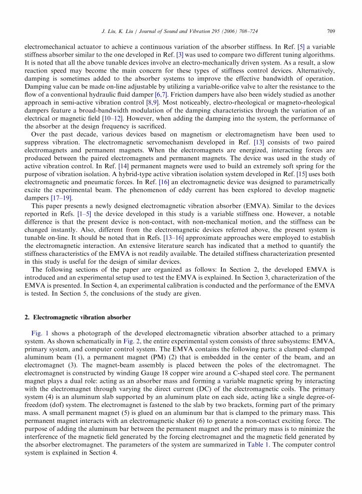
Fig. 1 shows a photograph of the developed electromagnetic vibration absorber attached to a primarysystem. As shown schematically in Fig. 2, the entire experimental system consists of three subsystems: EMVA,primary system, and computer control system. The EMVA contains the following parts: a clamped–clampedaluminum beam (1), a permanent magnet (PM) (2) that is embedded in the center of the beam, and anelectromagnet (3). The magnet-beam assembly is placed between the poles of the electromagnet. Theelectromagnet is constructed by winding Gauge 18 copper wire around a C-shaped steel core. The permanentmagnet plays a dual role: acting as an absorber mass and forming a variable magnetic spring by interactingwith the electromagnet through varying the direct current (DC) of the electromagnetic coils. The primarysystem (4) is an aluminum slab supported by an aluminum plate on each side, acting like a single degree-of-freedom (dof) system. The electromagnet is fastened to the slab by two brackets, forming part of the primarymass. A small permanent magnet (5) is glued on an aluminum bar that is clamped to the primary mass. Thispermanent magnet interacts with an electromagnetic shaker (6) to generate a non-contact exciting force. Thepurpose of adding the aluminum bar between the permanent magnet and the primary mass is to minimize theinterference of the magnetic field generated by the forcing electromagnet and the magnetic field generated bythe absorber electromagnet. The parameters of the system are summarized in Table 1. The computer controlsystem is explained in Section 4.

ARTICLE IN PRESS
Fig. 1. Photograph of the experimental set-up.
Fig. 2. Schematic of the entire experimental system.
J. Liu, K. Liu / Journal of Sound and Vibration 295 (2006) 708–724710
3. Characterization of the EMVA
Characterization of the EMVA focuses on determination of the variable range of its stiffness. Suchinformation is of importance for the design and implementation of the EMVA. Unfortunately, a systematical

ARTICLE IN PRESS
Table 1
System parameters
Symbol Description Value
ma Absorber mass 0.151 kg
m Primary mass 3.074 kg
ca Damping coefficient of the absorber system 0.18Ns/m
c Damping coefficient of the primary system 3.71Ns/m
R1 Inner radius of the electromagnetic coils 11mm
R2 Outer radius of the electromagnetic coils 20mm
L Circumference of the electromagnet 314.16mm
N Turns of the coils 784
m0 Permeability of free space 4p� 10�7H/m
d The gap space between two pole faces of the electromagnet 42.0mm
l Length of the PM 48.0mm
w Height of the PM 22.0mm
h Thickness of the PM 10.0mm
Fig. 3. Three springs involved in the EMVA.
J. Liu, K. Liu / Journal of Sound and Vibration 295 (2006) 708–724 711
method to calculate the stiffness of such a device has not been found in the literature. In what follows, adetailed characterization procedure is presented. It is expected that the developed approach is useful for thedesign of similar devices. As shown in Fig. 3, three springs are involved in the EMVA, namely, a constantspring kc1 created by the absorber beam, a constant spring kc2 due to the interaction between the PM and thecore of the electromagnet, and a variable spring kn due to the interaction between the PM and theelectromagnet. To determine kn and kc2, the theory of electromagnetism is explored to obtain the relationshipbetween the magnetic force and the displacement of the absorber mass. With this relationship, the stiffness canbe established.
3.1. Magnetic stiffness due to the interaction between the electromagnet and the PM
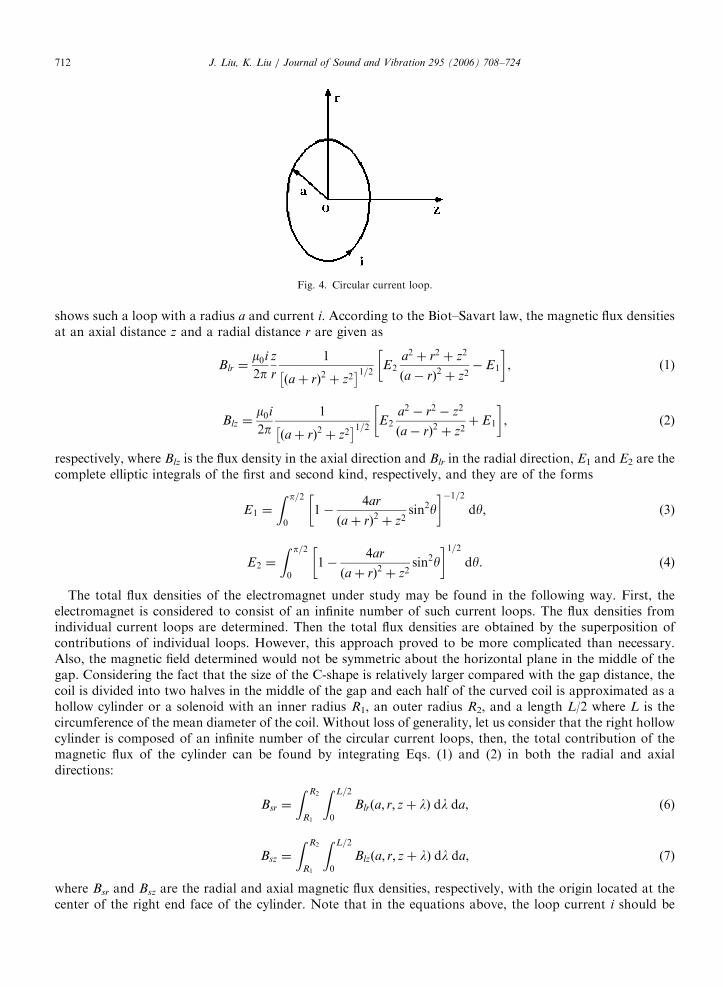
The approach used is to first determine the interaction force between the PM and the magnetic fieldproduced by the electromagnet. The stiffness is then equal to the derivative of the force with respect todistance. The magnetic flux density within the gap of the C-shaped electromagnet can only be determinednumerically. Although a commercial finite element analysis package may be employed, this study took adifferent strategy. The Biot–Savart law of magnetostatics determines the constant magnetic field of an elementcarrying a steady current [20]. A circular current loop can be considered to be a basic element of a coil. Fig. 4
ARTICLE IN PRESS
Fig. 4. Circular current loop.
J. Liu, K. Liu / Journal of Sound and Vibration 295 (2006) 708–724712
shows such a loop with a radius a and current i. According to the Biot–Savart law, the magnetic flux densitiesat an axial distance z and a radial distance r are given as
Blr ¼m0i2p
z
r
1
ðaþ rÞ2 þ z2� �1=2 E2
a2 þ r2 þ z2
ða� rÞ2 þ z2� E1
� �, (1)
Blz ¼m0i
2p1
ðaþ rÞ2 þ z2� �1=2 E2
a2 � r2 � z2
ða� rÞ2 þ z2þ E1
� �, (2)
respectively, where Blz is the flux density in the axial direction and Blr in the radial direction, E1 and E2 are thecomplete elliptic integrals of the first and second kind, respectively, and they are of the forms
E1 ¼
Z p=2
0
1�4ar
ðaþ rÞ2 þ z2sin2y
� ��1=2dy, (3)
E2 ¼
Z p=2
0
1�4ar
ðaþ rÞ2 þ z2sin2y
� �1=2dy. (4)
The total flux densities of the electromagnet under study may be found in the following way. First, theelectromagnet is considered to consist of an infinite number of such current loops. The flux densities fromindividual current loops are determined. Then the total flux densities are obtained by the superposition ofcontributions of individual loops. However, this approach proved to be more complicated than necessary.Also, the magnetic field determined would not be symmetric about the horizontal plane in the middle of thegap. Considering the fact that the size of the C-shape is relatively larger compared with the gap distance, thecoil is divided into two halves in the middle of the gap and each half of the curved coil is approximated as ahollow cylinder or a solenoid with an inner radius R1, an outer radius R2, and a length L/2 where L is thecircumference of the mean diameter of the coil. Without loss of generality, let us consider that the right hollowcylinder is composed of an infinite number of the circular current loops, then, the total contribution of themagnetic flux of the cylinder can be found by integrating Eqs. (1) and (2) in both the radial and axialdirections:
Bsr ¼
Z R2
R1
Z L=2
0
Blrða; r; zþ lÞ dl da, (6)
Bsz ¼
Z R2
R1
Z L=2
0
Blzða; r; zþ lÞ dl da, (7)
where Bsr and Bsz are the radial and axial magnetic flux densities, respectively, with the origin located at thecenter of the right end face of the cylinder. Note that in the equations above, the loop current i should be

ARTICLE IN PRESSJ. Liu, K. Liu / Journal of Sound and Vibration 295 (2006) 708–724 713
substituted by using
i ¼2NI
ðR2 � R1ÞL, (8)
where I is the coil current. Considering the complexity of the foregoing equations, numerical methods arecommonly employed. The total magnetic flux densities can then be found by the superposition of the fluxdensities from the right cylinder with those from the left cylinder. The total flux density is denoted as Bcr andBcz for the radial and axial direction, respectively. Fig. 5 shows the computed axial flux densities along thecenter line of the air gap.
A ferromagnetic core can significantly magnify the magnetic field produced by the coils, and such an effect isincluded by introducing an amplification number mr, which is the relative permeability of the steel core.Further, for a certain coil current, the flux available in the air gap is solely affected by the term mr/g and, thedenominator g is called the leakage factor, defined as the ratio of the total flux to the gap flux. Since the valueof mr/g varies with materials of the core, specific experimental setups, etc., it is customary to determine itexperimentally. Thus, a DC magnetometer (AlphaLab, Model: DCM) was used to measure the axial magneticflux density at the points along the centerline of the gap of the electromagnet. Four different amplitudes of DCcurrent were applied separately. The value mr/g was determined in the following way: a modified computedaxial flux density was found by multiplying a trial value mr/g to the computed Bcz; then, the squared errorbetween the measured axial flux density and the modified computed axial flux density was found; by varyingthe values of mr/g the squared error was minimized. It was found that by using the value of mr=g ¼ 27:5,minimum error resulted. Fig. 6 shows a comparison of the measured values and the computed values. Fig. 7
Fig. 5. Axial flux density along the centerline of the gap: dash-dot line, Bsz from the right cylindrical coils; dot line, Bsz from the left
cylindrical coils; solid line, Bcz.

ARTICLE IN PRESS
Fig. 6. Comparison of the measured values and the computed values for the axial flux density along the centerline of the gap:
(a) I ¼ 0:5A, (b) I ¼ 1:0A, (c) I ¼ 1:5A, (d) I ¼ 2:0A. Dot, experimental; solid line, analytical.
Fig. 7. The axial flux density of the electromagnet, I ¼ 1:5A.
J. Liu, K. Liu / Journal of Sound and Vibration 295 (2006) 708–724714
shows a 3D plot for the axial flux density distribution when a current of 1.5 A is applied to the electromagnet.It can be seen that the axial flux density Bz peaks along the centerline of the coils, reaches maximum on thepole faces, and becomes minimum in the middle of the air gap.

ARTICLE IN PRESSJ. Liu, K. Liu / Journal of Sound and Vibration 295 (2006) 708–724 715
With the flux density of the electromagnet available, the interaction force between the electromagnet and thePM is given by [20]
Fz ¼ �qW=qz, (9)
where W is the energy of interaction of the electromagnet and the PM. The energy W may be calculated as theintegral of the magnetization M of the PM times the potential from the electromagnet on the pole faces S1 andS2 of the PM (see Fig. 3). If jem
1 is the potential from the electromagnet on the pole face S1, and jem2 the
potential from the electromagnet on the pole face S2, then
W ¼ m0
ZS1
Mjem1 dS þ m0
ZS2
ð�MÞjem2 dS (10)
or
Fz ¼ �m0
ZS1
Mqjem
1
qzdS þ m0
ZS2
Mqjem
2
qzdS ¼M
ZS1
Bz1 dS �
ZS2
Bz2 dS
� �, (11)
where Bzi ¼ �m0qjemi
�qz; i ¼ 1; 2 is the axial flux density on the PM pole face i. Eq. (11) indicates that the
force Fz is proportional to the difference between the total flux over the pole face S1 and the total flux over thepole face S2. Note that, due to the symmetry of distributions of the radial magnetic flux, no net interactionforce exists in the radial direction. Fig. 8 shows the curves of the electromagnetic force Fz versus thedisplacement of the PM for four different coil currents. As shown in the figure, within the range of [�0.01,0.01] m, the force–displacement relationship is close to linear. The linearized curves are shown in the figure aswell, and their slopes (see Table 2) are the electromagnetic stiffness kn. It should be noted that a negativestiffness is obtained by applying a negative current. As analyzed in the next section, kc2 is negative as well.Therefore, it is very important to design the EMVA such that kc1 þ kc2 þ kn40. Also, when the displacementof the PM is too large, the nonlinearity of kn increases significantly. In the present design, the displacement ofthe PM (absorber mass) is restricted not to exceed 10mm. It is also understandable that when positive currents
-0.02 -0.015 -0.01 -0.005 0 0.005 0.01 0.015 0.02 -10
-8
-6
-4
-2
0
2
4
6
8
10
Displacement (m)
Net
forc
e (N
)
(a)
(d)
(c)
(b)
Fig. 8. Interaction force Fz versus the displacement of the PM with the origin at the gap center: (a) I ¼ �2:0A, (b) I ¼ �1:5A, (c)
I ¼ �1:0A, (d) I ¼ �0:5A. Solid line, analytical; dotted line, linearized.

ARTICLE IN PRESS
Table 2
Variable stiffness kn
Coil current (A) Analytical values (N/m) Experimental values (N/m)
Loading Unloading
�2.0 �468.15 �431.58 �416.99
�1.5 �351.10 �357.67 �327.44
�1.0 �234.08 �265.80 �216.80
�0.5 �117.04 �136.08 �103.11
0.5 117.04 106.72 142.43
1.0 234.08 215.01 251.88
1.5 351.10 328.88 347.86
2.0 468.15 424.73 424.73
J. Liu, K. Liu / Journal of Sound and Vibration 295 (2006) 708–724716
are applied, similar curves with positive slopes are obtained, which results in the positive electromagneticstiffness kn.
3.2. Magnetic stiffness due to the interaction between the PM and the Core
The orthorhombic PM with a dimension of l � w� h can be represented by two rectangles of surface poledensity s ¼ �M [20]. The flux density on the central axis at a distance z from the PM can be calculated as
Bz ¼m0Mp
sin�1lwffiffiffiffiffiffiffiffiffiffiffiffiffiffiffiffiffiffiffiffiffiffiffiffiffiffiffiffiffiffiffiffiffiffiffiffiffiffiffiffi
ðl2 þ 4z2Þðw2 þ 4z2Þ
q � sin�1lwffiffiffiffiffiffiffiffiffiffiffiffiffiffiffiffiffiffiffiffiffiffiffiffiffiffiffiffiffiffiffiffiffiffiffiffiffiffiffiffiffiffiffiffiffiffiffiffiffiffiffiffiffiffiffiffiffiffiffiffiffiffi
½l2 þ 4ðzþ hÞ2�½w2 þ 4ðzþ hÞ2�
q264
375. (12)
As many factors affect the production of PMs, their magnetic properties may vary. The Magnetic MaterialsProducers Association (MMPA) allows for up to 20% variation in magnetic energy from the published valuesfor a grade of magnetic material, this large swing in magnetic properties can greatly affect the performance ofany device using PMs. Because of this, the properties of a permanent magnet are normally determinedexperimentally. In order to identify the magnetization M, the magnetic flux density was measured by using theDC magnetometer at the points off the pole face and along the centerline of the PM. Comparing them withthat obtained by Eq. (12), M was found to be 395.8 kAm�1. Fig. 9 shows a comparison of the measured valuesand the computed ones using Eq. (12) with M ¼ 395:8 kAm�1.
To understand the interaction force between the PM and the core, first consider the force between a PM andone end of a ferromagnetic cylinder. This force may be approximated as [21]
F ¼ aB2SA, (13)
where a is a constant to be determined, A, is the area of the PM surface, and BS, is the flux density at thesurface of the ferromagnetic cylinder. Let F1 be the interaction force between the right end of the core and thePM and F2 the interaction force between the left end of the core and the PM (refer to Fig. 3). When the PM islocated at the exact middle of the air gap of the core, F1 ¼ �F 2, such that the net force is zero. When the PMis moved to the right, F 1j j4 F2j j, and vice versa. Using Eq. (13), the net force acting on the PM is given by
F ¼ F1 � F 2 ¼ aAðB2S1 � B2
S2Þ, (14)
where BS1 and BS2 are the flux densities at the right and left end of the core, respectively. Considering the factthat the magnetization in the ferromagnetic core induced by the magnetic field of the PM is not uniform andthe core is curved, an experiment was set up to determine the relationship of the interaction force and thedisplacement [22]. Fig. 10 compares the measured forces and the ones obtained using Eq. (14) with a ¼0:913� 106 mH�1 which was determined by curve-fitting Eq. (14) to the measured values. It can be seen thatwhen the displacement of the PM center is within the range [�0.005, 0.005]m, the interaction force varies

ARTICLE IN PRESS
Fig. 9. Flux density Bz at the points along the centerline of the PM with the origin located at the center of the pole face: dot, experimental;
solid line, analytical.
-0.01 -0.005 0 0.005 0.01-8
-4
0
4
8
Displacement (m)
For
ce (
N)
Fig. 10. Interaction force of the PM and the core: dot, experimental; solid line, analytical.
J. Liu, K. Liu / Journal of Sound and Vibration 295 (2006) 708–724 717

ARTICLE IN PRESSJ. Liu, K. Liu / Journal of Sound and Vibration 295 (2006) 708–724718
linearly with the change of the displacement, and has a tendency to pull the PM towards the core. Thereforethis stiffness kc2 is approximated as a constant value of �417N/m.
4. Experiment
An experiment was carried out to serve three purposes: initial testing of the absorber system and the entiresystem, experimental determination of the relationship between the coil current and the absorber naturalfrequency, and evaluation of the effectiveness of the EMVA in the vibration suppression.
4.1. Preliminary testing
By impact testing, the natural frequency of the primary system was found to be f p ¼ 16:0Hz. In order toprevent resonance, the absorber frequency must be tuned to f a ¼ 16:0Hz when no current is applied to theelectromagnet coils. To achieve it, kc1 was adjusted by manually tensioning the absorber beam such thatf a ¼ 18:1Hz without the electromagnet in place. After the electromagnet was installed and kc2 took effect, theabsorber frequency became 16.0Hz.
To determine experimentally the magnetic stiffness kn, the absorber natural frequencies, corresponding tothe different coil currents, were found by impact testing. The primary mass was fastened firmly on the groundthrough a rigid support. The current to the electromagnet was increased from 0 to 2.3A at a step of 0.1A, thendecreased to �2.3 A at the same step size. Finally the current was loaded up from �2.3A to 2.3A at the samepace. For each given current, the absorber mass was tapped and the acceleration signals of the absorber masswere recorded. By applying the fast Fourier transform (FFT) to the measured response, the natural frequencyfa of the absorber was found. Fig. 11 shows the curves of the absorber frequency fa versus the loading andunloading of the coil current. It exhibits the characteristic of slight hysteresis due to the nature of the steelcore. A comparison of the variable stiffness kn obtained analytically and experimentally is given in Table 2; itindicates that the analytical characterization agrees well with the experimental calibration. The constitutive
-2.5 -2 -1.5 -1 -0.5 0 0.5 1 1.5 2 2.513
14
15
16
17
18
19
Current I (A)
Abs
orbe
r na
tura
l fre
quen
cy fa
(H
z)
Fig. 11. Absorber frequency versus the coil current during the loading and unloading periods.

ARTICLE IN PRESS
Fig. 12. Constitutive components of the spring forces of the EMVA: plus, force associated with kc1; circle, force associated with kc2; star,
force associated with kc; gray area, adjustable margin for kn; dark area, adjustable margin for ka.
J. Liu, K. Liu / Journal of Sound and Vibration 295 (2006) 708–724 719
components of the spring forces of the entire EMVA are illustrated in Fig. 12, and it also shows the adjustablemargin for kn and the resulting adjustable range for ka.
To find the relationship between the steady response of the entire system and the exciting frequency, theprimary mass was excited by the shaker with a sinusoidal current. The frequency of the sinusoidal signalwas swept from 13 to 19.2Hz at a step of 0.2Hz; for each step, the steady-state amplitude of theacceleration signal was measured. The curve for the magnitude of the acceleration signals versus the drivingfrequency was plotted in Fig. 13. It shows that the resonance frequencies of the entire system are14.5 and 17.9Hz, respectively, and that the magnitude reaches its lowest point at 16.0Hz, the anti-resonancefrequency.
4.2. Application of the EMVA
The control strategy originates from the traditional design of the passive vibration absorbers. In the casethat the system damping is low, the passive vibration absorber can eliminate the vibrations of the primarymass at the design frequency, however, once the exciting frequency shifts away, the primary system mayexperience severe oscillations. Instead, the tunable EMVA can correspondingly change its frequency to followthe variation of the exciting frequency; as a result, the vibrations of the primary system are effectivelysuppressed.
As shown in Fig. 14, the governing equations of the dynamics of the 2 dof system with variable stiffness kn
are given by
m 0
0 ma
" #€xðtÞ
€xaðtÞ
" #þ
cþ ca �ca
�ca ca
" #_xðtÞ
_xaðtÞ
" #þ
k þ ka �ka
�ka ka
" #xðtÞ
xaðtÞ
" #¼
F0 sinðotÞ
0
� �,

ARTICLE IN PRESS
13 14 15 16 17 18 190
0.05
0.1
0.15
0.2
0.25
Exciting frequency (Hz)
Mag
nitu
de o
f acc
eler
atio
n si
gnal
(V
)
Fig. 13. Magnitude of the acceleration signals versus the driving frequency.
Fig. 14. 2 dof system with variable stiffness kn.
J. Liu, K. Liu / Journal of Sound and Vibration 295 (2006) 708–724720
where F0 sin(ot) is the external sinusoidal force and ka ¼ kc þ kn. A mathematical manipulation leads to thesteady-state displacement of the primary mass,
X ¼ka �mao2 þ jcao
k þ ka �mo2 þ jðcþ caÞo �ka � jcao
�ka � jcao ka �mao2 þ jcao
F0, (15)
where j ¼ffiffiffiffiffiffiffi�1p
. The EMVA may introduce a small damping ca into the system, which makes impossible thecomplete elimination of the steady-state vibration of the primary structure; however, the main concern should
ARTICLE IN PRESSJ. Liu, K. Liu / Journal of Sound and Vibration 295 (2006) 708–724 721
be given to the term ka �mao2 in the numerator of Eq. (15). Thus the tuning condition is given as
oa ¼
ffiffiffiffiffiffiffiffiffiffiffiffiffiffiffikc þ kn
ma
s¼ o. (16)
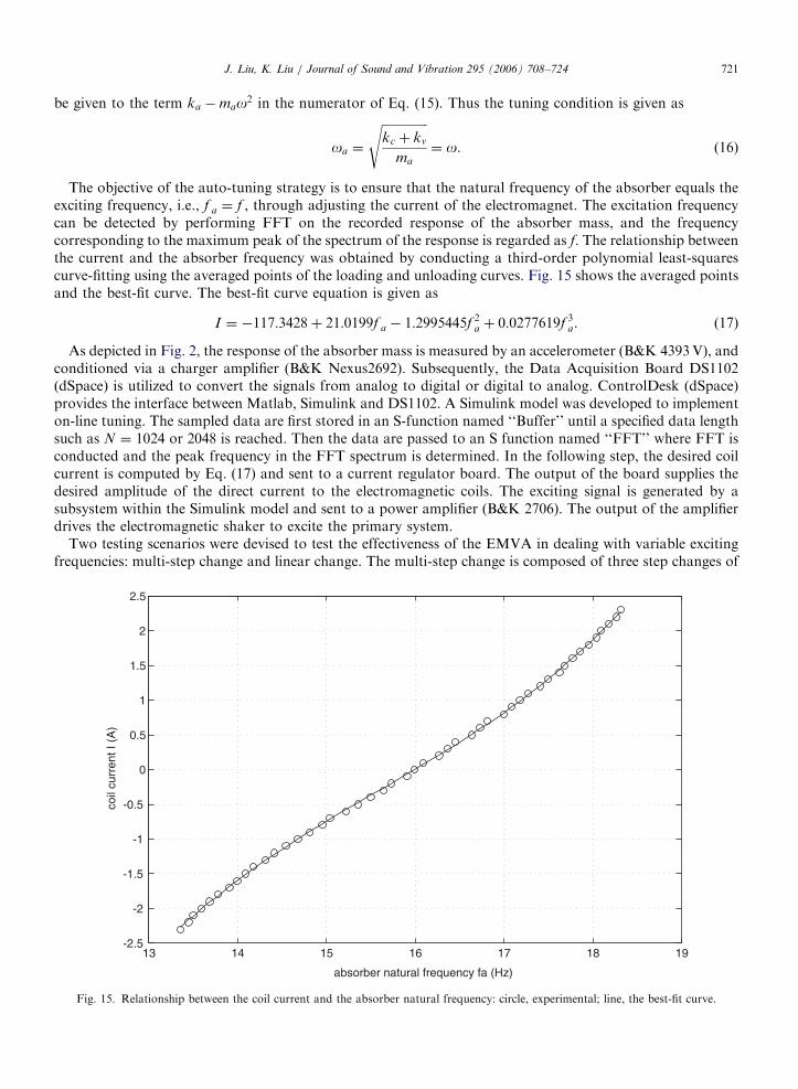
The objective of the auto-tuning strategy is to ensure that the natural frequency of the absorber equals theexciting frequency, i.e., f a ¼ f , through adjusting the current of the electromagnet. The excitation frequencycan be detected by performing FFT on the recorded response of the absorber mass, and the frequencycorresponding to the maximum peak of the spectrum of the response is regarded as f. The relationship betweenthe current and the absorber frequency was obtained by conducting a third-order polynomial least-squarescurve-fitting using the averaged points of the loading and unloading curves. Fig. 15 shows the averaged pointsand the best-fit curve. The best-fit curve equation is given as
I ¼ �117:3428þ 21:0199f a � 1:2995445f 2a þ 0:0277619f 3
a. (17)
As depicted in Fig. 2, the response of the absorber mass is measured by an accelerometer (B&K 4393V), andconditioned via a charger amplifier (B&K Nexus2692). Subsequently, the Data Acquisition Board DS1102(dSpace) is utilized to convert the signals from analog to digital or digital to analog. ControlDesk (dSpace)provides the interface between Matlab, Simulink and DS1102. A Simulink model was developed to implementon-line tuning. The sampled data are first stored in an S-function named ‘‘Buffer’’ until a specified data lengthsuch as N ¼ 1024 or 2048 is reached. Then the data are passed to an S function named ‘‘FFT’’ where FFT isconducted and the peak frequency in the FFT spectrum is determined. In the following step, the desired coilcurrent is computed by Eq. (17) and sent to a current regulator board. The output of the board supplies thedesired amplitude of the direct current to the electromagnetic coils. The exciting signal is generated by asubsystem within the Simulink model and sent to a power amplifier (B&K 2706). The output of the amplifierdrives the electromagnetic shaker to excite the primary system.
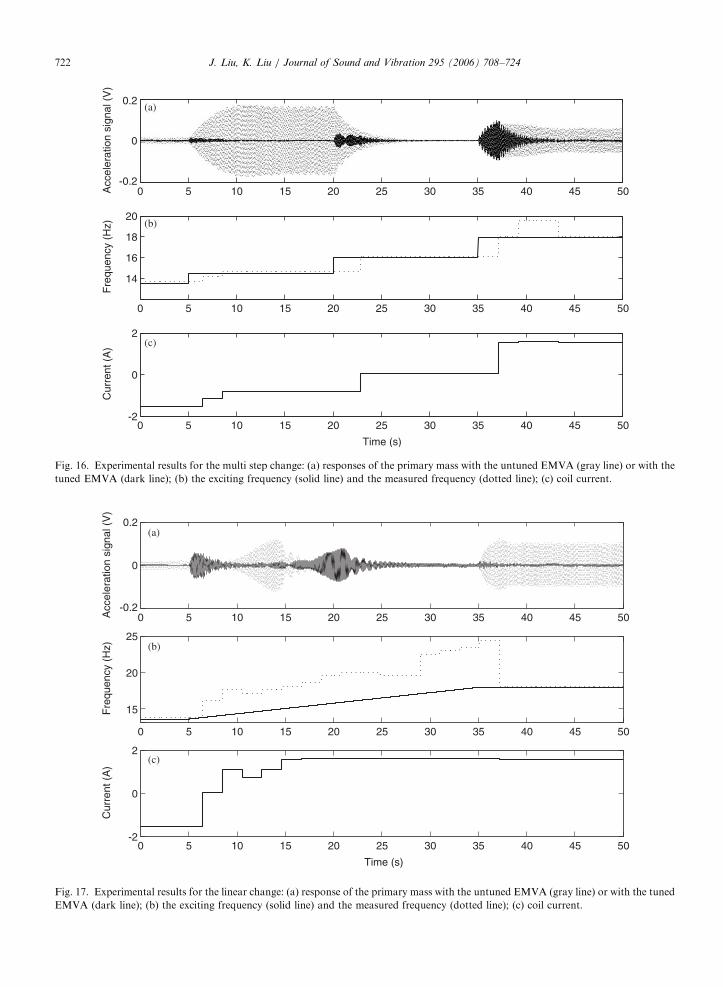
Two testing scenarios were devised to test the effectiveness of the EMVA in dealing with variable excitingfrequencies: multi-step change and linear change. The multi-step change is composed of three step changes of
13 14 15 16 17 18 19-2.5
-2
-1.5
-1
-0.5
0
0.5
1
1.5
2
2.5
absorber natural frequency fa (Hz)
coil
curr
ent I
(A
)
Fig. 15. Relationship between the coil current and the absorber natural frequency: circle, experimental; line, the best-fit curve.
ARTICLE IN PRESS
0 5 10 15 20 25 30 35 40 45 50 -0.2
0
0.2A
ccel
erat
ion
sign
al (
V)
0 5 10 15 20 25 30 35 40 45 50
14
16
18
20
Fre
quen
cy (
Hz)
0 5 10 15 20 25 30 35 40 45 50 -2
0
2
Time (s)
Cur
rent
(A
)(a)
(c)
(b)
Fig. 16. Experimental results for the multi step change: (a) responses of the primary mass with the untuned EMVA (gray line) or with the
tuned EMVA (dark line); (b) the exciting frequency (solid line) and the measured frequency (dotted line); (c) coil current.
0 5 10 15 20 25 30 35 40 45 50 -0.2
0
0.2
Acc
eler
atio
n si
gnal
(V
)
0 5 10 15 20 25 30 35 40 45 50
15
20
25
Fre
quen
cy (
Hz)
0 5 10 15 20 25 30 35 40 45 50-2
0
2
Time (s)
Cur
rent
(A
)
(a)
(b)
(c)
Fig. 17. Experimental results for the linear change: (a) response of the primary mass with the untuned EMVA (gray line) or with the tuned
EMVA (dark line); (b) the exciting frequency (solid line) and the measured frequency (dotted line); (c) coil current.
J. Liu, K. Liu / Journal of Sound and Vibration 295 (2006) 708–724722

ARTICLE IN PRESSJ. Liu, K. Liu / Journal of Sound and Vibration 295 (2006) 708–724 723
the exciting frequency. For the period of to5 s, the exciting frequency was 13.5Hz. At t ¼ 5 s, the excitingfrequency was suddenly changed to 14.5Hz. At t ¼ 20 s, it was changed to 16.0Hz. At t ¼ 35 s, it was changedto 17.9Hz. Fig. 16 shows the experimental results. When the EMVA was not tuned, the absorber frequencywas 16.0Hz. The first step change brought the system into resonance and the response was increasedsignificantly. The second step change resulted in the anti-resonance and the response was decreased. The thirdstep change once again forced the system into resonance and the response saw another surge. When the auto-tuning control was activated, the EMVA was capable of adjusting its stiffness such that vibration of theprimary mass was promptly suppressed at each stage. As the data length used was N ¼ 2048, the reaction timefor tuning was 2.048 s. It should be noted that the reaction time is solely dependent on the tuning algorithm,while for those motor-driven devices [1–5] extra time is needed for the desired stiffness to be reached. For thelinear change, the exciting frequency was varied linearly from 13.5 to 17.9Hz. Fig. 17 shows the results. It isnoted that the tuning algorithm based on FFT failed to follow the variation of the exciting frequency. Whenthe exciting frequency was continuously changed, the transient responses were excited out such that theresponse was dominated by a component associated with one of the natural frequencies. The peak frequencyin the FFT spectrum corresponded to the natural frequency instead of the exciting frequency. Such alimitation of the FFT-based algorithm was addressed in Ref. [5].
5. Conclusion
An electromagnetic vibration absorber (EMVA) has been developed. By varying the current to theelectromagnet, the absorber stiffness can be on-line adjusted; as a result, it can cope with a harmonicexcitation with a variable frequency. A stiffness characterization has been presented. The fundamental theoryof electromagnetism has been employed to establish the analytical relation for the variable magnetic stiffness.The analytical relation has been validated experimentally. The effectiveness of the electromagnetic vibrationabsorber has been tested. The experiment has shown that the EMVA is capable of adjusting its frequency suchthat the tuning condition is satisfied in the event of variation of the exciting frequency. The main advantagesof the proposed device lie in its rapid reaction and motionless adjustment. The analytical approachesemployed in this study are useful for further optimization of the device and for the design of any new devicesinvolved in similar applications of electromagnetism.
Several aspects deserve further discussion. The EMVA is capable of adjusting its stiffness instantaneously.A choice of switching time may affect the transients. It is well known that for free response of a simplespring–mass system, if the spring stiffness is changed from a low value to a high value at a zero velocity andnon-zero displacement, a large transient will be induced. However, the present system is a damped 2 dof one,subjected to an external excitation: the relationship between the transients and a switching time is morecomplicated than that for an undamped 1 dof system. In the experiment, no significant transients wereobserved when different switching times were tried. As well, the main concern of the study is suppression ofthe steady-state response. The transient responses will die out as the system possesses a certain degree ofdamping. Minimization of energy consumption remains for further study. Limited by the budget available, thepresent design is not an optimum one. It is expected that with an improvement of material selection andfabrication, the device can be made more efficient. As the EMVA has no mechanical drive system, it can easilybe miniaturized. This feature may be explored in micro-electro-mechanical systems (MEMS) devices.
Acknowledgments
The authors would like to express their gratitude to the National Science and Engineering Research Councilof Canada for financial support. The authors would also like to thank Mr. K. Batia for his help in thefabrication of the experimental apparatus.
References
[1] M.A. Franchek, M.W. Ryan, R.J. Bernhard, Adaptive passive vibration control, Journal of Sound and Vibration 189 (1995) 565–585.

ARTICLE IN PRESSJ. Liu, K. Liu / Journal of Sound and Vibration 295 (2006) 708–724724
[2] C. Buhr, M.A. Franchek, R.J. Bernhard, Non-collocated adaptive-passive vibration control, Journal of Sound and Vibration 206
(1997) 371–398.
[3] K. Nagaya, A. Kurusu, S. Ikai, Y. Shitani, Vibration control of a structure by using a tunable absorber and an optimal vibration
absorber under auto-tuning control, Journal of Sound and Vibration 228 (1999) 773–792.
[4] N. Varadarajan and S. Nagarajaiah, Response control of building with variable stiffness tuned mass damper using empirical mode
decomposition and Hilbert transform algorithm, 16th ASCE Engineering Mechanics Conference, July 2003, Seattle.
[5] K. Liu, L. Liao, J. Liu, Comparison of two auto-tuning methods for a variable stiffness vibration absorber, The Transactions of
Canadian Society for Mechanical Engineering 29 (2005) 81–96.
[6] W.N. Patten, R.L. Sack, Q. He, Controlled semiactive hydraulic vibration absorber for bridges, Journal of Structural Engineering 122
(1996) 187–192.
[7] M.D. Symans, M.C. Constantinou, Seismic testing of a building structure with a semi-active fluid damper control system, Earthquake
Engineering and Structural Dynamics 26 (1997) 759–777.
[8] P. Dupont, P. Kasturi, A. Stokes, Semi-active control of friction dampers, Journal of Sound and Vibration 202 (1997) 203–218.
[9] L.Y. Lu, Semi-active modal control seismic structures with variable friction dampers, Engineering Structures 26 (2004) 437–454.
[10] S.B. Choi, H.K. Lee, E.G. Chang, Field test results of a semi-active ER suspension system associated with skyhook controller,
Mechatronics 11 (2001) 345–353.
[11] A. Milecki, Investigation and control of magneto-rehological fluid dampers, International Journal of Machine Tools & Manufacture 41
(2001) 379–391.
[12] B. Erkus, M. Abe, Y. Fujino, Investigation of semi-active control for seismic protection of elevated highway bridges, Engineering
Structures 24 (2002) 281–293.
[13] T. Mizuno, K. Araki, Control system design of a dynamic vibration absorber with an electromagnetic servomechanism, Mechanical
Systems and Signal Processing 7 (1993) 293–306.
[14] M.S. Trimboli, R. Wimmel, E. Breitbach, A quasi-active approach to vibration isolation using magnetic springs, SPIE 2193 (1994)
73–83.
[15] Y. Matsuzaki, T. Ikeda, A. Nae, T. Sasaki, Electromagnetic forces for a new vibration control system: experimental verification,
Smart Materials and Structures 9 (2000) 127–131.
[16] C.C. Chen, M.K. Yeh, Parametric instability of a beam under electromagnetic excitation, Journal of Sound and Vibration 240 (2001)
747–764.
[17] S. Yashita and K. Seto, Vibration and noise control using dual dynamic absorbers with magnetic damping, Proceedings of The Third
International ISEM Symposium on the Application of Electromagnetic Forces, Sendai, 1992.
[18] D. Kienholz, S. Pendleton, Demonstration of solar array vibration suppression, SPIE 2193 (1994) 59–72.
[19] K. Liu, J. Liu, L. Liao, Application of a tunable electromagnetic damper in suppression of structural vibration, The Transactions of
the Canadian Society for Mechanical Engineering, February 2006 (in press).
[20] D.J. Craik, Magnetism: Principles and Applications, Wiley, Chichester, New York, 1995.
[21] H.H. Woodson, J.R. Melcher, Electromechanical Dynamics—part I: Discrete Systems, Wiley, New York, 1968.
[22] J. Liu, Design and Implementation of a Tunable Vibration Absorber and a Time-Delayed Vibration Absorber, MSc Thesis,
Lakehead University, Canada, 2005.