a variable stiffness gripper with antagonistic magnetic ...roboticsproceedings.org/rss14/p53.pdf ·...
TRANSCRIPT
A Variable Stiffness Gripper with AntagonisticMagnetic Springs for Enhancing Manipulation
Amirhossein H. Memar and Ehsan T. EsfahaniDepartment of Mechanical and Aerospace Engineering, University at Buffalo
Email: <ahajiagh, ehsanesf>@buffalo.edu
Abstract—Robot grasping of objects based on variable stiffnessactuation not only improves the safety and robustness of thegrasp but also enhances dynamic manipulation. In this paper,we present the design aspects of a variable stiffness gripperand demonstrate how the controllable compliance of the fingerscan improve the performance in dynamic manipulation taskssuch as hammering/hitting. The proposed gripper consists of twoparallel fingers and repulsive magnets are used as the nonlinearsprings between gripper actuators and fingers. The positionand force-stiffness characteristics of the fingers are adjustedsimultaneously, by controlling the air-gaps between magnets.Finally, the application of the gripper in a nail hammering task isstudied as an example of dynamic manipulation. For this purpose,an optimal stiffness control problem is solved to maximize theimpact force of the hammering task through maximizing thekinetic energy of the grasped object at the hitting instance.Despite the simplicity of the design, experimental results indicatethe effectiveness of the gripper for dynamic manipulation.
I. INTRODUCTION
In the past few years, there has been a growing interestin the development of Variable Stiffness Actuators (VSAs)as an alternative to conventional stiff joints for robot arms.Various mechanisms have been proposed to mechanicallyadjust the joint stiffness using compliant elements such assprings between the load and actuators [1]. Based on the taskrequirements, the stiffness of a VSA can be either increased,if the positioning accuracy is required, or decreased for acompliant interaction.
Generally, the inherent compliance and energy storage ca-pability of VSAs offers two main advantages: (i) Contrary tostiff joints, the elastic elements of VSAs act as a low-passfilter by absorbing the impact energy and preventing seriousdamages to the robot/environment [2]. This characteristic canimprove human safety in physical human-robot interactions;(ii) Task performance in fast and highly dynamic motions canbe improved by exploiting the natural dynamics and energystorage capability of the elastic elements [3].
Although considerable research has been devoted to thedesign of VSAs in the form of rotary joints, yet less attentionhas been paid to the robot grippers with adjustable compliantactuation. In fact, the development of fully VSA-based armswith multiple degrees of freedom (DoF) requires an extra ac-tuator at each joint which ultimately increases the complexity,size and the weight of the system [4]. Therefore, the designof variable stiffness grippers is a potential solution to achievesome of the key features of a fully VSA-based arm at a lowercost and complexity. By equipping conventional stiff arms with
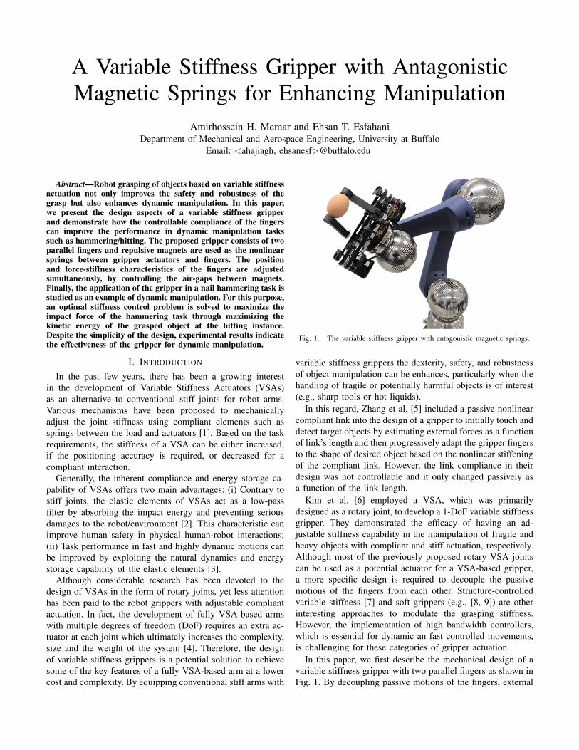
Fig. 1. The variable stiffness gripper with antagonistic magnetic springs.
variable stiffness grippers the dexterity, safety, and robustnessof object manipulation can be enhances, particularly when thehandling of fragile or potentially harmful objects is of interest(e.g., sharp tools or hot liquids).
In this regard, Zhang et al. [5] included a passive nonlinearcompliant link into the design of a gripper to initially touch anddetect target objects by estimating external forces as a functionof link’s length and then progressively adapt the gripper fingersto the shape of desired object based on the nonlinear stiffeningof the compliant link. However, the link compliance in theirdesign was not controllable and it only changed passively asa function of the link length.
Kim et al. [6] employed a VSA, which was primarilydesigned as a rotary joint, to develop a 1-DoF variable stiffnessgripper. They demonstrated the efficacy of having an ad-justable stiffness capability in the manipulation of fragile andheavy objects with compliant and stiff actuation, respectively.Although most of the previously proposed rotary VSA jointscan be used as a potential actuator for a VSA-based gripper,a more specific design is required to decouple the passivemotions of the fingers from each other. Structure-controlledvariable stiffness [7] and soft grippers (e.g., [8, 9]) are otherinteresting approaches to modulate the grasping stiffness.However, the implementation of high bandwidth controllers,which is essential for dynamic an fast controlled movements,is challenging for these categories of gripper actuation.
In this paper, we first describe the mechanical design of avariable stiffness gripper with two parallel fingers as shown inFig. 1. By decoupling passive motions of the fingers, external
forces acting on each finger can be estimated separately. Fur-thermore, when an object is grasped, the simultaneous passivedeflection of the fingers in the direction of external forces canbe realized. This improves the safety and robustness of thegrasp, particularly during collisions with stiff environments[10]. The nonlinear compliant actuation, which is essential forantagonistic VSAs, is generated by using permanent magnetsin a repulsive configuration. Thanks to the non-contact forceinteraction between magnets, tolerance to misalignments andlow frictional hysteresis are obtained.
In addition to the design aspects, this paper presents theapplication of the proposed gripper for dynamic manipulation.The term dynamic manipulation refers to the methods whichexploit the natural dynamics of the grasped object, as a resultof arm movements, to improve the task performance [11]. Inother words, dynamic and quick motions of the robot armgive accelerations to the grasped object to perform tasks suchas ball juggling [12], hammering [13] and re-grasping [14].The energy storage capability, in addition to the controllablestiffness, empowers VSAs to realize dynamic tasks that requirereleasing a large amount of energy over a short period oftime. In these applications, it is desired to achieve a maximumkinetic energy (at a specific time or position) by releasing thestored potential energy in the elastic elements.
Garabini et al. [13, 15] studied the optimal control principlesof a 1-DoF rotary VSA during the execution of hitting tasksby maximizing the link velocity at a given final position/time.They showed that varying the stiffness during the executionof hitting tasks significantly improves the performance (finalvelocity of the link). Similarly, Braun et al. [16] utilizeda 2-DoF VSA arm and applied optimal control theory toexperimentally show the capability of VSAs to enhance ballthrowing by maximizing the projectile’s length.
In previous studies, VSAs are mostly designed and utilizedas rotary joints between the arm links. However, performingdynamic manipulation with a variable stiffness gripper im-poses extra constraints in terms of ensuring an appropriategrasp during arm motions. Furthermore, the dynamics ofthe grasped object is a function of not only the gripperactuators but also the end-effector motions. Thus, in this paper,we experimentally investigate the extent to which a variablestiffness gripper mounted on a conventional stiff arm can beused in dynamic manipulation. For this purpose, an optimalstiffness trajectory problem is formulated for a hammeringtask. The objective is to increase the impact force by max-imizing the hammer’s kinetic energy at the hitting instanceof a wind-up motion. The results of numerical simulationsand the hammering experiment are presented and discussedaccordingly.
II. MODEL OF THE PROPOSED GRIPPER
A. Design Concept
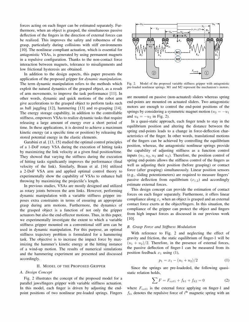
Fig. 2 illustrates the concept of the proposed model for aparallel jaws/fingers gripper with variable stiffness actuation.In this model, each finger is driven by adjusting the end-point positions of two nonlinear pre-loaded springs. Fingers
Fig. 2. Model of the proposed variable stiffness gripper with antagonisticpre-loaded nonlinear springs. M1 and M2 represent the mechanism’s motors.
are mounted on passive (non-actuated) sliders whereas springend-points are mounted on actuated sliders. Two antagonisticmotors are enough to control the end-point positions of thesprings by considering a symmetric magnet motion (u3 = −u1and u4 = −u2 in Fig. 2).
In a quasi-static approach, each finger tends to stay in theequilibrium position and altering the distance between thespring end-points leads to a change in force-deflection char-acteristics of the finger. In other words, translational motionsof the fingers can be achieved by controlling the equilibriumposition, whereas, the antagonistic nonlinear springs providethe capability of adjusting stiffness as a function controlinputs (u1, u2, u3 and u4). Therefore, the position control ofspring end-points allows the stiffness control of the fingers aswell as adjusting their position (before grasping) or contactforce (after grasping) simultaneously. Linear position sensors(e.g., sliding potentiometers) are required to measure fingers’passive deflection from equilibrium (x1,2) and accordinglyestimate external forces.
This design concept can provide the estimation of contactforces on each finger separately. Furthermore, it offers linearcompliance along xe when an object is grasped and an externalcontact force exerts at the object/fingers. In this situation, thecompliance of the gripper can protect the object and fingersfrom high impact forces as discussed in our previous work[10].
B. Grasp Force and Stiffness Modulation
With reference to Fig. 2 and neglecting the effect ofgravity and friction, the static equilibrium of finger-1 will be(u1 + u2)/2. Therefore, in the presence of external forces,the passive deflection of finger-1 can be measured from itsposition feedback x1 using (1),
p1 = x1 − (u1 + u2)/2 (1)
Since the springs are pre-loadeded, the following quasi-static relation holds,∑
F = Fext1 + fk1 + fk2 = 0 (2)
where Fext1 is the external force applying on finger-1 andfki denotes the repulsive force of ith magnetic spring with an
end-point position of ui with a model which will be presentedin (5). The directions of these forces and accordingly theirsigns in (2) can be determined based on the magnet locationswith respect to the finger. Therefore, for a given deflection ofp1, the force and stiffness can be estimated by the followingrelations,
Fext1(p1, u1, u2) = fk1 − fk2 (3)
K1(p1, u1, u2) =dFext1
dp1=dfk1dp1− dfk2dp1
(4)
where K1 is the finger stiffness as a function of its passivedeflection and control inputs. Due to the antagonistic design,force and stiffness can be simultaneously modulated althoughthey are not independent.
C. Mechanical Design
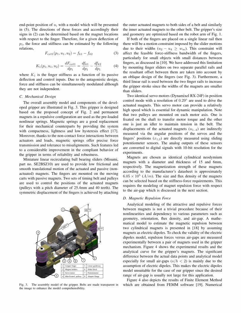
The overall assembly model and components of the devel-oped gripper are illustrated in Fig. 3. This gripper is designedbased on the proposed concept of Fig. 2 and permanentmagnets in a repulsive configuration are used as the pre-loadednonlinear springs. Magnetic springs are a good replacementfor their mechanical counterparts by providing the systemwith compactness, lightness and low hysteresis effect [17].Moreover, thanks to the non-contact force interactions betweenactuators and loads, magnetic springs offer precise forcetransmission and tolerance to misalignments. Such features ledto a considerable improvement in the compliant behavior ofthe gripper in terms of reliability and robustness.
Miniature linear recirculating ball bearing sliders (Misumi,part no. SE2BSZ10) are used to provide low frictional andsmooth translational motion of the actuated and passive (non-actuated) magnets. The fingers are mounted on the movingcarts with passive magnets. Two sets of timing belt and pulleysare used to control the positions of the actuated magnets(pulleys with a pitch diameter of 25.4mm and 40 teeth). Thesymmetric displacement of the fingers is achieved by attaching
2
1
8 75
3
4
85mm
65mm
1 Gripper finger 5 Linear guideway
2 Magnet holders 6 Slider block
3 Servo motor 7 Potentiometer
4 Idler/fixated pulleys 8 Adapter flange
6
Fig. 3. The assembly model of the gripper. Belts are made transparent inthe image to enhance the model comprehensibility.
the outer actuated magnets to both sides of a belt and similarlythe inner actuated magnets to the other belt. The gripper’s sizeand geometry are optimized based on the robot arm of Fig. 1.
If both of the fingers are placed on a single linear rail thenthere will be a motion constraint imposed by the slider motionsdue to their widths (u2 − u4 ≥ wm). This constraint willaffect the feasible force-stiffness bandwidth of the fingers,particularly for small objects with small distances betweenfingers, as discussed in [10]. We have addressed this limitationby mounting finger sliders on two separate parallel rails andthe resultant offset between them are taken into account byan oblique design of the fingers (see Fig. 3). Furthermore, athird linear rail is used between the two finger rails to increasethe gripper stroke since the widths of the magnets are smallerthan sliders.
Two identical servo motors (Dynamixel RX-24F) in positioncontrol mode with a resolution of 0.29◦ are used to drive theactuated magnets. This servo motor can provide a relativelyhigh speed which is essential for dynamic manipulation. Notethat two pulleys are mounted on each motor axis. One isfixated on the shaft to transfer motor torque and the otherone is just an idler to maintain tension in the belt. Thedisplacements of the actuated magnets (u1..4) are indirectlymeasured via the angular positions of the servos and thefingers’ positions (x1,2) are directly measured using slidingpotentiometer sensors. The analog outputs of these sensorsare converted to digital signals with 10-bit resolution for theexperiments.
Magnets are chosen as identical cylindrical neodymiummagnets with a diameter and thickness of 15 and 6mm,respectively. The magnetization strength of these magnetsaccording to the manufacturer’s datasheet is approximately6.05 × 105 (A/m). The size and flux density of the magnetscan be selected based on the stiffness-force requirements. Thisrequires the modeling of magnet repulsion force with respectto the air-gap which is discussed in the next section.
D. Magnetic Repulsion Force
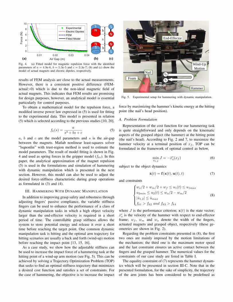
Analytical modeling of the attractive and repulsive forcesbetween magnets is not a trivial procedure because of theirnonlinearities and dependency to various parameters such asgeometry, orientation, flux density, and air-gap. A mathe-matical model to estimate the magnetic repulsion betweentwo cylindrical magnets is presented in [18] by assumingmagnets as electric dipoles. To check the validity of the electricdipoles model, repulsion forces versus air-gaps are measuredexperimentally between a pair of magnets used in the grippermechanism. Figure 4 shows the experimental results and theanalytical curve for the gripper’s magnets. The significantdifference between the actual data points and analytical modelespecially for small air-gaps (s/h < 2) is mainly due to theassumption of electric dipoles. This makes the electric dipolesmodel unsuitable for the case of our gripper since the desiredrange of air-gap is usually not large for this application.
Figure 4 also depicts the results of Finite Element Methodwhich are obtained from FEMM software [19]. Numerical
NS
NS
s
h
hN
N
(a) (b) (c)
Fig. 4. (a) Fitted model for magnetic repulsion force with the identifiedparameters of a = 4.9e-6, b = 5.3e-5 and c = 2.3e-7; (b) and (c) show themodel of actual magnets and electric dipoles, respectively.
results of FEM analysis are close to the actual measurements.However, there is a consistent positive difference (FEM-actual>0) which is due to the non-ideal magnetic field ofactual magnets. This indicates that FEM results are promisingfor design purposes, however, an analytical model is essentialparticularly for control purposes.
To obtain a mathematical model for the repulsion force, amodified inverse power law expressed in (5) is used for fittingto the experimental data. This model is presented in relation(5) which is selected according to the previous studies [10, 20].
fk(s) =a
s3 + bs+ c(5)
a, b and c are the model parameters and s is the air-gapbetween the magnets. Matlab nonlinear least-squares solver“lsqnonlin” with trust-region method is used to estimate themodel parameters. The result of model fitting is shown in Fig.4 and used as spring forces in the gripper model (fki). In thispaper, the analytical approximation of the magnet repulsion(5) is used in the formulations and simulation of hammeringwith dynamic manipulation which is presented in the nextsection. However, this model can also be used to adjust thedesired force-stiffness characteristic during grasp operationsas formulated in (3) and (4).
III. HAMMERING WITH DYNAMIC MANIPULATION
In addition to improving grasp safety and robustness throughadjusting fingers’ passive compliance, the variable stiffnessfingers can be used to enhance the performance of a class ofdynamic manipulation tasks in which a high object velocitylarger than the end-effector velocity is required in a shortperiod of time. The controllable grasp stiffness allows thesystem to store potential energy and release it over a shorttime before reaching the target point. One common dynamicmanipulation task is hitting and the optimal arm trajectory forhitting scenarios are usually a back and forth (wind-up) motionbefore reaching the impact point [13, 15, 16].
As a case study, we show how the adjustable stiffness canbe used to increase the impact force of a hammering task at thehitting point of a wind-up arm motion (see Fig. 5). This can beachieved by solving a Trajectory Optimization Problem (TOP)that seeks to find an optimal stiffness trajectory that minimizesa desired cost function and satisfies a set of constraints. Forthe case of hammering, the objective is to increase the impact
Foam
Hammer
Nail
Wind-Up
Motion
End-Effector
t0
tf
Fig. 5. Experimental setup for hammering with dynamic manipulation.
force by maximizing the hammer’s kinetic energy at the hittingpoint (the nail’s head position).
A. Problem Formulation
Representation of the cost function for our hammering taskis quite straightforward and only depends on the kinematicaspects of the grasped object (the hammer) at the hitting point(the nail’s head). According to Fig. 2 and 7, to maximize thehammer velocity at a terminal position of xf , TOP can beformulated in the framework of optimal control as below,
minu1,2
J = −xeo(xf ) (6)
subject to the object dynamics
x(t) = f(x(t),u(t), t) (7)
and constraintswo/2 + wm/2 + wf ≤ u1(t) ≤ u1max
u2min ≤ u2(t) ≤ wo/2− wm/2
|u1,2| ≤ umax
fk1 > fk2 and fk3 > fk4
(8)
where J is the performance criterion; x(t) is the state vector;xeo is the velocity of the hammer with respect to end-effectorframe; wf , wm and wo denote the width of the fingers,actuated magnets and grasped object, respectively (these ge-ometries are shown in Fig. 2).
Regarding the problem constraints presented in (8), the firsttwo ones are mainly imposed by the motion limitations ofthe mechanism; the third one is the maximum motor speedand the last constraint ensures an active contact between thefingers and the grasped hammer. The numerical values for theconstraints of our case study are listed in Table I.
The equality constraint of (7) represents the hammer dynam-ics which will be presented in section III-C. Note that in thepresented formulation, for the sake of simplicity, the trajectoryof the arm joints has been considered to be predefined as
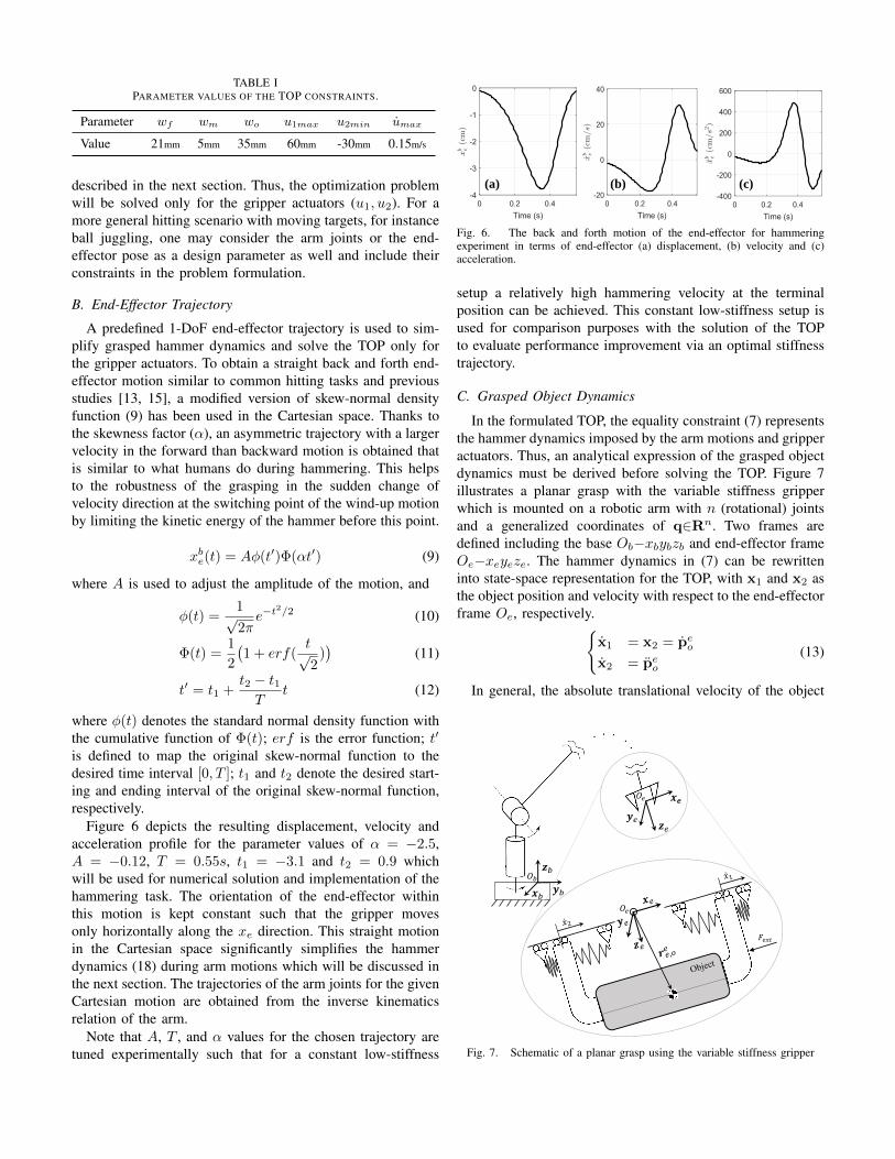
TABLE IPARAMETER VALUES OF THE TOP CONSTRAINTS.
Parameter wf wm wo u1max u2min umax
Value 21mm 5mm 35mm 60mm -30mm 0.15m/s
described in the next section. Thus, the optimization problemwill be solved only for the gripper actuators (u1, u2). For amore general hitting scenario with moving targets, for instanceball juggling, one may consider the arm joints or the end-effector pose as a design parameter as well and include theirconstraints in the problem formulation.
B. End-Effector Trajectory
A predefined 1-DoF end-effector trajectory is used to sim-plify grasped hammer dynamics and solve the TOP only forthe gripper actuators. To obtain a straight back and forth end-effector motion similar to common hitting tasks and previousstudies [13, 15], a modified version of skew-normal densityfunction (9) has been used in the Cartesian space. Thanks tothe skewness factor (α), an asymmetric trajectory with a largervelocity in the forward than backward motion is obtained thatis similar to what humans do during hammering. This helpsto the robustness of the grasping in the sudden change ofvelocity direction at the switching point of the wind-up motionby limiting the kinetic energy of the hammer before this point.
xbe(t) = Aφ(t′)Φ(αt′) (9)
where A is used to adjust the amplitude of the motion, and
φ(t) =1√2πe−t
2/2 (10)
Φ(t) =1
2
(1 + erf(
t√2
))
(11)
t′ = t1 +t2 − t1T
t (12)
where φ(t) denotes the standard normal density function withthe cumulative function of Φ(t); erf is the error function; t′
is defined to map the original skew-normal function to thedesired time interval [0, T ]; t1 and t2 denote the desired start-ing and ending interval of the original skew-normal function,respectively.
Figure 6 depicts the resulting displacement, velocity andacceleration profile for the parameter values of α = −2.5,A = −0.12, T = 0.55s, t1 = −3.1 and t2 = 0.9 whichwill be used for numerical solution and implementation of thehammering task. The orientation of the end-effector withinthis motion is kept constant such that the gripper movesonly horizontally along the xe direction. This straight motionin the Cartesian space significantly simplifies the hammerdynamics (18) during arm motions which will be discussed inthe next section. The trajectories of the arm joints for the givenCartesian motion are obtained from the inverse kinematicsrelation of the arm.
Note that A, T , and α values for the chosen trajectory aretuned experimentally such that for a constant low-stiffness
(a) (b) (c)
Fig. 6. The back and forth motion of the end-effector for hammeringexperiment in terms of end-effector (a) displacement, (b) velocity and (c)acceleration.
setup a relatively high hammering velocity at the terminalposition can be achieved. This constant low-stiffness setup isused for comparison purposes with the solution of the TOPto evaluate performance improvement via an optimal stiffnesstrajectory.
C. Grasped Object Dynamics
In the formulated TOP, the equality constraint (7) representsthe hammer dynamics imposed by the arm motions and gripperactuators. Thus, an analytical expression of the grasped objectdynamics must be derived before solving the TOP. Figure 7illustrates a planar grasp with the variable stiffness gripperwhich is mounted on a robotic arm with n (rotational) jointsand a generalized coordinates of q∈Rn. Two frames aredefined including the base Ob−xbybzb and end-effector frameOe−xeyeze. The hammer dynamics in (7) can be rewritteninto state-space representation for the TOP, with x1 and x2 asthe object position and velocity with respect to the end-effectorframe Oe, respectively.{
x1 = x2 = peo
x2 = peo
(13)
In general, the absolute translational velocity of the object
𝒚𝑏𝒙𝑏
𝒛𝑏𝑂𝑏
𝑂𝑒
𝐹𝑒𝑥𝑡
𝒛𝑒𝒚𝑒
𝒙𝒆
𝑂𝑒
Fig. 7. Schematic of a planar grasp using the variable stiffness gripper
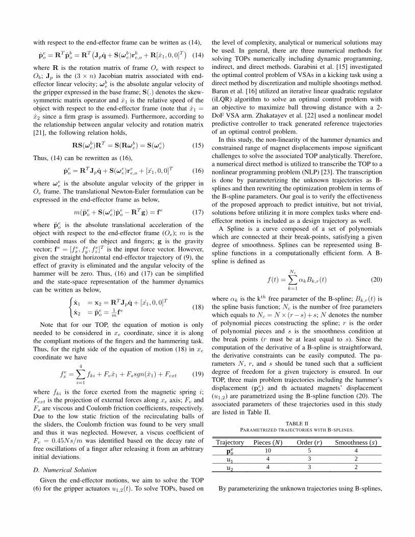
with respect to the end-effector frame can be written as (14),
peo = RT pb
o = RT(Jpq + S(ωb
e)rbe,o + R[x1, 0, 0]T
)(14)
where R is the rotation matrix of frame Oe with respect toOb; Jp is the (3 × n) Jacobian matrix associated with end-effector linear velocity; ωb
e is the absolute angular velocity ofthe gripper expressed in the base frame; S(.) denotes the skew-symmetric matrix operator and x1 is the relative speed of theobject with respect to the end-effector frame (note that x1 =x2 since a firm grasp is assumed). Furthermore, according tothe relationship between angular velocity and rotation matrix[21], the following relation holds,
RS(ωbe)R
T = S(Rωbe) = S(ωe
e) (15)
Thus, (14) can be rewritten as (16),
peo = RTJpq + S(ωe
e)ree,o + [x1, 0, 0]T (16)
where ωee is the absolute angular velocity of the gripper in
Oe frame. The translational Newton-Euler formulation can beexpressed in the end-effector frame as below,
m(peo + S(ωe
e)peo −RTg) = fe (17)
where peo is the absolute translational acceleration of the
object with respect to the end-effector frame (Oe); m is thecombined mass of the object and fingers; g is the gravityvector; fe = [fex , f
ey , f
ez ]T is the input force vector. However,
given the straight horizontal end-effector trajectory of (9), theeffect of gravity is eliminated and the angular velocity of thehammer will be zero. Thus, (16) and (17) can be simplifiedand the state-space representation of the hammer dynamicscan be written as below,{
x1 = x2 = RTJpq + [x1, 0, 0]T
x2 = peo = 1
m fe(18)
Note that for our TOP, the equation of motion is onlyneeded to be considered in xe coordinate, since it is alongthe compliant motions of the fingers and the hammering task.Thus, for the right side of the equation of motion (18) in xecoordinate we have
fex =
4∑i=1
fki + Fvx1 + Fssgn(x1) + Fext (19)
where fki is the force exerted from the magnetic spring i;Fext is the projection of external forces along xe axis; Fv andFs are viscous and Coulomb friction coefficients, respectively.Due to the low static friction of the recirculating balls ofthe sliders, the Coulomb friction was found to be very smalland thus it was neglected. However, a viscus coefficient ofFv = 0.45Ns/m was identified based on the decay rate offree oscillations of a finger after releasing it from an arbitraryinitial deviations.
D. Numerical Solution
Given the end-effector motions, we aim to solve the TOP(6) for the gripper actuators u1,2(t). To solve TOPs, based on
the level of complexity, analytical or numerical solutions maybe used. In general, there are three numerical methods forsolving TOPs numerically including dynamic programming,indirect, and direct methods. Garabini et al. [15] investigatedthe optimal control problem of VSAs in a kicking task using adirect method by discretization and multiple shootings method.Barun et al. [16] utilized an iterative linear quadratic regulator(iLQR) algorithm to solve an optimal control problem withan objective to maximize ball throwing distance with a 2-DoF VSA arm. Zhakatayev et al. [22] used a nonlinear modelpredictive controller to track generated reference trajectoriesof an optimal control problem.
In this study, the non-linearity of the hammer dynamics andconstrained range of magnet displacements impose significantchallenges to solve the associated TOP analytically. Therefore,a numerical direct method is utilized to transcribe the TOP to anonlinear programming problem (NLP) [23]. The transcriptionis done by parameterizing the unknown trajectories as B-splines and then rewriting the optimization problem in terms ofthe B-spline parameters. Our goal is to verify the effectivenessof the proposed approach to predict intuitive, but not trivial,solutions before utilizing it in more complex tasks where end-effector motion is included as a design trajectory as well.
A Spline is a curve composed of a set of polynomialswhich are connected at their break-points, satisfying a givendegree of smoothness. Splines can be represented using B-spline functions in a computationally efficient form. A B-spline is defined as
f(t) =
Nc∑k=1
αkBk,r(t) (20)
where αk is the kth free parameter of the B-spline; Bk,r(t) isthe spline basis function; Nc is the number of free parameterswhich equals to Nc = N × (r−s)+s; N denotes the numberof polynomial pieces constructing the spline; r is the orderof polynomial pieces and s is the smoothness condition atthe break points (r must be at least equal to s). Since thecomputation of the derivative of a B-spline is straightforward,the derivative constraints can be easily computed. The pa-rameters N , r, and s should be tuned such that a sufficientdegree of freedom for a given trajectory is ensured. In ourTOP, three main problem trajectories including the hammer’sdisplacement (pe
o) and th actuated magnets’ displacement(u1,2) are parametrized using the B-spline function (20). Theassociated parameters of these trajectories used in this studyare listed in Table II.
TABLE IIPARAMETRIZED TRAJECTORIES WITH B-SPLINES.
Trajectory Pieces (𝑁) Order (𝑟) Smoothness (𝑠)
𝐩𝑜𝑒 10 5 4
𝑢1 4 3 2
𝑢2 4 3 2
By parameterizing the unknown trajectories using B-splines,
𝑢1−𝑢2 (cm
)
𝑥 𝑒𝑏 (cm
s2
) 𝑥 𝑒𝑏 (cm
𝑠
)
9
8
7
6
5
6
4
2
0
-2
𝑢1,𝑢
2 (cm
)
time (s)
time (s)
hammer end effector
𝑢1
𝑢2
𝑢1−𝑢2
𝑥 (cm
)
stiff compliant stiff compliant
𝐚) 𝐛)
stiff compliant stiff compliant
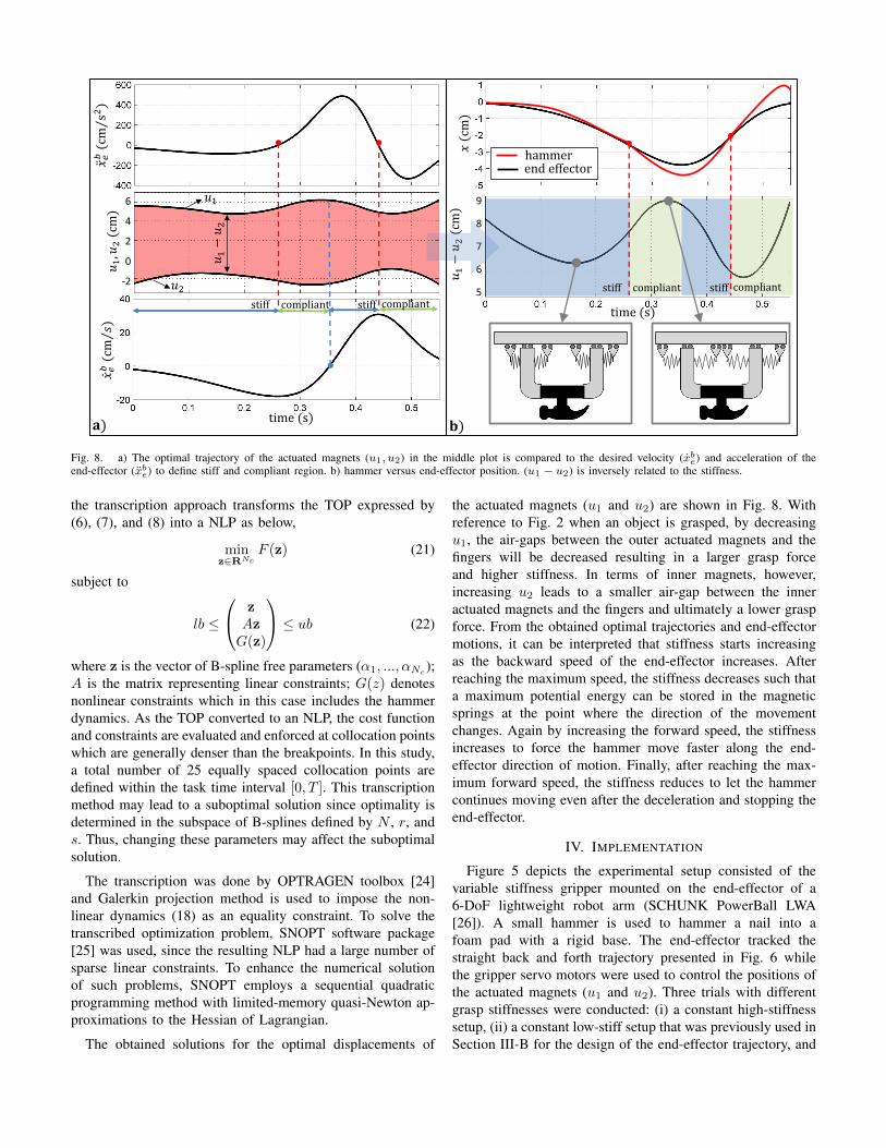
Fig. 8. a) The optimal trajectory of the actuated magnets (u1, u2) in the middle plot is compared to the desired velocity (xbe) and acceleration of the
end-effector (xbe) to define stiff and compliant region. b) hammer versus end-effector position. (u1 − u2) is inversely related to the stiffness.
the transcription approach transforms the TOP expressed by(6), (7), and (8) into a NLP as below,
minz∈RNc
F (z) (21)
subject to
lb ≤
zAzG(z)
≤ ub (22)
where z is the vector of B-spline free parameters (α1, ..., αNc);
A is the matrix representing linear constraints; G(z) denotesnonlinear constraints which in this case includes the hammerdynamics. As the TOP converted to an NLP, the cost functionand constraints are evaluated and enforced at collocation pointswhich are generally denser than the breakpoints. In this study,a total number of 25 equally spaced collocation points aredefined within the task time interval [0, T ]. This transcriptionmethod may lead to a suboptimal solution since optimality isdetermined in the subspace of B-splines defined by N , r, ands. Thus, changing these parameters may affect the suboptimalsolution.
The transcription was done by OPTRAGEN toolbox [24]and Galerkin projection method is used to impose the non-linear dynamics (18) as an equality constraint. To solve thetranscribed optimization problem, SNOPT software package[25] was used, since the resulting NLP had a large number ofsparse linear constraints. To enhance the numerical solutionof such problems, SNOPT employs a sequential quadraticprogramming method with limited-memory quasi-Newton ap-proximations to the Hessian of Lagrangian.
The obtained solutions for the optimal displacements of
the actuated magnets (u1 and u2) are shown in Fig. 8. Withreference to Fig. 2 when an object is grasped, by decreasingu1, the air-gaps between the outer actuated magnets and thefingers will be decreased resulting in a larger grasp forceand higher stiffness. In terms of inner magnets, however,increasing u2 leads to a smaller air-gap between the inneractuated magnets and the fingers and ultimately a lower graspforce. From the obtained optimal trajectories and end-effectormotions, it can be interpreted that stiffness starts increasingas the backward speed of the end-effector increases. Afterreaching the maximum speed, the stiffness decreases such thata maximum potential energy can be stored in the magneticsprings at the point where the direction of the movementchanges. Again by increasing the forward speed, the stiffnessincreases to force the hammer move faster along the end-effector direction of motion. Finally, after reaching the max-imum forward speed, the stiffness reduces to let the hammercontinues moving even after the deceleration and stopping theend-effector.
IV. IMPLEMENTATION
Figure 5 depicts the experimental setup consisted of thevariable stiffness gripper mounted on the end-effector of a6-DoF lightweight robot arm (SCHUNK PowerBall LWA[26]). A small hammer is used to hammer a nail into afoam pad with a rigid base. The end-effector tracked thestraight back and forth trajectory presented in Fig. 6 whilethe gripper servo motors were used to control the positions ofthe actuated magnets (u1 and u2). Three trials with differentgrasp stiffnesses were conducted: (i) a constant high-stiffnesssetup, (ii) a constant low-stiff setup that was previously used inSection III-B for the design of the end-effector trajectory, and
(𝑢1−𝑢2)
t0 t1 t2 t3 t4
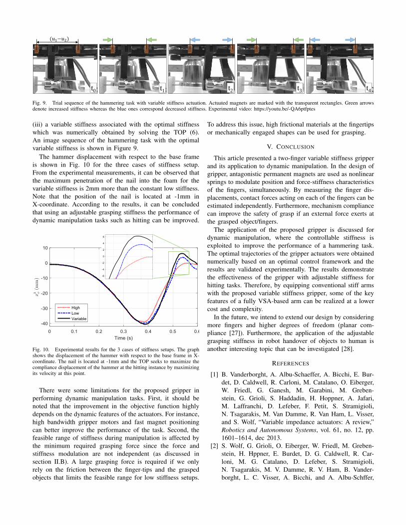
Fig. 9. Trial sequence of the hammering task with variable stiffness actuation. Actuated magnets are marked with the transparent rectangles. Green arrowsdenote increased stiffness whereas the blue ones correspond decreased stiffness. Experimental video: https://youtu.be/-QA6ptfptes
(iii) a variable stiffness associated with the optimal stiffnesswhich was numerically obtained by solving the TOP (6).An image sequence of the hammering task with the optimalvariable stiffness is shown in Figure 9.
The hammer displacement with respect to the base frameis shown in Fig. 10 for the three cases of stiffness setup.From the experimental measurements, it can be observed thatthe maximum penetration of the nail into the foam for thevariable stiffness is 2mm more than the constant low stiffness.Note that the position of the nail is located at -1mm inX-coordinate. According to the results, it can be concludedthat using an adjustable grasping stiffness the performance ofdynamic manipulation tasks such as hitting can be improved.
Fig. 10. Experimental results for the 3 cases of stiffness setups. The graphshows the displacement of the hammer with respect to the base frame in X-coordinate. The nail is located at -1mm and the TOP seeks to maximize thecompliance displacement of the hammer at the hitting instance by maximizingits velocity at this point.
There were some limitations for the proposed gripper inperforming dynamic manipulation tasks. First, it should benoted that the improvement in the objective function highlydepends on the dynamic features of the actuators. For instance,high bandwidth gripper motors and fast magnet positioningcan better improve the performance of the task. Second, thefeasible range of stiffness during manipulation is affected bythe minimum required grasping force since the force andstiffness modulation are not independent (as discussed insection II.B). A large grasping force is required if we onlyrely on the friction between the finger-tips and the graspedobjects that limits the feasible range for low stiffness setups.
To address this issue, high frictional materials at the fingertipsor mechanically engaged shapes can be used for grasping.
V. CONCLUSION
This article presented a two-finger variable stiffness gripperand its application to dynamic manipulation. In the design ofgripper, antagonistic permanent magnets are used as nonlinearsprings to modulate position and force-stiffness characteristicsof the fingers, simultaneously. By measuring the finger dis-placements, contact forces acting on each of the fingers can beestimated independently. Furthermore, mechanism compliancecan improve the safety of grasp if an external force exerts atthe grasped object/fingers.
The application of the proposed gripper is discussed fordynamic manipulation, where the controllable stiffness isexploited to improve the performance of a hammering task.The optimal trajectories of the gripper actuators were obtainednumerically based on an optimal control framework and theresults are validated experimentally. The results demonstratethe effectiveness of the gripper with adjustable stiffness forhitting tasks. Therefore, by equipping conventional stiff armswith the proposed variable stiffness gripper, some of the keyfeatures of a fully VSA-based arm can be realized at a lowercost and complexity.
In the future, we intend to extend our design by consideringmore fingers and higher degrees of freedom (planar com-pliance [27]). Furthermore, the application of the adjustablegrasping stiffness in robot handover of objects to human isanother interesting topic that can be investigated [28].
REFERENCES
[1] B. Vanderborght, A. Albu-Schaeffer, A. Bicchi, E. Bur-det, D. Caldwell, R. Carloni, M. Catalano, O. Eiberger,W. Friedl, G. Ganesh, M. Garabini, M. Greben-stein, G. Grioli, S. Haddadin, H. Hoppner, A. Jafari,M. Laffranchi, D. Lefeber, F. Petit, S. Stramigioli,N. Tsagarakis, M. Van Damme, R. Van Ham, L. Visser,and S. Wolf, “Variable impedance actuators: A review,”Robotics and Autonomous Systems, vol. 61, no. 12, pp.1601–1614, dec 2013.
[2] S. Wolf, G. Grioli, O. Eiberger, W. Friedl, M. Greben-stein, H. Hppner, E. Burdet, D. G. Caldwell, R. Car-loni, M. G. Catalano, D. Lefeber, S. Stramigioli,N. Tsagarakis, M. V. Damme, R. V. Ham, B. Vander-borght, L. C. Visser, A. Bicchi, and A. Albu-Schffer,
“Variable stiffness actuators: Review on design and com-ponents,” IEEE/ASME Transactions on Mechatronics,vol. 21, no. 5, pp. 2418–2430, Oct 2016.
[3] J. Nakanishi and S. Vijayakumar, “Exploiting passive dy-namics with variable stiffness actuation in robot brachia-tion,” Robotics: Science and Systems VIII, p. 305, 2013.
[4] N. G. Tsagarakis, I. Sardellitti, and D. G. Caldwell, “Anew variable stiffness actuator (compact-vsa): Design andmodelling,” in 2011 IEEE/RSJ International Conferenceon Intelligent Robots and Systems, Sept 2011, pp. 378–383.
[5] Z. Zhang, A. Rodriguez, and M. T. Mason, “A novelnonlinear compliant link on simple grippers,” in In-telligent Robots and Systems (IROS), 2015 IEEE/RSJInternational Conference on. IEEE, 2015, pp. 2923–2928.
[6] B.-S. Kim and J.-B. Song, “Object grasping using a1 DOF variable stiffness gripper actuated by a hybridvariable stiffness actuator,” in 2011 IEEE InternationalConference on Robotics and Automation. IEEE, may2011, pp. 4620–4625.
[7] X. Li, W. Chen, W. Lin, and K. H. Low, “A variablestiffness robotic gripper based on structure-controlledprinciple,” IEEE Transactions on Automation Scienceand Engineering, 2017.
[8] A. Firouzeh and J. Paik, “Grasp mode and compliancecontrol of an underactuated origami gripper using ad-justable stiffness joints,” IEEE/ASME Transactions onMechatronics, vol. 22, no. 5, pp. 2165–2173, Oct 2017.
[9] R. Adachi, Y. Fujihira, and T. Watanabe, “Identificationof danger state for grasping delicate tofu with fingertipscontaining viscoelastic fluid,” in Intelligent Robots andSystems (IROS), 2015 IEEE/RSJ International Confer-ence on. IEEE, 2015, pp. 497–503.
[10] A. H. Memar, N. Mastronarde, and E. T. Esfahani, “De-sign of a novel variable stiffness gripper using permanentmagnets,” in Robotics and Automation (ICRA), 2017IEEE International Conference on. IEEE, 2017, pp.2818–2823.
[11] N. Furukawa, A. Namiki, S. Taku, and M. Ishikawa,“Dynamic regrasping using a high-speed multifingeredhand and a high-speed vision system,” in Proceedings2006 IEEE International Conference on Robotics andAutomation, 2006. ICRA 2006., May 2006, pp. 181–187.
[12] D. Serra, F. Ruggiero, V. Lippiello, and B. Siciliano, “Anonlinear least squares approach for nonprehensile dual-hand robotic ball juggling,” IFAC-PapersOnLine, vol. 50,no. 1, pp. 11 485–11 490, 2017.
[13] M. Garabini, A. Passaglia, F. Belo, P. Salaris, and A. Bic-chi, “Optimality principles in variable stiffness control:The vsa hammer,” in Intelligent Robots and Systems(IROS), 2011 IEEE/RSJ International Conference on.IEEE, 2011, pp. 3770–3775.
[14] N. C. Dafle, A. Rodriguez, R. Paolini, B. Tang, S. S.Srinivasa, M. Erdmann, M. T. Mason, I. Lundberg,H. Staab, and T. Fuhlbrigge, “Extrinsic dexterity: In-
hand manipulation with external forces,” in 2014 IEEEInternational Conference on Robotics and Automation(ICRA), May 2014, pp. 1578–1585.
[15] M. Garabini, A. Passaglia, F. Belo, P. Salaris, and A. Bic-chi, “Optimality principles in stiffness control: The vsakick,” in Robotics and Automation (ICRA), 2012 IEEEInternational Conference on. IEEE, 2012, pp. 3341–3346.
[16] D. J. Braun, M. Howard, and S. Vijayakumar, “Ex-ploiting variable stiffness in explosive movement tasks,”Robotics: Science and Systems VII, p. 25, 2012.
[17] A. Sudano, D. Accoto, L. Zollo, and E. Guglielmelli,“Design, development and scaling analysis of a variablestiffness magnetic torsion spring,” International Journalof Advanced Robotic Systems, vol. 10, 2013.
[18] D. Vokoun, M. Beleggia, L. Heller, and P. Sittner, “Mag-netostatic interactions and forces between cylindricalpermanent magnets,” Journal of magnetism and MagneticMaterials, vol. 321, no. 22, pp. 3758–3763, 2009.
[19] D. Meeker, “Finite element method magnetics,” FEMM,vol. 4, p. 32, 2010.
[20] P. Onorato, P. Mascheretti, and A. DeAmbrosis, “In-vestigating the magnetic interaction with geomag andtracker video analysis: static equilibrium and anharmonicdynamics,” European Journal of Physics, vol. 33, no. 2,p. 385, 2012.
[21] B. Siciliano, L. Sciavicco, L. Villani, and G. Oriolo,Robotics: modelling, planning and control. SpringerScience & Business Media, 2010.
[22] A. Zhakatayev, M. Rubagotti, and H. A. Varol, “Closed-loop control of variable stiffness actuated robots vianonlinear model predictive control,” IEEE Access, vol. 3,pp. 235–248, 2015.
[23] J. T. Betts, Practical methods for optimal control andestimation using nonlinear programming. SIAM, 2010.
[24] R. Bhattacharya, “Optragen: A matlab toolbox for opti-mal trajectory generation,” in Decision and Control, 200645th IEEE Conference on. IEEE, 2006, pp. 6832–6836.
[25] P. E. Gill, W. Murray, and M. A. Saunders, “Snopt: Ansqp algorithm for large-scale constrained optimization,”SIAM review, vol. 47, no. 1, pp. 99–131, 2005.
[26] A. H. Memar and E. T. Esfahani, “Modeling and Dy-namic Parameter Identification of the SCHUNK Power-ball Robotic Arm,” in Volume 5C: 39th Mechanismsand Robotics Conference. ASME, aug 2015, p.V05CT08A024.
[27] S. S. Jujjavarapu, A. H. Memar, and E. T. Esfahani, “De-sign of a 2d haptic system with passive variable stiffnessusing permanent magnets for upper-limb rehabilitation,”in ASME 2017 International Design Engineering Techni-cal Conferences and Computers and Information in En-gineering Conference. American Society of MechanicalEngineers, 2017, pp. V003T13A003–V003T13A003.
[28] S. Parastegari, E. Noohi, B. Abbasi, and M. efran,“Failure recovery in robot-human object handover,” IEEETransactions on Robotics, pp. 1–14, 2018.