a viable alternative to steel hd-pe fuel pipe systems smith.pdf · tank storage istanbul 2010 1 1...
TRANSCRIPT

1
Tank Storage Istanbul 2010
11
Charles SmithFuelling System Designer
A viable alternative to SteelHD-PE Fuel Pipe Systems
now a part of
2
Now the global piping leader

2
Worldwide Fuel System Solution Provider 29 Years retail fuel station piping.
• 30,000+ sites. 159 countries.
• Shell, ExxonMobil, Chevron, BP, MOC’s.
• EN14125 IP2 & UL971 Approvals• EN14125, IP2 & UL971 Approvals
Storage tanks / pressure vessels.
• To 250 m3 capacity.
• AST/ UST’s in carbon or stainless steel.
• Petro-chemical, pharmaceutical, water, food and power generation.
Fuel compatible non-metallic pipe line.
• 400 mm ~16″ max. Ø
• 10 ~ 20 bar rating – design dependant
• +60˚C operating limit
• PE 100 with PA Liner.
• API 15LE equivalence
Introducing HD-PE and its Performance
Pipeline engineering
specification factors include: p
• Codes/ Regulations
• Chemical compatibility
• Pressure rating
• Temperature rating
• Environmental factors
• Heat trace requirementsHeat trace requirements
• Sizing
• UV stability
• Cost of Ownership – Capital, Installation, Operational = Whole Life

3
Limitations of Unlined Polyethylene
• Liquid hydrocarbons permeate PE
• Permeation doubles every 10°C above 20°C. xy
• Hydrocarbon exposure affects:– Pressure rating
– Linear Expansion
– Safety
– Environment
xPermeation
Mass gain12%Pressure
De-rating
Pressure rating: BarLined PE 7.3Unlined PE 100 4.6Unlined PE 80 3.7SDR 13.6 PE operating at 50˚C
Permeation3-7 g/m2/day
GasolineElongation
4%
g50%
Multi-Layer HD-PE
• HD-PE pipe system with nylon fuel barrier layer – dating from 1986.
• Wide compatibility with fuels and chemicalsp y
• Reduced friction loss of liner
• Diameters from 1″ to 16″
• Range of wall thickness &pressure rating
• Fusion welded
• PE 100 vs. PE80– 25% higher pressure rating g p g
– Increased bore/flow
– Improved stress crack resistance

4
The Barrier Liner• Internal, visible PA liner
– Co-extruded and bonded directly during the extrusion process.
N d l i t– Never delaminates
• Material combination benefits include:– Highest fuel compatibility
– Highest pressure ratings
– Lowest permeation
– Lowest friction losses
– Lowest paraffin waxing
Compatibility – Fuels and BeyondFuels & Additives• Regular Unleaded Gasoline
• Premium Unleaded Gasoline
Bio-Fuels
• Ethanol 0-100%
• ASTM Fuel C 100%
• EN14125 Test Fuel 1 and 2
• No. 2 Fuel Oil
• ETBE, MTBE
• Toluene
• Diesel
• Heavy oils
• Bio-Diesel 0-100%
• Methanol 0-100%
Aviation & Marine
• JET A-1
• F34 (JP-8)
• AVGAS 100LL
• Kerosene
• Hydraulic fluid
• AdBlue (Diesel exhaust fluid)
• Ballast water
• Slop
Manufacture is within the permeation and stability limits of UL971 and EN14125 requirements for hydrocarbon compatibility.

5
Electrofusion or Butt FusionJoining pipe-to-pipe in-situ
Electro-fusion• Simple and effectiveSimple and effective
• Ideal for smaller diameters
• Useful for elbows, tees, terminations
• Suits confined space assembly
Butt fusion• Saves cost of fusion couplers
• Easy automatic preparation.
S ti l t f i• Same pressure rating as electro-fusion
• Many machines will accept elbows & tees
• Much easier than steel!
Both methods are reliable and 100% leak-free.
Pressure Drop example 250-400 mm

6
Fittings – Full Range
HD-PE and Steel Compared - CorrosionTypical situations enhancing corrosion in metal piping
• Aggressive soils and environments.
• Salt water.
• Discontinuity or scratches in protective coatings• Discontinuity or scratches in protective coatings creates anodic and cathodic regions.
• Stray currents.
• MIC (Microbiologically Influenced Corrosion), promoted by bacteria in water and Diesel.
• Bore scale.
Pressure Loss Example (bar)
315 mm pipe, 5000 m - Gasoline, 11400 l/min flow315 mm pipe, 5000 m Gasoline, 11400 l/min flow
Rheomax 8.9
Steel New 13.5
Steel Mild Corrosion 20.2
Steel several years service 24.7

7
HD-PE and Steel Compared - MechanicalHD-PE Limitations
• Max 140 F operating temperature
HD-PE Advantages
• 1/3rd Installation weight
• Pressure rating 145 - 290 PSI
• Max. Diameter 16″
• Not Fire Rated
• Low installation cost
• Flexibility-less fittings
• Absorbs water hammer
• No thrust blocks
• Lowest Friction losses
• Reduced Pumping costs
• Constant Pressure drop
• No Cathodic protectionp
• No Corrosion
• No Maintenance costs
• Extended Replacement cycle
= Low cost of ownership
FRP non-metallic alternative to HD-PEPlastic Thermoset• Higher pressure rating
• Higher operating temperature
• Large diameters
• Similar fuel compatibility
However:• Relies on adhesives for jointing
• Cold climate installation issues
• Potential handling impact damagePotential handling impact damage
• Inflexible

8
HD-PE - Areas of Application• Automotive Fuels
• Oils & Chemicals
• Contaminated water
• Salt water
• Demineralised water
• Above ground
• Under ground
• Under water
• Jetties
• Can be heat traced
• Can be pigged
HD-PE Above Ground InstallationDesign Factors
consider in design: -
• Temperature variation – seasonal & diurnalp
• Pipe layout, supports and constraints
• Potential mechanical or impact loading
• Chemical exposure
• UV radiation
• Fire protection

9
Marine Onshore Terminal - Iceland (2007)Fuel: Diesel & Petrol
Pressure: 9 bar
Flow per line: 900 m3/ hour
Case Studies
Ease of handling
9 Storage Tanks
Diameter : 315 mm SDR 13.6
Length: 2 x 750 m in parallel
Elevation: 74 m
Location: Whale Bay
Customer: Olíudreifing
Choice based on: Ease of handling
Butt fusion welding
• Need to replace corroded steel
• 8 year experience with 6″ UPP
• Benefit of 50 year life expectancy
Multi-Phase Extraction- AustraliaContaminant Vapour & Fluid Phase
Hydrocarbon Jet Fuels
Case Studies
6 pipe diameters
Leak Tight joints
In-situ site remediation
Bulk Terminal leak
Groundwater impact
Total project meterage 31 km
Ø Pipe mm 32 63 110 160 225 250
Length metres 1,352 1,220 10,000 10,000 5,000 4,100
Lines Extraction and Injection
Leak Tight joints
Reduced labour and fittings
Groundwater impact
Benefits• No permeation
• Fast Electro-fusion welding
• Fewer joints, use of coils

10
Medium: Crude Oil & Natural Gas
Pressure: 30 - 75 psi
Flow Rate: 80 barrels per hour
Oilfield Flow Lines 2009Case Studies
Diameter: 90 mm SDR 9
Length: 4,200 ft
Location: New Mexico
Customer: Apache
Benefits• Fast long coil installation1000 ft 3” coils
Line from pump jack
• Reduced maintenance costs
• Reduced paraffin wax build up
• Above ground installation
• Pressure safety rating
Above ground flow line
Other InstallationsMarinas • UK
• Caribbean
• Gulf
Aviation • France
• Australia
• New Zealand • Gulf
• USA
• New Zealand
• Belgium
Rail• Hungary
• UK
• France
Mining• Ghana
• Australia
Coastal Fuelling • Spain
• Australia
• Qatar
Military• Australia
• USA

11
Cost / Benefit Analysis of HD-PE
HD-PE Pipeline – the attractive alternative to steel
Capital Cost Lower than coated steelLo er Transport costsLower Transport costs
Installation Cost Lower costLess timeFewer fittings – with coilsNo thrust blocks on larger diameters
Operational Cost Reduced energy requirementReduced maintenance costZero inspection cost (for corrosion)
R l t C t E t d d l t lReplacement Cost Extended replacement cycleDesign life of 50 years
Reliability No leaksNo corrosionNo worries
NO CORROSION = NO INSPECTION = NO MAINTENANCE
Thank you for listening
Questions?

12
now a part of
23
Now the global piping leader
Tank Storage Istanbul 2010
2424
Charles SmithFuelling System Designer
A viable alternative to SteelHD-PE Fuel Pipe Systems

13
Material PropertiesMaterial Property Units
Liner Polyamide PA 6/12Material Density – PE100 (4710) 960 Kg/m³ Tensile Strength 18 MPa Elongation to Break > 600% Flexural Modulus 900 MPa Brittleness Temperature < -70ºC
Linear Thermal Expansion 1.6 x 10¯4
mm/mm/ºC Thermal Conductivity 0.2 W/m/ºC Pressure Rating (SDR 13.6) Standard 10 Bar Burst Pressure - Typical 40 Bar Vacuum Rating - 0.9 Bar
The coefficient of thermal expansion is 1.0 x 10⁻⁴ in/in/°F. A general rule is one-inch change in length per 100 feet of unrestrained pipe per 10°F change in temperature or 0.16m per 100m per 10°C
Vacuum Rating 0.9 Bar
Operating Temperature Range -40ºF to +140ºF -40ºC to +60ºC
Rated life at +23 ºC At least 50 years
Technical Data
Wall Thickness mm ID mm
OD SDR OD SDR
9 11 13 6 9 11 13 6mm 9 11 13.6 mm 9 11 13.6
63 7 5.8 4.63 63 49 51 54
90 10 8.2 6.62 90 70 73 76
110 12.2 10 8.09 110 85 90 94
160 17.8 14.6 11.7 160 124 131 136
200 22.2 18.2 14.7 200 155 164 171
225 25.0 20.5 16.5 225 175 184 192
250 27.8 22.7 18.4 250 194 204 213
315 35.0 28.6 23.2 315 245 258 268
355 39.4 32.3 26.1 355 276 290 303
400 44.4 36.4 29.4 400 311 327 341
14
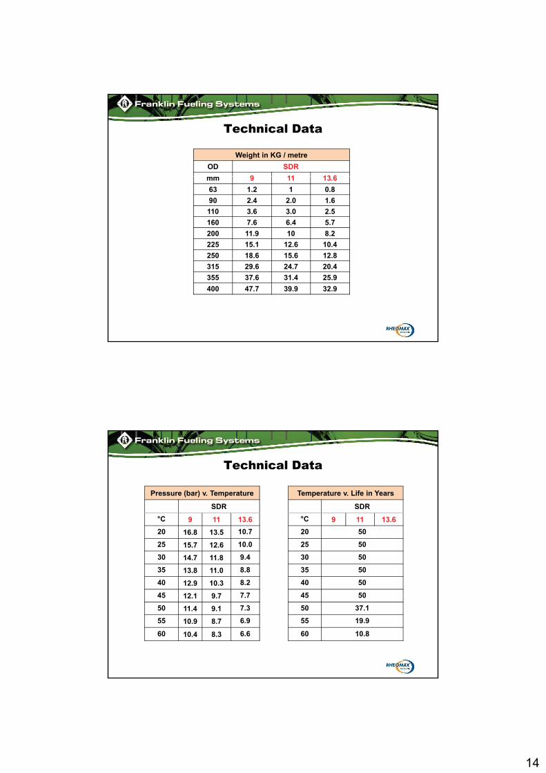
Technical Data
Weight in KG / metre
OD SDR
9 11 13 6mm 9 11 13.6
63 1.2 1 0.8
90 2.4 2.0 1.6
110 3.6 3.0 2.5
160 7.6 6.4 5.7
200 11.9 10 8.2
225 15.1 12.6 10.4
250 18.6 15.6 12.8
315 29.6 24.7 20.4
355 37.6 31.4 25.9
400 47.7 39.9 32.9
Technical Data
Pressure (bar) v. Temperature Temperature v. Life in Years
SDR SDR
°C 9 11 13.6 °C 9 11 13.6
20 16.8 13.5 10.7 20 50
25 15.7 12.6 10.0 25 50
30 14.7 11.8 9.4 30 50
35 13.8 11.0 8.8 35 50
40 12.9 10.3 8.2 40 50
45 12 1 9 7 7 7 45 5045 12.1 9.7 7.7 45 50
50 11.4 9.1 7.3 50 37.1
55 10.9 8.7 6.9 55 19.9
60 10.4 8.3 6.6 60 10.8

15
Technical DataAbove Ground Installation
Distance between Supports (Metres)
OD SDR
mm 9 11 13.6
63 1.1 1.1 1.090 1.4 1.4 1.3110 1.6 1.6 1.5160 2.1 2.0 1.9200 2.4 2.3 2.2225 2.6 2.5 2.4250 2 8 2 7 2 6250 2.8 2.7 2.6315 3.3 3.1 3.0355 3.6 3.4 3.2
400 3.9 3.7 3.5