a visualization system for integrating maintainability design and evaluation at product design stage
TRANSCRIPT

ORIGINAL ARTICLE
A visualization system for integrating maintainability designand evaluation at product design stage
Gaoliang Peng & Xin Hou & Jun Gao & Debin Cheng
Received: 29 October 2010 /Accepted: 12 October 2011 /Published online: 26 October 2011# Springer-Verlag London Limited 2011
Abstract Thoughtful consideration of products mainte-nance features early in design stage can reduce or eliminatemaintenance costs, reduce downtime, and improve safety.As such, the effective collaboration of product designersand maintenance technicians throughout the product designprocess is becoming much more important for the mostadvanced competitiveness. To address this need, a visual-ization system that enables maintainability-related techni-cians cooperated with product designers in a networkedmanufacturing environment is proposed in this study. Thispaper presents a systematic approach to implementation ofa Web-based visualization system by using virtual realitytechnology. The system aims at providing a simulatedenvironment and concurrent engineering processes to facil-itate communication, coordination, control, and integrationof product maintainability validation and improvementactivities. The result of this research will help increaseproduct maintainability, reduce development cycle time andcost, and hence increase product marketability.
Keywords Product maintainability . Maintenancesimulation and verification . Virtual reality .
Concurrent engineering
1 Introduction
The pressures of a global market continue to forcecompanies to consider all aspects of product performancein an effort to remain competitive. An important aspect ofproduct performance is maintainability. Maintainability isthe degree to which a product can be maintained or repairedeasily economically and efficiently. Many durable productsrequire maintenance throughout their useful life. Thoughtfulconsideration of products maintenance features early in thedesign process can reduce or eliminate maintenance costs,reduce downtime, and improve safety [1].
The contemporary concurrent engineering perspectiveencompasses many disciplines into a simultaneous part andsystem design paradigm, including reliability, productivity,quality, serviceability, human factors, safety, disassembly,and environmental concerns. In this background, the designfor X (DFX) conceptions, such as design for manufacturing(DFM), design for assembly (DFA), and so on, haveappeared and well concerned in product design process.For instance, many researches have focused on the field ofvirtual assembly and provided tools or technologies toenable user interactively perform assembly operations, planthe assembly sequence and path, check assembly interference,and analyze assembly performance of products in a realisticway. Such verifications could be available very early inproduct development before any physical prototyping andconsequently shorten the product development cycle andreduce development cost [2, 3].
Design for maintainability (DFMain) encompasses themeasures, in product design phase, to reduce the time andother resources spent in keeping a product performing well.It benefits the end user by reducing the total ownershipcosts through less downtime (lost productivity), lowermaintenance costs, less inventory, fewer tools, and improvedsafety and so on. Although DFMain was put forward for
G. Peng (*) :X. HouSchool of Mechatronics, Harbin Institute of Technology,Harbin, Chinae-mail: [email protected]
G. PengHarbin Institute of Technology,School of Computer Science and Technology,Harbin, China
J. Gao :D. ChengReliability and Environment Research Center,The No.5 Electronic Institute of Information Industry Ministry,Guangzhou, China
Int J Adv Manuf Technol (2012) 61:269–284DOI 10.1007/s00170-011-3702-y

decades, but it has not got equal regard as other DFXs. Inmany companies, for lacking a valid collaborative frame-work and an efficient computerized tool, the maintainabilitydesign and verification activities often carried out when thephysical product is manufactured. As a result, potentialmaintainability problems cannot be found out and correctedtimely. It often leads to being costly and time consuming.
To this regard, the objective of the paper is to present anapplication of the desktop virtual reality (VR) to develop anintegrated virtual maintenance system. In this system,maintainability-related technicians can cooperate withproduct designers to carry out and validate maintainabilitydesign based on digital prototypes in early design phase.
The organization of the paper is as follows: in the nextsection, related literature survey is introduced. Section 3describes the integrating of maintainability design andevaluation at product design stage. In Section 4, a task-based virtual maintenance prototype modeling approach isdiscussed. To realize information sharing, an extensiblemarkup language (XML)-based representation of virtualmaintenance process information is presented in Section 5.Section 6 gives implementation and application of proposedsystem to demonstrate its applicability. Concluding remarksand future directions are presented in Section 7.
2 Related research
2.1 Design for X
The number of different life-cycle aspects to be consideredhas led to the development of design for X where X standsfor an aspect under consideration, such as manufacturing,assembly, testability, reliability, maintenance, cost, and soon [4–10], for improvement in the design effort. DFX isone of the most effective approaches to implementingconcurrent engineering. Currently, various DFX tools areavailable to designers to better design their products.Boothroyd et al. [11] have suggested guidelines for designfor manufacture and assembly. These guidelines containgeneral best practice for design, such as minimizing thenumber of parts, using low-cost manufacturing operations,early prediction of the product cost, education, andexposing engineering designers to the production plant.
2.2 Virtual reality application in manufacturing
Virtual reality entails the use of advanced technologies,including computers and various multimedia peripherals, toproduce a virtual environment (VE) that users perceive ascomparable to real world objects and events. With the aidof specially designed transducers and sensors, users interact
with virtual objects, and performing actions in a way thatengenders a feeling of actual presence in the simulatedenvironment. VR technology has recently matured enoughto warrant serious engineering applications. Many researcheshave investigated the application of virtual reality techniquesto their design and manufacturing processes.
VR technologies are widely employed in the productdevelopment process. In engineering, VR is widely used tocreate digital prototypes to save time and money spent onmanufacturing physical prototypes. Janus et al. [12]developed a Web-based virtual interactive system tosupport product concept design. Antonya et al. [13]demonstrated the practicality, flexibility, and versatility ofthe visualization in a virtual environment in designevaluation and modification in order to realize VR andCAX integration in CAD/CAM environment, Barbieri et al.[14] developed four software interfaces, able to create aneasy data exchange link between VR and other design toolslike CAD, CAE, and computer-aided control engineering.Jimeno et al. [15] analyzed the technological advances inVR that have taken place over the last decade from thepoint of view of CAD/CAM.
Virtual assembly is one of the applications using VRtechnology. It allows a user to perform mechanicalassembly task in a virtual environment, so that the usercan evaluate the possibility of assembly before thosemechanical parts are actually manufactured. The user canmove around the virtual environment, use his hand,represented by a virtual hand in a virtual environment, togrip parts and assemble it. This brings the user a greatfeeling of immersion. This feeling will be enhanced if theinteractive dynamic simulation is implemented in thevirtual environment. Jayaram et al. [16] have developed avirtual-reality-based application to facilitate the planning,evaluation, and verification of a mechanical assemblysystem. Ye et al. [17] presented an experiment by whichexamines the potential benefits of using VR environmentsto support assembly planning. To this end, the assemblyplanning performance of subjects in traditional and VRenvironments are compared. The obtained results show thata VR environment has the potential to offer a more natural,powerful, economic, flexible platform than a traditionalengineering environment to support assembly planning.Jayaram et al. [18] have presented case studies in usingimmersive virtual assembly technology for projects inindustry. The case studies selected real-life industrysituations from industry members of the consortium andused the immersive virtual assembly technology to create ameaningful simulation. Virtual technology allows ergono-mists and engineers to perform virtual builds, and the rapidadoption of virtual tools pose an opportunity to integrateconsiderations of ergonomics into early design phase. Zhu
270 Int J Adv Manuf Technol (2012) 61:269–284

et al. [19] proposed an interactive assembly tool planningapproach based on assembly semantic model. In our earlywork [20, 21], we have developed a desktop VR system formodular fixture configuration design and assembly.
Unlike fully immersive VR system which use special-ized interaction devices such as head-mounted displays tocreate a sense of presence for the user within the 3D world,desktop systems exploit general-purpose hardware forinteraction (PC, mouse, and keyboard) and althoughobviously offer a much reduced sense of presence in theVE, are still useful for many application areas [22]. Guptaet al. [23] have developed a desktop system called thevirtual environment for design assembly. Zhou [24]developed a virtual injection molding system. This initialprototype system proves the feasibility of this designenhancement tool, and can provides a test bed and valuableinformation of injection molding that otherwise requirestime-consuming and expensive physical experimentation.The virtual environment can also assist in training molddesigners and process engineers about machine operation,mold design, and molding behaviors.
2.3 Virtual maintenance
The simulation of maintenance operations allows maintain-ability analysis from early design phases. The “virtualmaintenance system” has been designed to comparedeterioration behavior of virtual products and real productsby means of multimedia, haptic devices, and remotesensors. Since maintenance operations are usually per-formed in a restricted space within a limited time span, theoperator’s movements are often constrained by the sur-rounding components and contacts and clashes betweencomponents are inevitable, virtual maintenance environ-ment can reduce those unforeseen problems at the stage ofdesign. Using virtual environment, product maintainabilitycan be assessed before physical prototype being made.
Many researchers have worked on this field andproposed different solutions. Li et al. [25] proposed anobject-oriented prototype system called V-REALISM formaintenance training. Abate et al. [26] presented a bettersolution, which is a combination of VR techniques andhaptic interaction to simulate machine assembly mainte-nance process for aerospace industry. Collaborative VR hasbeen used to develop remote maintenance operationsimulation [27–29]. Virtual maintenance systems were alsoapplied in maintenance task planning [30], maintenanceplanning [31], and maintenance process simulation [32].Murray et al. set up an immersive virtual prototypingenvironment for supporting the product assembly andmaintenance [33]. In [34], a novel assembly optimizationframework based on genetic algorithm was proposed; the
framework allows a user to determine an optimal plan for amaintenance process by following an optimal assemblysequence and considering path planning factors.
Virtual human techniques have been used a lot in industrialdesign in order to consider human factors and ergonomics asearly as possible, and it has been integrated into VRapplications to complete ergonomic evaluation tasks. Digitalhuman simulation in virtual environment is used to assess thedifficulty of manual handling operations in maintenance andassembly process [35–37]. Haptic VR technology interfacehas been used for maintainability analysis of Rolls-Royceaircraft engines. A haptic system called REVIMA [38] wasdeveloped and used for the maintainability analysis. Theauthors have concluded that the virtual haptic interface canbe used directly in industries to address maintainability andto eliminate expensive physical mock-ups. More researchesin the field such as maintainability evaluation [39], remotediagnosis, and virtual maintenance system [40, 41] etc., canbe found in the recent literature.
2.4 Discussion on related research
From the literature, although the DFX tools available arerapidly increasing, very few allow maintainability designand assessment in product design phase. Some researchersfocused on providing maintainability and safety assessmentfunction embedded into CAD software in the designprocess. The approach is aimed to assist product designersfor taking into account maintenance factors in their work.
With the wide use of VR in the engineering field, manyresearchers induced VR technology into the maintenancearea. By using the powerful capability of interactive andsimulation of VR system, the number of VR tools, formaintenance training, maintainability verification, and soon, have been developed in recent years.
However, these researches are focused on developingstandalone computer-aided tools or approaches for productmaintainability improvement. For author’s knowledge, anintegrated system, to connect the product designer, main-tainability design technicians, maintainability verificationtechnicians, and maintenance operators, has not been dealtwith. Research on Internet-based virtual maintenancesystems presently only uses the Internet as a medium forremote diagnosis or maintenance simulation operation. Theneed for maintainability improvement of cooperation andcommunication between different maintainability techni-cians is also not dealt with.
The research presented in this paper offers a solution tothese issues by describing a visualization system that iscapable of integrating product designers and maintainabilitytechnicians for maintainability improvement in a unit VR-based platform.
Int J Adv Manuf Technol (2012) 61:269–284 271

3 Integrating of maintainability design and evaluationat design stage
By taking the advantage of concurrent engineering (CE), adesktop VR-based visualization system, to support main-tainability design and evaluation at the product designstage, is presented. The objective of this system is to findout and solving possible maintenance design limitations,which is often found after the physical prototype ismanufactured, and at worst some limitations may beexposed during the course of use. So it is a fundamentalmeans to improve the maintainability of complex productthat using an assisted tool to integrate product designers,maintenance technicians in a unit platform during productdesign process.
The development of VR applications in engineering hasopened up a powerful tool to solve the problem likeassembly planning problem. Instead of abstract, algorithmicassembly planning, an engineer can perform the assemblyintuitively in the virtual environment using VR hardwareand software [15]. The proposed system is to explore thepotential of using virtual reality technologies in mainte-nance operation simulation and evaluation. With the digitalinformation of product prototype, maintenance process, andmaintenance tool prototypes, the assembly and disassemblyactivities of maintenance operation is simulated. Then theinformation generated by this process can be used formaintenance design and verification.
The framework for supporting maintainability designand evaluation at design stage is shown in Fig. 1. Thesystem implies a distributed platform that allows geograph-ically separated users to communicate within the integratedinformation framework through connected networks suchas LAN or the Internet. In our application, designers buildproduct 3D model within CAD system, dedicate modelingmodule is used to automatically convert product CADassemblies to virtual maintenance prototype (VMP). Thenstructure designers can check the maintainability like toolaccessibility and operation space for tools or hands. If thereare some problems, they can revise their design structure toimprove the maintainability.
By using proposed application system, the maintainabil-ity design technician is presented with a virtual mainte-nance scene, in which various parts are initially locatedwhere they would be in the real maintenance plant. Theuser can then deal with maintainability design work,includes maintainability preduct, maintainability allocation,and detailed maintenance operation instruction building,with the help of interactivity and immersive of virtualenvironment. The powerful simulation design scene enablesthe user to make decisions, make design changes based onthe realistic models and simulation operations. During this
process, any product design change advice can be feedbackto product designers for consideration. In addition, thesystem automatically recorded the maintenance actionsimulations and these information can be used generateinstructions for maintenance operator training.
Within the virtual maintenance scene, the maintainabilityverification technician can assess and validate the productmaintainability from more professional view. This workcommonly carried out when the physical prototype ismanufactured. Similarly, any suggestions will be feedbackto maintainability design technicians for maintainabilitydesign modification and to product designers for productdesign improvement. The cooperation of product designers,maintainability design technicians, and maintainabilityverification technicians provides an efficient way to achievebetter product maintainability at the design phase.
In addition, proposed software platform presents anotherfunction for maintenance operator training before thephysical product is manufactured. The trainees can interactwithin the virtual scene, either moving freely and touchingmodels or grasping a model. With the defined maintenanceoperation instructions, the system may guide the user toundertake a maintenance task in virtual space. Moreover, tovalidate the operation activities, whenever a trainee tries tomove the grasped object, the system can validate themovement considering potential collisions with the rest ofthe objects within the scene. So the system affords themaintenance operation trainees an early and more immersedview of the maintenance procedures for learning (access,position, tool use, etc.)
4 Virtual maintenance prototype
4.1 A task-based VMP model
Generally, virtual maintenance is considered as simulatedactivities and process based on virtual maintenance proto-type of product, to implement maintainability analysis andevaluation or maintenance operation training. Since VMP isconstructed from CAD model of product, it contains thebasic hierarchical function structure and assembly relation-ship of CAD model. Considering that most maintenancework, in real situation, is just dealing with part of productlike component or subsystem. It enlightens us to present amaintenance-task-oriented VMP modeling method. Thismethod is capable of constructing VMP based on compo-nents or subsystems may be disassembled during mainte-nance task, instead of the whole product structure. Thus themodel is far less complicated and therefore achieves hightransmission speed via internet and fast rendering in virtualenvironment.
272 Int J Adv Manuf Technol (2012) 61:269–284

Considering to the requirements of application, proposedVMP consists of information as:
(1) Visual data Geometric object in VE is polygon-based model, so visual data of VMPrefers to the thousands of polygons,includes rendering feature like materialand texture, which enables productmodel visualization in VE.
(2) Hierarchicalrelationship
On the basis of function or spatialdecomposition, a product can bedivided into different subassembliesand parts. The subassemblies canfurther be divided into othersubassemblies and parts. This meansthe hierarchy of VMP can be createdand represented as a tree structure inwhich the root node of the treerepresents the assembly product, theintermediate nodes represent thesubassemblies and the leaf nodesrepresent the single components.
(3) Assemblyrelationship
An assembly relationship indicateswhich components are assembled andtheir corresponding joiningrelationships.
(4) Physicalattributes
It includes material, weight, stiffnessetc. of a component.
(5) Behaviors VMP is not only taking the displayinformation of a real product and it iscomposed components, but theirbehaviors, for example, pressing a startbutton of a machine will generate astart event.
(6) Constraints It describes some information orconstraint for maintenance operation,for instance, to dismount a hexagonalsocket nut must use a wrench withright specifications.
Moreover, proposed VMP model should support easilyrefreshed when the product assembly model is revisedduring design process. Because product design is agradually advancing process, from concept design to detail
Maintenance operator
Maintainability design technician
Product designer
Virtual prototype modeling
Product CAD model
Maintenance device & tool
modeling
Maintenance simulation
Maintainability analysis & evaluation Maintainability
verify report
Maintenance operation video
Maintenance instruction
Maintenance operation training
Operation process record
Maintenance procedure
Maintenance procedure design
&optimalTool
model
Maintainability design
knowledge
Product design revise advice
Product design revise advice
Maintainability verification technician
Maintainability design revise
advice
Virtual prototype
Fig. 1 The framework for supporting maintainability design and evaluation at design stage
Int J Adv Manuf Technol (2012) 61:269–284 273

design, to create a product to appeal to the identifiedmarket, and finally, testing, modifying, and refining theproduct until it is ready for production. So the productdesign model is in dynamic modification and refinement.
Extensible markup language [42] is a simple, veryflexible text format derived from SGML and widely usedas exchange format of data on the Web and elsewhere. It isa standard to exchange structured documents and data inthe Internet environment. XML allows users to define tagsarbitrarily. It stores the structure and meaning of datawithout any changes. It is applied to exchange data withother systems. XML displays various characters through theUnicode and is independent upon languages. Therefore,XML exchanges information in heterogeneous platformsand systems.
To this regard, using XML schema, a task-based VMP(TVMP) model is discussed in this section. The modelprovides extensible and flexible modeling method tomanage VMP information for maintenance simulation inVE. Since XML is not restricted to a fixed number of tags,it allows us to define our own structure and tags necessaryfor VMP representation.
The model supports a clear hierarchy representing theproduct structure and its elements. Figure 2 shows theXML schema structure of VMP model. The structureconsists of “Baisc_Info”, “Assembly_Info,” and “Child_List”. “Baisc_Info” describes the characteristics of VMP(“ID”, “Name”, “UpdateTime”, “Designer” represent therelevant information of VMP building, while “TaskID”
refers to this VMP is used for which of maintenance tasks).“Assembly_Info” is to represent positional and assemblyinformation of VMP. “Initi_pos” means the initial positionwhen the VMP is built and loaded into VE and “Cur_pos”is used to record the position of VMP after operating.Positional information is constructed with transformationmatrices (translational vectors (P1–P3), rotational vectors(O1–O3), and a scale vector (W)). “Mate_Info” representsthe assembly relationship of VMP with other subassembliesor parts. “Child_List” represents the list of composedsubassemblies and parts of VMP. “Part_Info” is an entityrepresenting the information of a part, in which the “Name”,“ID,” and assembly information called “Assembly_Info” areincluded. Moreover, a part node links a geometry filecontains physical visual data of a part model. Usingrecursion structure, “Sub_VMP” follows the same structureof VMP and links a sub-VMP file, the sub-VMP may adoptother sub-VMPs. As the XML data is designed according tomulti-level VMP schema, higher and/or lower stage searchesare conducted conveniently. Moreover, it is convenient forVMP updating, if a subassembly or part is modified, onlyfew information need to be changed in the parent or higherlevel of VMP. We just need to modify the linked sub-VMPmodel accordingly (Fig. 3).
4.2 TVMP construction
VMP is built based on the product CAD data. As shown inFig. 4, three kinds of information will be extracted from
Fig. 2 XML schema structurefor VMP representation
274 Int J Adv Manuf Technol (2012) 61:269–284

a
b
Fig. 3 a A safe valve andits decomposition model. b TwoTVMP models generatedfrom VMP
Int J Adv Manuf Technol (2012) 61:269–284 275

CAD data, namely, visual data, hierarchical structure, andassembly relationship. In this research, visual data aregenerated separately as the component VRML file. The filecontains thousands polygons by meshing surfaces of CADsolid model. And this meshing function is directly providedby most CAD software. In addition, to get different level ofdetail (LOD) model of component, a mesh rebuildingmethod is designed in this research, which can generatedifferent LOD models based on the VRML file outputtedfrom CAD software. Thus for a component, several VRMLfiles is linked and available for use. Then by readingVRML file and extracting polygons, the component visualmodel can be loaded into VE.
The hierarchical structure corresponding to functional orspatial construction relationship of a product is obtainedthrough extraction from product structure tree of CADassembly model. And an XML writer generates an XMLfiles according to the XML schema structure shown inFig. 4 for the VMP modeling. The XML writer wasdeveloped by using Xerces XML Parser [43]. The assemblyrelationship corresponding to the assembly consists of theconnecting and position information as matrices areextracted by a translator module, which was developed byusing API functions of CAD software (in this research,UG/Open is used for extracting assembly informationfrom UG model).
After the above process, basic geometric information ofVMP is constructed. Other information, include physicalattributes, behavior attributes, and operation constraints, areautomatically generated or manually added with providedinterface. For example, the weight of a component can becalculated if its material was selected by the user. All theseinformation are saved in tags of XML document of VMPand can be easily retrieved to use.
VMP contains all components of CAD data was builtand saved in resource database of server. Generally,TVMP is used in a maintenance task and only some ofcomponents are involved. Thus, TVMP can be consideredas a simplified VMP. In this research, most work of
construction of TVMP from VMP is manual. The userselects which subassemblies or components are used andalso appoints which level of detail visualization modelfor a component. Similarly, an XML document forrepresenting of TVMP was generated. The TVMPinformation also saved in resource database for differentclients downloading.
Product design is a gradual advancing process ofmodifying and refining of design model. TVMP modelsupports information conveniently updated whenever thedesign model was modified.
5 Virtual maintenance procedure informationrepresentation
To establish a virtual maintenance environment and supportmaintenance operation based on virtual prototypes, it isimportant to define a modeling scheme to represent andstore the procedures and resources information. Theflowchart of maintenance procedure related information inthe integrated system is shown in Fig. 5. At maintainabilitydesign phase, the maintenance engineer decomposes themaintenance action step by step for a given item, and alsoappoints the needed support tools and equipments for eachstep. As a result, a preliminary maintenance procedure willgenerate. At the next phase, along with the maintainabilityverification, the preliminary maintenance procedure will bechecked and optimized. Corresponding work includes: (1)odification of the operation steps according to virtualmaintenance test activities. (2) Reconsideration of supporttools and equipments list. That is because during themaintainability analysis and evaluation process, somemaintenance shortcoming may be found, for example,inadequate workspace for accessing a given item, collisionoccurring when assemble/disassemble a component, and soon. In addition, through maintainability optimization, thestructure or component may be changed, so we must give aglobal reconsideration of support resources.
Fig. 4 Process of VMPconstruction
276 Int J Adv Manuf Technol (2012) 61:269–284

According to the modified maintenance procedures, wecan perform interactive maintenance operation in VE.During this activity, users play an important part and havea maintenance worker role that allows them to interact withthe virtual prototype. When they select maintenance toolsor equipments to disassemble/assemble a part or a compo-nent to accomplish a maintenance task, the detailed
operation process will be automatically recorded intoproposed information model. These information help toform visualization procedure that allows generating main-tenance operation animate. The animate can then be used totrain the maintenance operators.
The information model is not only described as data setwhich contains maintenance operation description, support
Fig. 5 Flowchart ofmaintenance procedure inproposed system
Operate step
Operat_info
Basic_ info
Type
Content
ID
Mean
Area
Note
Channel
Operator_ info Specialty
Skill
Number
Object_ info
Name
ID
Operat_ list
Path_file
Tool_ info
Name
ID
Path_file
Viewp_ info
ID
Path_file
Initial_pos
End_pos
Initial_pos
End_pos
Initial_pos
End_pos
P2
P3
P1
O1
O2
O3
W
Fig. 6 XML schema structurefor maintenance simulationinformation representation
Int J Adv Manuf Technol (2012) 61:269–284 277

equipment tool list, and other necessary attributes, but alsorepresented in a manner that allows efficient retrieval, easymaintenance, and transmission via network.
The maintenance procedure information is used toprovide all necessary data for virtual maintenance opera-tion. To this end, the following kinds of information shouldbe contained in this model: (1) operate basic informationsuch as the ID, operate type, operate mean, work area, andchannel; (2) operator information including the number,specialty, and skill level of worker; (3) recorded operateprocess information such as related animation data ofcomponent, tool, and viewpoint. When representing datausing XML, a document scheme definition has to bespecified first. This would govern the data structurecontained by the XML file. Figure 6 shows the structureof the XML object for maintenance operate steps informa-tion representation. Tags in XML follow a hierarchicalstructure. Necessary information of operate procedure canbe well organized in a single XML file. According to the
defined XML scheme, the complex information of amaintenance procedure can be saved in a single XML file.
6 System implementation and application
6.1 Implementation
The system of manufacturing proceeding managementplatform in space production enterprises is shown inFig. 7. It is divided into four parts, namely protocol layer,data layer, technique layer, and application layer.
1. Protocol layer stipulates Internet Protocol (TCP/IP,SAOP), Data Exchange Protocol (XML, STEP), andthe port of scalable application.
2. Data layer consists of two modules: domain knowledgemanagement and resources management. This layersupplies data managing environment for supporting
Tools
Equipments VMP
VEModels
Fixtures
Maintenanceprocess
Resource base
Processknowledge
Rules Cases
Optimizationalgorithm
Productknowledge
Collaborationsolutions
Knowledge base
Knowledge management Resource management
Communicate protocol
TCP/IP, SOAP
Data exchange protocol
XML, STEPExpandable API
Maintenanceoperation training
Maintainabilitydesign
Productdesign
Maintainabilityevaluation
Interfacemanagement
Application modulemanagement
DataManagement
Fig. 7 Architecture of integrated virtual maintenance system
278 Int J Adv Manuf Technol (2012) 61:269–284

maintainability design and verification in design phase.It provides necessary knowledge and resources used intechnique layer. Domain knowledge stored in knowledgedatabase includes maintenance relevant rules, process,and algorithms. Resources database consists of mainte-nance equipment, fixture and tool model database, VMPdatabase, and maintenance process database.
3. Technique layer has two modules, namely maintain-ability design and verification module and virtualmaintenance simulation environment. The first moduleis used for maintainability design and assessment,while the second module is to provide an interoperativevirtual space for maintenance operation simulation.
4. Application layer provides user interfaces to deal withrelevant application work like maintainability design,maintainability evaluation, and maintenance operationtraining.
Cooperating maintenance platform uses “lax coupling”to connect all submodules or systems. It means that thesystem use simple data messages to communicate. Simpledata messages are denoted in the form of XML text andothers are denoted in the form of XML schema.
The GUI of proposed system is illustrated in Fig. 8. Thecenter is virtual maintenance environment. The top left of
the window shows hierarchical structure of product, whilethe bottom left window is used for listing maintenancedevice/tool nodes used in a certain task. The right windowshows maintenance operation steps and their detailedinformation of maintenance task. The bottom window isused for information output.
6.2 Application
The system has been applied to an industrial productsuccessfully, and a case study for a wheeled mobile robot,is used here to demonstrate the maintainability design andverification functionality of the proposed system.
In this case, UG 4.0 is used as the geometric modeler. Asshown in Fig. 9a, after building a wheeled robot assemblywithin UG, the designer can import the assembly modelinto proposed system. The system automatically establishesthe VMP for the wheel as shown in Fig. 9b.
Based on maintainability prediction and allocation tomeet the design requirements, the axis cover is easily wornand need replaced. So a maintenance task of replacing theaxis cover is designed. Using the maintenance taskmanagement module, an operation process card is built, inwhich detailed information of each step, including opera-tion description, used test equipments and maintenance
Fig. 8 GUI of proposed system
Int J Adv Manuf Technol (2012) 61:269–284 279

Fig. 9 a Left wheel assembly model in UG. b Left wheel VMP converted from UG model
280 Int J Adv Manuf Technol (2012) 61:269–284

Fig. 10 a VMP and needed tool models are loaded into VE. b Dismounting a hexagonal socket nut with a wrench
Int J Adv Manuf Technol (2012) 61:269–284 281
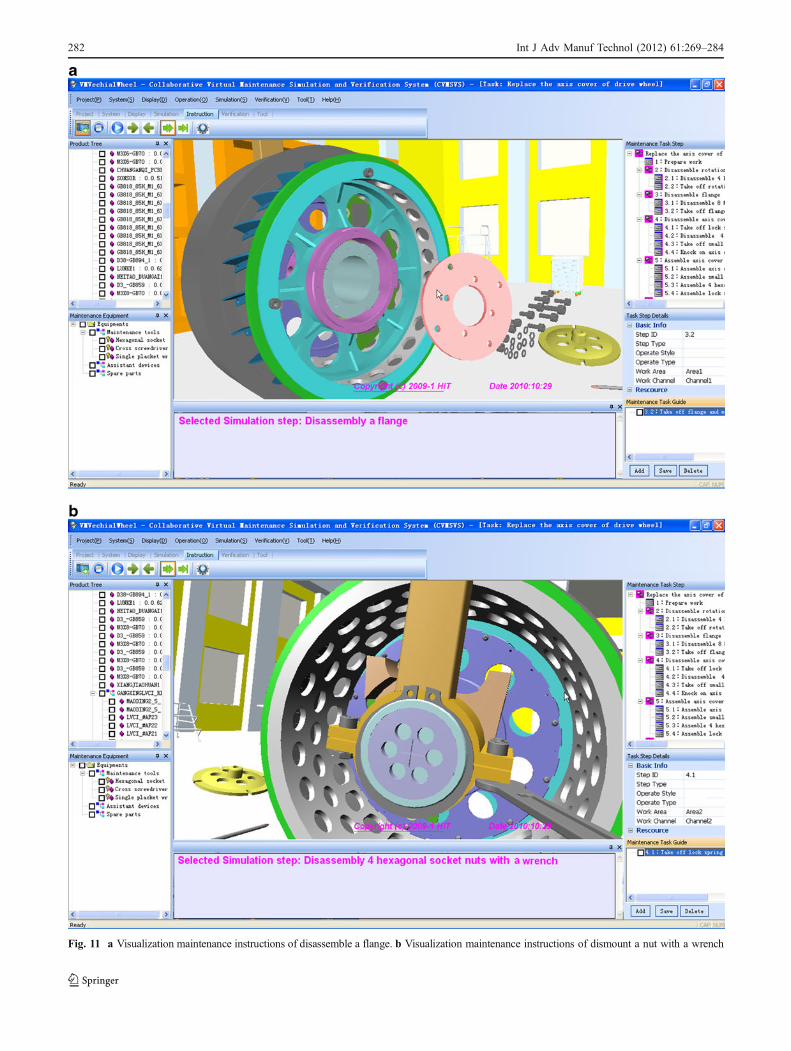
Fig. 11 a Visualization maintenance instructions of disassemble a flange. b Visualization maintenance instructions of dismount a nut with a wrench
282 Int J Adv Manuf Technol (2012) 61:269–284

tools, caution items, and so on, are inputted. In thisresearch, a friendly interface for maintenance task manage-ment is developed. Besides basic input function, it alsosupport to copy a step, or even a whole process card from apredefined cases. Thus, it can decrease the tedious textinput work.
Carrying out simulations of maintenance activitieswithin a virtual environment gives a user the ability todirectly interact with 3D virtual models for maintenancepurposes. Maintainability design technician can employ itto validate and optimize defined operation process of acertain maintenance task. The interactive operation processof maintenance technicians will be automatically recorded.This information composes the basic element of visiblemaintenance instructions for operation training. As shownin Fig. 10, to simulate the task of replacing the axis cover,VMP of wheel component and needed maintenance toolsare loaded into virtual environment. Then the user can dealwith maintenance simulation operation with digital modelsin virtual space.
With the interactive and simulation function of virtualmaintenance environment, maintainability verification tech-nician can evaluate aspects of maintainability design (acces-sibility, reachability, tool usability, part mount/dismountability) of product design to find out better design solutionsfrom the maintainability point of view. To speed up thechecking work, relevant rules and knowledge of maintain-ability design, from maintenance standards like MIL-HDBK-472 [44] are manually defined and saved in database. Thenthe system can guide the technician to review and validatethe maintainability design according to these rules. Itprovides the opportunity to find out better design solutionsfrom the maintainability point of view. The system recordsthe inputted verification information of user in this processand finally automatically generates a maintainability evalu-ation report. For instance, the accessibility of screwdriver todismount a screw needs to be improved, for there is notenough space for screwdriver rotation. This problem isrecorded and added in the report. Whenever the report sendsto product design, he/she may revise the design structure likeadjust the position of screw or other parts.
The system also provides an opportunity for mainte-nance operators training within an interactive, realisticvirtual reality environment. As shown in Fig. 11, thevisualization maintenance instructions can present to atrainee a vivid course of how to accomplish a maintenancetask. Disassembling and assembling movement of each partor component during the task is shown in sequence. Thetrainee can pause, playback, or select to certain steps toplay. Furthermore, taking the values of “learning by doing”,the trainee also can carry out virtual maintenance operationwith virtual models. But in this mode, the operations areconstrained and followed the designed maintenance steps.
7 Conclusions
This paper has presented the development of a visualizationsystem capable of carrying out maintainability design andverification in early product design phase. The system isaimed to integrate product designers and maintenancetechnicians into a whole framework and to allow the designto evolve as maintenance concepts are reviewed andrevised. VR-based system offers a more direct, intuitivecontrol over the interaction activity, thus speeding up themaintenance checks, along with the opportunity to find outbetter design solutions from the maintainability point ofview. Therefore, it paves the way for the critical maintain-ability design flaws to be corrected in a timely and cost-effective manner.
The product virtual maintenance prototype representa-tion and construction was presented. By using XMLschema, proposed model has well-designed hierarchicalstructure and conveniently simplified according to amaintenance task, or easily updated whenever the productdesign model was modified. An XML-based informationrepresentation approach for virtual maintenance process isalso discussed. This information representation approachsupports complicated virtual maintenance process informa-tion recording and management. That was used as animatemaintenance operation instruction to train maintenanceoperators. Finally, a case study is conducted with theimplementation of proposed system, which has shown thatthe proposed system worked effectively in supportingproduct maintainability design and verification in the earlystage of product design.
Future effort will concentrate on physical-based model-ing methods and add virtual human model in maintenanceoperation and simulation. Moreover, it is mentioned thatmore maintainability design and verification knowledgeand rules can be integrated in our proposed system toassist the designer via providing more information andguidance.
Acknowledgments The support of National Natural ScienceFoundation of China (no. 50905047), Research Fund for the DoctoralProgram of Higher Education of China (20092302120010), and ProjectSupported by Development Program for Outstanding Young Teachersin Harbin Institute of Technology (no. Hitqnjs2009013) in carrying outthis research is gratefully acknowledged.
References
1. Andrew K, Lee GH (1997) Design of parts and manufacturingsystems for reliability and maintainability. Int J Adv ManufTechnol 13:67–76
2. Liu Z, Tan J (2007) Constrained behavior manipulation forinteractive assembly in a virtual environment. Int J Adv ManufTechnol 32(7–8):797–810
Int J Adv Manuf Technol (2012) 61:269–284 283

3. Choi ACK, Chan DSK, Yuen AMF (2002) Application of virtualassembly tools for improving product design. Int J Adv ManufTechnol 19(5):377–383
4. Gehin A, Zwolinski P, Brissaud D (2008) A tool to implementsustainable end-of-life strategies in the product developmentphase. J Clean Prod 16(5):566–576
5. Huang SH, Kuo TC, Zhang HC (2001) Design for manufactureand design for ‘X’: concepts, applications, and perspectives. IndEng 41(3):241–260
6. Lai X, Gershenson JK (2008) Representation of similarity anddependency for assembly modularity. Int J Adv Manuf Technol 37(7/8):803–827
7. Skander A, Roucoules L, Meyer JSK (2008) Design andmanufacturing interface modelling for manufacturing processesselection and knowledge synthesis in design. Int J Adv ManufTechnol 37(5/6):443–454
8. Tichem M, Storm T (1997) Designer support for productstructuring—development of a DFX tool within the designcoordination framework. Comput Ind 33(2/3):155–163
9. Yang CC, Chen SH, Shiau JY (2007) A DFX and concurrentengineering model for the establishment of a new department in auniversity. Int J Prod Econ 107(1):179–189
10. Saygin C, Kilic SE (1999) Integrating flexible process plans withscheduling in flexible manufacturing systems. Int J Adv ManufTechnol 15(4):268–280
11. Boothroyd G, Dewhurst P, Knight WA (2001) Product design formanufacture and assembly. CRC Press, New York
12. Janus SL, Pan WW (2006) Conceptual design system in a Web-based virtual interacttive environment for product development.Int J Adv Manuf Technol 30:1010–1020
13. Barbieri L, Bruno F, Caruso F, Muzzupappa M (2008) Innovativeintegration techniques between Virtual Reality systems and CAxtools. Int J Adv Manuf Technol 38:1085–1097
14. Antonya C, Talaba D (2007) Design evaluation and modificationof mechanical systems in virtual environments. Virtual Reality11:275–285
15. Jimeno APuerta (2007) State of the art of the virtual realityapplied to design and manufacturing processes. Int J Adv ManufTechnol 33:866–874
16. Jayaram S, Connacher H, Lyons K (1997) Virtual assembly usingvirtual reality techniques. Comput Aided Des 29(8):575–584
17. Ye N, Banerjee P, Banerjee A, Dech F (1999) Assembly planningin traditional and virtual environments. IEEE Trans Syst ManCybern B 29(4):546–555
18. Jayaram S, Jayaram U, Kim YJ (2007) Industry case studies in theuse of immersive virtual assembly. Virtual Reality 11:217–228
19. Zhu H, Wu D, Fan X (2010) Interactive assembly tool planningbased on assembly semantics in virtual environment. Int J AdvManuf Technol 51(5–8):739–755
20. Peng G, Wang G, Liu W, Yu H (2010) A desktop virtual reality-based interactive modular fixture configuration design system.Comput Aided Des 42(5):432–444
21. Peng G, Xin H,Wu C, Jin T, Zhang X (2010) Fast collision detectionapproach to facilitate interactive modular fixture assembly design in avirtual environment. Int J Adv Manuf Technol 46:315–328
22. Sayers H (2004) Desktop virtual environments: a study ofnavigation and age. Interact Comput 16(5):939–956
23. Gupta R, Whiney D, Zeltzer D (1997) Prototyping and designfor assembly analysis using multimodal virtual environments.Comput Aided Des 29:585–597
24. Zhou H, Shi S, Ma B (2009) A virtual injection moldingsystem based on numerical simulation. Int J Adv ManufTechnol 40(3–4):297–306
25. Li JR, Khoo LP, Tor SB (2003) Desktop virtual reality formaintenance training: an object oriented prototype system (V-REALISM). Comput Ind 52(1):109–125
26. Abate AF, Guida M, Leoncini P, Nappi M, Ricciardi S (2009) Ahaptic-based approach to virtual training for aerospace industry. JVisual Lang Comput 20(1):318–325
27. Haist B (2008) Setting up and managing a remote maintenanceoperation for fusion. Fusion Eng Des 83(1):1841–1844
28. Bellamine M, Abe N, Tanaka K, Chen P, Taki H (2004) Avirtual reality based system for remote maintenance of rotatingmachinery. Embedded and Ubiquitous Computing, LNCS3207:223–232
29. Jenab K, Zolfaghari S (2008) A virtual collaborative maintenancearchitecture for manufacturing enterprises. J Intell Manuf 19(1):763–771
30. Leino SP, Lind S, Poyade M, Kiviranta S, Multanen P, Reyes-Lecuona A, Mäkiranta A, Muhammad A (2009) Enhancedindustrial maintenance work task planning by using virtualengineering tools and haptic user interfaces. Virtual and MixedReality, LNCS 5622:346–354
31. van Houten FJAM, Kimura F (2000) The virtual maintenancesystem: a computer-based support tool for robust design, productmonitoring, fault diagnosis and maintenance planning. Annals ofthe ClRP 49(1):91–94
32. De Sa AG, Zachmann G (1999) Virtual reality as a tool forverification of assembly and maintenance processes. ComputGraph 23(1):389–403
33. Murray N, Fernando T (2004) An immersive assembly andmaintenance simulation environment. Proceedings of the EighthIEEE International Symposium on Distributed Simulation andReal-Time Applications 04(1):1550–6525
34. Christiand YJ, Kumar P (2009) A novel optimal assemblyalgorithm for haptic interface applications of a virtual mainte-nance system. J Mech Sci Technol 23(1):183–194
35. Ma L, Chablat D, Bennis F, Zhang W, Hu B, Guillaume F (2011)Fatigue evaluation in maintenance and assembly operations bydigital human simulation in virtual environment. Virtual Reality15:55–68
36. Chaffin D (2002) On simulating human reach motions forergonomics analyses. Hum Factors Ergon Manuf 12(3):235–247
37. Chaffin D (2007) Human motion simulation for vehicle andworkplace design. Hum Factors Ergon Manuf 17(5):475
38. Borro D, Savall J, Amundarain A, Gil JJ, Garcia-Alonso A, MateyL (2004) A large haptic device for aircraft engine maintainability.EEE Comput Graph Appl 24(6):70–74
39. Chabal C, Megard C, Sibille L (2005) EMM-3D: a virtualenvironment for evaluating maintainability from CAD models.Laval Virtual 2005:20–24
40. Wang JF, Tse PW, He LS, Yeung RW (2004) Remote sensing,diagnosis and collaborative maintenance with Web-enabled virtualinstruments and mini-servers. Int J Adv Manuf Technol 24(1):764–772
41. Elzendoorn B, de Baar M, Chavan R et al (2009) Analysis of theITER ECH upper port launcher remote maintenance using virtualreality. Fusion Eng Des 84(1):733–735
42. Skonnard A, Gudgin M (2001) Essential XML quick reference: aprogrammer’s reference to XML, XPath, XSLT, XML Schema,SOAP and More. Addison-Wesley Pub Co; 1st edition. ISBN021740958
43. Xerces C++ XML Parser. <http://xml.apache.org/xerces-c>, 200544. Military Standardization Handbook MIL-HDBK-472. Maintain-
ability Prediction, US Department of Defense. 1966
284 Int J Adv Manuf Technol (2012) 61:269–284