a vlc channel model for underground mining environments
TRANSCRIPT

SPECIAL SECTION ON COMMUNICATIONS IN HARSH ENVIRONMENTS
Received September 7, 2020, accepted October 4, 2020, date of publication October 13, 2020, date of current version October 21, 2020.
Digital Object Identifier 10.1109/ACCESS.2020.3030615
A VLC Channel Model for Underground MiningEnvironments With Scattering and ShadowingPABLO PALACIOS JÁTIVA 1, (Graduate Student Member, IEEE),CESAR A. AZURDIA-MEZA 1, (Member, IEEE), IVÁN SÁNCHEZ2,FABIAN SEGUEL3, DAVID ZABALA-BLANCO4, ALI DEHGHAN FIROOZABADI 5,CARLOS A. GUTIÉRREZ 6, (Senior Member, IEEE), AND ISMAEL SOTO3, (Member, IEEE)1Department of Electrical Engineering, Universidad de Chile, Santiago 8370451, Chile2Department of Telecommunications Engineering, Universidad de las Américas, Quito 170503, Ecuador3Department of Electrical Engineering, Universidad de Santiago de Chile, Santiago 9170124, Chile4Department of Computing and Industries, Universidad Católica del Maule, Talca 3466706, Chile5Department of Electricity, Universidad Tecnológica Metropolitana, Santiago 7800002, Chile6Faculty of Science, Universidad Autónoma de San Luis Potosí, San Luis Potosí 78290, Mexico
Corresponding authors: Cesar A. Azurdia-Meza ([email protected]) and Iván Sánchez ([email protected])
This work was supported in part by the Doctoral Fellowship Grant from ANID PFCHA/Doctorado Nacional/2019-21190489; in part by theUDLA Telecommunications Engineering Degree; in part by Project STIC-AMSUD 19-STIC-08; in part by ANID FONDECYT RegularNo. 1201893; in part by Vicerrectoría de Investigación y Desarrollo (VID) de la Universidad de Chile Proyecto ENL 01/20; in part bySENESCYT ’’Convocatoria abierta 2014-primera fase, Acta CIBAE-023-2014’’; in part by ANID FONDECYT PostdoctoradoNo. 3190147; and in part by the Grupo de Investigación en Inteligencia Artificial y Tecnologías de la Información (IA&TI).
ABSTRACT Underground mining is an industry that preserves the miners’ safety and efficiency in theirwork using wireless communication systems as a tool. In addition to communication links characterized byradio frequency signals, optical links in the visible light spectrum are under intense research for undergroundmining applications due to their high transmission rates and immunity to electromagnetic interference.However, the design of a robust visible-light communication (VLC) system for underground mining is achallenging task due to the harsh propagation conditions encountered in mining tunnels. To assist researchersin the design of such VLC systems, we present in this paper a novel channel model that incorporatesimportant factors that influence the quality of the VLC link in underground mines. Features such as anarbitrary positioning and orientation of the optical transmitter and receiver, tunnels with irregular walls,shadowing by large machinery, and scattering by dust clouds are considered. These factors are integratedinto a single modeling framework that lends itself for the derivation of compact mathematical expressionsfor the overall DC gain, the impulse response, the root mean square delay spread, and the received power ofthe proposedVLC channel model. Our analytical results are validated by computer simulations. These resultsshow that the rotation and tilt of the transmitter and receiver, as well as the tunnels’ irregular walls have anotorious influence on the magnitude and temporal dispersion of the VLC channel’s line of sight (LoS) andnon-LoS components. Furthermore, results show that shadowing reduces the LoS component’s magnitudesignificantly. Our findings also show that scattering by dust particles contributes slightly to the total VLCchannel gain, although it generates a large temporal dispersion of the received optical signal.
INDEX TERMS Channel impulse response, channel modeling, scattering, shadowing, underground mining,visible light communication.
I. INTRODUCTIONThe inherent working environment of underground mines isconsidered as very dangerous and unsafe due to inherentss
The associate editor coordinating the review of this manuscript andapproving it for publication was Qiong Wu.
characteristics of the tunnels [1], as well as numerous externalagents generated by regular mine operation such as dust,toxic components, sewage water, among others [2]. Thesefactors make the underground mining environment be con-sidered one of the most harsh environments for work andfor establishing reliable communication links [3]. To manage
VOLUME 8, 2020 This work is licensed under a Creative Commons Attribution 4.0 License. For more information, see https://creativecommons.org/licenses/by/4.0/ 185445

P. P. Játiva et al.: VLC Channel Model for Underground Mining Environments With Scattering and Shadowing
day-to-day communication, along with the emergencies thatcan occur in this environment (landslides, fires, or intox-ication of workers), an stable communication system isrequired [4]. This system must be designed to support appli-cations focused on reliably localize and monitor infrastruc-ture, and provide real-time information of all personnelwithin the tunnel infrastructure [5]. However, the physicalconditions of the underground mines present a challenge fordeveloping reliable and effective communication systems.
The geometric characteristics of the underground mineenvironment (the shape of walls and roof), as well as the inter-ference and electromagnetic noise produced by the machin-ery employed in mining contributes to the difficulty of thecommunication system design [6]. In other words, the pre-vious factors cause problems in the communication systemsfrequently used in mines, which are normally based on radiofrequency (RF). Among the main complications of RF-basedunderground mining communications systems are a poor biterror rate (BER), a high delay spread in the signal, and alimited data transmission rate [7]. One solution to these issuescomes from the combination of RF technologies with thenovel scheme termed as visible light communication (VLC),which also provides continuous lighting within the under-ground mining environment [8].
VLC systems have several benefits, such as the use ofunlicensed spectrum ranging from 400 THz to 800 THz,system elements with reasonable prices, and immunity to theelectromagnetic interference, for instance [9], [10]. Theseadvantages make VLC a good candidate to get a secure,robust, and reliable communication in underground miningenvironments [11]. Unfortunately, in this physically com-plex environment, the channel modeling tends to be morechallenging in comparison to the traditional indoor scenarioswhere a VLC link is generally adopted [12].
An underground mine is composed by irregular tunnels,which present features that do not appear in typical indoorenvironments [13]. Factors such as dust particles that causescattering, heavy machinery that generates shadowing, andnon-flat walls and ceilings, which require angular positioningof the light emitting diodes (LEDs) and photodiodes (PDs)to provide better illumination and light reception inside thetunnel respectively are challenging for the VLC design inmining environments. On the other hand, it is well knownthat by modeling the communication channel, the overallsystem performance may be enhanced by using dedicatedtime/frequency techniques [14]. To the best of our knowledge,specifically applied to underground mining VLC systems,no channel model that considers its complicating characteris-tics has been presented. Based on an extensive review of thestate of art (see Section II), and in an effort to design betterunderground mining communication systems, we present aVLC channel model that considers physical features thatwill have an effect in mining tunnels. We characterize andinclude in the underground mining VLC channel model thetilt and rotation of LEDs and PDs that impact the line ofsight (LoS) and non-LoS components of the optical link.
The characterization of non-flat walls in tunnels and theirreflection effects in the optical signal are further considered.Finally, a scatteringmodel that considers a disk-shaped distri-bution of the dust particles around the optical receiver, and ashadowing model that takes into account the entry of objectsinto the mining scenario are considered. The inclusion of theaforementioned parameters help us to understand the differ-ences between a referential (typical indoor) VLC channel andthe undergroundminingVLC channel. For channelmodeling,we use the ray tracingmethodology, which allows an accuratedescription of the interaction of rays emitted from LEDs toPDs within the underground mining environment.
The main contributions of this paper are summarized asfollows:
1) Discussing the differences between the proposedunderground mining VLC channel and the typicalindoor VLC channel, which is used as a referenceVLC channel model.
2) Adjusting and analyzing the effect of non-flat andnon-regular tunnel walls, that generate non-orthogonalreflections, to properly model the optical signal in theproposed underground mining VLC channel.
3) Proposing a ray tracing-based underground miningVLC channel model that includes the effects of scat-tering and shadowing phenomena due to the presenceof dust particles and objects (machinery), respectively.Firstly, the entry of objects that cause shadowing in themining scenario is statistically modeled through a Pois-son process. Secondly, the distribution and interactionof the dust particles are statistically modeled through adisk-shaped distribution, and by using the theories ofMie and Rayleigh scattering.
The remainder of this manuscript is organized as follows.In Section II, we provide an overview of the work related toexisting VLC channel models applied to underground minesand their main characteristics. The traditional VLC channelmodel normally used in the literature is considered as areferential VLC channel model and explained in Section III.In Section IV, the effects of the positions of the LEDs andPDs, as well as the effect of the non-regular walls of thetunnels are derived and included in the proposed undergroundmining VLC channel model. Whereas in Sections V and VI,shadowing and scattering models are derived and includedin the underground mining VLC channel model, respec-tively. In Section VII, we describe the mining scenario wherewe evaluate the proposed VLC channel model, present ourresults, and discuss our findings. Finally, conclusions of ourwork are described in Section VIII.
II. RELATED WORKA. VLC APPLICATIONS IN UNDERGROUND MINESIn the state of the art, several applications for VLC systemsin underground mines have been proposed [11], [15]–[20].Among the most popular applications are those of locationinside underground mining tunnels.
185446 VOLUME 8, 2020

P. P. Játiva et al.: VLC Channel Model for Underground Mining Environments With Scattering and Shadowing
In [15], a hybrid system based on VLC and power linecommunication (PLC) for mines is proposed by showing itsdesign and corresponding experimental demonstration. Thechannel model used for the evaluation of the VLC system isthe Lambertian optical model, where only the LoS componentis considered. Numerical results are presented in terms ofthe horizontal illumination and power received. These resultsindicate that the proposed VLC system can provide adequatelighting and good data transmission performance for minecommunication applications. In [11], a solution to mitigateinter-cell interference (ICI) in an underground mining VLCsystem based on angle diversity receiver (ADR) is proposed.The implemented optical channel is based on the Lamber-tian model by considering the LoS and non-LoS compo-nents, as well as shot and thermal noises. The employedmetrics to evaluate the solution are illuminance, root meansquare (RMS) delay spread, user data rate (UDR), BER, andsignal-to-interference-plus noise-ratio (SINR). The analysisof these metrics corroborates and validates the ICI mitiga-tion in the VLC system applied to the underground miningenvironment. In [16], a method of positioning in undergroundmines based on the VLC technology is studied in detail.In this work, the author briefly provides theoretical conceptsabout the factors that could affect the mining VLC channeland how they would be involved in improving the capacity ofthe location system. In [17], [18], a VLC based system alongwith a trilateration technique for locating objects and peoplein an underground mining tunnel is proposed. In addition,the typical indoor VLC channel model is used to verifythe performance of the proposed system. Localization errorresults show that the proposed application has better perfor-mance compared to typical localization technologies. In [19],another system based on a VLC scheme for localization byusing three-dimensional trilateration is proposed. The chan-nel model used for this work is the typical indoor VLC chan-nel model. Location error, despite not having implementedits own VLC channel model for tunnels, is low comparedto other RF-based technologies. In [20], a hybrid VLC-RFscheme by showing the implementation of a portable phasormeasurement unit (PMU) for deep underground tunnels isproposed. Here, for the information download link, the pro-posed system uses the VLC technology. However, the authorshighlight that a generic channel model for VLC systems inunderground mining has not been proposed. Therefore, a typ-ical indoor VLC channel model is employed. Experimentaltests demonstrate the feasibility of the prototype, which hasbetter performance compared to commercial PMUs.
The extreme conditions present throughout the tunnelare important characteristics to consider when we designVLC-based applications for underground mines. High levelsof humidity, dust in the air, extreme heat, and machinerywithin themine can affect the performance of theVLC systemand applications based on it. Therefore, we believe that therevised VLC-based underground mining applications couldimprove their performance if they use our proposed VLCchannel model in their development. In this context, our
channel model proposal considers the most critical factorspresent in underground mines that are not considered in thetraditional indoor VLC channel, which are positioning ofLEDs and PDs, non-flat walls, shadowing, and scattering.Hence, VLC-based applications such as positioning, location,and real-time data transmission in underground mines wouldbe more accurate and robust.
B. WORKS RELATED TO UNDERGROUND MINING VLCCHANNEL MODELSIn this subsection we present the most relevant andrecent works reported in the literature that describeVLC channel models applied to underground miningenvironments [13], [21]–[25].
In [21], [22], a path loss model for a VLC channel appliedto mines and two mining VLC communication scenarios,named mining roadway and mining working face, are pro-posed. In both works, the channel model is based on thewell-known Lambertian optical model for indoor environ-ments, where the LoS and non-LoS components are con-sidered. The system performance is evaluated in terms ofthe path loss distribution and RMS delay spread in the firstwork [21]. Whereas in [22], the analysis focused on thechannel impulse response (CIR) and received power. Bothmanuscripts demonstrate that the path loss exhibits a linearbehavior in the log-domain. However, their results are basedon a channel model that does not include in its analyticalexpression the main components that affect undergroundmining tunnels. In [23], an optical channel taking into accountthe reflections that occur in a confined structure, such as tun-nels, is characterized. The adopted model is the LambertianVLC channel model with the direct and diffuse components.The VLC system performance is evaluated through simula-tions, and the results are presented in terms of symbol errorrate (SER). The results show that the VLC system robustnessduring tunnel construction, in terms of SER, is improved.Despite the fact that its results are obtained by simulatinga tunnel scenario, the channel model limits them because itdoes not consider factors such as shadowing or scattering.In [24], the first analysis of a VLC channel model that con-siders an intrinsic characteristic of mines, such as dust parti-cles, is presented. This paper studies the effects of coal dustparticles in terms of the optical signal degradation. This phe-nomenon is analyzed using a Lambertian VLC channel modelby considering LoS and non-LoS components, and the resultsare presented in terms of the CIR. These results show theoptimized location of the optical transmitter to decrease theeffect of dust on the degradation of the optical signal. How-ever, the limitation of this work is not to include the effectof scattering directly in the theoretical model of the channel,since the analysis of its effect is developed as a factor externalto the channel. In [13], the analysis on a VLC channel appliedto underground mines is presented. The effect of shadowingand scattering are analyzed as channel-independent phenom-ena. Consequently, the effects of these phenomena are notincluded in the analytical model of the VLC channel, so this
VOLUME 8, 2020 185447

P. P. Játiva et al.: VLC Channel Model for Underground Mining Environments With Scattering and Shadowing
omission would be its main limitation. The channel modelis based again on the Lambertian optical scheme with LoSand non-LoS components. Therefore, angular variations oftransmitter and receiver, and the effect of non-flat walls arenot considered neither. The channel is evaluated in terms ofthe path loss and RMS delay spread. The results demonstratethe linear behavior of the path loss and depict differences inthe RMS delay spread for different mining scenarios.
Finally, in [25], a neural network based approach is appliedto derive an underground mine VLC channel model. The pro-posed channel model is based on nonlinear auto-regressiveexogenous parameters (NARX). Furthermore, the authorsassumed a dynamic non-linear behavior of the optical chan-nel. This work is experimentally validated in a dark gallerywith a curved roof that emulates a mining tunnel. Themain contribution of this work is the estimation of theparameters used for the neural network based VLC channelmodel applied to underground mining environments. How-ever, a disadvantage of this work is that the model doesnot consider the scattering or shadowing phenomena in theestimated coefficients.
In summary, this literature review depicts that the channelmodel assumed by several authors for underground min-ing VLC environments is the same as the one used forindoor VLC environments. However, little or no evidenceis presented to justify the assumed models and becausethey do not include the main factors of underground minesin their analytical expressions. In contrast to this works,we consider that in practical underground mining scenarios,LEDs would not always be located on the ceiling pointingdirectly downwards, the PDs would not be fixed pointingdirectly upwards since they could be installed in the helmetsof the miners, and the shadowing and scattering phenom-ena must be included directly in the underground miningVLC channel model. These assumptions should be con-sidered because they directly influence the quality of thereceived optical signal, which could affect the performanceof the VLC system at the underground mine.
Moreover, in works that consider the optical signal reflec-tions, reflective surfaces (roof or walls) are flat and regular.This idea would also be unpractical because of the tunnelsare U-shaped and the walls are irregular and non-flat. On thecontrary, we consider the irregularity of reflective surfacesby randomly modeling their normal vectors through theirangles of rotation and tilt. These considerations influencethe reflections that are modeled as random Lambertian pointsources, and the radiation intensity of these ‘‘sources’’ isincluded in the underground mining VLC channel model.
C. SCATTERING AND SHADOWING MODELS APPLIED TOVLC INDOOR NON-MINING CHANNELSThe scattering and shadowing effects on the undergroundmining VLC channel has not been studied in depthin the literature, nevertheless, these effects have beenanalyzed in VLC channels applied to typical indoorenvironments [26]–[36].
One of the first investigations that considers shadowingin an indoor VLC environment is presented in [26]. In thiswork, the shadowing effect is produced by humans, whoare modeled as cylinders. In [27], shadowing on the VLCindoor scenario is also generated by the human body whereit is modeled as a cubic object. In [28], the authors continuewith the trend of considering humans as blocking agents ofthe optical signal and modeling it as cylindrical objects. Thenovelty in previous work is to model the effect of shadowingon the VLC indoor stage as a Gaussian bi-modal distribution.In [29], a new study that considers shadowing in a lightfidelity (LiFi)/RF hybrid indoor environment is proposed.The authors present the objects that cause shadowing as cylin-ders by affecting the LoS and non-LoS components. Finally,in [30], the authors considers the behavior and dimensions ofthe objects that produce shadowing as similar as possible towhat happens in an undergroundmining scenario. In addition,a joint probability distribution to characterize the size and theposition of the obstructions is introduced. According to ouranalysis of the literature, this work widely considers the realcharacteristics of a scenario in its statistical model. Therefore,we adapted its methodology for shadowing modeling that wedeveloped in our underground mining VLC channel modelproposal (see Section V). This adaptation is achieved byadjusting the obstacle entry model to the proposed miningscenario, by considering realistic obstacle dimensions and byestablishing optical link blocking conditions typical of thetunnel.
On the other hand, the works related to scattering modelsapplied to general RF communication schemes and opticalsystems are presented in [31]–[36]. In [31] and [32], a uni-form distribution model of scatters is presented, which arelocated in a disc plane centered on the receiver. For thiswork, the receiver comes to be a mobile station. Althoughthe focus of this work is not optical systems, the proposedmodel could be generalized for any type of technology, sinceit only presents the distribution of the particles that generatescattering. In [33] and [34], the study of optical wirelessscattering modeling is presented as a non-LoS componentover broad spectra. The modeling approach of these worksis based on the concept that air molecules and suspendedaerosols help to build optical scattering communication ofnon-LoS links by using near-infrared carriers to visible lightand ultraviolet frequency bands. References [35] and [36] arethe first works that consider the phenomenon of scattering intypical indoor VLC environments are presented. The authorslocate possible scatters around a ring or an ellipse, dependingon the number of lightning strikes on the scatterers. The totalVLC channel is represented as the arithmetic sum of theLoS channel component and the channel components fromthe interaction between the optical transmitter, scatterer, andoptical receiver.
Although there are several studies on the effect of scat-tering and shadowing in typical VLC indoors environ-ments, in the authors’ opinion, these phenomena have notbeen widely and properly analyzed in underground mining
185448 VOLUME 8, 2020
P. P. Játiva et al.: VLC Channel Model for Underground Mining Environments With Scattering and Shadowing
environments. In this context, only a few VLC channel mod-eling manuscripts for underground mines consider blockingand dust particles. However, these proposals are not veryrealistic because they are based on the assumption of thetypical indoor VLC channel. These works realistically modelthe tunnel features nor give a random approach to the physicalphenomena present in underground mining scenarios. Fur-thermore, the reviewed works are limited since they do notanalyze the effects that physical phenomena may have on theoptical channel by not including them in the mathematicalexpression of the underground mining VLC channel model.
Then, in contrast to the studies reported in the literature,we included in the mathematical expressions of the LoSand non-LoS components of the proposed underground min-ing VLC channel model a weighting function to adequatelydescribe the shadowing effect. This function is based on aPoisson process [30], which randomly describes the entryof objects in the underground mining VLC environment.Furthermore, to model the scattering effect, we consideredthe following premises: (1) The dust particles are uniformlydistributed over a disc region centered on the installed PD inthe helmet of the mining worker. (2) We consider the interac-tion of the optical link with the dust particles by modelingit through Mie scattering and Rayleigh scattering theories.Consequently, we derive and present a channel componentproduced by scattering of the optical signal, and its mathe-matical expression is included in the proposed mathematicalmodel of the VLC channel for underground mines.
Finally, we have made a comparison between the char-acteristics considered by the main works on VLC channelmodeling in underground mines found in the literature andour proposal. This comparison is summarized in Table 1.It can be seen that our proposal contemplates the main factorsthat exist in undergroundmines and that need to be consideredin the channel model.
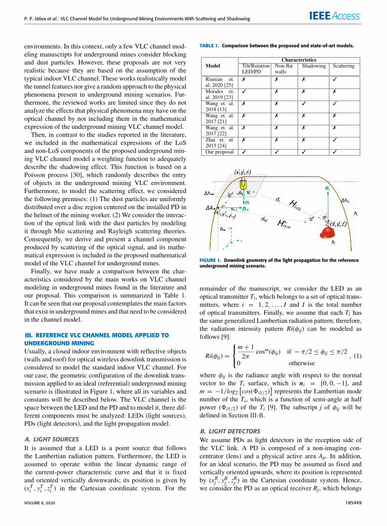
III. REFERENCE VLC CHANNEL MODEL APPLIED TOUNDERGROUND MININGUsually, a closed indoor environment with reflective objects(walls and roof) for optical wireless downlink transmission isconsidered to model the standard indoor VLC channel. Forour case, the geometric configuration of the downlink trans-mission applied to an ideal (referential) underground miningscenario is illustrated in Figure 1, where all its variables andconstants will be described below. The VLC channel is thespace between the LED and the PD and to model it, three dif-ferent components must be analyzed: LEDs (light sources),PDs (light detectors), and the light propagation model.
A. LIGHT SOURCESIt is assumed that a LED is a point source that followsthe Lambertian radiation pattern. Furthermore, the LED isassumed to operate within the linear dynamic range ofthe current-power characteristic curve and that it is fixedand oriented vertically downwards; its position is given by(xTi , y
Ti , z
Ti ) in the Cartesian coordinate system. For the
TABLE 1. Comparison between the proposed and state-of-art models.
FIGURE 1. Downlink geometry of the light propagation for the referenceunderground mining scenario.
remainder of the manuscript, we consider the LED as anoptical transmitter Ti, which belongs to a set of optical trans-mitters, where i = 1, 2, . . . , I and I is the total numberof optical transmitters. Finally, we assume that each Ti hasthe same generalized Lambertian radiation pattern; therefore,the radiation intensity pattern Ri(φij) can be modeled asfollows [9]:
Ri(φij) =
m+ 12π
cosm(φij) if − π/2 ≤ φij ≤ π/2
0 otherwise, (1)
where φij is the radiance angle with respect to the normalvector to the Ti surface, which is ni = [0, 0,−1], andm = −1/log2
[cos(8i1/2)
]represents the Lambertian mode
number of the Ti, which is a function of semi-angle at halfpower (8i1/2) of the Ti [9]. The subscript j of φij will bedefined in Section III-B.
B. LIGHT DETECTORSWe assume PDs as light detectors in the reception side ofthe VLC link. A PD is composed of a non-imaging con-centrator (lens) and a physical active area Ap. In addition,for an ideal scenario, the PD may be assumed as fixed andvertically oriented upwards, where its position is representedby (xRj , y
Rj , z
Rj ) in the Cartesian coordinate system. Hence,
we consider the PD as an optical receiver Rj, which belongs
VOLUME 8, 2020 185449

P. P. Játiva et al.: VLC Channel Model for Underground Mining Environments With Scattering and Shadowing
to a set of optical receivers where j = 1, 2, . . . , J and J isthe total number of optical receivers. Rj collects the incidentpower produced by the light intensity of Ti. The effectivecollection area of the Rj detector acquires the form of [9]
Aeff (θij) =
{Apcos(θij) if −2/2 ≤ θij ≤ 2/20 otherwise
, (2)
where θij is the incidence angle with respect to the normalvector to the Rj surface, which is nj = [0, 0, 1], and 2 is thePD field of view (FoV). The optical concentrator gain can bewritten as g(θij) = η2/sin2(2), being η the internal refractiveindex of the concentrator [9].
C. VISIBLE LIGHT PROPAGATION MODELIn Sections III-A and III-B, the mathematical models ofthe LEDs and PDs were introduced. Here, we use them toderive the reference VLC channel model. In general, the VLCchannel ismodeled based on two optical components: the LoScomponent and non-LoS component. The LoS componentdirectly results from the LED lighting falling on the PD.Therefore, the LoS link depends on LEDs and PDs param-eters as seen above. The direct current (DC) gain of the LoSoptical wireless channel is formulated by merging (1) and (2)by the following form [9]:
HLoS (0;Ti,Rj) =(m+ 1)Ap2πd2ij
cosm(φij) cos(θij)G(θij)
×rect(θij
2
), (3)
where rect(θij2
)= 1 for 0 ≤ θij ≤ 2 and 0 otherwise; the
Euclidean distance between Ti and Rj is denoted by dij, andG(θij) = Ts(θij) g(θij) represents the combined gain of theoptical filter and optical concentrator, respectively [9].
On the other hand, as a result of obstacles, indoor walland ceiling surfaces, a diffuse component of the transmittedlight is reflected by these elements. The sum of these reflec-tions generates the non-LoS component of the VLC channel,termed as HNLoS . A common model for diffuse reflectionis the Lambertian reflectance where light is reflected withequal radiance in all directions. This model is based on theparadigm that the component ‖H (k)
NLoS‖ → 0 when k →∞,where H (k)
NLoS is the non-LoS component after k bounces,and k is the total number of bounces [9], [16]. This conceptimplies two generalities: (1) Reflections caused by largenumber of bounces of k th order would be negligible. (2) Thefirst bounce comes to be the most important component thataffects the received power and its temporal dispersion. There-fore, theHNLoS component could be estimated by consideringthe first bounce, which is known as H (1)
NLoS .The DC gain of the non-LoS optical wireless channel can
be calculated by adding all the components arriving at the Rjafter being reflected in a surface, namely [9]
H (1)NLoS (0;Ti,Rj) =
(m+ 1)Ap2π
W∑w=1
1Awρwd2iwd
2wj
cosm(φiw)
×cos(θiw)cos(φwj) cos(θwj)G(θwj)
×rect(θwj
2
), (4)
where 1Aw denotes the wth area of the considered reflec-tive element w, whose reflection coefficient and position arerespectively represented by ρw and (xSw, y
Sw, z
Sw).W is the total
number of reflective elements considered in the scenario.The incidence angle with respect to the normal vector tothe reflective element w ( nw = [0, 1, 0]) and the radianceangle of the light component reaching the reflective elementw are symbolized with θiw and φiw, respectively. The anglesof incidence and radiance denoted by θwj and φwj respectivelyare measured with respect to the light component that isreflected in the reflective element w and reaches Rj. Finally,the Euclidean distances between Ti and the reflective elementw, and between the reflective element w and Rj are given bydiw and dwj, respectively.As we mentioned, the analysis of VLC system compo-
nents that we present in this section focuses on a referenceVLC channel model. Therefore, despite applying it to atunnel, we do not consider intrinsic factors and features ofthe underground mine. However, this observation gives us aoverall framework and naturally leads us to Sections IV, Vand VI, where we discuss more details about the developmentof the proposed underground mining VLC channel model.In Section IV we analyze and consider in the undergroundmining VLC channel model to be proposed, the position char-acteristics (rotation and tilt) of the system elements (LEDsand PDs), and the effect of the non-regular and non-flat wallsof the tunnels. Then, in Section V, we statistically character-ize the shadowing and add it to the VLC underground miningchannel components derived in Section IV. The scatteringdistribution in the underground mining scenario, its statisticalcharacterization, and its channel component are derived inSectionVI. At the end of this section, the closedmathematicalexpression of the proposed undergroundminingVLC channelmodel is presented.
IV. POSITION CHARACTERIZATION OF LEDs AND PDs,AND NON-FLAT WALLS MODELINGA. TILTED AND ROTATED LEDs AND PDsIn a real underground mining scenario, LED luminaries arenormally installed on the ceiling or on thewalls of the tunnels.To facilitate maintenance and replacement work, the place-ment of LEDs in the curved sections between the wall andthe ceiling of the tunnel is preferred. When we place theTi on the tunnel walls, it normally does not point verticallydownwards. A convenient way to describe the orientation ofthe Ti is to use two separate angles that show the tilt androtation on the axes of the reference coordinate system. Thetilt angle with respect to the z-axis is represented by βi, whichtakes values in range of [90◦, 180◦) and the rotation anglewith respect to the x-axis is denoted as αi, which is definedin the interval [0◦, 360◦). Both ranges of values are based onthe characteristics of the underground mining scenario and
185450 VOLUME 8, 2020
P. P. Játiva et al.: VLC Channel Model for Underground Mining Environments With Scattering and Shadowing
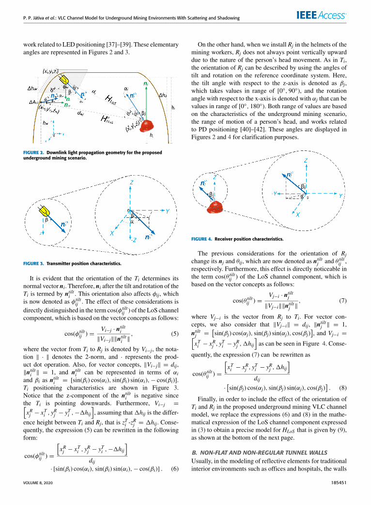
work related to LED positioning [37]–[39]. These elementaryangles are represented in Figures 2 and 3.
FIGURE 2. Downlink light propagation geometry for the proposedunderground mining scenario.
FIGURE 3. Transmitter position characteristics.
It is evident that the orientation of the Ti determines itsnormal vector ni. Therefore, ni after the tilt and rotation of theTi is termed by ntilti . This orientation also affects φij, whichis now denoted as φtiltij . The effect of these considerations isdirectly distinguished in the term cos(φtiltij ) of the LoS channelcomponent, which is based on the vector concepts as follows:
cos(φtiltij ) =Vi−j · ntilti‖Vi−j‖‖ntilti ‖
, (5)
where the vector from Ti to Rj is denoted by Vi−j, the nota-tion ‖ · ‖ denotes the 2-norm, and · represents the prod-uct dot operation. Also, for vector concepts, ‖Vi−j‖ = dij,‖ntilti ‖ = 1, and ntilti can be represented in terms of αiand βi as ntilti = [sin(βi) cos(αi), sin(βi) sin(αi),− cos(βi)].Ti positioning characteristics are shown in Figure 3.Notice that the z-component of the ntilti is negative sincethe Ti is pointing downwards. Furthermore, Vi−j =[xRj − x
Ti , y
Rj − y
Ti ,−1hij
], assuming that 1hij is the differ-
ence height between Ti and Rj, that is zTi -zRj = 1hij. Conse-
quently, the expression (5) can be rewritten in the followingform:
cos(φtiltij ) =
[xRj − x
Ti , y
Rj − y
Ti ,−1hij
]dij
· [sin(βi) cos(αi), sin(βi) sin(αi),− cos(βi)] . (6)
On the other hand, when we install Rj in the helmets of themining workers, Rj does not always point vertically upwarddue to the nature of the person’s head movement. As in Ti,the orientation of Rj can be described by using the angles oftilt and rotation on the reference coordinate system. Here,the tilt angle with respect to the z-axis is denoted as βj,which takes values in range of [0◦, 90◦), and the rotationangle with respect to the x-axis is denoted with αj that can bevalues in range of [0◦, 180◦). Both range of values are basedon the characteristics of the underground mining scenario,the range of motion of a person’s head, and works relatedto PD positioning [40]–[42]. These angles are displayed inFigures 2 and 4 for clarification purposes.
FIGURE 4. Receiver position characteristics.
The previous considerations for the orientation of Rjchange its nj and θij, which are now denoted as ntiltj and θ tiltij ,respectively. Furthermore, this effect is directly noticeable inthe term cos(θ tiltij ) of the LoS channel component, which isbased on the vector concepts as follows:
cos(θ tiltij ) =Vj−i · ntiltj‖Vj−i‖‖ntiltj ‖
, (7)
where Vj−i is the vector from Rj to Ti. For vector con-cepts, we also consider that ‖Vj−i‖ = dij, ‖ntiltj ‖ = 1,ntiltj =
[sin(βj) cos(αj), sin(βj) sin(αj), cos(βj)
], and Vj−i =[
xTi − xRj , y
Ti − y
Rj ,1hij
]as can be seen in Figure 4. Conse-
quently, the expression (7) can be rewritten as
cos(θ tiltij ) =
[xTi − x
Rj , y
Ti − y
Rj ,1hij
]dij
·[sin(βj) cos(αj), sin(βj) sin(αj), cos(βj)
]. (8)
Finally, in order to include the effect of the orientation ofTi and Rj in the proposed underground mining VLC channelmodel, we replace the expressions (6) and (8) in the mathe-matical expression of the LoS channel component expressedin (3) to obtain a precise model for HLoS that is given by (9),as shown at the bottom of the next page.
B. NON-FLAT AND NON-REGULAR TUNNEL WALLSUsually, in the modeling of reflective elements for traditionalinterior environments such as offices and hospitals, the walls
VOLUME 8, 2020 185451

P. P. Játiva et al.: VLC Channel Model for Underground Mining Environments With Scattering and Shadowing
are considered as ideal reflective elements. Among the idealfeatures assumed can be mentioned: perpendicularity withrespect to the ceiling, regularity, and flat surface. However,these assumptions do not make sense in underground minessince most tunnels are U-shaped, irregular, and non-flat.Therefore, it is necessary to adequately model the effect ofthe tunnel walls to include them in the proposed undergroundmining VLC channel model and analyze their impact onsystem performance.
As mentioned in Section III-C, each reflective element ismodeledwith the Lambertian reflectance, so each of them canbe considered as a Lambertian point source. However, in theunderground mining context, the irregularity of the surfaceof each reflective element implies that the radiation intensityof this source and the direction of the reflected light are notdeterministic. Additionally, in ideal reflective elements, theirnormal vectors are orthogonal to their surfaces and everyonepointing in the same direction. This situation does not occur ina underground mining scenario. Here, each reflective elementhas an irregular surface. Therefore, their normal vectors arenot orthogonal to their surface, and they point in differentdirections.
As happened with the normal vectors described inSection IV-A, the normal vector nw of each reflective elementw can be described in terms of their tilt and rotation angleson the axes of the reference coordinate system. Here, the tiltangle with respect to the z-axis is denoted as βw, whichbelongs to the range of [0◦, 180◦) and the rotation angle withrespect to the x-axis is denoted as αw and takes values in rangeof [0◦, 180◦). Both intervals are based on the characteristicsand limitations that exist in a underground mining scenario(see Figure 2).
The introduced features for the orientation of each reflec-tive elementw changes its normal vector nw, and its angles θiwand φwj, which are now termed by ntiltw , θ tiltiw and φtiltwj , respec-tively. Additionally, the tilt and rotation of Ti and Rj affectsthis channel component in terms of the angles φiw and θwj,which are redefined by φtiltiw and θ tiltwj , respectively. Therefore,the irregular walls of the tunnels along with the orientationof Ti and Rj directly affect the non-LoS component of theunderground mining VLC channel.
The effect of these considerations is noticeable in termsof the following cosines: cos(φtiltiw ), cos(θ tiltiw ), cos(φtiltwj ) andcos(θ tiltwj ) in the following form:
cos(φtiltiw ) =Vi−w · ntilti‖Vi−w‖‖ntilti ‖
, (10)
where Vi−w is the vector from Ti to w, ‖Vi−w‖ = diw, andVi−w =
[xSw − x
Ti , y
Sw − y
Ti ,−1hiw
], assuming that 1hiw is
the difference height between Ti and w.
cos(θ tiltiw ) =Vw−i · ntiltw‖Vw−i‖‖ntiltw ‖
, (11)
where Vw−i is the vector from w to Ti, ‖Vw−i‖ = diw,‖ntiltw ‖ = 1, ntiltw can be represented in terms of αw and βw,that is ntiltw = [sin(βw) cos(αw), sin(βw) sin(αw), cos(βw)] andVw−i =
[xTi − x
Sw, y
Ti − y
Sw,1hiw
].
cos(φtiltwj ) =Vw−j · ntiltw‖Vw−j‖‖ntiltw ‖
, (12)
where Vw−j is the vector from w to Rj, ‖Vw−j‖ = dwj, and
Vw−j =[xRj − x
Sw, y
Rj − y
Sw,−1hwj
], assuming that 1hwj is
the difference height between w and Rj.
cos(θ tiltwj ) =Vj−w · ntiltj‖Vj−w‖‖ntiltj ‖
, (13)
where Vj−w is the vector from Rj to w, ‖Vj−w‖ = dwj, and
Vj−w =[xSw − x
Rj , y
Sw − y
Rj ,1hwj
].
All the previous definitions allow us to reform the expres-sions (10), (11), (12), and (13). Finally, in order to includethe effect of non-regular walls of the tunnels in the proposedunderground mining VLC channel model, we replace thesenew expressions in the mathematical model of the non-LoSchannel component expressed in (4). As a consequence,we obtain an exact expression for H (1)
NLoS given by (14), asshown at the bottom of the next page.
V. STATISTICAL SHADOWING MODEL CAUSED BYRANDOM OBSTRUCTIONSA physical phenomenon that particularly conditions wirelesscommunication links in underground mining environments isthe shadowing due to its great dependence on having line ofsight, by affecting the system performance. Because of theunderground mining infrastructure, in which there are largemachinery and vehicles that move by the tunnels, the effect ofshadowing must be considered in order to derive a reasonableunderground mining VLC channel model.
In our shadowing study, we are assuming that the PD ismounted on theminers’ helmet. Therefore, due to the locationof Ti, we do not consider the shadowing effect that couldoccur when miners (human obstacles) block the VLC link.Because of the real characteristics of the tunnels, we only
HLoS (0;Ti,Rj) =(m+ 1)Ap2πdm+3ij
{[xRj − x
Ti , y
Rj − y
Ti ,−1hij
]· [sin(βi) cos(αi), sin(βi) sin(αi),− cos(βi)]
}m×
{[xTi − x
Rj , y
Ti − y
Rj ,1hij
]·[sin(βj) cos(αj), sin(βj) sin(αj), cos(βj)
]}G(θ tiltij )rect
(θ tiltij
2
)(9)
185452 VOLUME 8, 2020

P. P. Játiva et al.: VLC Channel Model for Underground Mining Environments With Scattering and Shadowing
consider the optical link blockage caused by vehicles andobstacles moving along the tunnels.
A. ASSUMPTIONS CONSIDERED TO MODEL SHADOWINGSTATISTICALLYShadowing comes from non-quantitative obstructions (vehi-cles and obstacles) that randomly enter to the undergroundmining area with particular characteristics (size, position,income intensity, etc.). In addition, we consider that numer-ous LEDs illuminate the work area in underground minescompletely. Therefore, it is impossible for all optical linksto be completely blocked. However, vehicles entering theunderground mining area can block certain optical links andpartially attenuate the transmitted signal strength.
According to the literature, shadowing applied to VLCsystems has been modeled as a binomial Gaussian distribu-tion [13] and as a Poisson process [30]. After a comparativeanalysis of models that fit the real characteristics of theshadowing phenomenon in underground mines, we followand extrapolate to our analysis a statistical methodology forshadowing modeling [30]. This approach utilizes a Poissonprocess to describe the appearance of obstructions in the VLCenvironment, a probability density function to characterizethe size and position of the obstructions, such as vehicles orheavy machinery, and a weighting function to describe theshadowing effect. The weighting function will be describedin detail and derived in Section V-C.
B. DESCRIPTION OF THE UNDERGROUND MININGSCENARIO WITH OPTICAL LINK BLOCKINGWe consider a VLC link obstruction/non-obstruction under-ground mining scenario as shown in Figure 5. In order toeasily represent the underground mining environment andwithout losing the generality, we assume that the tunnel areato be analyzed is cubic with the following dimensions: length(X), width (Y), and height (Z). For a better description of thescenario, we consider a line segment AB, where the point A isthe Cartesian coordinate where Ti is located and the point B isthe Cartesian coordinate where Rj is located. We observe thatthe magnitude of line segment AB matches to the magnitudeof dij.
For our model, we discard the thickness of the obstruc-tion and consider the point V , whose coordinates are repre-sented by (xv, yv, 0), as the midpoint of the projection of the
FIGURE 5. Schematic diagram of the AB optical link being blocked by amobile obstruction with width wv and height hv .
obstruction in the x-y plane. Furthermore, the line segmentCD represents the projection of line segment AB in thex-y plane, whose coordinates of the points C and D are(xTi , y
Ti , 0), (x
Rj , y
Rj , 0) respectively. Finally, we consider a
perpendicular line segment to CD from the point (xv, yv, 0)with the point E being the foot point and, thus, we construct aline EF parallel to the z-axis through point E, where the pointF denotes the intersecting point with the segment AB.
C. PROPOSED STATISTICAL SHADOWING MODELBased on the work presented in [30], we statistically modelthe entry of obstructions into the underground mining envi-ronment and, consequently, the shadowing produced consid-ering the following statistical assumptions: (1) We assumethat there are not obstructions in the scenario at the beginningtime. (2) For the no-shadowed case, VLC channel compo-nents are not affected. On the other hand, for the shadowedsituation, a weighting function Pij is introduced to describethe random shadowing. Pij describes the probability thatthe LoS optical link is not blocked. (3) We assume theentry of obstructions to the underground mining area as aPoisson process Nt with an intensity parameter ε. Further-more, each obstruction is independently and identically dis-tributed with its own dimensions (width wo and height ho)and position (xo, yo). Therefore, the blocking or not of theoptical link that the obstacles can cause are independentof each other. (4) We denote possible obstructions enteringthe scenario within a period of time t as (w1, h1, x1, y1),(w2, h2, x2, y2),. . . ,(wNt , hNt , xNt , yNt ). (5) We denote pv as
H (1)NLoS (0;Ti,Rj) =
(m+ 1)Ap2π
W∑w=1
1Awρwdm+3iw d4wj
{[xSw − x
Ti , y
Sw − y
Ti ,−1hiw
]· [sin(βi) cos(αi), sin(βi) sin(αi),− cos(βi)]
}m×
{[xTi − x
Sw, y
Ti − y
Sw,1hiw
]· [sin(βw) cos(αw), sin(βw) sin(αw), cos(βw)]
}×
{[xRj − x
Sw, y
Rj − y
Sw,−1hwj
]· [sin(βw) cos(αw), sin(βw) sin(αw), cos(βw)]
}×
{[xSw − x
Rj , y
Sw − y
Rj ,1hwj
]·[sin(βj) cos(αj), sin(βj) sin(αj), cos(βj)
]}G(θ tiltwj )rect
(θ tiltwj
2
). (14)
VOLUME 8, 2020 185453

P. P. Játiva et al.: VLC Channel Model for Underground Mining Environments With Scattering and Shadowing
the probability that the LoS optical link (line segment AB) isblocked by (wv, hv, xv, yv) where v takes values from 1 to Ntand p1, p2,. . . , pNt are independent and identically distributed.Consequently, Pij can be written as [30]
Pij = exp [−εE(pv)t], (15)
where E(pv) is the expected value of pv. Now, we must findthe specific physical and geometric conditions that mathe-matically demonstrate when the optical link is blocked bysome obstruction (wv, hv, xv, yv). Based on the geometryof Figure 5, we can summarize two main conditions [30]:(1) Half of wv must be greater than or equal to the distancefrom the point (xv, yv) to the segment CD, namely wv/2 ≥d(xv, yv). (2) hv must be greater than or equal to the length ofEF, namely hv ≥ s(xv, yv).Since the coordinates of the points A and B are known,
we can formulate the expressions of d(xv, yv) and s(xv, yv) asfollows:
d(xv, yv) =|(yTi − y
Rj )xv − (xTi − x
Rj )yv − x
Rj y
Ti + x
Ti y
Rj |√
(yTi − yRj )
2 + (xTi − xRj )
2,
(16)
s(xv, yv) =(yTi − y
Rj )
2+ (xTi − x
Rj )
2+ (xv − xRj )
2
2√(yTi − y
Rj )
2 + (xTi − xRj )
2
+(yv − yRj )
2− [(xv − xTi )
2+ (yv − yTi )
2]
2√(yTi − y
Rj )
2 + (xTi − xRj )
2+ zRj .
(17)
As the entry of possible obstructions to the tunnel is notdeterministic, we denote functions of joint probability den-sity for wv and hv as gv(w, h) and for xv and yv as fv(x, y),respectively. It is worth noting that these joint probabilitydensity functions can be adapted and chosen depending onthe actual situation of the scenario to be modeled, in our case,the underground mining scenario. Consequently, E(pv) andPij are presented in [30], (18) and (19), as shown at the bottomof the page.
Finally, we include the shadowing characterization andits effect in the LoS channel component expressed in (9)by including the weighted function Pij in its mathematicalexpression. In addition, we also consider the shadowing effectin the non-LoS channel component expressed in (14) byincluding the weighted functions Piw and Pwj in its mathe-matical expression. These weighted functions are obtainedthrough the same statistical process to obtain Pij and theyrepresent possible blockages in the optical link between Ti
and the reflective element w, and the optical link between wand Rj, respectively. Therefore, the newmathematical expres-sions obtained by multiplying the LoS an non-LoS channelcomponents by their corresponding weighting function aredenoted as HLoS(sh) and H
(1)NLoS(sh)
respectively, and expressedas follows:
HLoS(sh) (0;Ti,Rj) = HLoS (0;Ti,Rj)Pij, (20)
H (1)NLoS(sh)
(0;Ti,Rj) = H (1)NLoS (0;Ti,Rj)PiwPwj. (21)
VI. STATISTICAL SCATTERING MODEL PRODUCEDBY DUST PARTICLESIn general, the scattering produced by the suspended dustis generally despicable in traditional indoor environments,such as offices, hospitals, or non-dangerous industries. There-fore, in these scenarios, VLC systems are not generallyaffected by dust particles. Instead, in underground mines,large amounts of dust are originated by crushing, grinding,flying, and drilling the rock within the mine. Hence, it isnecessary to model the scattering effect and introduce it intothe underground mining VLC channel model. Consequently,we perform an in-depth analysis to derive the appropriatemathematical model that fits this physical phenomenon.
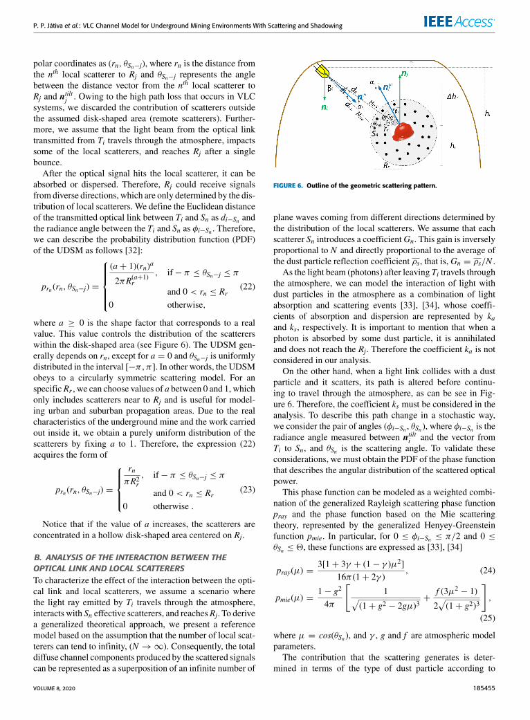
We propose an stochastic model that provides a simplephysical interpretation, but in accordance with the real char-acteristics of the underground mining scenarios. The modelthat we introduce is based on the theory of absorption anddispersion of photons that travel through the atmosphere.Also, we model the distribution of the scatterers elements(dust particles) based on the unified disk scattering model(UDSM), which is revealed in [32]. This model allows usto control the distribution of the scatterers by using a factor,which controls the concentration pattern of the scatterers.
A. SCATTERERS DISTRIBUTION MODEL CONSIDERATIONSThe outline of the scatterers distribution, as well as the geo-metric considerations that we adopt in our analysis are dis-played in Figure 6. By considering the underground miningenvironment, we assume that at the beginning, Ti is free ofscatterers to their surroundings and the height where theyare positioned is greater than the height where Rj is located.Furthermore, we assume that the scatterers are randomly andindependently distributed within a disk-shaped area of radioRr centered on Rj. These scatterers are called local scatterers.
We consider that within the disk centered on Rj, thereare numerous local scatterers Sn, where n = 1, 2, . . . ,N .Theoretically, the number of scatters N could tend to infinite.The location of each local scatterer is represented by its
E(pv) =∫ X
0
∫ Y
0
[∫ ∫{(w,h):w≥2d(x,y),h≥s(x,y)}
gv(w, h)dw dh]fv(x, y)dx dy, (18)
Pij = exp{−ε
{∫ X
0
∫ Y
0
[∫ ∫{(w,h):w≥2d(x,y),h≥s(x,y)}
gv(w, h)dw dh]fv(x, y)dx dy
}t}. (19)
185454 VOLUME 8, 2020
P. P. Játiva et al.: VLC Channel Model for Underground Mining Environments With Scattering and Shadowing
polar coordinates as (rn, θSn−j), where rn is the distance fromthe nth local scatterer to Rj and θSn−j represents the anglebetween the distance vector from the nth local scatterer toRj and ntiltj . Owing to the high path loss that occurs in VLCsystems, we discarded the contribution of scatterers outsidethe assumed disk-shaped area (remote scatterers). Further-more, we assume that the light beam from the optical linktransmitted from Ti travels through the atmosphere, impactssome of the local scatterers, and reaches Rj after a singlebounce.
After the optical signal hits the local scatterer, it can beabsorbed or dispersed. Therefore, Rj could receive signalsfrom diverse directions, which are only determined by the dis-tribution of local scatterers. We define the Euclidean distanceof the transmitted optical link between Ti and Sn as di−Sn andthe radiance angle between the Ti and Sn as φi−Sn . Therefore,we can describe the probability distribution function (PDF)of the UDSM as follows [32]:
prn (rn, θSn−j) =
(a+ 1)(rn)a
2πR(a+1)r, if− π ≤ θSn−j ≤ π
and 0 < rn ≤ Rr0 otherwise,
(22)
where a ≥ 0 is the shape factor that corresponds to a realvalue. This value controls the distribution of the scattererswithin the disk-shaped area (see Figure 6). The UDSM gen-erally depends on rn, except for a = 0 and θSn−j is uniformlydistributed in the interval [−π , π ]. In other words, the UDSMobeys to a circularly symmetric scattering model. For anspecificRr , we can choose values of a between 0 and 1, whichonly includes scatterers near to Rj and is useful for model-ing urban and suburban propagation areas. Due to the realcharacteristics of the underground mine and the work carriedout inside it, we obtain a purely uniform distribution of thescatterers by fixing a to 1. Therefore, the expression (22)acquires the form of
prn (rn, θSn−j) =
rnπR2r
, if− π ≤ θSn−j ≤ π
and 0 < rn ≤ Rr0 otherwise .
(23)
Notice that if the value of a increases, the scatterers areconcentrated in a hollow disk-shaped area centered on Rj.
B. ANALYSIS OF THE INTERACTION BETWEEN THEOPTICAL LINK AND LOCAL SCATTERERSTo characterize the effect of the interaction between the opti-cal link and local scatterers, we assume a scenario wherethe light ray emitted by Ti travels through the atmosphere,interacts with Sn effective scatterers, and reachesRj. To derivea generalized theoretical approach, we present a referencemodel based on the assumption that the number of local scat-terers can tend to infinity, (N →∞). Consequently, the totaldiffuse channel components produced by the scattered signalscan be represented as a superposition of an infinite number of
FIGURE 6. Outline of the geometric scattering pattern.
plane waves coming from different directions determined bythe distribution of the local scatterers. We assume that eachscatterer Sn introduces a coefficientGn. This gain is inverselyproportional to N and directly proportional to the average ofthe dust particle reflection coefficient ρs, that is, Gn = ρs/N .As the light beam (photons) after leaving Ti travels through
the atmosphere, we can model the interaction of light withdust particles in the atmosphere as a combination of lightabsorption and scattering events [33], [34], whose coeffi-cients of absorption and dispersion are represented by kaand ks, respectively. It is important to mention that when aphoton is absorbed by some dust particle, it is annihilatedand does not reach the Rj. Therefore the coefficient ka is notconsidered in our analysis.
On the other hand, when a light link collides with a dustparticle and it scatters, its path is altered before continu-ing to travel through the atmosphere, as can be see in Fig-ure 6. Therefore, the coefficient ks must be considered in theanalysis. To describe this path change in a stochastic way,we consider the pair of angles (φi−Sn , θSn ), where φi−Sn is theradiance angle measured between ntilti and the vector fromTi to Sn, and θSn is the scattering angle. To validate theseconsiderations, we must obtain the PDF of the phase functionthat describes the angular distribution of the scattered opticalpower.
This phase function can be modeled as a weighted combi-nation of the generalized Rayleigh scattering phase functionpray and the phase function based on the Mie scatteringtheory, represented by the generalized Henyey-Greensteinfunction pmie. In particular, for 0 ≤ φi−Sn ≤ π/2 and 0 ≤θSn ≤ 2, these functions are expressed as [33], [34]
pray(µ) =3[1+ 3γ + (1− γ )µ2]
16π (1+ 2γ ), (24)
pmie(µ) =1− g2
4π
[1√
(1+ g2 − 2gµ)3+
f (3µ2− 1)
2√(1+ g2)3
],
(25)
where µ = cos(θSn ), and γ , g and f are atmospheric modelparameters.
The contribution that the scattering generates is deter-mined in terms of the type of dust particle according to
VOLUME 8, 2020 185455

P. P. Játiva et al.: VLC Channel Model for Underground Mining Environments With Scattering and Shadowing
its diameter. This contribution is governed by atmosphericcomposition and modeled by the weighting parameters krand km, which are Rayleigh scattering and Mie scatteringcoefficients, respectively. In addition, we know that ks =kr + km [33], [34]. The interaction of these phase functionsfollows a Bernoulli distribution, i.e. the probability that thephoton is modeled as pray is kr /ks and the probability thatthe photon is modeled as pmie is km/ks. Therefore, the over-all phase function along with its respective PDF is givenby [33], [34]
ptotal(µ) =krkspray(µ)+
kmkspmie(µ), (26)
fsca(µ) = ptotal(µ) sin (µ). (27)
Finally, Gn is redefined as Gn(µ) = ρsfsca(µ)/N .
C. PROPOSED CHANNEL MODEL CONSIDERING THEEFFECTS OF SCATTERINGBased on the mathematical expression of the typical Lamber-tian channel model, we present the channel model producedby scattering on the optical path Ti-Sn-Rj, which correspondsto the light beam that travels from Ti, interacts with the localscatterrer Sn and reaches Rj. In this context, the DC gainmathematical expression of the scattering optical wirelesschannel can be written as
Hsca(0;Ti, Sn,Rj) = limN→∞
N∑n=1
Ap(m+ 1)Gn(µ)
2πD2i−n−j
× cosm(φi−Sn ) cos(θSn−j)rect(θSn−j
2
),
(28)
where the path lengthDi−n−j represents the total distance thatlight travels from the Ti via Sn to the Rj and can be expressedas Di−n−j = di−Sn + rn. Furthermore, based on the geometryof the Figure 6, the expression di−Sn can be determined byusing the law of cosines as follows:
di−Sn =√r2n + d
2ij − 2rndij cos (βi−Sn ), (29)
where βi−Sn denotes the difference between the angles θi−Snand θ tiltij . The value of βi−Sn depends on the value of theseangles and the position of the Sn in the following form:
βi−Sn =
{θSn−j − θ
tiltij if θ tiltij < θSn−j
θ tiltij − θSn−j otherwise. (30)
To conclude, we now present the general expression ofthe proposed underground mining VLC channel DC gain asfollows:
Hminer (0;Ti,Rj) = HLoS(sh) (0;Ti,Rj)+ H(1)NLoS(sh)
(0;Ti,Rj)
+Hsca(0;Ti, Sn,Rj). (31)
The general expression of the underground mining VLCchannel model is formed by the addition of expressions (20),(21), and (28). Therefore, we fulfill the objective of includingin a single expression all the intrinsic factors of the under-ground mining scenarios.
VII. RESULTS AND ANALYSISIn this section, we simulate the CIR, RMS delay spread, andreceived power based on the proposed underground miningVLC channel model. For the simulation, we choose a tunnelsection of dimensions 6m × 3m × 5m. In our analysis, butwithout losing the generality, we consider a single transmitterand a single receiver, T1 and R1, respectively. R1 is installedon the helmet of mining workers. For a better comparison ofthe results, an ideal (reference) underground mining scenarioand a more realistic (proposed) underground mining scenarioare simulated, where the reference VLC channel model andthe proposed VLC channel model are included, respectively.These scenarios and their parameters are specified in Table 2.Other system parameters are listed in Table 3.
TABLE 2. Parameters for the underground mining simulation scenarios.
As the benchmark situation, a reference underground min-ing scenario is simulated and then compared to the proposedunderground mining scenario to discuss and highlight theirdifferences. As mentioned in Section III, the ideal scenarioonly considers the LoS channel component and the non-LoScomponents produced by reflections in the walls. Here, twowalls are considered to represent the side walls of the tunnel,which are assumed flat and regular. T1 is installed pointingdownwards and R1 is installed pointing upwards, both locatedin fixed positions on the tunnel. Finally, in this scenario,neither the shadowing effect nor the scattering effect areconsidered.
185456 VOLUME 8, 2020

P. P. Játiva et al.: VLC Channel Model for Underground Mining Environments With Scattering and Shadowing
TABLE 3. System parameters.
Instead, in the proposed underground mining scenario,we consider five different positions of R1 in the tunnel. Theselocations represent the most likely positions that miningworkers could have in the tunnel according to their generalwork area. It should be emphasized that these positions arereferential since we assume a single LED and a fixed PDposition only to verify the feasibility of the proposed VLCchannel model. Generally in underground mines, distributedLED array lighting sources composed of several LEDs areused. In addition, multiple of these LED arrays are distributedthroughout the tunnel. Therefore, we would only need super-pose all the solutions induced by each LED in order to get theanalysis of the total tunnel. Due to the considered characteris-tics of the proposed underground mining scenario, no matterwhere R1 is located, the proposed VLC channel model wouldwork in the same way.
The positions of R1 are graphically described in Figure 7.For illustrative purposes in all positions, R1 is tilted androtated, and its angles of tilt (βj) and rotation (αj) are both 45◦.Two walls are considered to represent the side walls of thetunnel, which are non-flat and non-regular. This effect isconsidered in βw and αw, which follow a uniform probabilitydistribution, βw ∼U [0,180◦] and αw ∼U [0,180◦]. The effectof shadowing is considered with obstructions entering thetunnel and following the Poisson process described in theSection V, whose intensity parameter ε is 5 per minute.Furthermore, for simplicity and model illustration, we con-sider that the joint probability density functions fv(x, y) andgv(w, h) follow a uniform distribution, fv(x, y)∼U [0,25] andgv(w, h) ∼ U [0,2]. The scattering effect is considered by
FIGURE 7. Proposed simulation scenario for five different positions of R1.
including local scatterers that follow the distribution detailedin Section VI. The number of local scatterers (N ) is set at40 [35], [36]. The analysis of this value and its variations iscarried out in Section VII-A2.
A. ANALYSIS OF THE PROPOSED UNDERGROUNDMINING CHANNEL IMPULSE RESPONSETo evaluate the derived underground mining VLC channelmodel and confirm the accuracy of our approach, we presentthe CIRs for the five positions of R1. These CIRs, eachrepresented by hminer (t;Ti,Rj) are defined as the receivedoptical intensity when the transmitted optical intensity isa unit-area Dirac delta function. Therefore hminer (t;Ti,Rj)can be obtained from expression (31), by adding the deltacomponents δ(·) that depend on the distance the light beamtravels as follows:
hminer (t;Ti,Rj)
= hLoS(sh)(t;Ti,Rj)δ(t −
dijc
)+h(1)NLoS(sh)(t;Ti,Rj)
W∑w=1
δ
(t −
diw + dwjc
)
+hsca(t;Ti, Sn,Rj)N∑n=1
δ
(t −
Di−n−jc
). (32)
Given a number of rays including LoS, non-LoS, andscattering, we compute the detected power and path lengthsfrom T1 to R1 for each ray. Then, these data are processed toproduce the CIRs. To compare the results of the CIR, we findit convenient to assume that the transmitted power is 1 W.
Figure 8 shows the CIRs for the five positions of R1 inthe proposed underground mining scenario. The number ofpartitions is set to 18 for X and Y, and 15 for Z. The spacialresolution is set to 0.33 m for X and Z, and 0.16 m forY. The temporal resolution is set to 0.25 ns (see Table 2).The distance represented in the Figure 8 is the referential
VOLUME 8, 2020 185457

P. P. Játiva et al.: VLC Channel Model for Underground Mining Environments With Scattering and Shadowing
FIGURE 8. CIRs of the five R1 positions in the evaluated undergroundmining scenario.
Euclidean distance between T1 and R1. We observed in all R1positions that the LoS component has a higher contribution inthe CIR compared to the non-LoS and scattering components.However, the non-LoS and scattering components tend to adda significant amount of power to the total CIR. Furthermore,these components arrive later than the LoS component.
If we compare the CIRs in the Figure 8, several inter-esting findings can be distinguished. Firstly, as the distancebetween T1 and R1 increases, the underground mining CIRdecreases and its propagation delay increases, as well asthe rising edge of the CIR becomes less abrupt. However,we note that although the distance from position 3 of R1is less than the distance from positions 4 and 5, the CIRof position 3 is the smallest. This behavior occurs becausethe effect of shadowing is greater in that scenario due tothe position of R1. In this position, the optical link is morelikely to be partially or totally blocked due to the physi-cal characteristics of the obstructions entering the tunnel.Secondly, the results show that the obstructions affect allunderground mining scenarios. However, the position leastaffected by shadowing is the position 1 due to the proximityof R1 to T1. It is important to mention that both the LoScomponent and the non-LoS components are affected byshadowing.
1) CHANNEL IMPULSE RESPONSE PRODUCED BY NON-LOSCOMPONENTSTo develop an in-depth analysis of each channel componentthat contributes to the underground mining CIR, Figure 9shows the CIRs of the sum of all the non-LoS components ofthe five positions of R1. These CIRs in all the scenarios main-tain the trend of the total CIRs, that is, the greater the distancebetween T1 and R1, the smaller the magnitude of the CIRand the longer the propagation time. We also note that dueto bouncing on the walls, the non-LoS component travels agreater distance since leaving T1 compared to the distance the
FIGURE 9. CIRs considering the sum of the non-LoS components of thefive positions of R1 in the evaluated underground mining scenario.
LoS component travels. Therefore, the non-LoS componentsarrive at R1 with a longer delay than the LoS component. Theeffect of non-flat walls by having uniform random αw andβw in a specific interval causes non-LoS components of vari-ous magnitudes without marking an increasing or decreasingtrend with respect to time. On the other hand, we note thatshadowing directly affects non-LoS components dependingon the location of R1. This factor makes the position 1 theleast affected and the position 3 the most affect, even thoughthe latter has a shorter distance between T1 and R1 comparedto positions 4 and 5.
2) CHANNEL IMPULSE RESPONSE PRODUCED BYSCATTERING COMPONENTSTo analyze the channel components produced by scattering,Figure 10 illustrates the CIRs produced by scattering in thefive positions of R1 for the proposed underground miningscenario. It is possible to notice that although each positionincreases the distance between T1 and R1, the magnitudeof the CIR is not drastically decreased among R1 positions.In fact, it is observed that the maximum magnitudes of theCIRs of position 1 and 2 are approximately equal, as wellas the maximum magnitudes of positions 3, 4 and 5, withslight differences. This effect is because each local scatterfollows the UDSM distribution. Therefore, since the positionof the local scatter with respect to R1 is random, the distancebetween the local scatter and T1 will also be variable, so theCIRwill not depend solely on the distance between T1 andR1.Furthermore, we consider a gain (Gn) that depends on a gen-eral phase function gain that randomly combines Rayleighand Mie scattering, which directly influences similar magni-tudes between scenarios.
On the other hand, we note that when the distance betweenT1 and R1 increases, the scattering components reach R1later, maintaining the same trend as the LoS and non-LoScomponents. However, if we compare the arrival times per
185458 VOLUME 8, 2020

P. P. Játiva et al.: VLC Channel Model for Underground Mining Environments With Scattering and Shadowing
FIGURE 10. CIRs of the scattering components for the five positions of R1in the evaluated underground mining scenario.
position of the non-LoS CIRs (Figure 9) with the arrival timesper position of the scattering CIRs (Figure 10), we observethat for scattering they are lower. This is due to two factors:1) We only consider the optical path that starts from T1,bounces off the local scatterer and reaches R1. Therefore,the distance that the optical signal travels is less comparedto the distance of the optical path starting from T1 goingto the wall and reaching R1. 2) Since the local scatters aremuch closer to R1 (disk-shaped area), the signal bounce inthe local scatter would reach R1 faster if we compare it withthe proximity of the wall with R1. Finally, we can deducethat due to the size of the local scatterers (dust particles)the magnitude of the scatterer CIRs in all the positions issmaller compared to the CIRs non-LoS and LoS. However,this magnitude is not negligible and contributes with a factorof the total mining CIR.
For illustrative purposes, and to analyze the effect of thevariation and amount of local scatterers, we only choose posi-tion 1 of R1 and vary its values of N as can seen in Figure 11.We can notice that with values of N = 20 and N = 40,the maximum magnitude of the CIR remains approximatelythe same. Furthermore, with these values of N , the CIRreaches the maximum values in comparison with the othervalues of N . As the value of N decreases, the magnitudeof the CIR also decrease. This is because the gain factor(Gn) in the CIR is inversely proportional to N . Although wetheoretically assume that N→∞ (see expression (28)), notall optical signal bounces in local scatterers and reach R1.This would depend on the optical signal being inside the FoVof R1. Therefore, with this analysis, we can verify that thevalue of N (N = 40) chosen for all the positions of R1, allowsus to develop a feasible simulation model with reasonablecomplexity. Furthermore, and not least, it is correct in termsof generating a greater contribution from the CIR of thescatterer, which is superimposed to the total undergroundmining CIR.
FIGURE 11. CIRs of the scattering component with different values of Nfor the position 1 of R1 in the evaluated underground mining scenario.
B. COMPARATIVE ANALYSIS BETWEEN THE REFERENCEAND PROPOSED UNDERGROUND MINING CHANNELIMPULSE RESPONSESTo discuss the differences between the proposed undergroundmining channel model and the reference underground miningchannel model, we chose position 1 of R1 for illustrativepurposes. We present their respective CIRs in Figure 12.As we described at the beginning of this section, the char-acteristics of the reference underground mining scenario aredeterministic. Furthermore, it is considered neither shadow-ing nor scattering. As we can notice, because the distancebetween T1 and R1 for both scenarios is the same, both CIRshave the same delay. However, the differences in magnitudesand temporal evolution are notable. In the first instance,we observe that the magnitude of the LoS part that makesup the CIR of the reference underground mining scenariois 3.489×10⁻⁵ while for the proposed underground miningscenario it is 1.772×10⁻⁵. This is a magnitude reductionof 50.78%. This decrease occurs because in the proposedscenario, the obstructions that generate shadowing severelyaffect the LoS link.
On the other hand, we also observe that the non-LoScomponents of the CIR that belong to the proposed under-ground mining scenario have a greater contribution com-pared to the reference underground mining scenario. Thiseffect can be best observed in Figure 13. In the referenceunderground mining scenario the magnitude of the maximumnon-LoS contribution is 4.002×10⁻⁶ while for the proposedunderground mining scenario it is 2.434×10⁻⁶. The effect ofshadowing also negatively affects the non-LoS components inthe proposed underground mining scenario. Compared to theLoS contribution, the magnitude of the maximum non-LoScontribution in the proposed underground mining sce-nario represents 13.73%. However, for the reference under-ground mining scenario, the magnitude of the maximumnon-LoS contribution represents 11.47% with respect to the
VOLUME 8, 2020 185459

P. P. Játiva et al.: VLC Channel Model for Underground Mining Environments With Scattering and Shadowing
FIGURE 12. Comparison between the total CIR in the referenceunderground mining scenario and the total CIR in the evaluatedunderground mining scenario for position 1 of R1.
LoS contribution. The effect of non-flat walls in the proposedunderground mining scenario is also highlighted, we canobserve greater variability in the magnitudes that make upthe CIR.
Finally we see in Figure 13 the contribution of scattering inthe proposed underground mining scenario and its time delay.Compared to the LoS contribution, the maximum scatteringcontribution is approximately 0.75%. However, because it isclose in time to the LoS pulse and broad in time terms (almost1 ns), it modifies and affects the falling edge of the LoS pulseof the total underground mining CIR.
FIGURE 13. Comparison between the CIR of the non-LoS component inthe reference underground mining scenario and the CIR of the non-LoSand scattering components in the evaluated underground miningscenario for position 1 of R1.
C. TEMPORAL DISPERSION ANALYSIS OF THE PROPOSEDUNDERGROUND MINING CHANNELIn wireless communication systems, due to the own natureof the media and multi-path reflections, the channel stretches
the signal transmission in time. This phenomenon is wellknown as temporal dispersion. Therefore, since we are ana-lyzing a VLC channel characterized by reflections and scat-tering, we find it more practical and effective to adopt achannel estimator. This estimator must be a parameter thatdirectly reports on the temporal dispersion suffered by theCIR hminer (t,Ti,Rj). A detailed observation of this timeparameter provides direct information about the channel con-figuration. Thus, the initial delay until the first pulse appearsis proportional to the length of the LoS path. Any delaymeasured longer than the initial delay is called an excessdelay and corresponds to the existence of pulses after themainpulse, which are non-negligible contributions to the total CIR.Following the above reasoning, the parameter that quantifiesthe temporal dispersion of the CIR is the RMS delay spreaddefined as [9], [35]
DRMS =
√∫∞
0 (t − µRMS )2 h2miner (t,Ti,Rj)dt∫∞
0 h2miner (t,Ti,Rj)dt, (33)
where the mean delay spread µRMS is given by [9], [35]
µRMS =
∫∞
0 t h2miner (t,Ti,Rj)dt∫∞
0 h2miner (t,Ti,Rj)dt. (34)
It should be noted that µRMS strongly depends on the timethat the transmitted pulse takes to propagate from T1 to R1after undergoing a reflection, while the DRMS considers onlythe stretching of the CIR over time. In practice, we considerhminer (t,Ti,Rj) as the sum of samples numeric of all thechannel components that form it, so the approximate numericexpressions for DRMS and µRMS are as follows:
DRMS =
√√√√∑Pp=0(p1t − µRMS )2 h
2miner (p1t,Ti,Rj)∑P
p=0 h2miner (p1t,Ti,Rj)
, (35)
µRMS =
∑Pp=0 p1t h
2miner (p1t,Ti,Rj)∑P
p=0 h2miner (p1t,Ti,Rj)
, (36)
where p1t is discretized quantity of t with a maximum num-ber of samples P. We must emphasize that DRMS is critical inhigh-speed applications, where the maximum bit rate (Rb) isRb ≤ 1/10DRMS [9], [35].
We have applied the analysis of this subsection and theexpressions (35) and (36) to obtain the characteristicDRMS ofhminer (t,Ti,Rj) over the entire proposed underground miningscenario, as depicted in Figure 14. In addition, the mainstatistical parameters of channel time dispersion are shownin Table 4. These parameters are: mean (µ), standard devi-ation (σ ), 90th percentile (90%ile), and 100th percentile(100%ile).
We consider the entire proposed underground mining sce-nario according to the dimensions and temporal and spatialresolution of Table 2. The maximum and minimum values ofthe DRMS are 8.28 × 10⁻⁹ and 9.01 × 10⁻¹² respectively.Therefore, the maximum Rb that we can reach is 1.20× 10⁷
bps. On the other hand, we observe from the Figure 14that the DRMS distribution is totally non-uniform and with
185460 VOLUME 8, 2020

P. P. Játiva et al.: VLC Channel Model for Underground Mining Environments With Scattering and Shadowing
FIGURE 14. RMS delay spread distribution of the proposed undergroundmining channel model within the evaluated underground mining scenario.
TABLE 4. Statistics of the temporal parameters of the proposedunderground mining channel.
high variability compared to ideal indoor scenarios [9], [44]or referential underground mining scenarios [13]. This highvariability effect is due to non-flat walls and scattering that weconsider in the proposed underground mining environment.As these characteristics aremodeledwith randomparameters,the temporal dispersion of the signals does not have a certaintrend.
D. ANALYSIS OF THE RECEIVED POWER IN THEEVALUATED UNDERGROUND MINING SCENARIOAn important metric in all communication systems thatallows us to verify and analyze the behavior of the channel isthe power received at the receiver. For our proposed under-ground mining scenario, since we consider a single LEDalong with a single PD, the power received by R1 due to thelight emitted by T1 is expressed as [9]
Pr (R1) = RPDPthminer (0;T1,R1)+ NR1, (37)
where Pr (R1) is the power received of R1, RPD is the PDresponsivity, and Pt is the emitted optical power by T1. NR1 isthe additive noise in R1 that includes two types of noise thatparticularly affect underground mining environments, shotnoise and thermal noise whose variances are denoted as σ 2
shotand σ 2
thermal respectively. These variances are determined bythe following expressions [9], [45]:
σ 2shot = 2qRPDPrBn + 2qIbgI2Bn, (38)
σ 2thermal =
8πκTkG
ηApI2B2n +16π2κTk0
gmC2pdA
2pI3B
3n. (39)
σ 2shot contains two components. The former corresponds to
photon fluctuation noise or quantum noise, where q is the
electric charge constant and Bn is the bandwidth of the elec-trical filter that follows the PD. The latter corresponds to thedark current and excess noise, where Ibg is the backgroundcurrent due to the ambient light and the noise bandwidthfactor is I2. In σ 2
thermal , the former and latter componentsrepresent the feedback-resistor noise and field-effect transis-tor (FET) channel noise, respectively. Here, κ is Boltzmann’sconstant, Tk is absolute temperature, G is the open-loopvoltage gain, Cpd is the fixed capacitance of PD per unitarea, 0 is the FET channel noise factor, gm is the FET trans-conductance, and I3 is the noise bandwidth factor [9], [45].The values of these components are defined in Table 3.
Figure 15 shows the cumulative distribution func-tion (CDF) of the power received by R1 throughout theproposed undergroundmining scenario. In addition, we insertthe graphical distribution of the power received in the eval-uated underground mining scenario. We evaluate the powerreceived by maintaining the z-coordinate of R1 with a valueof 1.8 m because it is a typical height value for a minerwith a helmet. Furthermore, Pt is fixed at 10 W, to alsoprovide consistent lighting in the tunnel. The maximum andminimum values of the received power are − 20.43 dB and− 45.10 dB, respectively. From the received power CDFwe obtain its µ, σ , and 90%ile, whose values are − 31.87dB, 4.91 dB, and − 25.58 dB, respectively. If we com-pare these values with VLC indoors scenarios or referentialundergroundmining scenarios, it can be seen that the receivedpower in the proposed underground mining scenario is theleast [9], [13]. Furthermore, the received power distributionin the proposed scenario is not always directly proportionalto the distance between T1 and R1. Therefore, we note thatthe effect of the rotation and tilt of T1 and R1, non-flatwalls, and shadowing are influential on the received opticalpower levels. In order to mitigate the effects of the proposedchannel model, and therefore the received power, it is nec-essary to apply proper channel estimation and equalizationschemes, optical modulation systems, and channel codingtechniques.
FIGURE 15. Empirical CDF and distribution of the received power in theplane of R1 for the evaluated underground mining scenario.
VOLUME 8, 2020 185461

P. P. Játiva et al.: VLC Channel Model for Underground Mining Environments With Scattering and Shadowing
The proposed underground mining VLC channel modelconsiders the most important characteristics of an under-ground mining scenario. Therefore, the proposed model willbe a great contribution to the future design of systems orapplications based on VLC in these type of harsh environ-ments. However, future work is required to fully validateexperimentally the proposed model. Among the future workto be done, we consider the most crucial tasks as follows:(1) Experimental validation of the proposed channel modelin a real underground mining scenario. (2) Obtaining experi-mental statistics of the position, rotation and tilt of the opticalreceiver and develop empirical models. (3) Obtaining exper-imental statistics of the rotation and tilt of the non-flat wallsof the underground mining tunnel and develop empiricalmodels.
VIII. CONCLUSIONIn this paper, we proposed a novel VLC channel model forunderground mines. The derived model is different to thetraditional indoor VLC channel model due to the specialcharacteristics found in underground mining environments.In particular, five main factors make the underground minechannel model unique and different. These unique featuresare the following: randomly rotated and tilted optical trans-mitters, randomly rotated and tilted optical receivers, non-flattunnel walls, presence of obstructions that randomly enterthe underground mining scenario that could cause shadow-ing, and the presence of dust particles that could originatescattering. In order to reasonably present the proposed under-ground mining VLC channel model, we derived the math-ematical analytical expressions of the overall DC channelgain, the underground mining VLC CIR, the RMS delayspread, and the received power in the receiver plane. Withthese expressions, we verified the validity of the proposedmodel through numerical experiments within a representa-tive section of a tunnel. Furthermore, we simulated a ref-erence underground mining VLC channel in a referentialunderground mining scenario, which was compared to theproposed underground mining VLC channel. The simulateddata was obtained using a ray tracing methodology. Theobtained results demonstrate the notable differences betweenthe proposed underground mining VLC channel model andthe reference VLC channel model. In the proposed channelmodel, the power of the LoS component is reduced by 50.78%compared to the reference channel model. This is mainly dueto shadowing, as well as the position and orientation of thetransmitter and receiver. Regarding the total magnitude of theproposed underground mining CIR, the non-LoS componentshave a greater contribution compared to the non-LoS contri-butions in the reference CIR. This is due to the effect of thenon-flat walls, which generate variability in the magnitudesof the non-LoS components. Finally, we have the presence ofscattering components that generate temporal dispersion inthe proposed total underground mining CIR. The distributionof the RMS delay spread in the entire underground miningenvironment and its main statistics were found. The impact
of non-flat walls and scattering is evidenced by the highvariability of the temporal dispersion. Finally, the CDF of thereceived power and its total distribution in the undergroundmining scenario were revealed. An in-depth discussion ofthese parameters demonstrated that the effects of non-flatwalls and shadowing are evident in the magnitude of thereceived power and its variability across the undergroundmining scenario.
REFERENCES[1] M. T. Diogo, ‘‘European legal framework related to underground min-
ing and tunnelling concerning commission directive (EU) 2017/164, 31January establishing a fourth list of indicative occupational exposure limitvalues,’’ Int. J. Mining Sci. Technol., vol. 30, no. 4, pp. 541–545, Jul. 2020.
[2] A. Ranjan, Y. Zhao, H. B. Sahu, and P. Misra, ‘‘Opportunities and chal-lenges in health sensing for extreme industrial environment: Perspectivesfrom undergroundmines,’’ IEEEAccess, vol. 7, pp. 139181–139195, 2019.
[3] T. Novak, D. P. Snyder, and J. L. Kohler, ‘‘Postaccident mine commu-nications and tracking systems,’’ IEEE Trans. Ind. Appl., vol. 46, no. 2,pp. 712–719, Mar./Apr. 2010.
[4] S. Yarkan, S. Guzelgoz, H. Arslan, and R. Murphy, ‘‘Underground minecommunications: A survey,’’ IEEE Commun. Surveys Tuts., vol. 11, no. 3,pp. 125–142, 3rd Quart., 2009.
[5] A. F. G. Ferreira, D. M. A. Fernandes, A. P. Catarino, and J. L. Monteiro,‘‘Localization and positioning systems for emergency responders: A sur-vey,’’ IEEE Commun. Surveys Tuts., vol. 19, no. 4, pp. 2836–2870,4th Quart., 2017.
[6] P. P. Játiva, C. A. Azurdia-Meza, M. R. Cañizares, D. Zabala-Blanco,and C. Saavedra, ‘‘Propagation features of visible light communicationin underground mining environments,’’ in Applied Technologies. Cham,Switzerland: Springer, 2020, pp. 82–93.
[7] U. I. Minhas, I. H. Naqvi, S. Qaisar, K. Ali, S. Shahid, and M. A. Aslam,‘‘AWSN for monitoring and event reporting in underground mine environ-ments,’’ IEEE Syst. J., vol. 12, no. 1, pp. 485–496, Mar. 2018.
[8] P. H. Pathak, X. Feng, P. Hu, and P. Mohapatra, ‘‘Visible light communica-tion, networking, and sensing: A survey, potential and challenges,’’ IEEECommun. Surveys Tuts., vol. 17, no. 4, pp. 2047–2077, 4th Quart., 2015.
[9] Z. Ghassemlooy, Optical Wireless Communications: System and ChannelModelling With MATLAB. Boca Raton, FL, USA: CRC Press, 2018.
[10] P. P. Játiva, C. A. Azurdia-Meza, M. R. Cañizares, S. Céspedes, andS. Montejo-Sánchez, ‘‘Performance enhancement of VLC-based systemsusing diversity combining schemes in the receiver,’’ in Proc. IEEE Latin-Amer. Conf. Commun. (LATINCOM), Nov. 2019, pp. 1–6.
[11] P. P. Játiva, M. R. Cañizares, C. A. Azurdia-Meza, D. Zabala-Blanco,A. D. Firoozabadi, F. Seguel, S. Montejo-Sánchez, and I. Soto, ‘‘Interfer-ence mitigation for visible light communications in underground minesusing angle diversity receivers,’’ Sensors, vol. 20, no. 2, p. 367, Jan. 2020.
[12] F. Miramirkhani and M. Uysal, ‘‘Channel modeling and characterizationfor visible light communications,’’ IEEE Photon. J., vol. 7, no. 6, pp. 1–16,Dec. 2015.
[13] J. Wang, A. Al-Kinani, W. Zhang, C.-X. Wang, and L. Zhou, ‘‘A generalchannel model for visible light communications in underground mines,’’China Commun., vol. 15, no. 9, pp. 95–105, Sep. 2018.
[14] A. Al-Kinani, C.-X.Wang, L. Zhou, andW. Zhang, ‘‘Optical wireless com-munication channel measurements and models,’’ IEEE Commun. SurveysTuts., vol. 20, no. 3, pp. 1939–1962, 3rd Quart., 2018.
[15] G.Wu and J. Zhang, ‘‘Demonstration of a visible light communication sys-tem for underground mining applications,’’ DEStech Trans. Eng. Technol.Res., Nov. 2016.
[16] F. Seguel, ‘‘Robust localization system using visible light communicationtechnology for underground mines,’’ M.S. thesis, Univ. de Lorraine, Univ.de Santiago de Chile, Santiago, Chile, Mar. 2020. [Online]. Available:https://hal.univ-lorraine.fr/tel-02863495
[17] D. Iturralde, C. Azurdia-Meza, N. Krommenacker, I. Soto,Z. Ghassemlooy, and N. Becerra, ‘‘A new location system for anunderground mining environment using visible light communications,’’in Proc. 9th Int. Symp. Commun. Syst., Netw. Digit. Sign (CSNDSP),Jul. 2014, pp. 1165–1169.
[18] D. Iturralde, F. Seguel, I. Soto, C. Azurdia, and S. Khan, ‘‘A new VLCsystem for localization in underground mining tunnels,’’ IEEE Latin Amer.Trans., vol. 15, no. 4, pp. 581–587, Apr. 2017.
185462 VOLUME 8, 2020

P. P. Játiva et al.: VLC Channel Model for Underground Mining Environments With Scattering and Shadowing
[19] A. D. Firoozabadi, C. Azurdia-Meza, I. Soto, F. Seguel, N. Krommenacker,D. Iturralde, P. Charpentier, and D. Zabala-Blanco, ‘‘A novel frequencydomain visible light communication (VLC) three-dimensional trilaterationsystem for localization in underground mining,’’ Appl. Sci., vol. 9, no. 7,p. 1488, Apr. 2019.
[20] I. Soto, R. N. Rodrigues, G. Massuyama, F. Seguel, P. P. Játiva,C. A. Azurdia-Meza, and N. Krommenacker, ‘‘A hybrid VLC-RF portablephasor measurement unit for deep tunnels,’’ Sensors, vol. 20, no. 3, p. 790,Jan. 2020.
[21] J. Wang, A. Al-Kinani, J. Sun, W. Zhang, and C.-X. Wang, ‘‘A path losschannel model for visible light communications in underground mines,’’ inProc. IEEE/CIC Int. Conf. Commun. China (ICCC), Oct. 2017, pp. 1–5.
[22] J. Wang, A. Al-Kinani, W. Zhang, and C.-X. Wang, ‘‘A new VLC channelmodel for underground mining environments,’’ in Proc. 13th Int. WirelessCommun. Mobile Comput. Conf. (IWCMC), Jun. 2017, pp. 2134–2139.
[23] M. M. Céspedes and A. G. Armada, ‘‘Characterization of the visible lightcommunications during the construction of tunnels,’’ in Proc. 16th Int.Symp. Wireless Commun. Syst. (ISWCS), Aug. 2019, pp. 356–360.
[24] Y. Zhai and S. Zhang, ‘‘Visible light communication channel modelsand simulation of coal workface energy coupling,’’ Math. Problems Eng.,vol. 2015, pp. 1–10, Dec. 2015.
[25] S. Riurean, O. Stoicuta, M. Leba, A. Ionica, and A. Rocha, ‘‘Under-ground channel model for visible light wireless communication basedon neural networks,’’ in Proc. World Conf. Inf. Syst. Technol. Cham,Switzerland: Springer, 2020, pp. 293–305.
[26] T. Komine and M. Nakagawa, ‘‘A study of shadowing on indoor visible-light wireless communication utilizing plural white LED lightings,’’ inProc. 1st Int. Symp. Wireless Commun. Syst., 2004, pp. 36–40.
[27] Y. Xiang, M. Zhang, M. Kavehrad, M. I. S. Chowdhury, M. Liu, J. Wu,and X. Tang, ‘‘Human shadowing effect on indoor visible light commu-nications channel characteristics,’’ Opt. Eng., vol. 53, no. 8, Aug. 2014,Art. no. 086113.
[28] H. Farahneh, C. Mekhiel, A. Khalifeh, W. Farjow, and X. Fernando,‘‘Shadowing effects on visible light communication channels,’’ in Proc.IEEE Can. Conf. Electr. Comput. Eng. (CCECE), May 2016, pp. 1–5.
[29] Y. Wang, X. Wu, and H. Haas, ‘‘Load balancing game with shadowingeffect for indoor hybrid LiFi/RF networks,’’ IEEE Trans. Wireless Com-mun., vol. 16, no. 4, pp. 2366–2378, Apr. 2017.
[30] Z. Dong, T. Shang, Y. Gao, and Q. Li, ‘‘Study on VLC channel modelingunder random shadowing,’’ IEEE Photon. J., vol. 9, no. 6, pp. 1–16,Dec. 2017.
[31] A. Borhani and M. Patzold, ‘‘Time-of-arrival, angle-of-arrival, and angle-of-departure statistics of a novel simplistic disk channel model,’’ in Proc.5th Int. Conf. Signal Process. Commun. Syst. (ICSPCS), Dec. 2011,pp. 1–7.
[32] A. Borhani and M. Patzold, ‘‘A unified disk scattering model and its angle-of-departure and time-of-arrival statistics,’’ IEEE Trans. Veh. Technol.,vol. 62, no. 2, pp. 473–485, Feb. 2013.
[33] Y. Sun, C. Gong, Z. Xu, and Y. Zhan, ‘‘Link gain and pulse width broaden-ing evaluation of non-line-of-sight optical wireless scattering communica-tion over broad spectra,’’ IEEEPhoton. J., vol. 9, no. 3, pp. 1–12, Jun. 2017.
[34] W. Liu, D. Zou, and Z. Xu, ‘‘Modeling of optical wireless scatteringcommunication channels over broad spectra,’’ J. Opt. Soc. Amer. A, Opt.Image Sci., vol. 32, no. 3, pp. 486–490, Mar. 2015.
[35] A. Al-Kinani, C.-X. Wang, H. Haas, and Y. Yang, ‘‘Characterization andmodeling of visible light communication channels,’’ in Proc. IEEE 83rdVeh. Technol. Conf. (VTC Spring), May 2016, pp. 1–5.
[36] A. Al-Kinani, C.-X. Wang, H. Haas, and Y. Yang, ‘‘A geometry-basedmultiple bounce model for visible light communication channels,’’ inProc. Int. Wireless Commun. Mobile Comput. Conf. (IWCMC), Sep. 2016,pp. 31–37.
[37] S. Shen, S. Li, and H. Steendam, ‘‘Simultaneous position and orientationestimation for visible light systems with multiple LEDs andmultiple PDs,’’IEEE J. Sel. Areas Commun., vol. 38, no. 8, pp. 1866–1879, Aug. 2020.
[38] D. Plets, S. Bastiaens, L. Martens, and W. Joseph, ‘‘An analysis of theimpact of LED tilt on visible light positioning accuracy,’’ Electronics,vol. 8, no. 4, p. 389, Apr. 2019.
[39] D. Kim, J. K. Park, and J. T. Kim, ‘‘Three-dimensional VLC positioningsystem model and method considering receiver tilt,’’ IEEE Access, vol. 7,pp. 132205–132216, 2019.
[40] M. A. Arfaoui, M. D. Soltani, I. Tavakkolnia, A. Ghrayeb, C. Assi,M. Safari, and H. Haas, ‘‘Measurements-based channel models forindoor LiFi systems,’’ 2020, arXiv:2001.09596. [Online]. Available:http://arxiv.org/abs/2001.09596
[41] Y. S. Eroğlu, Y. Yapıcı, and I. Güvenç, ‘‘Impact of random receiver orien-tation on visible light communications channel,’’ IEEE Trans. Commun.,vol. 67, no. 2, pp. 1313–1325, Feb. 2019.
[42] M. D. Soltani, A. A. Purwita, Z. Zeng, H. Haas, and M. Safari, ‘‘Modelingthe random orientation of mobile devices: Measurement, analysis andLiFi use case,’’ IEEE Trans. Commun., vol. 67, no. 3, pp. 2157–2172,Mar. 2019.
[43] H. Ding, ‘‘Modeling and characterization of ultraviolet scattering commu-nication channels,’’ Ph.D. dissertation, UCRiverside, Riverside, CA, USA,2011.
[44] S. S. Muhammad, ‘‘Delay profiles for indoor diffused visible light com-munication,’’ in Proc. 13th Int. Conf. Telecommun. (ConTEL), Jul. 2015,pp. 1–5.
[45] J. M. Kahn and J. R. Barry, ‘‘Wireless infrared communications,’’ Proc.IEEE, vol. 85, no. 2, pp. 265–298, Feb. 1997.
PABLO PALACIOS JÁTIVA (Graduate StudentMember, IEEE) received the B.S. degree in elec-tronics and telecommunications engineering fromEscuela Superior Politécnica del Litoral (ESPOL),Guayaquil, Ecuador, in 2013, and the master’sdegree in communications network engineeringfrom the University of Chile, Santiago, Chile,in 2017, where he is currently pursuing the Ph.D.degree in electrical engineering with the Depart-ment of Electrical Engineering. His research
interests include visible light communication systems, cognitive radio,NOMA-based methods for power allocation, and algorithms for detectionand decision on the radio frequency spectrum. He has served as the TechnicalProgram Committee (TPC) member and reviewer for multiple conferences,as well as a reviewer in journals such as IEEE ACCESS and the IEEE INTERNETOF THINGS journal.
CESAR A. AZURDIA-MEZA (Member, IEEE)received the B.Sc. degree in electronics engineer-ing from the Universidad del Valle de Guatemala,Guatemala, in 2005, the M.Sc. degree in electri-cal engineering from Linnaeus University, Swe-den, in 2009, and the Ph.D. degree in electron-ics and radio engineering from the Kyung HeeUniversity, South Korea, in 2013. He joined theDepartment of Electrical Engineering, Universityof Chile, as anAssistant Professor, in August 2013,
where he is currently lecturing on wireless and mobile communicationsystems. His research interests include topics such as Nyquist’s ISI criterion,OFDM-based systems, SC-FDMA, visible light communication systems,vehicular communications, 5G and beyond enabling technologies, and signalprocessing techniques for communication systems. He is an IEEECommuni-cations Society Member, as well as a member of the IEICE CommunicationsSociety. He is a co-recipient of the 2019 IEEE LATINCOM Best PaperAward, as well as the 2016 IEEE CONESCAPAN Best Paper Award. He hasserved as a Technical Program Committee (TPC) member for multiple con-ferences, as well as a reviewer in journals such as the IEEE COMMUNICATIONS
LETTERS, the IEEE TRANSACTIONS ON WIRELESS COMMUNICATIONS, WirelessPersonal Communications, IEEE ACCESS, IET Communications, EURASIPJournal on Advances in Signal Processing, among others.
VOLUME 8, 2020 185463

P. P. Játiva et al.: VLC Channel Model for Underground Mining Environments With Scattering and Shadowing
IVÁN SÁNCHEZ was born in Ambato, Ecuador.He received an Engineering degree from theNational Polytechnic School of Ecuador, in 2006,and the M.Eng. degree from Central Universityof Ecuador, in 2015. He is currently pursuing thePh.D. degree with the University ofMalaga, Spain.He has experience in teaching as a LaboratoryAssistant, Teacher Assistant, and Lecturer in thearea of digital communications, communicationstheory, electronic circuits, electromagnetic theory,
and mathematics applied to engineering with the University of the Americas,Ecuador. He has professional experience as the Network Development Engi-neer for TelefónicaMovistar and has done environmental consulting servicesin telecommunications for Huawei Technology.
FABIAN SEGUEL received the B.S. and M.S.degree in electrical engineering from the Univer-sidad de Santiago de Chile (USACH), in 2013 and2015, respectively, and a double Ph.D. degree inautomatic, signal and image processing from theUniversité de Lorraine and the Universidad deSantiago de Chile, in 2020. He is currently anAssistant Professor with the Electrical Engineer-ing Department, University of Santiago of Chile.His research interests include visible light com-
munication, indoor positioning, and signal processing applied to wirelesscommunications.
DAVID ZABALA-BLANCO received the B.S.degree in electronic systems engineering fromEscuela Militar de Ingeniería, La Paz, Bolivia,in 2011, and the M.Sc. and Ph.D. degrees intelecommunication engineering from the Tec-nológico de Monterrey, Monterrey, México,in 2014 and 2018, respectively. In 2017, he wasa Research Assistant of the project FONDECYTIniciación No. 11160517 (Analysis, design, andimplementation of Nyquist pulses in OFDM next
generation wireless communication systems) at the University of Chile,Santiago, Chile. Since April 2019, he has been a Postdoctoral Researcherwith the Universidad Católica del Maule, Chile. His research interestsinclude OFDM-based systems, optical communications, Nyquist-I pulses,and extreme learning machines.
ALI DEHGHAN FIROOZABADI was bornin Yazd, Iran, in 1985. He received theB.Sc. and M.Sc. degrees from Yazd Univer-sity, Iran, in 2007 and 2009, respectively, andthe Ph.D. degree in electrical engineering-telecommunications fromYazdUniversity, in 2015.From 2015 to 2017, he has worked as a Postdoc-toral Researcher with the Universidad de Chile,Universidad de Santiago de Chile, and PontificiaUniversidad Católica de Chile. He was appointed
as an Associate Professor with the Departamento de Electricidad, Facultadde Ingeniería, Universidad Tecnológica Metropolitana, Chile, in 2017. Hisprimary interest includes the areas of microphone array signal processing,speaker localization and tracking, speech enhancement, visible light com-munication, and light source localization.
CARLOS A. GUTIÉRREZ (Senior Member, IEEE)received the B.E. degree in electronics and digi-tal communication systems from the UniversidadAutónoma de Aguascalientes, Mexico, in 2002,the Advanced Studies Diploma in signal process-ing and communication theory from the Univer-sidad Politécnica de Cataluña, Spain, in 2005,the M.S. degree in electronics and telecommuni-cations from CICESE, Mexico, in 2006, and thePh.D. degree in mobile communication systems
from the University of Agder, Norway, in 2009. From 2009 to 2011, he waswith the School of Engineering, Universidad Panamericana Campus Aguas-calientes, Mexico. Since January 2012, he has been with the Faculty ofScience, Universidad Autónoma de San Luis Potosi, Mexico. His researchinterests include modeling and simulation of mobile fading channels forwireless communication systems and physical layer aspects of multicarriersystems. He has held different positions in the organizing and technical pro-gram committees of various international conferences. He is a member of theMexican National System of Researchers. He is an Associate Editor of IEEEVehicular Technology Magazine, an Academic Editor ofMobile InformationSystems journal, and an Associate Editor of Frontiers in Communicationsand Networks. He has served as a Guest Editor of the journals WirelessCommunications and Mobile Computing and Modelling and Simulation inEngineering.
ISMAEL SOTO (Member, IEEE) was born inPunta Arenas, Chile. He received an Engineer-ing degree from the University of Santiago ofChile, in 1982, the M.Eng. degree from Univer-sity Federico Santa Maria, in 1990, and the Ph.D.degree from the University of Staffordshire, U.K.,in 1997, respectively. He has taught in the Depart-ments of Computer Science, Industrial Engineer-ing, and Electrical Engineering, University of San-tiago of Chile. He is currently an Associate Pro-
fessor of Telecommunications and Signal Processing with the ElectricalEngineering Department, Universidad de Santiago de Chile. He has beenthe National Director and a member of the International Speech Communi-cation Association. He has participated in several national and internationalresearch projects on radio and visible light communication technology.He registers patents in several countries and innovation award from theAssociation of Electrical Engineers (AIE). His research interests includesafety, DSP, visible light communications, and BigData. He has been the ITCof CSNDSP and the Chairman of the organizing committee of the SACVLC.He has been a reviewer for multiple journals such as Optimization, IETcommunications, OPTIK, among others.
185464 VOLUME 8, 2020