a watch winder - no starch press · 4 a watch winder if you’re a collector of automatic, or...
TRANSCRIPT

4A w A t C h w I N D E R
If you’re a collector of automatic, or self-winding, watches, you’re probably famil-
iar with watch winders and what they do. But why have a watch winder in a book on
Arduino microcontroller projects? The answer to that will become increasingly clear as we look at thetechnology in this project. Further, over the course of this project, we’ll take a quick look at some automatic watch lore and how these seemingly anachronistic devices have survived and prospered in the digital age. Even if you do not collect such treasured timepieces, this project may just inspire you to start your own collection.

90 Chapter 4
why a watch winder? Because, as a collector, you own more than a single automatic watch, you might want to think about keeping the watches that aren’t currently on your wrist wound. If you read up on mechanical watches and winders, you will find many pros and cons (probably more pros) of using a watch winder. One big pro is that multifunction watches can take a long time to set if they run down. There are also arguments that if a mechanical watch sits in one position and doesn’t run, the lubricant tends to migrate to a low point. Regular motion from a watch winder or from being worn keeps the lubricant distributed and in the bearings where it belongs. While many sub-scribe to this viewpoint, there is no real evidence either way.
There is yet another compelling argument for a watch winder. As a col-lector, it’s nice to be able to display more of your collection than just one-at-a-time on your wrist. Many of the commercial winders available come inside exotic wood cases to show off the watches. But inexpensive winders tend not to be reliable, and the expensive ones are, well, expensive.
I took a chance and bought one of the more economical models and put two of my mechanical watches—a real and a faux Rolex—in it and fig-ured I was done. But after less than six months, the winder failed. I took it apart, and it appeared to be very poorly designed and made. Even if I replaced the failed motor, the rest of the mechanism would probably not be reliable. While using the winder, the faux Rolex did not wind all the way and did not keep good time.
At that point, the question was whether to dig deep in my pockets for the $400 or $500 winder (there are even models that sell well in excess of $1,500, $2,000, or more) that promises reliability or to try to do better. So the gauntlet was, metaphorically, thrown down. The challenge was to design and build a reliable watch winder that would provide both a show-case for my watches and have the flexibility and control over timing that I wanted in a robust mechanical format. Arduino was the obvious choice for controlling the frequency of watch turns, and the mechanics went around that.
As you build your Watch Winder, you will find a lot of room for per-sonalization both in the mechanical construction and the sketch. While a watch winder is a utilitarian device made to keep your watches wound, this version provides an elegant display platform for your timepieces—and it is itself a work of art, a kinetic sculpture. You can see the final result in Figure 4-1.
Because I selected Arduino as the logical timing element, I had to plan the other electronics and software around that. We will revisit the H-bridge circuit from the PCB Etcher (see “Using an H-Bridge” on page 48) to drive the motor in both directions, and we’ll use transistors for increased drive for the high-output LEDs. We’ll also use a Hall effect sensor to measure the rotation of the watches.
A Watch Winder 91
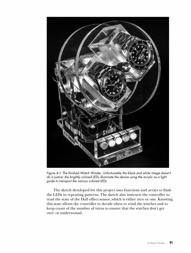
Figure 4-1: The finished Watch Winder. Unfortunately the black and white image doesn’t do it justice: the brightly colored LEDs illuminate the device using the acrylic as a light guide to transport the various colored LEDs.
The sketch developed for this project uses functions and arrays to flash the LEDs in repeating patterns. The sketch also instructs the controller to read the state of the Hall effect sensor, which is either zero or one. Knowing this state allows the controller to decide when to wind the watches and to keep count of the number of turns to ensure that the watches don’t get over- or underwound.
92 Chapter 4
t hE M Ys t IqUE Of t hE AU tOM At IC wAtCh
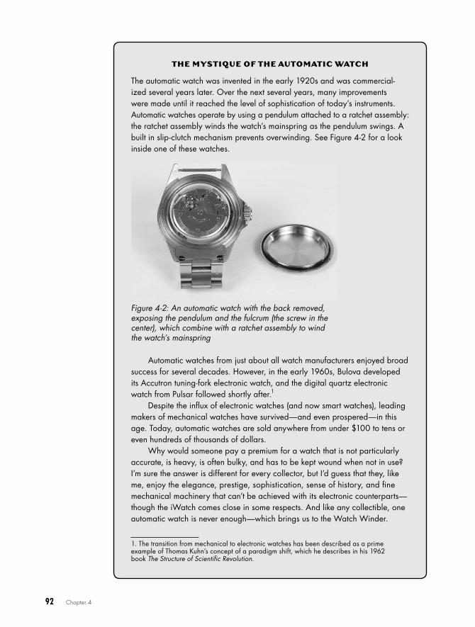
The automatic watch was invented in the early 1920s and was commercial-ized several years later . Over the next several years, many improvements were made until it reached the level of sophistication of today’s instruments . Automatic watches operate by using a pendulum attached to a ratchet assembly: the ratchet assembly winds the watch’s mainspring as the pendulum swings . A built in slip-clutch mechanism prevents overwinding . See Figure 4-2 for a look inside one of these watches .
Figure 4-2: An automatic watch with the back removed, exposing the pendulum and the fulcrum (the screw in the center), which combine with a ratchet assembly to wind the watch’s mainspring
Automatic watches from just about all watch manufacturers enjoyed broad success for several decades . However, in the early 1960s, Bulova developed its Accutron tuning-fork electronic watch, and the digital quartz electronic watch from Pulsar followed shortly after .1
Despite the influx of electronic watches (and now smart watches), leading makers of mechanical watches have survived—and even prospered—in this age . Today, automatic watches are sold anywhere from under $100 to tens or even hundreds of thousands of dollars .
Why would someone pay a premium for a watch that is not particularly accurate, is heavy, is often bulky, and has to be kept wound when not in use? I’m sure the answer is different for every collector, but I’d guess that they, like me, enjoy the elegance, prestige, sophistication, sense of history, and fine mechanical machinery that can’t be achieved with its electronic counterparts—though the iWatch comes close in some respects . And like any collectible, one automatic watch is never enough—which brings us to the Watch Winder .
1 . The transition from mechanical to electronic watches has been described as a prime example of Thomas Kuhn’s concept of a paradigm shift, which he describes in his 1962 book The Structure of Scientific Revolution .
A Watch Winder 93
required ToolsDrill and drill bits
Tapered reamer set
Small vise-grip pliers
Center punch
Weld-On 4 and Weld-On 16 acrylic bonding fluid
Assorted sandpaper, including grades from 220 to 600 and grade 1500 for final polish
Jewelers rouge or other liquid plastic polish
(Optional) Circular saw
(Optional) Thread-locking fluid
(Optional) Wire-wrap tool
(Optional) Rotary tool (For example, you could get a Dremel tool with an abrasive cutoff wheel.)
parts listIf you want to build a Watch Winder like the one pictured, you will need several pieces of acrylic and some other hardware, which I detail in this section.
Acrylic The following acrylic parts can easily be cut from a standard sheet of acrylic. Without the disks, which I recommend you purchase separately, everything can be cut from two 12×12-inch acrylic sheets (one 3/8-inch thick, one 1/4-inch thick). If you prefer, you can find vendors that will laser-cut acrylic to your dimensions. (ZLazr, among many others, is equipped to do that.) It will cost a little more than doing it yourself but will make it both cutting and finishing easier.
Four pieces with dimensions 1/4 × 2 × 1 1/2 inches (long sides of the watch basket; can be 3/8 inches)
Four pieces with dimensions 1/4 × 1 × 2 inches (short sides of the watch basket; can be 3/8 inches)
Two pieces with dimensions 3/8 × 3 × 2 inches (bearing holders of bear-ing box)
Two pieces with dimensions 3/8 × 2 × 1 1/2 inches (mounting side of bearing box)
One piece with dimensions 1/4 × 1 × 2 inches (motor mount)
Two round pieces, 3/8 inches thick and 5 inches in diameter (watch basket ends)
94 Chapter 4
Two pieces with dimensions 1 1/2 × 5 × 1/4 inches (side supports for stand)
One piece with dimensions 3/8 × 3 × 5 1/2 inches (base for stand)
One piece with dimensions 3 × 1 1/2 × 3/8 inches (lightbar)
One piece with dimensions 2 1/2 × 2 1/2 × 3/8 inches (shield mounting)
Two 3.5 mm standoffs with M/F M3-05 threads (motor mounts)
Three 1.5 mm standoffs with M/F M3-05 threads (shield mount)
There are several online vendors you could purchase the acrylic for this project from; just search for acrylic sheet on Google to find one near you. In the United States, http://www.zlazr.com/ seems to be good. At the time of this writing, I talked with the owner personally, and he said he can handle the kind of cutting required for this project with no problem.
Other Hardware and Circuit ComponentsOne Arduino Nano or clone
One Hall effect switch, such as Melexis US5881LUA (Dimensions for side supports should be 1 1/2 × 5 × 1/4. See “Building the Stand” on page 115.)
One driveshaft, 8 inches long and 1/4 inches in diameter with 28 threads per inch (I suggest brass because it’s easy to work.)
Two ball bearings (R4A-2RS)
Six jam nuts, 1/4-inch-28
Two decorative bolts, 1/4-inch-28, 1 inch long (I used chromed Allen bolts.)
Ten ZTX649 transistors
One SN754410 quad H-bridge
Ten 470-ohm resistors
One 10-kilohm, 1/8 W resistor
One 0.1 µF ceramic capacitor (C1)
One 10 µF tantalum capacitor (C2)
One custom shield as described in “The Shield” on page 108, or perf board (You can also have the shield custom fabricated from ExpressPCB; see “Making Your Own PCBs” on page 13.)
One gear head motor (I used a 6V, 20 RPM motor called the Amico 20 RPM 6VDC 0.45 A.)
One LM7805 voltage regulator
Fourteen LEDs, in assorted colors (I purchased both clear and frosted versions. The higher-output units tended to be clear.)
Assorted hookup wire and wire-wrap wire
A Watch Winder 95
Ten stakes for LED wire wrap or soldering (Try Pololu item #966 or Electronic Goldmine item #G19870.)
One length brass round that’s 3/8 or 1/2 inches in diameter and approximately 3/4 inches long (I used one with a 3/8-inch diameter. Brass stock is readily available in 6- and 12-inch lengths, which can be cut to size with a hacksaw.)
One 6-inch length of piano wire that’s 0.39 inches in diameter
One niobium, or neodymium, magnet, approximately 3/8 inches round and 1/8 inches thick
One flat-head 4-40 screw
Six M3×3/8-inch screws
Seven M3-05×1/2-inch screws
(Optional) One Amico H7EC-BCM counter
(Optional) Eight 270-ohm resistors (Use these when you build the breadboard prototype if you choose to follow my exact instructions in “The Breadboard” on page 98.)
downloadsBefore you start building, go to https://www.nostarch.com/arduinoplayground/, download the resource files for this book, and look for the following files for Chapter 4:
Templates MotorMountAndBearingBox.pdf, BaseAndLightbar.pdf, WatchBasket.pdf
Mechanical drawing MotorAssembly.pdf
Shield WatchWinder.pcb
Sketch WatchWinder.ino
Basic watch winder requirementsSome initial research suggested that a watch winder should rotate a watch between 600 and 1,200 revolutions per day to keep it in top shape. But that is not completely correct. I subsequently discovered that the range was actu-ally much wider, and according to at least two websites of leading automatic watches, watches cannot be overwound because they have a built-in protec-tion system. I also learned that watches should be rotated both clockwise and counterclockwise to keep lubricant in the right places and to avoid possible uneven wear over a very long period of time. There is a wealth of information about this subject on the web, both on sites for individual watch manufacturers as well as on sites for watch winders.

96 Chapter 4
Apparently the total number of turns is the important part, not neces-sarily the sequencing of the turns or getting exactly the same number of turns in each direction. (There is a possible downside to winding, if a watch is wound too much over an extended period.) That doesn’t sound so daunt-ing, right? I thought so, too.
using an arduino to Control winder revolutionsA purely utilitarian watch winder just has to serve its function, rotating the watches so the pendulums swing. But it’s more interesting to have a winder with extra features. As mentioned in “Why a Watch Winder?” on page 90, some winders are dressed up with fancy exotic wood boxes to display the watches.
However, this is an Arduino project, and extra technical features and LEDs should reflect the flexibility and versatility of the platform. In a devel-opmental model, the original sketch instructed the electronics to turn a motor first in one direction and then the other, using delays to ensure that the requisite 600 to 1,200 revolutions occurred each day.
But it turns out that some watches need more than the minimum number of revolutions, and some can get away with less. The easiest way to change the number of revolutions is by adjusting the various delays in the sketch as needed. You could even add hardware to the circuit to allow you to adjust the number of turns per day with a potentiometer, as I describe in “Design Notes” on page 124.
To drive the motor itself, I used an H-bridge IC. It accepts control logic from the Arduino and lets you reverse the polarity to the motor from a single power supply to allow the motor to rotate in both directions.
N O t E For more information on H-bridges, see “Using an H-Bridge” on page 48.
using a hall effect Sensor to monitor rotationsThen, there was the matter of how to meter the number of turns the device made to assist the timing and give some more information to the sketch. The number of turns per unit time is a function of the motor, and while the timing I provided for the motor specified could conceivably work, it might not be consistent for all motors.
For example, I sampled three motors of the same model at the same voltage, and each ran at a slightly different speed. Further, if you elect to substitute another motor with a different rotational speed, the rotation count would be different. And, in beta testing, one user experienced dif-ficulty running a 6V motor on 5V. (See “Motor Voltage” on page 126.) Because the number of turns per unit time is a function of the motor, these inconsistencies could present a problem if timing alone determined the total number of rotations; some mechanism to monitor the number of revolutions is needed.

A Watch Winder 97
To assure consistent timing, I decided to meter the number of turns the device made. Thus, I attached a small magnet to the rotating shaft that turns the watches and mounted a Hall effect device, or a sensor that detects a magnetic field, in line with the magnet. A small reed switch could be sub-stituted for the Hall effect sensor if you wanted.
When the watch and the magnet rotate, the Hall effect switch turns on only when in close proximity to the magnet, causing the switch to turn on and off once per rotation. Each time the Hall effect switch changes state, the Arduino increments an internal counter. Combined with the sketch, this ensures the proper number of turns per day is made in all cases, regard-less of the speed of the motor. Unlike the reed switch, the Hall effect switch does not require any buffering or debounce, as discussed in “The Sketch” on page 102, because a Schmitt Trigger is included in the device’s circuit. If you elect to use a reed switch, you may have to add the debounce into the sketch.
When using a Hall effect switch with a permanent magnet, you just have to be careful how you move the magnet around. Some mechanical watches are damaged by close proximity to a strong magnetic field because the hairspring becomes magnetized, resulting in a change in physical char-acteristics that cause timing to be off. While the magnet specified is small and unlikely to cause a problem, I strongly recommend you keep any mag-net at least an inch away from any watch—mechanical or electronic.
The SchematicFigure 4-3 shows the schematic diagram of the circuit used for the Watch Winder. Notice that the output from the Hall effect device has a pull-up resistor tied to the positive supply. This holds the input to Arduino pin A0 high until the Hall effect switch, or reed switch, encounters a strong enough magnetic field, which closes the switch and brings the pin low. The Hall effect device uses what is essentially an open collector on its output, so with-out the pull-up resistor, the collector would be left floating and could give a false trigger.
The two capacitors prevent the LM7805 regulator from oscillating on its own and drawing excessive power. Although I looked at both the input and the output of the regulator with an oscilloscope and saw no oscillation, I decided to add the capacitors as a preventative measure. I selected them based on previous projects, and they work well.
I was trying to develop a spectacular look for the Watch Winder, as befits some of the timepieces it holds, so I used higher-power LEDs, as described in the “Parts List” on page 93. These LEDs have a light output of as much as 100,000 to 200,000 or more millicandela (MCD). But that raised yet another problem. The Arduino Nano’s processor chip, an ATmega328, can source or sink only 40 mA per output pin. Further, the entire chip is rated at only 200 to 300 mA for its entire current drain. Because the 100,000+ MCD LEDs draw around 30 to 60 mA each, something had to be done.

98 Chapter 4
Figure 4-3: The Watch Winder circuit. The transistors connect to the digital outputs of the Nano, while A0 is tied high through the 10-kilohm resistor.
One 1 A transistor per LED is included in the schematic to pick up the load. The collectors of the NPN transistors—the positive side—go to VIN rather than the 5V that powers the Nano and H-bridge, so the LEDs take no toll on the voltage regulator, even though the emitters follow the base and send 5V to the LEDs.
The BreadboardJust like other projects we’ve discussed, the Watch Winder started out as a breadboard, shown in Figure 4-4. This allowed me to sound out the tech-nology and do the preliminary tuning of the sketch.
A Watch Winder 99
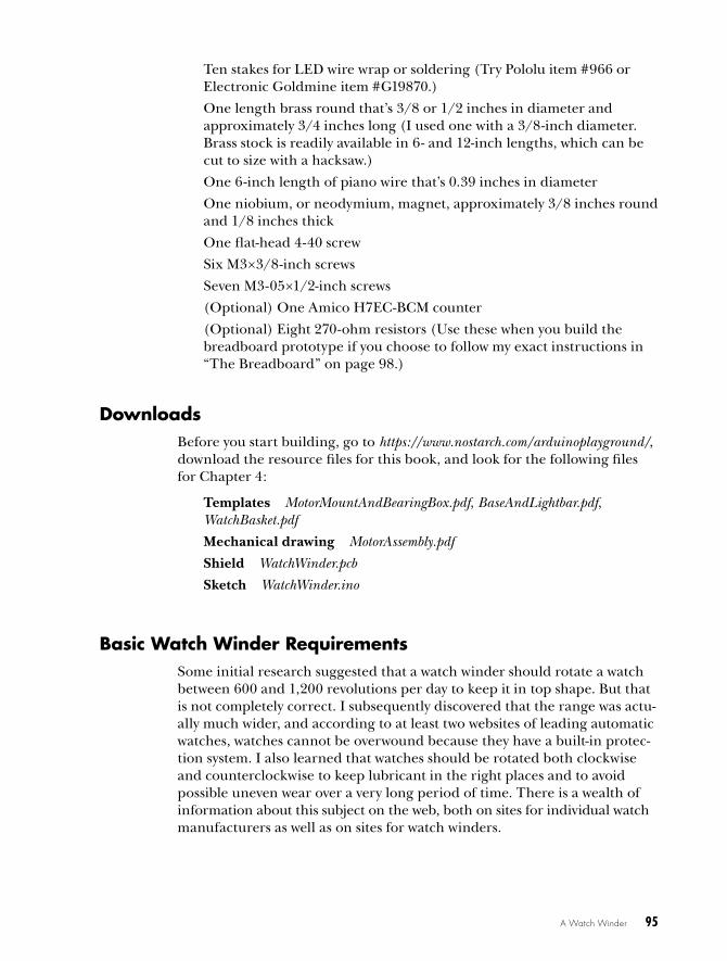
Figure 4-4: The Watch Winder breadboard was used as a proof-of-concept for the proj-ect. Here, I powered it with the Regulated Power Supply from Chapter 3.
I suggest building a breadboard for this project first so you can see where everything goes and why. With a breadboard, you also get to play with the sketch and LEDs without having to unsolder and resolder with each change. I used a 6.5-inch long breadboard to hold everything. I did take a couple of shortcuts on the breadboard, which are noted in the instructions; you can also just build straight from the schematic, instead.
To wire up the breadboard, take the following steps:
1. Connect the red stripe on the right side of the breadboard to the corre-sponding red stripe on the left. These are your positive rails.
2. Connect the blue stripe on the right side of the breadboard to the corresponding blue stripe on the left. These are your negative rails (ground connections).
3. Insert the Arduino Nano at one end.
4. Connect the 5V pin of the Nano to the red positive rail.
5. Connect the GND pin of the Nano to the blue negative rail.
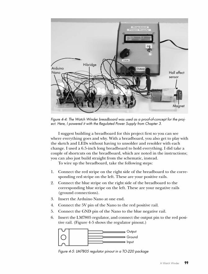
6. Insert the LM7805 regulator, and connect the output pin to the red posi-tive rail. (Figure 4-5 shows the regulator pinout.)
Output
GroundInput
Figure 4-5: LM7805 regulator pinout in a TO-220 package
Hall effect sensor
Magnet
Arduino Nano
H-bridge

100 Chapter 4
7. Connect the ground terminal of the regulator to the blue negative rail.
8. The input terminal of the regulator will connect to a blank row in the breadboard, which will connect to the +7.5V to 9V supply.
9. Connect capacitor C1 from the input of the regulator to ground.
10. Connect capacitor C2 from the output of the regulator to ground.
11. Insert the SN754410 H-bridge several rows away from the Nano, strad-dling the gutter in the middle of the breadboard. (Figure 4-6 shows the H-bridge pinout.)
16
15
14
13
12
11
10
9
1
2
3
4
5
6
7
8
Heat sink and ground
Heat sink and ground
VCC1
4A
4Y
3Y
3A
3,4ENVCC2
2A
2Y
1Y
1A
1,2EN
Figure 4-6: SN754410 H-bridge pinout in a DIP form factor
12. Connect pins 4, 5, 12, and 13 of the H-bridge to ground.
13. Connect pins 8, 9, and 16 of the H-bridge to the red positive rail.
14. Attach pins 14 and 11 of the H-bridge to the motor with leads at least 10 to 12 inches long. The connections to the motor will have to be soldered unless you use alligator clips or clip leads.
15. Attach approximately 8-inch wires to all three leads of the Hall effect sensor. Connect the leads attached to the positive and negative leads of the Hall effect sensor to the red positive rail and blue negative rail, respectively.
16. Connect the wire attached to the third pin of the Hall effect sensor to pin A0 on the Nano. The Hall effect sensor will be taped (I used mask-ing tape) to the motor body (this works because the leads are insulated) in such a position that the active part of the device will be close to the magnet attached to the shaft as it goes around.
17. Connect a 10-kilohm resistor from pin A0 on the Nano to the red posi-tive rail.
18. Connect pin 10 of the H-bridge to pin D13 on the Nano.
19. Connect pin 15 of the H-bridge to pin D12 on the Nano.
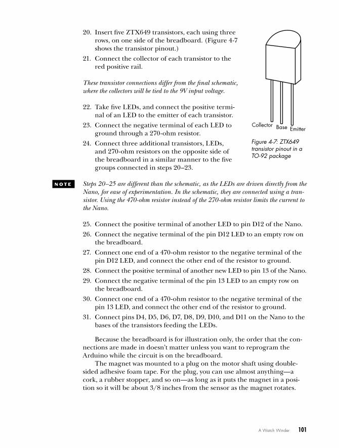
EmitterCollector Base
Figure 4-7: ZTX649 transistor pinout in a TO-92 package
A Watch Winder 101
20. Insert five ZTX649 transistors, each using three rows, on one side of the breadboard. (Figure 4-7 shows the transistor pinout.)
21. Connect the collector of each transistor to the red positive rail.
N O t E These transistor connections differ from the final schematic, where the collectors will be tied to the 9V input voltage.
22. Take five LEDs, and connect the positive termi-nal of an LED to the emitter of each transistor.
23. Connect the negative terminal of each LED to ground through a 270-ohm resistor.
24. Connect three additional transistors, LEDs, and 270-ohm resistors on the opposite side of the breadboard in a similar manner to the five groups connected in steps 20–23.
N O t E Steps 20–25 are different than the schematic, as the LEDs are driven directly from the Nano, for ease of experimentation. In the schematic, they are connected using a tran-sistor. Using the 470-ohm resistor instead of the 270-ohm resistor limits the current to the Nano.
25. Connect the positive terminal of another LED to pin D12 of the Nano.
26. Connect the negative terminal of the pin D12 LED to an empty row on the breadboard.
27. Connect one end of a 470-ohm resistor to the negative terminal of the pin D12 LED, and connect the other end of the resistor to ground.
28. Connect the positive terminal of another new LED to pin 13 of the Nano.
29. Connect the negative terminal of the pin 13 LED to an empty row on the breadboard.
30. Connect one end of a 470-ohm resistor to the negative terminal of the pin 13 LED, and connect the other end of the resistor to ground.
31. Connect pins D4, D5, D6, D7, D8, D9, D10, and D11 on the Nano to the bases of the transistors feeding the LEDs.
Because the breadboard is for illustration only, the order that the con-nections are made in doesn’t matter unless you want to reprogram the Arduino while the circuit is on the breadboard.
The magnet was mounted to a plug on the motor shaft using double-sided adhesive foam tape. For the plug, you can use almost anything—a cork, a rubber stopper, and so on—as long as it puts the magnet in a posi-tion so it will be about 3/8 inches from the sensor as the magnet rotates.
7. Connect the ground terminal of the regulator to the blue negative rail.
8. The input terminal of the regulator will connect to a blank row in the breadboard, which will connect to the +7.5V to 9V supply.
9. Connect capacitor C1 from the input of the regulator to ground.
10. Connect capacitor C2 from the output of the regulator to ground.
11. Insert the SN754410 H-bridge several rows away from the Nano, strad-dling the gutter in the middle of the breadboard. (Figure 4-6 shows the H-bridge pinout.)
16
15
14
13
12
11
10
9
1
2
3
4
5
6
7
8
Heat sink and ground
Heat sink and ground
VCC1
4A
4Y
3Y
3A
3,4ENVCC2
2A
2Y
1Y
1A
1,2EN
Figure 4-6: SN754410 H-bridge pinout in a DIP form factor
12. Connect pins 4, 5, 12, and 13 of the H-bridge to ground.
13. Connect pins 8, 9, and 16 of the H-bridge to the red positive rail.
14. Attach pins 14 and 11 of the H-bridge to the motor with leads at least 10 to 12 inches long. The connections to the motor will have to be soldered unless you use alligator clips or clip leads.
15. Attach approximately 8-inch wires to all three leads of the Hall effect sensor. Connect the leads attached to the positive and negative leads of the Hall effect sensor to the red positive rail and blue negative rail, respectively.
16. Connect the wire attached to the third pin of the Hall effect sensor to pin A0 on the Nano. The Hall effect sensor will be taped (I used mask-ing tape) to the motor body (this works because the leads are insulated) in such a position that the active part of the device will be close to the magnet attached to the shaft as it goes around.
17. Connect a 10-kilohm resistor from pin A0 on the Nano to the red posi-tive rail.
18. Connect pin 10 of the H-bridge to pin D13 on the Nano.
19. Connect pin 15 of the H-bridge to pin D12 on the Nano.
EmitterCollector Base
Figure 4-7: ZTX649 transistor pinout in a TO-92 package
102 Chapter 4
After you complete the breadboard, upload the WatchWinder.ino sketch to the Arduino. Just follow the instructions in “Uploading Sketches to Your Arduino” on page 5.
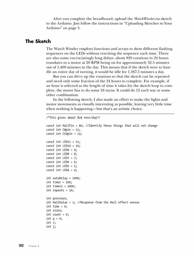
The SketchThe Watch Winder employs functions and arrays to show different flashing sequences on the LEDs without rewriting the sequence each time. There are also some excruciatingly long delays: about 829 rotations in 24 hours translates to a motor at 20 RPM being on for approximately 32.5 minutes out of 1,400 minutes in the day. This means that if the sketch were to han-dle an entire day of turning, it would be idle for 1,367.5 minutes a day.
But you can divvy up the rotations so that the sketch can be repeated and need only some fraction of the 24 hours to complete. For example, if an hour is selected as the length of time it takes for the sketch loop to com-plete, the motor has to do some 24 turns. It could do 12 each way or some other combination.
In the following sketch, I also made an effort to make the lights and motor movements as visually interesting as possible, leaving very little time when nothing is happening—but that’s an artistic choice.
/*This gives about 829 revs/day*/ const int HallPin = A0; //Identify those things that will not changeconst int CWpin = 12;const int CCWpin = 13;
const int LED11 = 11;const int LED10 = 10;const int LED9 = 9;const int LED8 = 8;const int LED7 = 7;const int LED6 = 6;const int LED5 = 5;const int LED4 = 4;
int autoDelay = 1000;int timer = 500;int timer2 = 3000;int repeats = 10;
int previous;int HallValue = 1; //Response from the Hall effect sensorint time = 0;int state;int count = 0;int q = 0;int i;int j;

A Watch Winder 103
int ledPins[] = { 11, 4, 7, 6, 8, 10, 5, 9,};int pinCount = 8;
void blinkIt() { //Initiate rapid blink sequence for(int thisPin = 0; thisPin < pinCount; thisPin++) { //Turn the pin on: digitalWrite(ledPins[thisPin], HIGH); delay(timer2); //Turn the pin off: digitalWrite(ledPins[thisPin], LOW); delay(timer2); }
//Loop from the highest pin to the lowest: for(int thisPin = pinCount - 1; thisPin >= 0; thisPin--) { //Turn the pin on: digitalWrite(ledPins[thisPin], HIGH); delay(timer2); //Turn the pin off: digitalWrite(ledPins[thisPin], LOW); delay(timer2); }}
void flashIt() { //Initiate rapid blink sequence for(int thisPin = 0; thisPin < pinCount; thisPin++) { //Turn the pin on: digitalWrite(ledPins[thisPin], HIGH); delay(timer2); //Turn the pin off: digitalWrite(ledPins[thisPin], LOW); }
//Loop from the highest pin to the lowest: for(int thisPin = pinCount - 1; thisPin >= 0; thisPin--) { //Turn the pin on: digitalWrite(ledPins[thisPin], HIGH); delay(timer2); //Turn the pin off: digitalWrite(ledPins[thisPin], LOW); }}
void allatOncefast() { { digitalWrite(LED4, HIGH); digitalWrite(LED5, HIGH); digitalWrite(LED6, HIGH); digitalWrite(LED7, HIGH); digitalWrite(LED8, HIGH); digitalWrite(LED9, HIGH);

104 Chapter 4
digitalWrite(LED10, HIGH); digitalWrite(LED11, HIGH);
delay(500);
digitalWrite(LED4, LOW); digitalWrite(LED5, LOW); digitalWrite(LED6, LOW); digitalWrite(LED7, LOW); digitalWrite(LED8, LOW); digitalWrite(LED9, LOW); digitalWrite(LED10, LOW); digitalWrite(LED11, LOW);
delay(500); }}
void allatOnce() { { digitalWrite(LED4, HIGH); digitalWrite(LED5, HIGH); digitalWrite(LED6, HIGH); digitalWrite(LED7, HIGH); digitalWrite(LED8, HIGH); digitalWrite(LED9, HIGH); digitalWrite(LED10, HIGH); digitalWrite(LED11, HIGH);
delay(4000);
digitalWrite(LED4, LOW); digitalWrite(LED5, LOW); digitalWrite(LED6, LOW); digitalWrite(LED7, LOW); digitalWrite(LED8, LOW); digitalWrite(LED9, LOW); digitalWrite(LED10, LOW); digitalWrite(LED11, LOW);
delay(2000); }}
void setup() { pinMode(HallPin, INPUT); //Identifies inputs and outputs pinMode(CWpin, OUTPUT); pinMode(CCWpin, OUTPUT);
Serial.begin(9600);
for(int thisPin = 0; thisPin < pinCount; thisPin++) { pinMode(ledPins [thisPin], OUTPUT); }}

A Watch Winder 105
void loop() { int HallValue = (digitalRead(HallPin)); //Sets value of initial Hall effect
if(HallValue == HIGH && previous == LOW) { if(state == HIGH) state = LOW; else state = HIGH;
//Increments counter each time the Hall effect sensor passes the magnetu count++;
}
/* The "Serial.print" line was used in development. I left it in so that you can experiment and look at some of the values on a serial monitor. You might even want to change the parameters of what you are looking at in the monitor. */ Serial.print("HallValue "); Serial.println(HallValue); Serial.print("count "); Serial.println(count); Serial.print("CCW "); Serial.println(" ");
if(count == 1) { digitalWrite(CCWpin, HIGH); digitalWrite(CWpin, LOW); }
if(count == 3) { digitalWrite(CWpin, HIGH); digitalWrite(CCWpin, HIGH); }
if(count == 3) { for(i = 0; i < repeats; i++) { allatOncefast(); } count = count + 1; }
if(count == 3) { digitalWrite(CWpin, LOW); digitalWrite(CCWpin, HIGH); }
if(count == 4) { digitalWrite(CWpin, HIGH); digitalWrite(CCWpin, HIGH); }

106 Chapter 4
if(count == 4) { for(q = 0; q < repeats; q++) { blinkIt(); } count = count + 1; }
if(count == 5) { for(j = 0; j < repeats; j++) { allatOnce(); } delay(50); count = count + 1; }
if(count == 6) { digitalWrite(CCWpin, LOW); digitalWrite(CWpin, HIGH); }
if(count == 7) { digitalWrite(CWpin, LOW); digitalWrite(CCWpin, LOW); }
if(count == 7) { for(i = 0; i < repeats; i++) { flashIt(); } count = count + 1; }
if(count == 8) { digitalWrite(CCWpin, HIGH); digitalWrite(CWpin, LOW); }
if(count == 10) { for(i = 0; i < repeats; i++) { allatOncefast(); } count = count + 1; }
if(count == 11) { digitalWrite(CCWpin, LOW); digitalWrite(CWpin, LOW); }
if(count == 11) { for(i = 0; i < repeats; i++) { blinkIt(); }

A Watch Winder 107
delay(2000); count = count + 1; }
if(count == 12) { digitalWrite(CCWpin, LOW); digitalWrite(CWpin, HIGH); }
if(count == 13) { digitalWrite(CCWpin, HIGH); digitalWrite(CWpin, HIGH); }
if(count == 13) { for(i = 0; i < repeats; i++) { flashIt(); } count = count + 1; }
if(count == 14) { for(i = 0; i < repeats; i++) { allatOnce(); } }
if(count == 14) { digitalWrite(CWpin, LOW); digitalWrite(CCWpin, HIGH); delay(autoDelay); }
if(count == 17) { digitalWrite(CWpin, HIGH); digitalWrite(CCWpin, HIGH); }
if(count == 17) { for(i = 0; i < 20; i++) { blinkIt(); } }
{ for(i = 0; i < repeats; i++) { allatOncefast(); } count = count + 1; }

108 Chapter 4
if(count == 18) { digitalWrite(CCWpin, HIGH); digitalWrite(CWpin, LOW); delay(2000); digitalWrite(CCWpin, LOW); digitalWrite(CWpin, HIGH); delay(2000); }
if(count > 20) {v count = 0;
} previous = HallValue;}
First, the sketch creates several constants, integers, and arrays, which assist with timing turns by reading from the Hall effect sensor and counting the turns. Next, come a few function definitions: blinkIt() and flashIt() blink the LEDs in different patterns, while allatOnceFast() and allatOnce() blink the LEDs all at the same time with different delays.
As usual, the setup() function tells the Arduino which pins are inputs and outputs. At the start of the loop() function, the Hall effect sensor is read, and the sketch increments the counter at u as needed, printing a few useful debugging values to the serial monitor along the way. This sketch uses the count value to turn different sequences on or off and limit the rep-etitions. However, because count is reset at the end of the sequence at v, it cannot be used as a totalizer.
Finally, for various counts, the sketch uses if statements to hard-code different patterns for turning the watches and flashing the LEDs; I show a few here, but I encourage you to set up your own. The sketch is written with many functions you can use as-is or repeat in a for loop to give multiple iterations.
The ShieldAs in some of the other Arduino projects, the shield is not terribly complex, but it looks a little busy. For simplicity, this shield is a single-sided board. The circuit uses an LM7805 voltage regulator to handle excess current that could result from using a different motor. The on-board regulator built into the Nano is intended only for currents less than 300 mA.
N O t E I have used the regulator in this project at up to 500 mA, but the regulator tends to get pretty warm, and I don’t feel comfortable using it at that level.
You may be able to leave the regulator out; the collectors of the transis-tors feeding the high-output LEDs are configured as emitter-followers and wired directly to the positive 9V supply, so they are not contributing to the load on the regulated 5V.

A Watch Winder 109
Figure 4-8 shows the foil pattern for the shield (left), and the silk-screen layer (right).
Figure 4-8: The foil pattern of the shield (left) and the silk-screen layer (right). The Watch Winder shield’s silk-screen layer shows the approximate placement of the Nano, H-bridge, contacts for the external counter, Hall effect sensor, potentiometer, LED connections, jumpers, input voltage (VIN), and ground (GND). The PCB Express file is available to download from https://www .nostarch .com/arduinoplayground/.
Notice the contacts for the Hall effect switch at the top of the board, labeled Hall. I soldered wires that connected the Hall effect device directly to the PCB, though you could use a connector if you prefer.
In the center of the board, I left connections for a potentiometer (POT) for external adjustment of the period, an option I describe in “Total Rotation Adjustment” on page 124. The numbers of the digital outputs are labeled at the left-hand side.
If you choose to assemble the Watch Winder shield, note that the Nano is meant to be plugged into female headers soldered onto the shield and that the transistors are underneath the Nano board. Push the transistors down far enough before you solder them so they will not be in the way of the Nano when it’s plugged in. I had to place the transistors fairly close to fit all the connections into the PCB layout. The ZTX649 transistors I selected fit well enough within the 0.100-inch spacing allowed by the foot-print of the Nano.
You will also have to add a few jumper wires to complete the con-nections on the shield. They are marked on the silk-screen pattern. In Figure 4-8, those appear as five black lines. Don’t forget to include them when wiring up the board. I also left out the capacitors from the LM7805 regulator’s input and output to ground; in the finished board, they are soldered on externally. If you want those capacitors, simply solder a 10.0 µF tantalum and a 0.1 µF ceramic capacitor directly to the pins of the regula-tor, as shown in the schematic in Figure 4-3.

110 Chapter 4
overview of the motor assemblyWhen you’ve had enough fun watching the LEDs blink on the breadboard, watching the motor start and stop, and playing with the sketch, it’s time to address the mechanical side of this project, which offers a few special challenges. This winder won’t be functional until the motor has something to turn; see Figure 4-9 for a detailed diagram of the motor, motor mount, transmission, bearing box, and driveshaft, which comprise the turning assembly.
Jam nut
Ball bearing
Vinyl tubing
Piano wire
Motor shaft
BushingSet screw
Piano wire
Motor
Figure 4-9: The construction entails making a small box that retains the bearings through which the driveshaft is mounted and held in place by jam nuts. The motor, mounted on standoffs, is connected to the driveshaft, and the watch basket will be attached to the other end of the driveshaft.
The driveshaft will need to be mounted through the bearings, and the two can be held together with jam nuts. I chose a fairly standard R4A-2RS bearing, which is a relatively common part and has a 3/4-inch outer diameter, a 1/4-inch inner diameter, and a 9/16-inch thickness. I suggest ball bear-ings because the prebuilt winder I bought used the brass bushing of the motor as the only bearing, and that’s what failed. Because the inside diam-eter of the bearing was 1/4 inches, I decided to use a standard threaded rod at a 1/4-inch × 20 tpi (turns per inch) or 1/4-inch × 28 tpi rather than attempt to press-fit a 1/4-inch bar into the bearing.
N O t E I used jam nuts to fasten the rod to the bearings because they were thinner and less obtrusive looking than regular nuts, but you could also use standard nuts.
Construction Construction of the winder provided a number of challenges, particularly working with the acrylic material—which was unfamiliar to me before this project. Though there were some rough spots to get over, I learned by trial and error some ways to get the job done. Figure 4-10 shows the completed Watch Winder on its side.

A Watch Winder 111
Figure 4-10: The completed Watch Winder on its side, showing the base fabrication, bearing box, motor mount, and watch basket
The toughest part was cutting the acrylic and drilling the holes for the ball bearings. There are several ways to cut acrylic, and none of them is particularly easy. If you use a supplier that will laser-cut the acrylic parts for you, this will be a lot easier. Several companies offer that service for a little more than the price of the raw materials. I mentioned one of them, ZLazr, earlier.
If you have access to a circular saw, that’s about one of the easiest DIY approaches. Otherwise, just about any saw will do. I’ve used a hacksaw, which works better than most if you take your time. (If you go too fast, the acrylic will heat up and start to melt, causing the saw to bind.) I even know some people who have had success scoring and snapping the acrylic sheet. Just use whichever approach works best for you.
See “Acrylic” on page 93 for a list of acrylic shapes needed for the bear-ing box, the watch basket, and the stand. Cut these pieces now, if you’ve not done so already, and take the following steps to build the pieces.
Preparing the Motor Mount and Bearing Box AcrylicFirst, print the motor mount template from this chapter’s folder (see Figure 4-11), cut it out, and align it on the acrylic for the motor mount using the centerline.

112 Chapter 4
D EF
A BC
0.33 in
0.69 in
Motor mount
Bearing box
Figure 4-11: Templates for motor mount and bearing box. You can download the templates at https://www .nostarch .com/arduinoplayground/.
Tape the template to the acrylic, lining up the centerline on the center of the acrylic piece, and mark the drill centers for holes A, B, D, E, and F. To mark the holes, just punch the centers with a center punch or nail. Now, drill them; use a 1/8-inch bit for A, B, D, and E and a 3/8-inch bit for F.
Then, set this piece aside, and gather the acrylic for the bearing box. The final bearing box will look like Figure 4-12 once we put it all together.
Figure 4-12: Completed bearing box, before final trim and polish. One bearing is temporarily in place.
Use the bearing box template to mark the drill centers for holes A, B, and C on one of the bearing mount pieces. C will be the bearing hole, and A and B will be for the motor mount’s standoffs. Center punch and drill one of the bearing plate’s two smaller holes with a 2.5 mm (or #39) drill and tap the hole with a M3-05 tap. These holes will accept the standoffs for mounting the motor. Use the same template to mark only the bearing hole
A Watch Winder 113
(C) on the acrylic for the opposite side of the bearing box. Then, take the two pieces of bearing box acrylic that won’t hold bearings, and mark the center by drawing lines from corner to corner. Center punch them, and drill 1/4-inch holes for mounting to the stand.
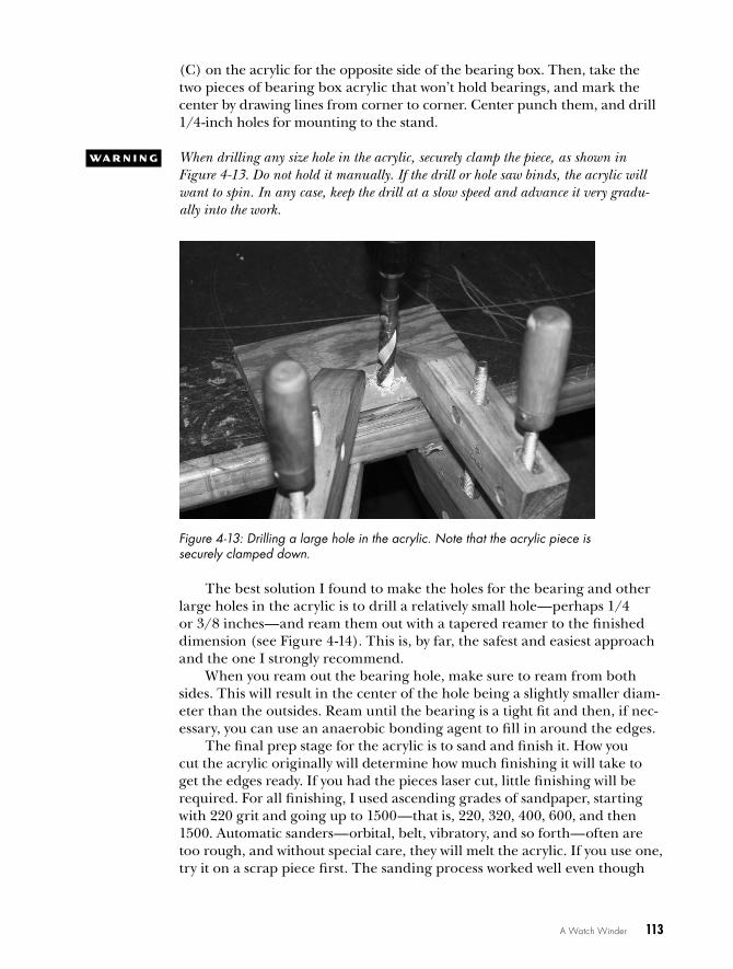
w A R N I N G When drilling any size hole in the acrylic, securely clamp the piece, as shown in Figure 4-13. Do not hold it manually. If the drill or hole saw binds, the acrylic will want to spin. In any case, keep the drill at a slow speed and advance it very gradu-ally into the work.
Figure 4-13: Drilling a large hole in the acrylic. Note that the acrylic piece is securely clamped down.
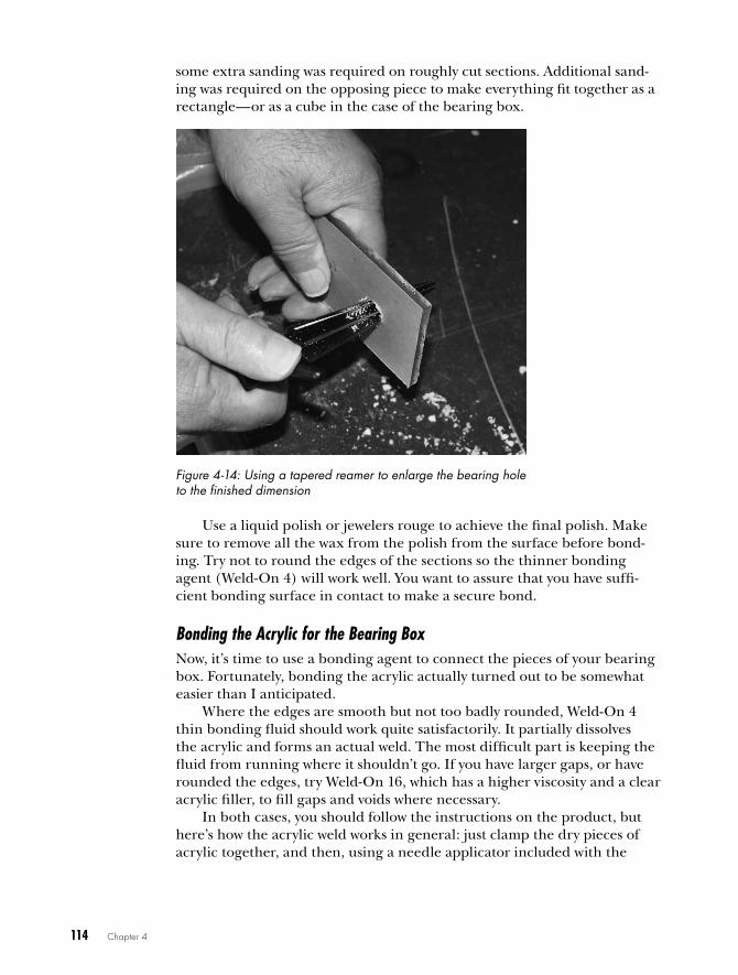
The best solution I found to make the holes for the bearing and other large holes in the acrylic is to drill a relatively small hole—perhaps 1/4 or 3/8 inches—and ream them out with a tapered reamer to the finished dimension (see Figure 4-14). This is, by far, the safest and easiest approach and the one I strongly recommend.
When you ream out the bearing hole, make sure to ream from both sides. This will result in the center of the hole being a slightly smaller diam-eter than the outsides. Ream until the bearing is a tight fit and then, if nec-essary, you can use an anaerobic bonding agent to fill in around the edges.
The final prep stage for the acrylic is to sand and finish it. How you cut the acrylic originally will determine how much finishing it will take to get the edges ready. If you had the pieces laser cut, little finishing will be required. For all finishing, I used ascending grades of sandpaper, starting with 220 grit and going up to 1500—that is, 220, 320, 400, 600, and then 1500. Automatic sanders—orbital, belt, vibratory, and so forth—often are too rough, and without special care, they will melt the acrylic. If you use one, try it on a scrap piece first. The sanding process worked well even though
114 Chapter 4
some extra sanding was required on roughly cut sections. Additional sand-ing was required on the opposing piece to make everything fit together as a rectangle—or as a cube in the case of the bearing box.
Figure 4-14: Using a tapered reamer to enlarge the bearing hole to the finished dimension
Use a liquid polish or jewelers rouge to achieve the final polish. Make sure to remove all the wax from the polish from the surface before bond-ing. Try not to round the edges of the sections so the thinner bonding agent (Weld-On 4) will work well. You want to assure that you have suffi-cient bonding surface in contact to make a secure bond.
Bonding the Acrylic for the Bearing BoxNow, it’s time to use a bonding agent to connect the pieces of your bearing box. Fortunately, bonding the acrylic actually turned out to be somewhat easier than I anticipated.
Where the edges are smooth but not too badly rounded, Weld-On 4 thin bonding fluid should work quite satisfactorily. It partially dissolves the acrylic and forms an actual weld. The most difficult part is keeping the fluid from running where it shouldn’t go. If you have larger gaps, or have rounded the edges, try Weld-On 16, which has a higher viscosity and a clear acrylic filler, to fill gaps and voids where necessary.
In both cases, you should follow the instructions on the product, but here’s how the acrylic weld works in general: just clamp the dry pieces of acrylic together, and then, using a needle applicator included with the
A Watch Winder 115
bonding agent, apply a thin layer of acrylic cement to each joint. Capillary action will draw the cement into the joint. For joints where the surfaces are a little more uneven, you can apply the thicker Weld-On 16 to one surface and then attach it to the other surface. Clamping is required for only a few minutes, but allow several hours for final curing.
The system doesn’t need a lot of strength, but it should not fall apart when touched. For the parsimonious, a paint stripper like Klean Strip also works well to bond the acrylic. (The chemical behind the bonding agent in Weld-On is methyl chloride, which is the key ingredient in the paint strip-per.) Klean Strip is less than one-fourth the price of Weld-On.
N O t E There are several tutorials on bonding acrylic on the web, too. If in doubt, look one up, and experiment with a few scrap pieces of acrylic first before trying it out on the pieces you worked so hard on.
After bonding the bearing box, as shown in Figure 4-9, and bonding the side pieces to the bottom, check the alignment. Run the threaded rod through the bearings, and put the jam nuts in place without over-tightening them. Make sure the bearings don’t bind. If they are not well centered, this can happen, but usually, they will align themselves as you tighten the jam nuts a little. If your alignment is off, you may need to adjust the holes a little with the reamer and touch up with some acrylic cement, but I never ran into that problem. For now, remove the driveshaft from the bearing box.
Building the StandThe stand is the least complex part of the project. It comprises the two side supports, 1 1/2 × 5 × 1/4 inches, and the base, 3/8 × 3 × 5 1/2 inches. I included the lightbar, 3 × 1 1/4 × 3/8 inches, and the shield mounting, 2 1/2 × 2 1/2 × 3/8 inches, with the stand (see Figure 4-15).
First, drill 1/4-inch holes in each side support a 1/2 inch from the top, centered left to right. Then, bond the two side supports to the base 1 1/2 inches in from the edge of the base that will be the back. Next, drill the holes for the LEDs in the lightbar. I used five LEDs (red, blue, white, yellow, and green) that were 10 mm in size. You can use whatever color combination you choose.
Finally, drill and mount the shield. To find the center of the piece, mark from corner to corner. Then, in the center, drill a #43 hole and tap for a 4-40 screw. Drill a corresponding hole, centered and 2 inches from the rear edge, in the base. Next, use the shield itself, or the drawing from the ExpressPCB print, as a template to drill a hole for the three mounting screws. In design-ing the board, I failed to leave room for a fourth screw. However, three are more than sufficient, as there is no mechanical force on the board. I used a

116 Chapter 4
2.5 mm (#39) drill and tap for a M3-05 screw that the standoffs will fit into. Figure 4-15 shows the dimensions of the parts and the partially assembled base, including supports, the lightbar, and the shield mount.
2.5 in
1.5 in
Side supports
Base
2.5 in 5 in
5.5 in
0.375 in
0.375 in
1.25 in
Drill #43Tap 4-40
Use shield as templateto drill mounting holes
Lightbar
3 in
1.5 in
0.5 in
Figure 4-15: The components and configuration of the base and lightbar for the Watch Winder
Preparing the Motor and the DriveshaftDespite a concerted effort to mark and drill the holes accurately, you may still end up with misalignment between the motor and driveshaft, so this build aims to keep the coupling flexible. My solution might not be on the hit parade of industrial engineers, but I used a length of vinyl tubing to couple the motor to the driveshaft. This coupling has been working for more than a year with no sign of deterioration or problems.
A 1-inch length of heavy-wall vinyl tubing with an outside diameter of 7/16 inches and an inside diameter of 3/16 inches should do the job.
It won’t fit the motor shaft or the 1/4-inch threaded shaft without a bit of work, though. (I drove the sales clerk at Lowe’s batty buying six of each size they had in stock.) We simply need to reduce the diameter of the threaded shaft and craft a small bushing for the motor shaft.
Trimming the Threaded Shaft
First, trim the diameter of the threaded shaft. Clamp a hand-held electric drill in a vise or parallel clamp, using a folded towel to keep from damag-ing the drill, and place the shaft where the drill bit would normally go (see Figure 4-16). Then, turn on the drill, and use a sharp file to trim the shaft.

A Watch Winder 117
Figure 4-16: Reducing the diameter of the threaded shaft
It should take only a minute or two to reduce the shaft diameter to a little over 3/16 inches for a tight fit on the vinyl tubing.
Creating the Motor Bushing
Next, take a small piece of round stock approximately 3/4 inches long and 3/8 to 1/2 inches in diameter. (I used a 3/8-inch diameter, as it required less work.) Drill a 11/64-inch (#21) hole in the end approximately 3/8 inches deep. The bushing hole needs to be as close to the center as possible, so you might want to mark it with a center punch first (see Figure 4-17).
Figure 4-17: Clamp the shaft of the piece used as the bushing in a vise or pair of vise-grip pliers, and center punch a mark before drilling the hole. Get as close to the center as possible.
118 Chapter 4
Then, place the short piece of stock you cut in the drill as you did the threaded shaft with the center hole toward the drill. File the end without the hole in it. Reduce the diameter by about 1/4 inches to approximately equal the filed end of the driveshaft.
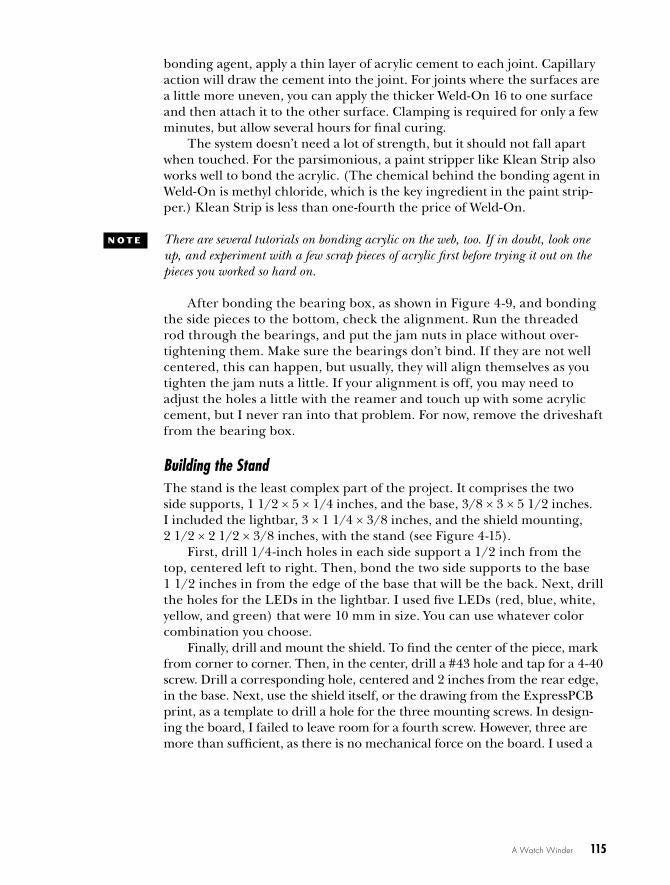
Next, drill a 0.041-inch hole through the bushing, about 3/8 inches from the edge of the bushing.
While you’re at it, drill a corresponding hole in the driveshaft. To center punch and drill the driveshaft and the bushing holes, file the end flat so the center punch can find a purchase (see Figure 4-18). These are the holes that will accept the piano wire through the vinyl tubing.
Figure 4-18: The easiest way to drill the holes in the threaded rod and bushing is to file a small flat on the shaft and center punch.
Finally, drill a 2.5 mm (#39) hole and tap an M3-05 hole in the bush-ing, perpendicular to the hole drilled for the motor shaft. This will accept a set screw for the motor shaft. If you prefer, you can drill a #43 hole and tap for a 4-40 set screw. This set screw holds the bushing in place on the motor shaft, and the two 0.041-inch holes drilled in the driveshaft and motor bushing, respectively, will pin the vinyl tubing in place with piano wire.
Cutting Piano Wire Pins and Completing the Motor Assembly
Cut two pieces of 0.039-inch wide piano wire, 1/2 to 5/8 inches long. This can be a bit of a job. I used an abrasive cutoff wheel on a Dremel tool. Using the corner of a small grinding wheel attached to the drill should work to put a groove in the wire. Once you have a groove in the wire, you can snap it by hand. You can also use any sharpening stone to score the wire, and it should easily snap.
Flat-filed
Center punch
A Watch Winder 119
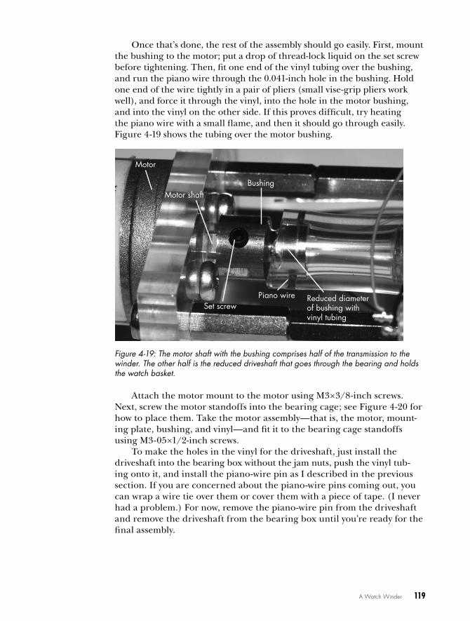
Once that’s done, the rest of the assembly should go easily. First, mount the bushing to the motor; put a drop of thread-lock liquid on the set screw before tightening. Then, fit one end of the vinyl tubing over the bushing, and run the piano wire through the 0.041-inch hole in the bushing. Hold one end of the wire tightly in a pair of pliers (small vise-grip pliers work well), and force it through the vinyl, into the hole in the motor bushing, and into the vinyl on the other side. If this proves difficult, try heating the piano wire with a small flame, and then it should go through easily. Figure 4-19 shows the tubing over the motor bushing.
Figure 4-19: The motor shaft with the bushing comprises half of the transmission to the winder. The other half is the reduced driveshaft that goes through the bearing and holds the watch basket.
Attach the motor mount to the motor using M3×3/8-inch screws. Next, screw the motor standoffs into the bearing cage; see Figure 4-20 for how to place them. Take the motor assembly—that is, the motor, mount-ing plate, bushing, and vinyl—and fit it to the bearing cage standoffs using M3-05×1/2-inch screws.
To make the holes in the vinyl for the driveshaft, just install the driveshaft into the bearing box without the jam nuts, push the vinyl tub-ing onto it, and install the piano-wire pin as I described in the previous section. If you are concerned about the piano-wire pins coming out, you can wrap a wire tie over them or cover them with a piece of tape. (I never had a problem.) For now, remove the piano-wire pin from the driveshaft and remove the driveshaft from the bearing box until you’re ready for the final assembly.
Motor shaftBushing
Set screwReduced diameter of bushing with vinyl tubing
Piano wire
Motor

120 Chapter 4
Standoffs
Figure 4-20: Motor and motor mount connected to bearing box with stand-offs. The standoffs are threaded into the bearing box while the motor mount is fastened with 3 mm × 1/2-inch screws and washers. The bearing box is mounted to stand with 1-inch-long, 1/4-inch × 28 screws and nuts.
Making the Watch BasketThere are many ways to construct the part of the project that holds the watches. I chose to make my watch basket from acrylic. The construction is relatively straightforward, though it does require some patience. First, take two 5×3/8-inch acrylic disks and carefully mark the center on each. Drill 1/4-inch holes in the center of each. Then, on what will be the top disk, mark the rectangles shown in Figure 4-21 (left).
If you’ve not done so already, cut the rectangular acrylic pieces I described in the “Parts List” on page 93 for the watch boxes and assemble them following the same instructions given under “Bonding the Acrylic for the Bearing Box” on page 114. (In most of the samples I’ve made, I used 1/4-inch acrylic; however, 3/8-inch acrylic works fine.) Then, carefully mark out the openings on the disk (see Figure 4-21). Now, bond the watch baskets to one disk, as shown in Figure 4-22. Then, cut the openings to match up with the inside of the watch baskets.

A Watch Winder 121
3 in
0.25 in
0.25 in
2 in1 in
1 in
Figure 4-21: Cut out dimensions for the watch holder basket. This pattern can be down-loaded as a PDF file from http://www .nostarch .com/arduinoplayground/.
Figure 4-22: The watch holder baskets mounted to the acrylic disk. Above them is the fully assembled motor, bearing box, and driveshaft.
The simplest way to cut the rectangles out is to drill a hole at the cor-ners, being careful not to drill into the watch basket, and use a keyhole or coping saw (or if you’re careful, a saber saw) to cut the openings. They have to be cut only on one disk, which will be the top. You can clean up the edges of the cuts a little with a file or sandpaper, but don’t spend too much time as it will not be noticeable with the watches and cushions in place.

122 Chapter 4
Finally, mount the basket on the driveshaft. First, thread two nuts onto the driveshaft and lock them against each other—that is, tighten one nut against the other. Then, add a washer, followed by the lower disk of the bas-ket, the top assembly with the watch baskets, a washer, and a nut at the top. If you desire, go to the hardware store to search for a decorative nut to cap off the project.
N O t E Bonding the bottom disk isn’t necessary if you use locking nuts as I described and tighten the basket securely. I didn’t bond the boxes to the lower disk, and it has not been a problem.
At this point, you can mount the finished assembly to the stand using the two decorative 1/4 inch × 28 bolts and nuts. You can also bond the light-bar to the base using acrylic cement and drill the hole for mounting the shield mounting plate.
Adding the LEDsYou’re just about done. Locate and mount the LEDs on the acrylic any-where you like, and wire them up to the shield. You can see where I placed mine in Figure 4-1. (The way the acrylic conducts the light produces some neat effects.) You may want to drill some blind holes to mount the LEDs in. Simply drill a hole the diameter of the LED but not completely through the acrylic. If you’re careful, you can probably do a neat job in running the wires so they can barely be seen.
Because the LEDs are critical to the ultimate appearance of the winder, their placement and mounting is an important component of the finished product. Drilling the holes for mounting the LEDs can be a little tricky because if you bought a variety, they may have slightly different diameters. As a starting point, try 3/16-inch holes for 5 mm LEDs and 25/64-inch holes for 10 mm LEDs. I found the best way to get the right size was to drill a sample hole in a scrap piece of stock and try it before venturing to drill into a finished piece. If the hole is a bit small, a simple touch up with the tapered reamer should fix that. If a hole ends up a little large, try filling it in with some acrylic cement, such as Weld-On 16.
If you have some wire-wrap wire and a wire-wrap tool, you can wire-wrap the LEDs to the shield instead of soldering. This makes a neat con-nection to the back of the LEDs and is relatively inconspicuous because of the small diameter of the wire. It also lets you connect the wire close to the LED, as in shown Figure 4-23. If you soldered it, you might risk overheating the junction of the LED.
Wire-wrap or solder the leads from the LEDs to the shield. I soldered a header to the shield so that it was easy to wire-wrap or solder the leads from the LEDs to the shield directly. You do have to solder leads from the motor to the other end of the shield, but it should not be a problem.
The wires from the Hall effect sensor can be soldered to the shield and to the leads of the sensor. Measure the wires so they fit neatly where you

A Watch Winder 123
plan to mount the Hall effect sensor. You can use a connector, but let’s keep it simple. The sensor itself and the magnet are mechanically mounted using double-sided foam tape.
Figure 4-23: Wire-wrap wire on an LED. These wires are very fine (30 gauge) with thin insulation, so they are unobtrusive. Small wire ties can neaten up the wiring. I suggest marking the LED’s positive terminal ahead of time, as I’ve done here, and wiping it off later.
Leaving the Components on DisplayNow, what to do with the shield and Nano? The theme of this project has been transparency, so I suggest letting everything hang out: mount the bare board on standoffs right out in the open with the switch and power jack at the back (see Figure 4-24).
Figure 4-24: The Nano and shield mounted on the completed Watch Winder. Only three standoffs were used on the shield.

124 Chapter 4
I placed the electronics directly under the bearing box, between the uprights holding the entire assembly to the base. Then, I mounted the board on a separate piece of acrylic screwed to the base with a flat-head 4-40 screw.
Keeping the Watches in the BasketTo hold the watches in the watch basket, I simply cut a block of fine foam sponge, and it worked well. If you want something a little dressier than a sponge, you can sew small pillows that you put the watch band around. I don’t have any sewing ability, so I stuck with the sponge.
N O t E The open frame works well overall, but it could collect dust. If you have a fastidious streak, you could build an acrylic box to cover the entire winder from 3/16-inch-thick acrylic sheet. Or you could just buy a can of dust spray, as I did. Some have also sug-gested to me that the entire winder could be mounted on a piece of hardwood, such as walnut or some other decorative hardwood, to add a finishing touch.
design notes Now that you’ve seen how I built the Watch Winder, I’ll walk you through some key design decisions I made that you might want to do differently.
Total Rotation AdjustmentIt’s possible to vary the total number of turns the Watch Winder makes without changing the sketch, though I chose not to do this.
You can use a potentiometer to create a variable voltage and input it to one of the analog inputs of the Arduino. Then, you can substitute that value for one of the delays in the sketch to vary the number of revolutions per day. Here’s how to install the potentiometer and the tweaks you’d need to make to the sketch.
Hardware Changes
Connect the upper and lower terminals of a potentiometer to the positive and negative rails of the system. Solder pads have been included on the shield for this purpose. You needn’t use a full-size potentiometer; a small trimmer (10 turn is best) will do nicely, and it saves a lot of space. Connect the potentiometer’s center pin (in the shield) to an analog pin of the Nano. Because the Hall effect switch uses pin A0, I suggest using analog input A1. Solder points have been provided in the shield.
Software Changes
On the sketch, there are several things you must do. First, tell the Nano that input A1 is in play. Go to the top of the sketch to add the following:
const int revSet = A1;

A Watch Winder 125
Then, a little further, identify the value the potentiometer is set at as follows:
int revNumber = 0;
revSet is the arbitrary name I gave to the input A1, and revNumber is the arbitrary name I gave to the number you will substitute in the sketch for one of the delays.
The potentiometer will give values from 0 to 5 volts. Because the analog input, A1, is connected to a 10-bit ADC, it will generate 1,024 digital values between 0 and 1,023. In other applications, it’s been necessary to map these 1,024 values to some other set of values. However, in this particular situa-tion, it’s easiest to use the values as is.
In the sketch file, move to the line after void loop() { and assign the value of A1 to revNumber as follows:
revNumber = analogRead(revSet);
Go back to where we define some of the delays in the sketch. Change
int timer = 500;
to
int timer = 0;
Finally, go back to where you entered revNumber = analogRead(revSet); and after that, enter the following:
timer == revNumber;
Now, each time the sketch calls for the timer value, the revNumber value should be used automatically, which will give you a wide variation in delay. The resulting variation runs from 200 to 1,200 revolutions per day.
How Many LEDs to Use and Where to Put ThemI originally imagined the Watch Winder having only two LEDs to indicate the direction of rotation. The first version used LEDs attached to the motor-direction pins, D12 and D13, of the Nano (see Figure 4-2). One pin was on for the duration of rotation in one direction, and vice versa. Red and green LEDs were used to indicate which direction the winder was going in, like run-ning lights on a boat.
But that’s still pretty boring, and there were all those pins sitting there not doing anything. Furthermore, if you invited a friend over to see your winder, it would sit there, doing nothing most of the time—and so would your visitor. So I decided to spice up the project with several more deco-rative LEDs. I also decided to add more variability by having the sketch

126 Chapter 4
provide some animation, calling for the watches to turn a varying number of times—sometimes shorter but more often. I even added a “ping-pong effect.”
Because the half of my brain dealing with artistic matters apparently never developed, I’ll leave the placement of the LEDs to you. On the unit in Figure 4-1, there are four in the bearing box and five in a lightbar, but you could place them anywhere.
I arbitrarily chose nine LED channels, and in some cases, I used two LEDs per channel. I used two LEDs for each direction of the motor—the two channels, D12 and D13, that serve double duty driving the LEDs as well as driving the motor. D2 and D13 power two LEDs each. D4 through D10 power the other LEDs, the two behind the watch basket—D9 and D10, each with two LEDs—and the five out in front in the lightbar—D4–D8. D11 is reserved for future developments you may want to include.
Motor VoltageOne beta tester of the Watch Winder experienced difficulty running a 6V motor from the 5V supply. The complaint was insufficient torque. The solu-tion, should you run into this problem, is to run the second supply (VCC2) of the H-bridge directly from the 9V supply. To do this, you are either going to have to cut the traces to pin 8 or remove that pin and solder it separately to the 9V supply. Because the motor runs so intermittently, there is little risk of burning it out. It may not be an elegant solution, but it works. Incidentally, out of about 20 different motors sampled, that was the only one that experienced that problem. And as addressed earlier, the higher speed of the motor at the higher voltage will have no, or little, effect on the number of rotations.
How Many Rotations Does the Watch Winder Make?If you really have to know how many rotations the Watch Winder makes, here’s a solution. The internal counter serves to sequence the sketch but does not accurately reflect the total number of revolutions the motor makes. While we could have counted the rotations internally, it would have required a separate readout or being hooked up to the serial monitor. But if you need to keep count, you can add a small external counter. Because you will need it only on rare occasions when changing the revolution count, you can plug it in—a provision is made in the shield—when you need it and save it for other projects when you don’t. The external counter in Figure 4-25 is self-powered and costs under $8. See the “Parts List” on page 93 for details.
The external counter is not required; however, it could be a nice acces-sory to include for this and other projects. It is not included in the design because it is used only on occasion and can be plugged in. I used a two-pin female header on the shield—the connections are labeled GND and X-ctr on the screen layer of the shield—and included a two-pin plug on wires from the counter. The count connection goes from ground to pin 4 of the counter and from the Hall effect sensor to pin 1. You can add a reset button

A Watch Winder 127
from ground to pin 3 of the counter. The counter comes from the manufac-turer with little information, so Figure 4-25 shows a view from the back with the pushbutton reset on the counter on your right.
Figure 4-25: An external hardware counter with a reset button added
Even if this Watch Winder didn’t keep my watches wound, I think it would still be a great sculpture. And when you are done with this project, perhaps your next Arduino build will be just that: a kinetic, blinking, mov-ing piece of art.
Pin 1
Pin 4
