a wearable active gps antenna for application in …
TRANSCRIPT

A WEARABLE ACTIVE GPS ANTENNA FOR APPLICATION IN SMART TEXTILES
Dierck, A., De Keulenaer, T., Declercq, F., and Rogier, H.
Department of Information Technology, Ghent University, 9000 Ghent, Belgium
ABSTRACT
This paper describes the design of a wearable, activeGlobal Positioning System antenna for application insmart textiles. The antenna is a circularly polarizedaperture-coupled microstrip-patch antenna for use in theL1-band at 1.57542 GHz. A quadrature hybrid couplerwas used to obtain right-handed circular polarization. Alow-noise amplifier was integrated onto the backside ofthe microstrip patch antenna. A gain of 5 dBi was mea-sured for the passive radiator, whereas the measured low-noise amplifier available gain is 18.1 dB. When integrat-ing the two components into a single active antenna, thisresults in a combined gain of 23.6 dBi.
Key words: aperture coupled microstrip patch antenna,wearable, circular polarization, active, GPS, smart tex-tiles, low noise amplifier, LNA.
1. INTRODUCTION
For space, aeronautical and terrestrial communications,there is a need for low-weight, flexible Smart Fabrics, In-teractive Textile (SFIT) electronic systems that are un-obtrusively integrated into garments, without disturbingthe comfort or the movements of the wearer. Given itssize, the wearable antenna forms a vital component insuch a system. The last decades, research on textile an-tennas has boomed and many robust textile antennas havebeen proposed that exhibit efficient radiation characteris-tics under many adverse conditions such as antenna bend-ing or moisture [2]-[16]. For example, in [3] and [4], re-spectively, a textile GPS antenna and a textile 2.45 GHzoff-body communication antenna for integration into pro-tective firefighter clothing are presented. In [2], a textileantenna array and its integration into a space suit is dis-cussed. In most of the cited works, however, the antennaconsists of a patch fed by a coaxial probe-feed. The viaimplementing the probe feed adds to the rigidity of theflexible antenna and poses a weak link in the connectionbetween the wearable antenna and the transceiver whenexposed to extreme movements, such as performed byrescue workers during an intervention. Therefore, in thiscontribution a more robust solution is presented by in-tegrating an active electronic system directly underneath
the textile patch antenna [15] and by using aperture cou-pling as a feeding technique [8] instead of a coaxial feed.Additionally, to provide even more robustness, a discretequadrature hybrid coupler is used to realize circular po-larization, as opposed to e.g. asymmetries in the patch [3][4]. Specifically, in this contribution an active GPS an-tenna is presented. The intended application is in the areaof smart textiles, so an aperture-coupled patch antennawas chosen because of its low profile and its potentialto be implemented using flexible materials. On the an-tenna backside, a low-noise amplifier (LNA) is integratedwith the patch feed structure. Aiming at GPS reception inthe L1-band, a right-handed circular polarization patternis required in a 2.046 MHz wide band centered around1.57542 GHz, preferably covering a wide range of ele-vation angles. A discrete quadrature hybrid coupler [20]was used to obtain circular polarization. After simula-tion, the antenna was built using very thin flexible copper-on-polyimide films for the patch, ground plane/apertureand feed structure/LNA layer. In between these layers,aramid and protective polyurethane foam were used as di-electric material. The manufactured antennas were thenmeasured and compared to the simulations. The antennadesign is presented in Section 2. The design of the LNAis discussed in Section 3. Section 4 presents the measuredantenna and LNA characteristics.
2. ANTENNA DESIGN
2.1. Material selection
As shown in Fig. 1, the active aperture coupled patch an-tenna consists of an antenna substrate and a feed sub-strate. For the antenna substrate, a polyurethane foamcalled Urecom® from Recticel was chosen. The feedsubstrate was made out of aramid. The antenna substratematerial is thicker than the feed substrate material andhas a lower εr, as to ensure high radiation efficieny by thepatch antenna, in the meanwhile keeping radiation fromthe feed structure and LNA low. The characteristics ofthe substrates are shown in Tab. 1. The antenna patch,feed lines and ground plane with slots are etched in aflexible copper-on-polyimide film, UPISEL®-N by UBE[18]. The thickness of the copper layer in this laminate is9 µm, while the polyimide layer has a thickness of 25 µm.A cross-section visualizing the different material layers is
shown in Fig. 2. The different layers were assembled us-ing a thermally activated adhesive by means of alignmentholes etched in the copper-on-polyimide film.
Figure 1. Layer structure of the GPS antenna
polyimide - 25 µm
polyurethane - 3.56 mm
aramid - 425 µm
polyimide - 25 µm
polyimide - 25 µm
copper on polyimide
polyurethane
copper on polyimide
aramid
copper on polyimide
Figure 2. Material layers
Table 1. Properties of feed and antenna substrate
Substrate Feed Antenna
Material aramid polyurethaneεr 1.99 1.25
tanδ 0.016 0.015h 0.40 mm 3.56 mm
2.2. Antenna geometry
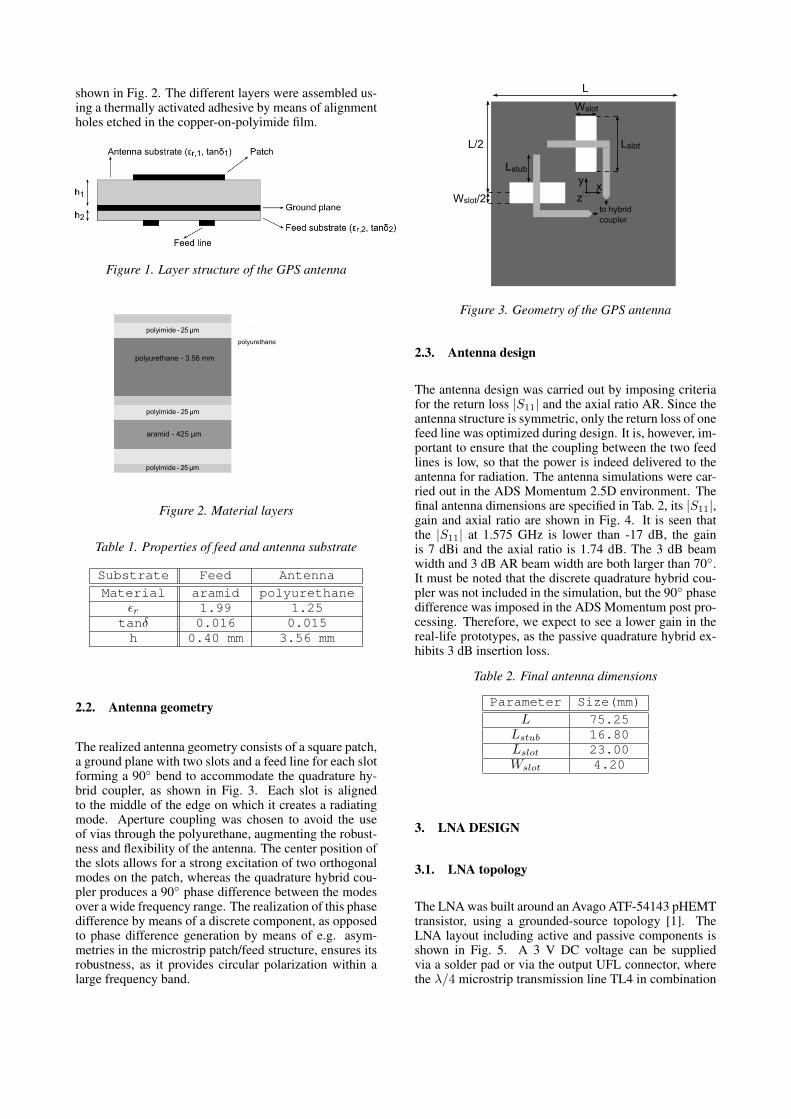
The realized antenna geometry consists of a square patch,a ground plane with two slots and a feed line for each slotforming a 90 bend to accommodate the quadrature hy-brid coupler, as shown in Fig. 3. Each slot is alignedto the middle of the edge on which it creates a radiatingmode. Aperture coupling was chosen to avoid the useof vias through the polyurethane, augmenting the robust-ness and flexibility of the antenna. The center position ofthe slots allows for a strong excitation of two orthogonalmodes on the patch, whereas the quadrature hybrid cou-pler produces a 90 phase difference between the modesover a wide frequency range. The realization of this phasedifference by means of a discrete component, as opposedto phase difference generation by means of e.g. asym-metries in the microstrip patch/feed structure, ensures itsrobustness, as it provides circular polarization within alarge frequency band.
L
Wslot/2
L/2
Lstub
Wslot
Lslot
xy
zto hybridcoupler
Figure 3. Geometry of the GPS antenna
2.3. Antenna design
The antenna design was carried out by imposing criteriafor the return loss |S11| and the axial ratio AR. Since theantenna structure is symmetric, only the return loss of onefeed line was optimized during design. It is, however, im-portant to ensure that the coupling between the two feedlines is low, so that the power is indeed delivered to theantenna for radiation. The antenna simulations were car-ried out in the ADS Momentum 2.5D environment. Thefinal antenna dimensions are specified in Tab. 2, its |S11|,gain and axial ratio are shown in Fig. 4. It is seen thatthe |S11| at 1.575 GHz is lower than -17 dB, the gainis 7 dBi and the axial ratio is 1.74 dB. The 3 dB beamwidth and 3 dB AR beam width are both larger than 70.It must be noted that the discrete quadrature hybrid cou-pler was not included in the simulation, but the 90 phasedifference was imposed in the ADS Momentum post pro-cessing. Therefore, we expect to see a lower gain in thereal-life prototypes, as the passive quadrature hybrid ex-hibits 3 dB insertion loss.
Table 2. Final antenna dimensions
Parameter Size(mm)
L 75.25Lstub 16.80Lslot 23.00Wslot 4.20
3. LNA DESIGN
3.1. LNA topology
The LNA was built around an Avago ATF-54143 pHEMTtransistor, using a grounded-source topology [1]. TheLNA layout including active and passive components isshown in Fig. 5. A 3 V DC voltage can be suppliedvia a solder pad or via the output UFL connector, wherethe λ/4 microstrip transmission line TL4 in combination

|S11|
AR
gain
1.5 1.6 1.71.4 1.8
-20
-15
-10
-5
-25
0
2
4
6
8
0
10
f (GHz)
Figure 4. Simulated gain, axial ratio and |S11|
with C10 forms a high impedance at the working fre-quency between the output and the 3 V bias pad. L2 andC9 provide additional AC blocking. The transistor gateis biased via the resistive voltage divider R3-R4 throughthe inductor L1. Bias to the drain is provided via the λ/4microstrip transmission line TL3 in combination with ca-pacitor C8. R1 provides a resistive termination at lowfrequencies, enhancing stability. R2 limits the gate cur-rent at high input power. Resistor R5 provides stabil-ity below 5 GHz. At higher frequencies stability is en-sured by providing a low impedance connection betweensource and ground. In- and output matching are realizedby capacitor-stub-capacitor filters formed by C1-TL1-C2and C6-TL2-C7.
C1C7C6
C2
C4
C3
C8
C9 C10
C5
R1
R2
R3 R4
R5
L1
L2
TL1
TL2
TL3
TL4
T1
OUT + 3V supply
Figure 5. LNA circuit
3.2. LNA design
The criteria imposed for the LNA design were a highgain, good in- and output matching and, of course, a lownoise figure. Since the LNA is placed in-between two50 Ω terminated devices and its in- and output will bematched to 50 Ω, the |S21| can be used as a gain measure.In- and output matching are performed using matchingnetworks, imposing a < -10 dB condition on both the
|S11| and |S22|. As for the noise figure, we aimed at avalue around 0.5 dB. Stability was taken into account bymeans of the stability factor K and the stability measureB1 [21]. For unconditional stability, the K factor shouldbe larger than 1 while the stability measure should be pos-itive. The passive LNA interconnections and transmis-sion lines were simulated in the ADS Momentum 2.5Denvironment, while the discrete active and passive com-ponents were simulated in the ADS circuit simulator. Thefinal components are listed in Tab. 3. The capacitors are0603 SMD parts from Murata and Johanson Technology,the coils are 0603 SMD parts from Coilcraft. The simu-lation results will be discussed in section 4.2, where theywill be compared with the measurement results.
Table 3. Used components and their values
Component Value Component Value
C1 30 pF R1 50 ΩC2 4.7 pF R1 1 kΩC3 220 pF R1 330 ΩC4,C5 6.8 pF R1 1.8 kΩC6 10 pF R1 120 ΩC7 22 pF L1,L2 10 nHC8 12 pF TL1 9.5 mmC9 100 nF TL2 12.75 mmC10 12 pF TL3,TL4 41.5 mm
3.3. Optional SAW filter
In the final layouts, the possibility to include an SAW fil-ter at the LNA input was provided. The EPCOS B-9080SAW filter was chosen [19]. This is a low insertion lossL1 band pass filter and provides additional signal sup-pression of out-of-band signals, such as DAB between1.452 GHz and 1.492 GHz or cellular signals in the DCS-1800 band. The LNA with SAW was not simulated, as nosimulation data was available for the SAW filter.
4. MEASUREMENTS
A passive and active version of the antenna were fabri-cated, as well as a standalone version of the LNA, as tomeasure the characteristics of the antenna and LNA ontheir own and compare these to the measurement resultsof the active antenna. The LNA and active antenna werefabricated in two versions: with and without SAW filter.Pictures of the active antenna prototype with SAW filterare shown in Fig. 6 and Fig. 7. The measurements wereperformed using the N5242 A PNA-X Vector NetworkAnalyzer from Agilent Technologies.
UFL connector (output + DC feed)
feed lines
copper-on-polyimide layer
discrete quadraturehybrid coupler
SAW filter
Figure 6. Picture of the antenna backside with LNA
copper-on-polyimide patch
polyurethane foam
Figure 7. Picture of the antenna front
4.1. Antenna measurements
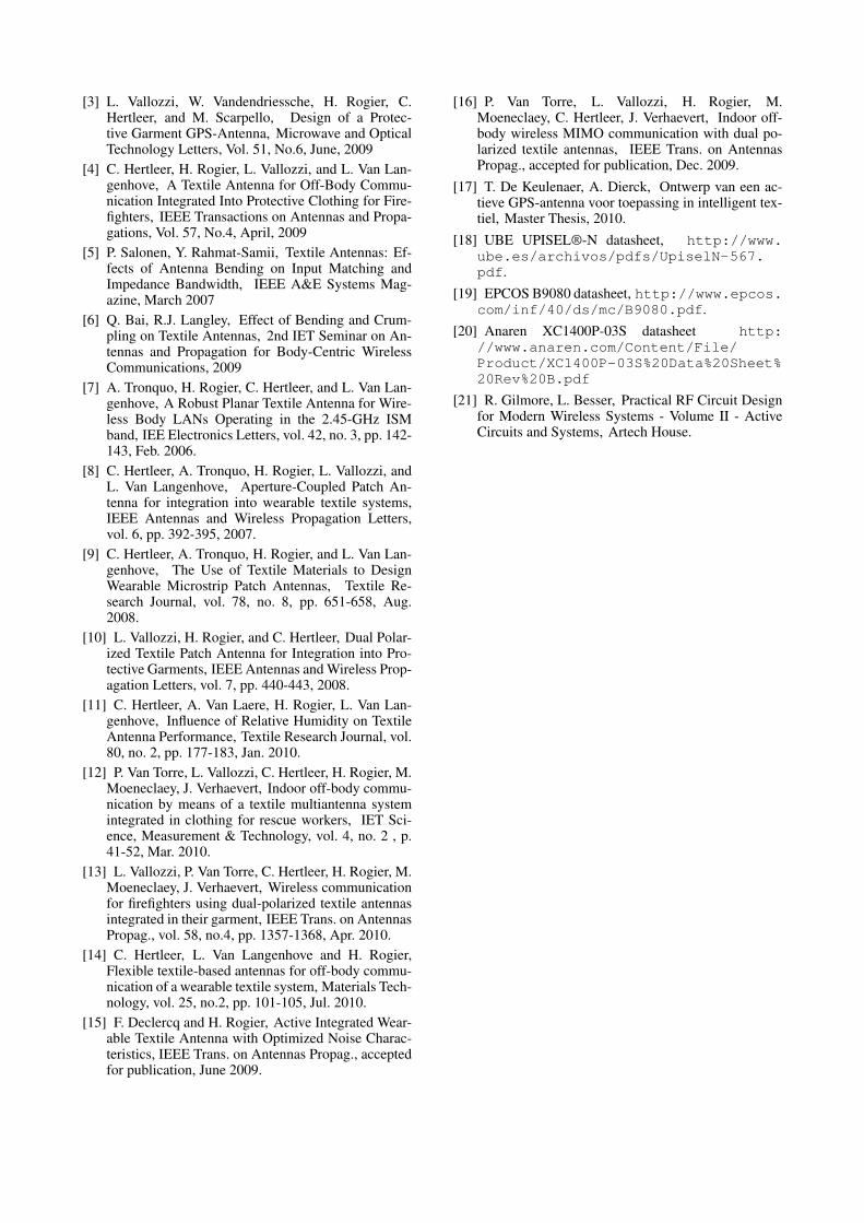
The radiation pattern of the passive antenna was mea-sured in both the XZ and the YZ plane, using a stan-dard gain horn in the anechoic chamber. Measurementswere also performed for an antenna covered by aramid,to analyze the effect of integration into a textile garment.The aramid layer had no noticeable influence on the an-tenna characteristics. The radiation patterns of the activeantenna were similar. The XZ and YZ patterns of thearamid covered passive antenna are shown in Fig. 8 and9. The antenna gain at 0 is 5 dBi. The gain, axial ra-tio and |S11| as a function of the frequency are shownin Fig. 10. When we compare this with the simulatedresults from Fig. 4, we clearly notice the effect of thediscrete quadrature hybrid coupler, more specifically thebroad 50 Ω match. The measured AR curve also behavesdifferently, providing a 3 dB axial ratio bandwidth that isless broadband than simulated. However, the 3 dB ARbandwidth remains sufficiently broad for GPS L1 opera-tion. At 1.575 GHz, the AR is 2.2 dB, which is higherthan simulated, but still well below 3 dB. The 3 dB beamwidth and 3 dB AR beam width are both larger than 70.
0
30
60
90
120
150
180
-150
-120
-90
-60
-30
Figure 8. Radiation pattern of the aramid covered pas-sive antenna in the XZ plane
0
180
60
90
150-150
-120
-60
-30
Figure 9. Radiation pattern of the aramid covered pas-sive antenna in the YZ plane
Figure 10. Measured gain, axial ratio and |S11| of thepassive antenna

4.2. LNA measurements
The two-port scattering parameters and noise figure of theLNA were measured both with and without SAW filter.From the measured S-parameters, K factor and stabilitymeasure B1 were calculated.
4.2.1. LNA without SAW filter
Measurement and simulation results of the LNA with-out SAW filter are shown in Fig. 11 to 13. The mea-sured |S21| at the L1 band center frequency is in goodagreement with the simulated value, both being about18.1 dB. The measured noise figure, being 0.545 dB, isalso in good agreement with the simulated value, whichwas 0.475 dB. Both measured and simulated |S12| (notshown in on graphs) are well below -20 dB. Less agree-ment is found between the measured and simulated |S11|and |S22|. The measured curves seem to be shifted up-wards to the right, all the more so for |S11|. At the L1band center frequency, the measured |S22| is still compa-rable to the simulated value and lower than -10 dB. Themeasured |S11| at this frequency, however, differs greatlyfrom the simulated value, and exceeds -10 dB. An ex-planation could be found in the difference between thesimulation and the measurement setup. During measure-ments, the LNA was interfaced by means of UFL connec-tors and cables. These were not taken into account duringthe simulation. Comparing the stability of the simulatedand the measured LNA, it is seen that the measured sta-bility factor K drops below 1 between 1 and 1.7 GHz,so unconditional stability in that frequency range is notensured. However, no instability was encountered dur-ing measurements and connection to a GPS receiver. Themeasured LNA power consumption is 84 mW.
1.1 1.2 1.3 1.4 1.5 1.6 1.7 1.8 1.91.0 2.0
5
10
15
20
0
25
1
2
3
4
0
5
f [GHz]
measured
simulated
Figure 11. Simulated and measured LNA |S21| and noisefigure
1.1 1.2 1.3 1.4 1.5 1.6 1.7 1.8 1.91.0 2.0
-20
-15
-10
-5
-25
0
-20
-15
-10
-5
-25
0
f (GHz)
measured
simulated
Figure 12. Simulated and measured LNA |S11| and |S22|
1 2 3 4 5 6 7 8 9 10 110 12
1
1E1
1E-1
1E2
1
2
3
4
5
6
7
8
9
0
10
f (GHz)
measured
simulated
B1
Figure 13. Simulated and measured LNA K factor andstability measure
4.2.2. LNA with SAW filter
Measurement results of the LNA with SAW filter areshown in Fig. 14 to 16. The effect of the SAW filter isclearly visible in the results, which show that the opera-tion of the LNA is limited to the SAW filter pass band.The |S21| and noise figure differ from the values for theLNA without SAW filter by about 1.5 dB, i.e. the inser-tion loss of the SAW filter. The |S11| and |S22| are withinspecifications, being less than -10 dB. The K factor andstability measure indicate that unconditional stability isguaranteed from 0 to 12 GHz.
4.3. Active antenna measurements
The gain, axial ratio and |S11| as a function of frequencyfor the active antenna with and without SAW filter areshown in Fig. 17 and Fig. 18. The total gain, consistingof the antenna and LNA gain, in the main radiation di-rection is 23.6 dB for the active antenna without SAWfilter and 21.5 dB for the active antenna with SAW fil-ter, which could be expected from the separate antennaand LNA measurements. The AR of the antenna withoutSAW has the same behavior as the passive antenna’s AR.It is, however, about 1 dB lower. This could be caused

1.1 1.2 1.3 1.4 1.5 1.6 1.7 1.8 1.91.0 2.0
-30
-20
-10
0
10
-40
20
1
2
3
4
5
6
7
8
9
0
10
f (GHz)
Figure 14. Measured LNA with SAW |S21| and noise fig-ure
1.1 1.2 1.3 1.4 1.5 1.6 1.7 1.8 1.91.0 2.0
-20
-15
-10
-5
-25
0
-20
-15
-10
-5
-25
0
f (GHz)
Figure 15. Measured LNA with SAW |S11| and |S22|
1 2 3 4 5 6 7 8 9 10 110 12
1
1E1
1E-1
1E2
1
2
3
4
5
6
7
8
9
0
10
f (GHz)
B1
Figure 16. Measured LNA with SAW K factor and stabil-ity measure
by small differences originating from the alignment pro-cess. The AR characteristic of the active antenna withSAW filter differs from the one without SAW. The band-pass nature of the SAW filter is clearly visible. The |S11|of the antenna without SAW is -9 dB. The |S11| of the an-tenna with SAW filter is -9.5 dB. Both antennas achieve a3 dB beam width and a 3 dB AR beam width larger than70.
|S11|
AR
total gain
1.45 1.50 1.55 1.60 1.65 1.70 1.751.40 1.80
-20
-15
-10
-5
-25
0
5
10
15
20
0
25
f [GHz]
Figure 17. Measured gain, axial ratio and |S11| of theactive antenna without SAW filter
|S11|
AR
total gain
1.55 1.601.50 1.65
-20
-15
-10
-5
-25
0
5
10
15
20
0
25
f [GHz]
Figure 18. Measured gain, axial ratio and |S11| of theactive antenna with SAW filter
5. CONCLUSIONS
The presented active antenna is able to cover the2.042 MHz wide GPS L1 band at 1.57542 GHz with acombined antenna and LNA gain of 23.6 dB, a noise fig-ure of 0.5 dB, an axial ratio of 0.7 dB and an |S11| of-9 dB for the antenna without SAW filter. The active an-tenna weight is 14 g. Upon connection of the active an-tenna to a GPS receiver, it provided us with better carrierto noise ratios than the off-the-shelf rigid active antennaprovided alongside the receiver.
REFERENCES
[1] A.J.Ward, AN-1222 High Intercept Noise Amplifierfor the 1850 - 1910 MHz PCS Band using the Agi-lent ATF-54143 Enhancement Mode PHEMT, Agi-lent Technologies, 2006.
[2] T.F. Kennedy, P.W. Fink, A.W. Chu, N.J. ChampagneII, G.Y. Lin, M.A. Khayat, Body-worn E-textile An-tennas: The Good, the Low-Mass, and the Confor-mal, IEEE Transactions on Antennas and Propaga-tions, Vol. 57, No.4, April, 2009
[3] L. Vallozzi, W. Vandendriessche, H. Rogier, C.Hertleer, and M. Scarpello, Design of a Protec-tive Garment GPS-Antenna, Microwave and OpticalTechnology Letters, Vol. 51, No.6, June, 2009
[4] C. Hertleer, H. Rogier, L. Vallozzi, and L. Van Lan-genhove, A Textile Antenna for Off-Body Commu-nication Integrated Into Protective Clothing for Fire-fighters, IEEE Transactions on Antennas and Propa-gations, Vol. 57, No.4, April, 2009
[5] P. Salonen, Y. Rahmat-Samii, Textile Antennas: Ef-fects of Antenna Bending on Input Matching andImpedance Bandwidth, IEEE A&E Systems Mag-azine, March 2007
[6] Q. Bai, R.J. Langley, Effect of Bending and Crum-pling on Textile Antennas, 2nd IET Seminar on An-tennas and Propagation for Body-Centric WirelessCommunications, 2009
[7] A. Tronquo, H. Rogier, C. Hertleer, and L. Van Lan-genhove, A Robust Planar Textile Antenna for Wire-less Body LANs Operating in the 2.45-GHz ISMband, IEE Electronics Letters, vol. 42, no. 3, pp. 142-143, Feb. 2006.
[8] C. Hertleer, A. Tronquo, H. Rogier, L. Vallozzi, andL. Van Langenhove, Aperture-Coupled Patch An-tenna for integration into wearable textile systems,IEEE Antennas and Wireless Propagation Letters,vol. 6, pp. 392-395, 2007.
[9] C. Hertleer, A. Tronquo, H. Rogier, and L. Van Lan-genhove, The Use of Textile Materials to DesignWearable Microstrip Patch Antennas, Textile Re-search Journal, vol. 78, no. 8, pp. 651-658, Aug.2008.
[10] L. Vallozzi, H. Rogier, and C. Hertleer, Dual Polar-ized Textile Patch Antenna for Integration into Pro-tective Garments, IEEE Antennas and Wireless Prop-agation Letters, vol. 7, pp. 440-443, 2008.
[11] C. Hertleer, A. Van Laere, H. Rogier, L. Van Lan-genhove, Influence of Relative Humidity on TextileAntenna Performance, Textile Research Journal, vol.80, no. 2, pp. 177-183, Jan. 2010.
[12] P. Van Torre, L. Vallozzi, C. Hertleer, H. Rogier, M.Moeneclaey, J. Verhaevert, Indoor off-body commu-nication by means of a textile multiantenna systemintegrated in clothing for rescue workers, IET Sci-ence, Measurement & Technology, vol. 4, no. 2 , p.41-52, Mar. 2010.
[13] L. Vallozzi, P. Van Torre, C. Hertleer, H. Rogier, M.Moeneclaey, J. Verhaevert, Wireless communicationfor firefighters using dual-polarized textile antennasintegrated in their garment, IEEE Trans. on AntennasPropag., vol. 58, no.4, pp. 1357-1368, Apr. 2010.
[14] C. Hertleer, L. Van Langenhove and H. Rogier,Flexible textile-based antennas for off-body commu-nication of a wearable textile system, Materials Tech-nology, vol. 25, no.2, pp. 101-105, Jul. 2010.
[15] F. Declercq and H. Rogier, Active Integrated Wear-able Textile Antenna with Optimized Noise Charac-teristics, IEEE Trans. on Antennas Propag., acceptedfor publication, June 2009.
[16] P. Van Torre, L. Vallozzi, H. Rogier, M.Moeneclaey, C. Hertleer, J. Verhaevert, Indoor off-body wireless MIMO communication with dual po-larized textile antennas, IEEE Trans. on AntennasPropag., accepted for publication, Dec. 2009.
[17] T. De Keulenaer, A. Dierck, Ontwerp van een ac-tieve GPS-antenna voor toepassing in intelligent tex-tiel, Master Thesis, 2010.
[18] UBE UPISEL®-N datasheet, http://www.ube.es/archivos/pdfs/UpiselN-567.pdf.
[19] EPCOS B9080 datasheet, http://www.epcos.com/inf/40/ds/mc/B9080.pdf.
[20] Anaren XC1400P-03S datasheet http://www.anaren.com/Content/File/Product/XC1400P-03S%20Data%20Sheet%20Rev%20B.pdf
[21] R. Gilmore, L. Besser, Practical RF Circuit Designfor Modern Wireless Systems - Volume II - ActiveCircuits and Systems, Artech House.