a wearable multi-modal bio-sensing system towards real...
TRANSCRIPT

0018-9294 (c) 2018 IEEE. Personal use is permitted, but republication/redistribution requires IEEE permission. See http://www.ieee.org/publications_standards/publications/rights/index.html for more information.
This article has been accepted for publication in a future issue of this journal, but has not been fully edited. Content may change prior to final publication. Citation information: DOI 10.1109/TBME.2018.2868759, IEEETransactions on Biomedical Engineering
1
A Wearable Multi-modal Bio-sensing SystemTowards Real-world Applications
Siddharth Student Member, IEEE, Aashish N. Patel Member, IEEE, Tzyy-Ping Jung Fellow, IEEE, and Terrence J.Sejnowski Life Fellow, IEEE
Abstract—Multi-modal bio-sensing has recently been used aseffective research tools in affective computing, autism, clinicaldisorders, and virtual reality among other areas. However, noneof the existing bio-sensing systems support multi-modality ina wearable manner outside well-controlled laboratory environ-ments with research-grade measurements. This work attemptsto bridge this gap by developing a wearable multi-modal bio-sensing system capable of collecting, synchronizing, recordingand transmitting data from multiple bio-sensors: PPG, EEG,eye-gaze headset, body motion capture, GSR, etc. while alsoproviding task modulation features including visual-stimulustagging. This study describes the development and integrationof the various components of our system. We evaluate thedeveloped sensors by comparing their measurements to thoseobtained by a standard research-grade bio-sensors. We firstevaluate different sensor modalities of our headset, namelyearlobe-based PPG module with motion-noise canceling for ECGduring heart-beat calculation. We also compare the steady-statevisually evoked potentials (SSVEP) measured by our shieldeddry EEG sensors with the potentials obtained by commerciallyavailable dry EEG sensors. We also investigate the effect of headmovements on the accuracy and precision of our wearable eye-gaze system. Furthermore, we carry out two practical tasks todemonstrate the applications of using multiple sensor modalitiesfor exploring previously unanswerable questions in bio-sensing.Specifically, utilizing bio-sensing we show which strategy worksbest for playing Where is Waldo? visual-search game, changesin EEG corresponding to true versus false target fixations inthis game, and predicting the loss/draw/win states through bio-sensing modalities while learning their limitations in a Rock-Paper-Scissors game.
Index Terms—Brain-Computer Interface (BCI), Bio-sensing,EEG, Pupillometry, Multi-modality, PPG, Eye-gaze, StimulusTagging, Gaming.
I. INTRODUCTION
IN recent years, there have been many advances in thefield of wearable bio-sensing. This trend has led to the
development of multiple wearable bio-sensors capable ofmeasuring galvanic skin response (GSR), photoplethysmogram(PPG), etc. integrated into portable form-factors such as smart-watches. The use of bio-signals for various applications suchas robotics [1], [2], mental health [3], affective computing [4],human-computer interaction [5], [6] etc. has been expanding
Siddharth and Aashish N. Patel are with the Department of Electrical andComputer Engineering, University of California San Diego, La Jolla, CA,92093 USA e-mail: [email protected], [email protected]
Tzyy-Ping Jung and Terrence J. Sejnowski are with Institute for NeuralComputation, University of California San Diego, La Jolla, CA, 92093 USA,e-mail: [email protected], [email protected]
c©2018 IEEE. Personal use of this material is permitted. However, permis-sion to use this material for any other purposes must be obtained from theIEEE by sending an email to [email protected].
throughout the past decade. During the same time, the conceptof using more than one bio-sensing modality has also gainedpopularity. This is primarily driven by the assumption thatthe limitations of a bio-sensor can be compensated by usinganother for specific applications. For example, since EEGprovides good temporal resolution but poor spatial resolutionit might be possible to use other modalities such as PPG andGSR to augment the performance in an emotion classificationtask rather than using EEG alone [7], [8].
Unfortunately, the integration of above-mentioned bio-sensing modalities is usually overlooked for more naturalisticresearch studies due to cost, bulk, and technical difficulty [9],[10]. A typical strategy used to measure multiple bio-signalsin the real-world is to buy various sensors and then extractdata from each of them separately. This setup, however, leadsto unwieldy subject preparation and increased post-processingsynchronization effort, both of which add sources of noiseand inconvenience. Specifically, no integrated headset has beenproposed to measure multiple bio-signals simultaneously in asynchronized manner. Without the possibility of simultaneousrecordings from multiple modalities, it is difficult, if notimpossible, to explore questions corresponding to changes inphysiology while performing actions in the real world.
The problem of not being able to collect data in real-worldenvironments is compounded by the lack of techniques toautomatically recognize and tag real-life events or stimuli. Thestandard process employed for stimulus tagging requires anindividual (experimenter) to manually tag the various stimulifrom frame to frame in a video stream. This process iscumbersome, time-consuming, and laborious. Furthermore, thestimulus onset is not measured with fine-resolution or is ill-defined in such setups [11], [12]. A solution is to track eye-gaze to infer the stimulus onsets [13]. This allows pinpointingof the visual region, but still requires stimulus tagging.
Additionally, there is a design element associated with thebio-sensors, which needs to be optimized for compactness andcost for any multi-modal bio-sensing system. Any such devicehas to be capable of synchronizing multiple data streams andshould be packaged in a compact form factor for easy use.For example, the use of wet electrodes for measuring EEG orelectrocardiogram (ECG), which may require placing sensorsover the chest, is undesirable for real-world setups. This studyaddresses the above limitations by designing novel research-grade bio-sensors capable of measuring physiological mea-surements in real-world environments with automatic visualtagging and integrating the sensors in the form of a compactwearable headset. This research also presents evaluation on

0018-9294 (c) 2018 IEEE. Personal use is permitted, but republication/redistribution requires IEEE permission. See http://www.ieee.org/publications_standards/publications/rights/index.html for more information.
This article has been accepted for publication in a future issue of this journal, but has not been fully edited. Content may change prior to final publication. Citation information: DOI 10.1109/TBME.2018.2868759, IEEETransactions on Biomedical Engineering
2
TABLE ICOMPARISON OF MULTI-MODAL BIO-SENSING SYSTEMS
Features This System iMotions [9] Microsoft [14] Biovotion [15] Teaergo [16] OpenBCI [17] Imperial College [18]
Sensing Modalities EEG, PPG,Eye-Tracking,Pupillometry
EEG, ECG,GSR, EMG,Eye-Tracking
PPG, GSR, SkinTemperature
PPG, GSR, SkinTemperature
EEG, EMG, GSR,Eye-Gaze, MotionTracking
EEG, EMG, ECG EEG, ECG
Fully integrated, self-contained module∗
Yes No, multiple mod-ules
Yes Yes No, multiple mod-ules
Yes No, multiple modules
WirelessSynchronization†
Yes Yes No No Yes No No
Automatic VisualStimuli Tagging
Yes No No No No No No
Noise canceling mea-sures
Yes (ANC, Shield-ing)
No No No No No No
Research grade‡ Yes Yes No No Yes Yes Yes
Performance Evalua-tion while in motion
Yes No Yes Yes Yes No No
∗Containing data acquisition, noise filtering, digitizing, transmission circuitry and battery.†Capable of synchronizing with any external sensor too while transmitting wirelessly.‡Capable of acquiring data with high bit resolution and high sampling rate.
two “real-world” experiment setups through the use of gamingtowards utilizing multiple sensor modalities. We show that pre-viously unexplored physiological questions can be addressedusing multiple sensor modalities.
II. PROPOSED SYSTEM AND RELATED WORK
We designed and evaluated a novel earlobe-based, high-resolution PPG sensor that is capable of measuring heart rateand heart-rate variability as well as providing raw PPG datafrom the earlobe. Using adaptive noise cancellation and inten-tional placement at the earlobe to minimize sensor movement,the PPG sensor is capable of minimizing motion noise. Wealso designed and evaluated novel dry EEG sensors capableof actively filtering the EEG signals by shielding themselvesfrom ambient electrostatic noise. These EEG sensors are usedwith a high-sampling and ultra-low-noise analog to digitalconverter (ADC) module. We also designed and evaluateda dual-camera-based eyeglass capable of measuring eye-gaze(overlaid on the subject’s field of view), pupillometry, fixa-tions, and saccades. Data acquisition and synchronization fromall these sensors is done using an embedded system. Thesedata streams can then be saved on the device or wirelesslytransmitted in real-time for visualization and analysis. Theframework is designed to automatically tag visual stimuli inreal-world scenarios with subject’s eye-gaze over the variousbio-sensing modalities. Finally, the framework is scalable suchthat it can be expanded to support other bio-sensing modalitiesfrom the market. To the best of our knowledge, this is the onlymulti-modal bio-sensing system capable of working with sucha wide range of research-grade sensors.
Table I compares our system with many existing state-of-the-art bio-sensing systems. Clearly, we can see that in allcategories our system is more comprehensive and flexiblethan all the existing bio-sensing systems. The lack of costcomparison in the Table is because many of the systems
including ours have not been commercialized into products.Hence, it is not a fair comparison to evaluate the retail pricesof select systems with the fabrication costs of others.
In real-world applications, PPG has been substituted forECG due to the ease it offers in measuring heart rate. It doesnot require using wet electrodes over the chest and can easilybe integrated onto watches or armbands [10], [19]. But, it hasits own limitations. First, most of the available PPG sensors donot have sampling rate high enough and fine ADC resolutionto measure heart-rate variability (HRV) in addition to heartrate (HR). HRV has been shown to be a good measure ofemotional valence and physiological activity. Secondly, PPGsensors over the arm or wrist tend to be noisy because of theconstant movements of the limbs while performing real-worldtasks. On the other hand, PPG systems designed for the earlobealso suffer from noise due to walking or other head/neckmovements [19]. In the rare case when noise filtering is usedin PPG, the hardware design is bulky due to the large size ofthe circuit board used in the setup [20].
EEG sensors come in dry or wet-electrode based configu-rations. The wet electrodes either require the application ofgel or saline water during the experiment and hence are notideal outside laboratory environments [21]. The dry electrodesusually do not have a long service life since they are generallymade of Ag/AgCl or gold (Au) coating over a metal, plasticor polymer, which tend to wear off [22], [23]. Furthermore,coating Ag/AgCl is a costly electrochemical process.
Eye-gaze tracking systems tend to be bulky and may evenrequire the subject to place his/her face on a chin rest [24],[25]. Even when they are compact, these systems are notmobile and the subject has to be constantly in its field of view[26]. These limitations restrict their use outside well-controlledlaboratories, where illumination varies and the subject is mo-bile at all times. Furthermore, all such systems only measureeye-gaze as being pointed over a display monitor and not in

0018-9294 (c) 2018 IEEE. Personal use is permitted, but republication/redistribution requires IEEE permission. See http://www.ieee.org/publications_standards/publications/rights/index.html for more information.
This article has been accepted for publication in a future issue of this journal, but has not been fully edited. Content may change prior to final publication. Citation information: DOI 10.1109/TBME.2018.2868759, IEEETransactions on Biomedical Engineering
3
the real world. They are unable to overlay the gaze over thesubject’s view if the display screen is not in his/her field ofview. The solution is to use head-mounted eye-gaze systemsbut they tend to use a laptop instead of a small embeddedsystem for processing and viewing the camera streams [27].Thus, the laptop has to be carried in a bag, restricting thesubject’s freedom of movement.
To tag the stimuli with various bio-sensing modalities, thenorm has been to use a key/button press, fix the onset andorder of stimuli on a display, or time it with a particularevent etc. [11], [12] But, in real-world scenarios, such methodseither cannot be used due to the mobile nature of the setupor induce a sense of uncertainty which has to be removedby manual tagging. Such manual tagging is laborious andtime-consuming. The only viable solution is to tag stimuliautomatically after recognizing them in the subject’s field ofview. However, it lacks the knowledge of whether the subjectwas actually focusing on the stimuli or rather was looking atsome other areas in his/her field of view.
The existing multi-modal experimental setups are tethered,are not compact and tend to just attach various sensors onthe subject, which are then connected to one or more dataacquisition systems [4], [9]. This further reduces the mobilityfor experiments outside laboratories. The use of independentclock for each of the different modality complicates theissue of synchronizing the various modalities. For real-timedisplay, transmitting data streams from these sensors over Wi-Fi or Bluetooth may introduce varying latency. Thus, the onlysolution is to design a closely packed hardware system [28],which synchronizes the various data streams while acquiringthem in a wired manner and using only one clock (that ofthe embedded system itself). The synchronized streams canthen be either recorded or sent to a display screen whichdoes not affect either the compact nature of hardware orsynchronization in software framework. In the next section,we present the various sensors and methods developed by usto address the above limitations.
III. SYSTEM OVERVIEW
This section details the development of each of the sensormodules incorporated in our system with its features and theembedded system used for their integration.
A. Earlobe-based PPG Sensor
We developed an earlobe-based PPG sensor. The PPGsensor module is very compact (1.6 x 1.6 x 0.6 cm) andsandwiched to the earlobe using two small neodymium mag-nets. The PPG sensor module (Fig. 1) houses an Infrared (IR)emitter-detector (Vishay TCRT 1000) for measuring PPG, a3-axis accelerometer (Analog Devices ADXL 335), a high-precision (16-bit) and high-sampling rate (100 Hz.) ADC(Texas Instruments ADS 1115), and a third-order analog high-gain band-pass filter (BPF, cutoff 0.8 - 4 Hz using threeMicrochip MCP6001 op-amps).
This PPG signal is then amplified using the high-gain band-pass filter and a relevant frequency band is extracted. Thefiltered PPG data along with accelerometer’s data are digitized
Fig. 1. The miniaturized PPG sensor with a scale reference. (A) 3-axisaccelerometer, (B) 100 Hz 16-bit ADC, (C) IR emitter and receiver, and (D)a third-order filter bank.
using the ADC before transmission. Thus, the PPG moduleis capable of filtering the signal on-board (despite being sominuscule in size) and converting the signal to a digital formatfor the calculation of heart rate and heart-rate variability. Theonboard accelerometer serves two purposes. First, it can beused to measure and monitor head movements because thesensor is fixed on the earlobe with reference to the positionof the subject’s face. Secondly, the accelerometer provides ameasure of noise due to motion and removes it from the PPGsignal using an adaptive noise-cancellation (ANC) filter. Thefilter [29] can be implemented inside our embedded system(section E) in real-time. The filter works by constructing amodel of noise due to motion (such as while walking) fromthe reading of the accelerometer and reconstructing the noise-removed PPG signal.
B. EEG Sensors and Data Acquisition
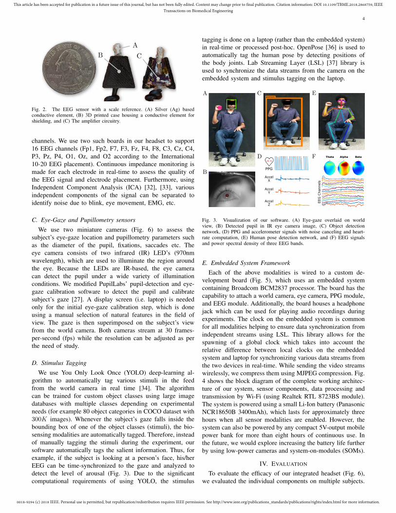
We developed novel dry EEG sensors (Fig. 2) that can beeasily adjusted under the hairs to measure EEG signals fromthe scalp. These EEG sensors consist of a highly conductive el-ement made from silver (Ag) epoxy (electrical resistivity 0.007Ω·cm). This silver-epoxy-based conductive element providesthe sensor a long life since the silver does not wear off as fastas it does on EEG sensors coated with Ag/AgCl. The sensoralso has an on-board OpAmp (Texas Instruments TLV 2211)in a voltage-follower configuration to shield the EEG signalfrom noise by increasing the signal-to-noise ratio (SNR) of theEEG signal. Furthermore, the sensor is enclosed in a Faradaycage made of conductive copper foil tape. This shielding isused to remove external noise from the environment beforethe signal is digitized. For subjects with dense hair, a drop ofsaline water can be added to increase the conductance betweenthe sensing element and the subject’s scalp.
For converting the analog noise-removed EEG signal to adigital format, we designed an assembly for fine resolution(24-bit), high-sampling rate (up to 16k samples/second), ultra-low input referred noise (1 µV) ADC (Texas Instruments ADS1299). Our assembly is such that it employs a low-pass filterbefore the signal goes into the ADC, whose parameters such assampling rate, bias calculation, internal source current ampli-tude for impedance measurement etc. can be controlled by thesoftware [30], [31]. The assembly can support up to eight EEGchannels (Fig. 5F) whereas the design of the board is such thatmultiple boards can be stacked to accommodate more EEG
0018-9294 (c) 2018 IEEE. Personal use is permitted, but republication/redistribution requires IEEE permission. See http://www.ieee.org/publications_standards/publications/rights/index.html for more information.
This article has been accepted for publication in a future issue of this journal, but has not been fully edited. Content may change prior to final publication. Citation information: DOI 10.1109/TBME.2018.2868759, IEEETransactions on Biomedical Engineering
4
Fig. 2. The EEG sensor with a scale reference. (A) Silver (Ag) basedconductive element, (B) 3D printed case housing a conductive element forshielding, and (C) The amplifier circuitry.
channels. We use two such boards in our headset to support16 EEG channels (Fp1, Fp2, F7, F3, Fz, F4, F8, C3, Cz, C4,P3, Pz, P4, O1, Oz, and O2 according to the International10-20 EEG placement). Continuous impedance monitoring ismade for each electrode in real-time to assess the quality ofthe EEG signal and electrode placement. Furthermore, usingIndependent Component Analysis (ICA) [32], [33], variousindependent components of the signal can be separated toidentify noise due to blink, eye movement, EMG, etc.
C. Eye-Gaze and Pupillometry sensors
We use two miniature cameras (Fig. 6) to assess thesubject’s eye-gaze location and pupillometry parameters suchas the diameter of the pupil, fixations, saccades etc. Theeye camera consists of two infrared (IR) LED’s (970nmwavelength), which are used to illuminate the region aroundthe eye. Because the LEDs are IR-based, the eye cameracan detect the pupil under a wide variety of illuminationconditions. We modified PupilLabs’ pupil-detection and eye-gaze calibration software to detect the pupil and calibratesubject’s gaze [27]. A display screen (i.e. laptop) is neededonly for the initial eye-gaze calibration step, which is doneusing a manual selection of natural features in the field ofview. The gaze is then superimposed on the subject’s viewfrom the world camera. Both cameras stream at 30 frames-per-second (fps) while the resolution can be adjusted as perthe need of study.
D. Stimulus Tagging
We use You Only Look Once (YOLO) deep-learning al-gorithm to automatically tag various stimuli in the feedfrom the world camera in real time [34]. The algorithmcan be trained for custom object classes using large imagedatabases with multiple classes depending on experimentalneeds (for example 80 object categories in COCO dataset with300K images). Whenever the subject’s gaze falls inside thebounding box of one of the object classes (stimuli), the bio-sensing modalities are automatically tagged. Therefore, insteadof manually tagging the stimuli during the experiment, oursoftware automatically tags the salient information. Thus, forexample, if the subject is looking at a person’s face, his/herEEG can be time-synchronized to the gaze and analyzed todetect the level of arousal (Fig. 3). Due to the significantcomputational requirements of using YOLO, the stimulus
tagging is done on a laptop (rather than the embedded system)in real-time or processed post-hoc. OpenPose [36] is used toautomatically tag the human pose by detecting positions ofthe body joints. Lab Streaming Layer (LSL) [37] library isused to synchronize the data streams from the camera on theembedded system and stimulus tagging on the laptop.
Fig. 3. Visualization of our software. (A) Eye-gaze overlaid on worldview, (B) Detected pupil in IR eye camera image, (C) Object detectionnetwork, (D) PPG and accelerometer signals with noise canceling and heart-rate computation, (E) Human pose detection network, and (F) EEG signalsand power spectral density of three EEG bands.
E. Embedded System FrameworkEach of the above modalities is wired to a custom de-
velopment board (Fig. 5), which uses an embedded systemcontaining Broadcom BCM2837 processor. The board has thecapability to attach a world camera, eye camera, PPG module,and EEG module. Additionally, the board houses a headphonejack which can be used for playing audio recordings duringexperiments. The clock on the embedded system is commonfor all modalities helping to ensure data synchronization fromindependent streams using LSL. This library allows for thespawning of a global clock which takes into account therelative difference between local clocks on the embeddedsystem and laptop for synchronizing various data streams fromthe two devices in real-time. While sending the video streamswirelessly, we compress them using MJPEG compression. Fig.4 shows the block diagram of the complete working architec-ture of our system, sensor components, data processing andtransmission by Wi-Fi (using Realtek RTL 8723BS module).The system is powered using a small Li-Ion battery (PanasonicNCR18650B 3400mAh), which lasts for approximately threehours when all sensor modalities are enabled. However, thesystem can also be powered by any compact 5V-output mobilepower bank for more than eight hours of continuous use. Inthe future, we would explore increasing the battery life furtherby using low-power cameras and system-on-modules (SOMs).
IV. EVALUATION
To evaluate the efficacy of our integrated headset (Fig. 6),we evaluated the individual components on multiple subjects.

0018-9294 (c) 2018 IEEE. Personal use is permitted, but republication/redistribution requires IEEE permission. See http://www.ieee.org/publications_standards/publications/rights/index.html for more information.
This article has been accepted for publication in a future issue of this journal, but has not been fully edited. Content may change prior to final publication. Citation information: DOI 10.1109/TBME.2018.2868759, IEEETransactions on Biomedical Engineering
5
Fig. 4. Overview of the integrated system architecture.
Fig. 5. Embedded System (A) Power circuitry, (B) World camera connector,(C) PPG connector, (D) Audio jack connector, (E) Eye camera connector,(F) EEG sensors connector and ADC module, (G) Wi-Fi module, and (H)Microprocessor module
Below we provide the evaluation results for each of thecomponents. We then designed two experiment scenarios usingcommonly played games: “Where is Waldo?” and “Rock-Paper-Scissors” during which we collect multi-modal datausing the evaluated sensor modalities. We then show how afusion of information from individual modalities can providenew insights into human physiology. The human trial portionof our study was reviewed and approved by an IRB ofUniversity of California San Diego, and all subjects providedinformed consent.
A. The evaluation of Sensor Modalities
We use multiple benchmarks to evaluate each of the sensorsdeveloped in this study. The apparatus designed for evaluatingthese sensors also include various types of head and body
movements to assess the effect of our noise-canceling tech-niques.
1) Earlobe PPG: The earlobe PPG module was evaluatedduring rest and active conditions. In particular, the feature ofinterest, heart rate, was measured while subjects were sittingand walking in place. The PPG sensor was placed on theearlobe as in Fig. 6 and measured the changes in bloodvolume at the sampling rate of 100 Hz. Simultaneously, thebaseline was collected using an EEG/ECG acquisition systemsampled at 1 KHz from the Institute of Neural Engineering,Tsinghua University, China. Three electrodes were placed onthe subjects’ chest over the heart, and on either side of theribs.
Fig. 6. Integrated Headset (A) World camera, (B) EEG Sensors, (C) Battery,(D) EEG Reference Electrode, (E) Eye Camera, (F) Earlobe PPG Sensor, (G)Headphone/speaker connector, and (H) Embedded System (The subject gaveconsent to use his face for publication)
Six subjects participated in eight different trials: four sittingand four walking, during which their ECG and PPG datawere simultaneously measured. In each trial, two minutes ofdata were collected. For the walking condition, subjects were

0018-9294 (c) 2018 IEEE. Personal use is permitted, but republication/redistribution requires IEEE permission. See http://www.ieee.org/publications_standards/publications/rights/index.html for more information.
This article has been accepted for publication in a future issue of this journal, but has not been fully edited. Content may change prior to final publication. Citation information: DOI 10.1109/TBME.2018.2868759, IEEETransactions on Biomedical Engineering
6
instructed to walk-in-place at a regular rate and ANC wasperformed to remove motion noise. We used a peak detectionalgorithm to find the heart beats in both signals for countingthe heart rate.
Fig. 7 shows the working of the 10th order ANC filterutilized on a 10-second interval of PPG data while walking.The original PPG data (in blue) in Fig. 7A are clipped at thetop because a third order high-gain band-pass filter was usedthus amplifying the signal and making it easier to distinguishthe peaks in PPG. As we can see from Fig. 7A, the number ofpeaks in the original waveform is computed to be 20, whichis incorrect as the waveform is distorted. We then use themeasure of the noise from vertical acceleration (Fig. 7B) forthe ANC filter. Noise-removed PPG waveform with the use ofANC filter is shown in Fig. 7A and as expected the erroneouspeaks are eliminated, giving the total number of peaks as 17.
Fig. 7. Comparison of the 10-second waveforms from the earlobe PPG sensorbefore and after ANC during walking. (A) PPG without and after noise-cancellation (B) Vertical acceleration used as the noise measure.
We then performed Bland-Altman analysis [38], which isa general and effective statistical method for assessing theagreement between two clinical measurements to comparethe heart rate obtained by our PPG module to the true heartrate computed using the high-resolution ECG signal. Fifteen-second trials were used to calculate the HR using the peak-detection algorithm. Fig. 8A shows the result of the Bland-Altman analysis while the subjects were sitting. As we cansee from the figure, most of the trials are between the Mean± 1.96SD agreement threshold for both, with and withoutusing ANC. Further, we see that using ANC decreases theagreement threshold, making the two signals adhere to moreconformity. We see similar results for the trials when subjectswere walking (Fig. 8B) and again using ANC makes the HRmeasures from the two signals more agreeable. Furthermore,
for both cases, the trials from the two signals were almostalways in agreement, indicating that our earlobe PPG moduleis capable of measuring heart rate with high accuracy.
Fig. 8. PPG vs. ECG Bland-Altman Evaluation (Blue- Before ANC, Red-After using ANC) (A) While sitting and (B) While walking. Heart-ratecomputed by ANC filtered PPG conforms more closely to the true heart-rate.
2) Eye Gaze Evaluation: The performance of the pairedeye-pupil monitoring and world-view cameras in measuringeye gaze were evaluated using a structured visual task tomeasure precision and accuracy during use. We measured thegaze accuracy and precision for subjects following calibration(an ideal setting) and after head movements (a real-world use).In this task, we asked the subjects to calibrate their eye gazeusing nine targets which appeared on a screen 2.5 feet awayfrom them (such that >90% of the camera’s field of viewwas composed of the task-screen). For six subjects, we used aseries of 20 unique targets randomly distributed on the screento account for the majority of their field of view. Thus, thiscomposed the accuracy and precision measurements just aftercalibration. We then asked the participants to move their headnaturally for 30 seconds without removing the headset. Thisaction was designed to simulate the active head-movementscenarios when wearing the headset because usually the gazeperformance is not reported after the subject has moved fromhis/her position. Similar to the above task, we asked thesubjects to again gaze at 20 different points appearing on thescreen to assess the gaze performance after head movements.

0018-9294 (c) 2018 IEEE. Personal use is permitted, but republication/redistribution requires IEEE permission. See http://www.ieee.org/publications_standards/publications/rights/index.html for more information.
This article has been accepted for publication in a future issue of this journal, but has not been fully edited. Content may change prior to final publication. Citation information: DOI 10.1109/TBME.2018.2868759, IEEETransactions on Biomedical Engineering
7
The above process was repeated three times for each subject.Importantly, we did not use any chin rest during or aftercalibration so that gaze performance is measured with naturalhead and body movements.
Fig. 9. (A) Gaze accuracy (average angular offset between fixation locationsand corresponding targets) evaluation and (B) Gaze precision (root-mean-square of the angular distance between successive samples during fixation)evaluation. For both metrics, this system performs as well or better than suchexisting ones.
The accuracy is measured as the average angular offset -distance in degrees of the visual angle - between fixationlocations and the corresponding fixation targets. Fig. 9A showsthe gaze accuracy obtained before and after head movements.The mean gaze accuracy over all the trials was found to be 1.21degrees without and 1.63 degrees after head movements. Thedecrease in gaze accuracy after head movements is expectedbecause the headset’s position is displaced albeit by a smallvalue. For all the subjects, the mean gaze accuracy was mostlyless than 2 degrees and the mean performance drifts only 0.42degree, which is significantly less than 1-2 degree drift incommercially available eye-gaze systems [24]. The precisionis measured as the root-mean-square of the angular distancebetween successive samples during a fixation. Fig. 9B showsthe results of the angular precision for all the subjects. Themean angular precision was found to be 0.16 and 0.14 beforeand after head movements respectively. As is clear from thefigure, the degree of visual angle is almost always within therange of ±0.15. Furthermore, the precision has a mean shiftpost head movement of only 0.2, indicating a minimal angulardistance shift comparable to existing systems.
3) EEG Sensors Evaluation: For the evaluation of our EEGsensors, the comparison was two-fold. First, we comparedour EEG sensor with the state-of-the-art dry EEG sensors by
Cognionics [23] to evaluate the signal correlation achievedusing the two types of sensors. This also proves to be a testof whether our EEG sensors are actually acquiring EEG asopposed to just electromagnetic noise, and if they are ableto shield themselves from ambient noise in the environment.Second, we evaluated our sensors on a steady-state visuallyevoked potentials (SSVEP) BCI task to evaluate their perfor-mance in measuring various frequencies during standard use.
Fig. 10. (A) A comparison of 4-second EEG signals acquired by the proposedand Cognionics dry EEG sensors and (B) Correlation score between the EEGrecorded from the two sensors. Recordings from both the sensors show veryhigh correlation.
For the SSVEP testing, we used five of our EEG sensorsplaced at T5, O1, Oz, O2, and T6 sites according to thestandard EEG 10-20 system. The location over and near theoccipital lobe was chosen to evaluate the performance of oursensors because the SSVEPs in response to repetitive visualstimuli of different frequencies are strongest over the occipitallobe. Ten subjects participated in this experiment constitutingthree trials of ten random numbers each to be typed usingan SSVEP-based keypad on a mobile tablet (Samsung GalaxyS2) with an EEG sampling rate of 500Hz. The frequenciesof the 12 stimuli on the keypad (BCI speller) varied between9-11.75 Hz with increments of 0.25Hz. This fine resolutionin increment was chosen to assess the capability of sensorsin distinguishing between minutely varying frequencies. Thestimulus presentation time was 4 seconds with an interval of1 second of a blank screen between two consecutive stimuli.We only used the middle 2 seconds of data from each trial forSSVEP analysis. To compare the signal quality obtained fromthe two types of sensors, we used Cognionics sleep headbandto acquire EEG from one Cognionics sensor at the temporallobe and one of our sensors next to it. The location was chosenso that hairs on the scalp are present around the sensors.
Fig. 10A plots 4-second of EEG data acquired by the twosensors where a high correlation between the two signals isevident and almost always they follow a pattern. Fig. 10Bplots the correlation of a subset of 12 of the total trials.The correlations between the EEG signals acquired by thetwo different sensors were very high (the mean correlation
0018-9294 (c) 2018 IEEE. Personal use is permitted, but republication/redistribution requires IEEE permission. See http://www.ieee.org/publications_standards/publications/rights/index.html for more information.
This article has been accepted for publication in a future issue of this journal, but has not been fully edited. Content may change prior to final publication. Citation information: DOI 10.1109/TBME.2018.2868759, IEEETransactions on Biomedical Engineering
8
reached 0.901), indicating that the dry EEG sensor developedin this study is capable of measuring EEG signals from thehair-covered scalp areas.
Fig. 11. SSVEP accuracy plot for 0.25Hz increments in stimulus frequencies.Even for small increments of 0.25 Hz we see high SSVEP accuracy acrosssubjects.
As mentioned above, each subject needed to ‘type’ ten digitsin each of the three trials. We computed the SSVEP classifi-cation performance (Fig. 11) using the filter-bank correlationanalysis [39], [40]. This method does not require any trainingand is capable of working in real time. As mentioned above,we only used the middle two seconds of EEG data during the4-second stimulus presentation for evaluation. For almost allthe subjects, the performance of SSVEP accuracy was verygood (∼80% accuracy). There were some expected variationsbecause it is well known that the signal-to-noise ratio ofSSVEPs varies among individuals. The mean performanceacross all the subjects was 74.23%.
B. Multi-modal evaluation in “real-world” scenarios
We designed two experiments in which ten subjects partici-pated to play two games. For the “Where is Waldo?” game, the30th anniversary book of the series was used which containsthirteen different scenes (trials) in which the target (“Waldo”)has to be searched for. This experiment scenario was chosenbecause it allows for analyzing gaze-related fixations andpatterns. While searching for the target, many non-targets arepresent and hence target vs. non-target event-related potential(ERP) can also be assessed. The book was placed at a distanceof about 20 inches from the subjects who were seated andequipped with the sensor modalities mentioned above. Thesubjects were asked to search for the target without any timeconstraints. The researcher pressed a button before each trialand asked the subjects to start searching for the target. Thesubject conveyed that s/he has found the target verbally bysaying “Found”. Between each trial, the researcher flipped thepage of the book to the next scene.
In the “Rock-Paper-Scissors” game, the researcher wasseated in front of the subject (see Fig. 3A). A sound beep every17 seconds signaled the start of a trial. For each subject, thegame was played for 50 trials. The first two seconds afterthe sound beep were used to play the game whereas nextfifteen seconds the subject was asked to rest. The subject wasinstructed to only play the game from his/her wrist and nottwist the whole arm to avoid any headset movement. During
the game-play, motivational phrases such as “Come on! Youcan still win.”, “Watch out! I will now make a comeback”,etc. were utilized to ensure continual subject motivation. Aftereach trial, the researcher marked the outcome (win/loss/draw)for the subject by pressing a button. The choice of thisgame was made to analyze the changes in human physiology,particularly EEG and cardiac signals during the perceptionof winning/losing a game. These changes might be closer topositive/negative valence in emotional states but much morereliable since winning/losing are independent of one’s likesand dislikes that influences his/her emotions.
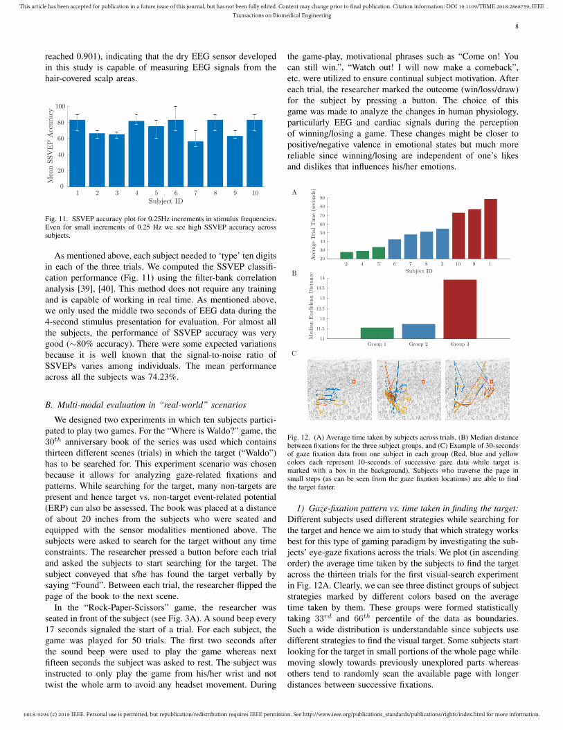
Fig. 12. (A) Average time taken by subjects across trials, (B) Median distancebetween fixations for the three subject groups, and (C) Example of 30-secondsof gaze fixation data from one subject in each group (Red, blue and yellowcolors each represent 10-seconds of successive gaze data while target ismarked with a box in the background). Subjects who traverse the page insmall steps (as can be seen from the gaze fixation locations) are able to findthe target faster.
1) Gaze-fixation pattern vs. time taken in finding the target:Different subjects used different strategies while searching forthe target and hence we aim to study that which strategy worksbest for this type of gaming paradigm by investigating the sub-jects’ eye-gaze fixations across the trials. We plot (in ascendingorder) the average time taken by the subjects to find the targetacross the thirteen trials for the first visual-search experimentin Fig. 12A. Clearly, we can see three distinct groups of subjectstrategies marked by different colors based on the averagetime taken by them. These groups were formed statisticallytaking 33rd and 66th percentile of the data as boundaries.Such a wide distribution is understandable since subjects usedifferent strategies to find the visual target. Some subjects startlooking for the target in small portions of the whole page whilemoving slowly towards previously unexplored parts whereasothers tend to randomly scan the available page with longerdistances between successive fixations.

0018-9294 (c) 2018 IEEE. Personal use is permitted, but republication/redistribution requires IEEE permission. See http://www.ieee.org/publications_standards/publications/rights/index.html for more information.
This article has been accepted for publication in a future issue of this journal, but has not been fully edited. Content may change prior to final publication. Citation information: DOI 10.1109/TBME.2018.2868759, IEEETransactions on Biomedical Engineering
9
To exclude the data associated with eye blinks (i.e. eyeclosures) we imposed a confidence threshold of 70% inour pupil detection algorithm. Then, we used the Euclideandistance of 25 pixels as the maximum inter-sample distanceand 500 milliseconds as the minimum fixation duration to findall the fixations associated with the trials for all the subjects.We then computed the median (more robust than mean since asingle large distance between successive fixations would skewthe mean) distance between successive fixations for the threegroups of subjects and plot it in Fig. 12B. The median distancebetween successive fixations tends to increase in the samemanner for the three groups as the average time taken by themincreases. Fig. 12C shows an example of 30-seconds of gazedata of one subject each from the three groups. As is clearfrom these figures, the subjects in Group 1 tend to search forthe target in small sections of the page whereas the subjects inGroup 3 search for the target randomly across the whole page.Because subjects in Group 1 were able to find the target in theleast time (on average), we believe that for “Where is Waldo?”game the best strategy is to focus on small portions of the pagerather than searching for the target randomly across the wholepage. It was impossible to gauge this insight without the useof eye-gaze tracker in which the subjects’ gaze can be overlaidon the image from the world camera in addition to detectingthe pupil’s location with another camera.
Fig. 13. FRP plot of two EEG channel locations (A) Fz and (B) Oz. Target-fixated gaze FRP has much clear response than false-fixated gaze FRP.
2) Fixation-related Potentials (FRP) Analysis: EEG cor-responding to fixations to the targets and non-targets whilesearching for the target in the “Where is Waldo?” gameshould represent distinct FRPs associated with the change inphysiology. To discover this relationship, for each trial, weband-pass-filtered the EEG data within the trial between 1-30 Hz. We take the mean of 200ms of data before eachfixation as the baseline and subtract it from one-second ofpost-fixation EEG data to remove the variations in amplitude.We then calculated the FRP by averaging the data across thetrials and subjects for all fixations greater than or equal to onesecond. We expect to see distinct FRPs for targets and non-targets. Fig. 13 plots the averaged FRPs for Fz and Oz EEGchannels. The FRPs show distinct variations after the onsetof the fixations at zero seconds; the characteristic large peakat 200ms i.e. VPP and the trough between 200 and 400msi.e. N2 are consistent with the earlier findings that VPP andN2 components are associated with the face stimuli [41], [42].Furthermore, a large P3 response almost at the rightmost part
of the plot is associated with decision making and is clearlymuch larger for the target than the non-targets [43]. This isunderstandable because while searching for the target’s face,there are many non-targets with the similar face and clothingas the true target. When the subject first fixated on the truetarget, it takes time for him/her to assure it is indeed the truetarget. The slightly smeared nature of the P3 response is likelydue to the fact that the latency of the P3 can vary across trialsand individuals and the FPRs are time-locked to the onset offixation, which is dependent on at what instant the fixation isdetected by the algorithm since the pupil is continuously inmotion. Our results show that combining eye-gaze and EEGprovides insight into the search patterns and their effects onthe EEG in a visual-search task. Another significant aspect ofour apparatus was to use the book in a naturalistic setup, whichallows unconstrained head/body movements rather than askingthe subjects search the face in front of a computer screen withtheir head positioned on a chin-rest.
Fig. 14. Mean HRV variation across subjects arranged in ascending order ofnumber of trials won.
3) Variation across HRV during win/loss: HRV can be areliable indicator of human emotions and mental states [8]and we wanted to see the variation across the subjects forthe trials they won versus the ones they lost in the “Rock-Paper-Scissors” game. We computed HRV using the pNN50algorithm [44] from 15-seconds of data for each trial. Fig.14 shows the variation in HRV for all the subjects arrangedby the number of trials won by them in ascending order.Based on the final score where Loss/Draw/Win correspondedto −1/0/1 points, subjects 4 and 5 lost the game, subject 8tied the game and the remaining subjects won the game fromthe researcher. Fig. 14 shows that for all the subjects exceptone (subject 2) there is an unmistakable difference between thevalues of averaged HRV for winning and for losing the trials,indicating that cardiac measures such as HRV can be helpfulin distinguishing between physiological states correspondingto win vs. loss situations. Additionally, we see that differentsubjects respond differently to win/loss. For example, subjects1, 5 and 10 show increase in averaged HRV for the trialsthey won whereas others show a decrease in HRV. This mightmean that different subjects react differently to the situationwhen they are winning or losing the game i.e. some might beenjoying the experience of the game whereas others might beunder stress to come up with techniques to win the game.
4) Using machine learning to predict the results of thegaming: The aims of this evaluation are twofold. First, we are

0018-9294 (c) 2018 IEEE. Personal use is permitted, but republication/redistribution requires IEEE permission. See http://www.ieee.org/publications_standards/publications/rights/index.html for more information.
This article has been accepted for publication in a future issue of this journal, but has not been fully edited. Content may change prior to final publication. Citation information: DOI 10.1109/TBME.2018.2868759, IEEETransactions on Biomedical Engineering
10
TABLE IIMODALITY PERFORMANCE FOR MULTI-MODAL CLASSIFICATION
Subject ID 1 2 3 4 5 6 7 8 9 10 Mean Max Std.Classification Performance (Loss/Draw/Win) Chance Accuracy: 33%
EEG (1-sec) 56 56 52 54 62 56 54 46 52 50 53.80 62 4.26PPG (15-sec) 58 58 60 46 46 48 54 58 56 52 53.60 60 5.32EEG + PPG (15-sec) 54 54 52 52 56 54 56 52 54 54 53.80 56 1.48
Classification Performance (Loss/Win) Chance Accuracy: 50%EEG (1-sec) 87.88 80.65 86.84 70.97 63.33 81.82 72.73 70.00 68.97 72.41 75.56 87.88 8.21PPG (15-sec) 87.88 87.10 86.84 70.97 70.00 81.82 75.76 86.67 75.86 72.41 79.53 87.88 7.30EEG + PPG (15-sec) 84.85 87.10 81.58 80.65 70.00 81.82 72.73 73.33 68.97 68.97 77.00 87.10 6.92
Leave one subject out validation was performed. All values denote percentage accuracy.
interested in studying how well the bio-sensing modalities canpredict i.e. classify the result of a game trial utilizing changesin physiology for a new subject, and what are their limitationsin temporal frequency domain i.e. for how long the data froma modality is required. Second, we want to see the potentialbenefits of combining features from different modalities interms of accuracy and consistency. We used EEG and PPGto predict the outcome of a trial through these bio-sensingmodalities. From the 500 total trials (50 each for 10 subjects),there were 137/183/180 trials for loss/draw/win respectively.We divided the result of each trial into two- (win/loss) andthree (win/draw/loss) classes. We computed conditional en-tropy features [45] between each possible pairs of eight EEGelectrodes. Hence, 28 EEG features were computed whichwere reduced to 20 components using Principal ComponentAnalysis [46]. These features have been shown to work wellfor emotional valence and arousal classification [8]. We triedwith various durations for the EEG data and found that 1-second of EEG data post-trial gives the best performanceresults. For PPG, in addition to the HRV features describedabove, we computed six statistical features [47]. The resultantseven features computed from 15 seconds of the PPG datawere used for training the classifier. We performed leave-one-subject-out validation i.e. training data from 9 subjectsand testing it for the remaining subject. Hence, since thereare 50 game trials for each subject, 450 samples were usedfor training and 50 samples were used for testing. We usedextreme learning machines (ELM) with a single hidden layerfor training the classification model [48].
Table II shows the results for 2-class and 3-class classi-fication performance for each subject and both the sensormodalities. For all cases and subjects, we see that the clas-sification performance i.e. mean accuracy is well above thechance accuracy level. The maximum accuracy goes up to62% for three classes (loss/draw/win) and 87.88% for twoclasses (loss/win). Interestingly, PPG works as well as EEGfor three classes and even better than EEG for two-classclassification despite being only a single-channel signal withfewer features. However, PPG changes were slow (here 15seconds of data being used) and thus do not provide as goodtemporal resolution as EEG. Hence, if the trials would havebeen spaced closer in time (say only 5 seconds apart), it wouldnot have been possible to classify the trial result using PPGbecause of the inability to compute HRV and other cardiacfeatures in such a short time window. Whereas, EEG can
perform well on a shorter timescale but needs more channels.When we used both modalities (by taking 15-seconds of EEGdata), we found that the performance is not that much affectedbut the standard deviation significantly decreases. This meansthat using multiple modalities can help in producing consistentresults across subjects because the fusion of features is ableto compensate for the limitations of a single modality. Hence,using multiple modalities is good in both ways i.e. it givesthe advantage to choose the modality as per the temporalresolution requirement or multiple modalities can be usedtogether for more consistent performance across subjects.
V. CONCLUSION
Bio-sensing technology is advancing rapidly both as aclinical research tool and applications in real-world settings.The existing bio-sensing systems are numerous and capableof measuring various physiological metrics in well-controlledlaboratories. But, they are not practical for routine use byusers in unconstrained real-world environments. Repeatedly,it has been shown that using multiple bio-sensing modali-ties improves performance and robustness of decoding brainstates and responses to cognitively meaningful real-life events.Hence, developing a research-grade wearable multi-modal bio-sensing system would allow us to study a wide range ofpreviously unexplored research problems in real-world settingssimilar to the two gaming paradigms we presented in thisresearch work. Finally, this work presented a novel use ofmultiple bio-sensing modalities on “real-world” data whileexploring previously unanswered questions in this area.
ACKNOWLEDGMENT
This work was supported in part by the Army ResearchLaboratory under Cooperative Agreement Number W911NF-10-2-0022, NSF NCS-1734883, NSF 1540943, and a grantfrom UC San Diego Center for Wearable Sensors.
REFERENCES
[1] Breazeal, C., 2003. Emotion and sociable humanoid robots. InternationalJournal of Human-Computer Studies, 59(1), pp.119-155.
[2] Bell, Christian J., et al. “Control of a humanoid robot by a noninva-sive braincomputer interface in humans.” Journal of neural engineering5.2(2008): 214.
[3] Bamidis, P.D., Papadelis, C., Kourtidou-Papadeli, C., Pappas, C. andB. Vivas, A., 2004. Affective computing in the era of contemporaryneurophysiology and health informatics. Interacting with Computers,16(4), pp.715-721.
0018-9294 (c) 2018 IEEE. Personal use is permitted, but republication/redistribution requires IEEE permission. See http://www.ieee.org/publications_standards/publications/rights/index.html for more information.
This article has been accepted for publication in a future issue of this journal, but has not been fully edited. Content may change prior to final publication. Citation information: DOI 10.1109/TBME.2018.2868759, IEEETransactions on Biomedical Engineering
11
[4] Liu, W., Zheng, W.L. and Lu, B.L., 2016. Multimodal emotion recognitionusing multimodal deep learning. arXiv preprint arXiv:1602.08225.
[5] LaFleur, Karl, et al. “Quadcopter control in three-dimensional space usinga noninvasive motor imagery-based braincomputer interface.” Journal ofneural engineering 10.4 (2013): 046003.
[6] Carlson, Tom, and Jose del R. Millan. “Brain-controlled wheelchairs:a robotic architecture.” IEEE Robotics & Automation Magazine 20.1(2013): 65-73.
[7] Koelstra, S., Muhl, C., Soleymani, M., Lee, J.S., Yazdani, A., Ebrahimi,T., Pun, T., Nijholt, A. and Patras, I., 2012. Deap: A database for emotionanalysis; using physiological signals. IEEE Transactions on AffectiveComputing, 3(1), pp.18-31.
[8] Siddharth, S., Jung, T.P. and Sejnowski, T.J., 2018. Multi-modal Approachfor Affective Computing. arXiv preprint arXiv:1804.09452.
[9] Lei, J., Sala, J. and Jasra, S.K., 2017. Identifying correlation betweenfacial expression and heart rate and skin conductance with iMotionsbiometric platform. Journal of Emerging Forensic Sciences Research,2(2), pp.53-83.
[10] Udovii, G., erek, J., Russo, M. and Sikora, M., 2017, October. Wear-able Emotion Recognition System based on GSR and PPG Signals.In MMHealth 2017: Workshop on Multimedia for Personal Health andHealth Care.
[11] Kamienkowski, Juan E., et al. “Fixation-related potentials in visualsearch: A combined EEG and eye tracking study Fixation-related po-tentials in visual search.” Journal of vision 12.7 (2012): 4-4.
[12] Ackualagna, Laura, and Benjamin Blankertz. “Gaze-independent BCI-spelling using rapid serial visual presentation (RSVP).” Clinical Neuro-physiology 124.5 (2013): 901-908.
[13] Soleymani, M., Lichtenauer, J., Pun, T. and Pantic, M., 2012. Amultimodal database for affect recognition and implicit tagging. IEEETransactions on Affective Computing, 3(1), pp.42-55.
[14] Rawassizadeh, R., Price, B.A. and Petre, M., 2015. Wearables: Has theage of smartwatches finally arrived?. Communications of the ACM, 58(1),pp.45-47.
[15] Wyss, T., Roos, L., Beeler, N., Veenstra, B., Delves, S., Buller, M.and Friedl, K., 2017. The comfort, acceptability and accuracy of energyexpenditure estimation from wearable ambulatory physical activity moni-toring systems in soldiers. Journal of Science and Medicine in Sport, 20,pp.S133-S134.
[16] Bertolaccini, G.D.S., Carvalho Filho, I.F.P.D., Christofoletti, G.,Paschoarelli, L.C. and Medola, F.O., 2017. The influence of axle positionand the use of accessories on the activity of upper limb muscles duringmanual wheelchair propulsion. International Journal of OccupationalSafety and Ergonomics, pp.1-5.
[17] Suryotrisongko, H. and Samopa, F., 2015. Evaluating OpenBCI Spider-claw V1 Headwear’s Electrodes Placements for Brain-Computer Interface(BCI) Motor Imagery Application. Procedia Computer Science, 72,pp.398-405.
[18] Von Rosenberg, W., Chanwimalueang, T., Goverdovsky, V., Looney, D.,Sharp, D. and Mandic, D.P., 2016. Smart helmet: Wearable multichannelECG and EEG. IEEE journal of translational engineering in health andmedicine, 4.
[19] Patterson, James AC, Douglas C. McIlwraith, and Guang-Zhong Yang.“A flexible, low noise reflective PPG sensor platform for ear-worn heartrate monitoring.” Wearable and Implantable Body Sensor Networks, 2009.BSN 2009. Sixth International Workshop on. IEEE, 2009.
[20] Poh, M.Z., Swenson, N.C. and Picard, R.W., 2010. Motion-tolerantmagnetic earring sensor and wireless earpiece for wearable photoplethys-mography. IEEE Transactions on Information Technology in Biomedicine,14(3), pp.786-794.
[21] Duvinage, M., Castermans, T., Petieau, M., Hoellinger, T., Cheron, G.and Dutoit, T., 2013. Performance of the Emotiv Epoc headset for P300-based applications. Biomedical engineering online, 12(1), p.56.
[22] Chi, Y.M., Wang, Y., Wang, Y.T., Jung, T.P., Kerth, T. and Cao, Y.,2013, July. A practical mobile dry EEG system for human computerinterfaces. In International Conference on Augmented Cognition (pp. 649-655). Springer, Berlin, Heidelberg.
[23] Chi, Y.M., Wang, Y.T., Wang, Y., Maier, C., Jung, T.P. and Cauwen-berghs, G., 2012. Dry and noncontact EEG sensors for mobile braincom-puter interfaces. IEEE Transactions on Neural Systems and RehabilitationEngineering, 20(2), pp.228-235.
[24] Hansen, Dan Witzner, and Qiang Ji. “In the eye of the beholder: A surveyof models for eyes and gaze.” IEEE transactions on pattern analysis andmachine intelligence 32.3 (2010): 478-500.
[25] Cornelissen, F.W., Peters, E.M. and Palmer, J., 2002. The EyelinkToolbox: eye tracking with MATLAB and the Psychophysics Toolbox.
Behavior Research Methods, Instruments, & Computers, 34(4), pp.613-617.
[26] Morgante, James D., Rahman Zolfaghari, and Scott P. Johnson. “Acritical test of temporal and spatial accuracy of the Tobii T60XL eyetracker.” Infancy 17.1 (2012): 9-32.
[27] Kassner, M., Patera, W. and Bulling, A., 2014, September. Pupil:an open source platform for pervasive eye tracking and mobile gaze-based interaction. In Proceedings of the 2014 ACM international jointconference on pervasive and ubiquitous computing: Adjunct publication(pp. 1151-1160). ACM.
[28] Siddharth, Patel, A., Jung, T.P. and Sejnowski, T.J., 2017, July. AnAffordable Bio-Sensing and Activity Tagging Platform for HCI Research.In International Conference on Augmented Cognition (pp. 399-409).Springer, Cham.
[29] Widrow, Bernard, et al. “Adaptive noise cancelling: Principles andapplications.” Proceedings of the IEEE 63.12 (1975): 1692-1716.
[30] Lovelace, J.A., Witt, T.S. and Beyette, F.R., 2013, July. Modular,bluetooth enabled, wireless electroencephalograph (EEG) platform. InEngineering in Medicine and Biology Society (EMBC), 2013 35th AnnualInternational Conference of the IEEE (pp. 6361-6364). IEEE.
[31] Mastinu, E., Ortiz-Catalan, M. and Hkansson, B., 2015, August. Analogfront-ends comparison in the way of a portable, low-power and low-costEMG controller based on pattern recognition. In Engineering in Medicineand Biology Society (EMBC), 2015 37th Annual International Conferenceof the IEEE (pp. 2111-2114). IEEE.
[32] Hsu, Sheng-Hsiou, et al. “Online recursive independent component anal-ysis for real-time source separation of high-density EEG.” Engineering inMedicine and Biology Society (EMBC), 2014 36th Annual InternationalConference of the IEEE, 2014.
[33] Makeig, Scott, et al. “Independent component analysis of electroen-cephalographic data.” Advances in neural information processing systems(1996):145-151.
[34] Redmon, J., Divvala, S., Girshick, R. and Farhadi, A., 2016. You onlylook once: Unified, real-time object detection. In Proceedings of the IEEEconference on computer vision and pattern recognition (pp. 779-788).
[35] Everingham, Mark, et al. “The pascal visual object classes (voc) chal-lenge.” International journal of computer vision 88.2 (2010): 303-338.
[36] Cao, Z., Simon, T., Wei, S.E. and Sheikh, Y., 2017, July. Realtime multi-person 2d pose estimation using part affinity fields. In CVPR (Vol. 1, No.2, p. 7).
[37] Kothe, C., 2014. Lab streaming layer (LSL). https://github.com/sccn/labstreaminglayer. Accessed on October, 26, p.2015.
[38] Altman, D.G. and Bland, J.M., 1983. Measurement in medicine: theanalysis of method comparison studies. The statistician, pp.307-317.
[39] Chen, X., Wang, Y., Gao, S., Jung, T.P. and Gao, X., 2015. Filter bankcanonical correlation analysis for implementing a high-speed SSVEP-based braincomputer interface. Journal of neural engineering, 12(4),p.046008.
[40] Chen, X., Wang, Y., Nakanishi, M., Gao, X., Jung, T.P. and Gao, S.,2015. High-speed spelling with a noninvasive braincomputer interface.Proceedings of the national academy of sciences, 112(44), pp.E6058-E6067.
[41] Wang, H., Shi, B. E., and Wang, Y., 2018, Convolutional Neural Networkfor Target Face Detection using Single-trial EEG Signal, Engineering inMedicine and Biology Society (EMBC), 2018 40th Annual InternationalConference of the IEEE, 2018.
[42] Kaufmann, J.M., Schweinberger, S.R. and Burton, A.M., 2009. N250ERP correlates of the acquisition of face representations across differentimages. Journal of Cognitive Neuroscience, 21(4), pp.625-641.
[43] Polich, J., 2007. Updating P300: an integrative theory of P3a and P3b.Clinical neurophysiology, 118(10), pp.2128-2148.
[44] Ewing, D.J., Neilson, J.M. and Travis, P.A.U.L., 1984. New method forassessing cardiac parasympathetic activity using 24 hour electrocardio-grams. Heart, 52(4), pp.396-402.
[45] Peng, H., Long, F. and Ding, C., 2005. Feature selection based onmutual information criteria of max-dependency, max-relevance, and min-redundancy. IEEE Transactions on pattern analysis and machine intelli-gence, 27(8), pp.1226-1238.
[46] Wold, S., Esbensen, K. and Geladi, P., 1987. Principal componentanalysis. Chemometrics and intelligent laboratory systems, 2(1-3), pp.37-52.
[47] Mera, K. and Ichimura, T., 2004. Emotion analyzing method usingphysiological state. In Knowledge-Based Intelligent Information andEngineering Systems (pp. 195-201). Springer Berlin/Heidelberg.
[48] Huang, G.B., Zhu, Q.Y. and Siew, C.K., 2006. Extreme learning ma-chine: theory and applications. Neurocomputing, 70(1-3), pp.489-501.